99 SX SERVICE MANUAL
|
|
|
- Frederick Hampton
- 9 years ago
- Views:
Transcription
1 99 SX SERVICE MANUAL P/N MANITOU ANSWER PRODUCTS, INC AVENUE STANFORD, VALENCIA, CA (805)
 257-4411 www.answerproducts.")
2 TABLE OF CONTENTS Consumer Safety & Warranty Information. 1 Installation Instructions... 2 Spare Parts List Exploded View... 4 Maintenance & Disassembly... 6 Inspection... 8 Re-assemble Inner Fork Leg, Crown. & Brake Arch. 9 Adjusting the Ride Qualities.. 10 Trouble Shooting ANSWER PRECISION SUSPENSION CONGRATULATIONS FOR CHOOSING THE LATEST STATE OF THE ART MOUNTAIN BIKE SUSPENSION FORK AVAILABLE. THE 1999 SX FORK MODELS HAVE STATE OF THE ART MCU/SPRING COMPRESSION SYSTEMS. THE SX SERIES ALL USE THE NEW TWIN PISTON CARTRIDGE SYSTEM (TPC) THAT SURPASS ALL OTHER TYPES OF OIL DAMPED SYSTEM IN PERFORMANCE AND DURABILITY. Your 99 SX Fork is fully assembled and ready to be installed onto your bicycle and comes equipped with a 1 1/8" threadless steer tube. 99 SX s are available with the V-Brake cable hangerless arch and have an optional attachable cable hanger kit P/N , which is available through your dealer. CONSUMER SAFETY INFORMATION IMPORTANT: The 99 SX Fork is a off road fork and as such, does come with the reflectors for on road use installed. Reflector bracket kit P/N is available through your dealer. Have your dealer or mechanic install the kit to meet the Consumer Product Safety Commission's (C.P.S.C.) Requirements for Bicycles if the fork is going to be used on public roads at any time. If you have questions regarding C.P.S.C. Standards contact your dealer. 1. Never remove or have the steer tube or stanchions (inner legs) removed from the crown. The steer tube and stanchions are press fit assembled at the factory. Pressing them out will permanently damage the crown, steer tube, and stanchions beyond repair and render them unsafe for any continued use. 2. Never attempt to threas a threadless steer tube. Machining threads will weaken the steer tube and cause unsafe condition. The only safe thing to do is obtain the proper crown/steerer from your dealer. 3. Any other alterations or modifications to your fork should be considered unsafe. Contact Answer products Techinical Support prior to modifying your fork in any way for safety information. 4. Do not use any Manitou Fork if any part appears to be be broken, bent, cracked, or damaged. Contact your dealer or Answer Products Technical Support, (800) , if you have any questions concerning the integrity, condition, or safe operation of your fork. 5. Answer Products recommends that you periodically inspect your fork for wear and damage. Inspect the Crown, Inner Legs, and Outer Leg Dropout and Break Arch areas for cracks or damage. Befor every ride check to ensure that the proper preload exists and that the positive rebound stop is in order to ensure that the fork can not over extend. WARRANTY INFORMATION Any Answer Products fork found by the factory to be defective in materials and/or workmanship within one year from the date of purchase will be repaired or replaced at the option of the manufacturer, free of charge, when received at the factory, freight prepaid. This warranty does not cover breakage, bending, or damage that may result from crashes or falls. This warranty does not cover any fork that has been modified, subject to misuse or whose serial number has been altered, defaced or removed. This warranty does not cover paint damage. Any modifications made by the user will render the warranty null and void. This warranty is expressly in lieu of all other warranties, and any implied are limited in duration to the same duration as the expressed warranty herein. Answer Products shall not be liable for any incidental or consequential damages. If for any reason warranty work is necessary, return the fork to the place of purchase. In the USA, dealers should call Answer Products for a return authorization number (RA#). At that time instructions for repair, return, or replacement shall be given. Customers in countries other than USA should contact their dealer or local distributor. Page 1

3 INSTALLATION INSTRUCTIONS Figures 1,2, &3 Insure that the proper steer tube has been delivered on your fork. The steer tube may need to be cut to length to fit your bicycle head tube. If you are not familiar with this procedure or do not have the proper tools to cut the steer tube it is recommended that you seek a dealer with a qualified bicycle mechanic to perform installation. WARNING: The steer tube and stanchions (inner legs) are a one time precision press fit at the factory and cannot be removed from the crown. Replacement of the entire crown/steerer assembly must be done to change steer tube lengths or diameters. Removing and replacing the steer tube or stanchions will result in an unsafe condition and should never be done. 1. Remove old forks from bicycle. 2. Measure and cut the steer tube to fit your bicycle head tube. 3. Remove crown race from old forks and press onto 99 SX Steer until seated on crown. 4. Clean and grease headset bearing and races of bicycle. 5. Install lower bearings on fork crown race. 6. Install steer tube into head tube frame. 7. Install upper bearing, spacers, and stem. 8. Install stem cap, adjust and tighten headset per manufacturer s instructions. 9. Install handlebars to desired height. Torque stem handlebar pinch screw and stem clamping system to manufacturer s instructions. 10. Install cantilever breaks and adjust to pre manufacturers instructions. 11. Ajust fork whell quick release to clear the 0.275" (7MM) thick secondary catch dropout. The quick release must be tightened after it is adequate thread engagement (4 or more threads with the release adjusted to bicycle per manufacturers specifications. 12. Install brake cable per manufacturers instructions. FIGURE 1: RACE INSTALLATION FIGURE 2: BRAKE CABLE ROUTING Note: All 98 SX Forks are equipped with a secondary catch dropout. Note: The 98 SX comes equipped with a hangerless arch. Brake cable hangers that attach to the arch are available through your dealer. See Figure 2 WARNING: When installing wheel or any new tire check the minimum tire clearance. Measure from the highest point on the tire to the bottom of the crown. The minimum clearance allowed for 70MM travel fork models is 2.875"(73.0MM) and 3.268"(83.0MM) for 80MM travel fork modles. Any less clearance can result in accident resulting in serious injury or death. Figure 3 Page 2 FIGURE 3: TIRE CLEARANCE

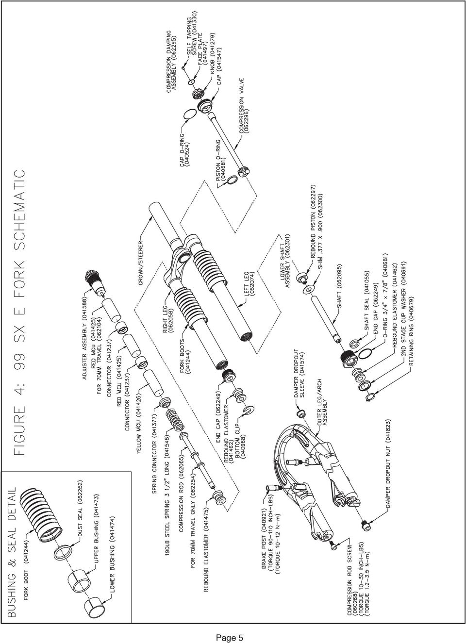
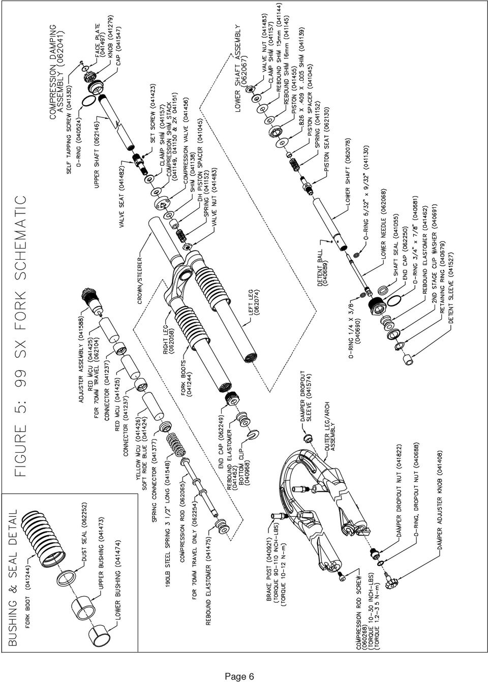
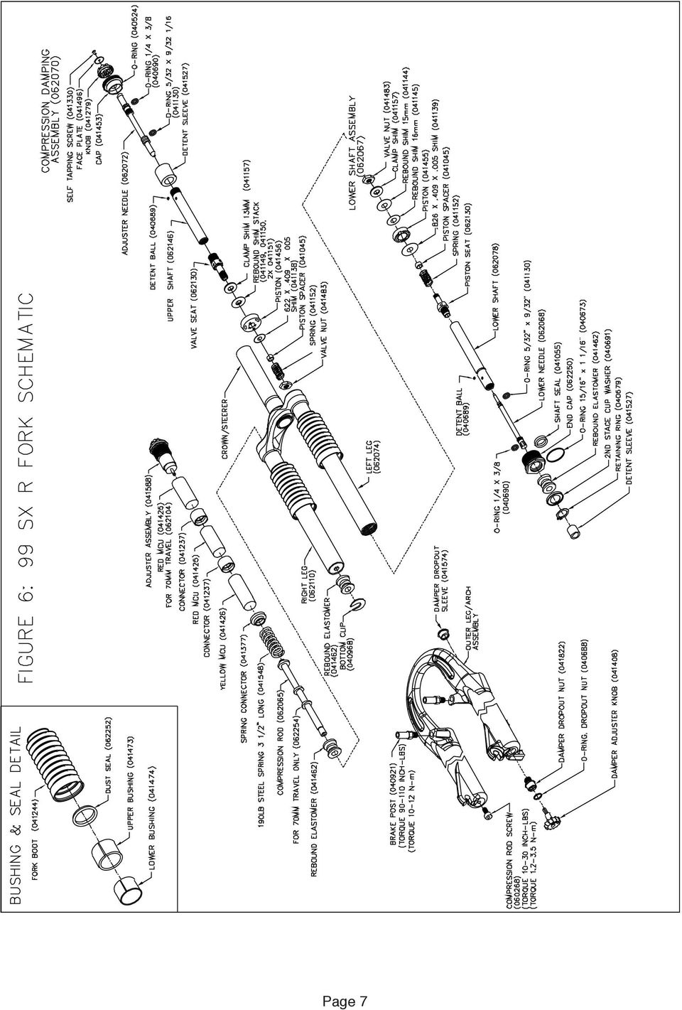
4 SPARE PARTS: Table 1 Spare parts can be ordered through your local dealer. If you have any problems that you cannot resolve with your dealer, you may call Answer Products Technical / Warranty Service Department at (805) , 8:00 AM to 5:00 PM, Pacific Standard, Monday through Friday. In addition helpful information can be found on the Answer Products Web Site, Include on the site is down loadable manuals and to technical support. DESCRIPTION PART NUMBER 99 SX TI MRD KIT LOC-OUT ASSEMBLY KIT, 80MM SOFT RIDE KIT SX E, SX, SX R, X-VERT E MEDIUM RIDE KIT SX E, SX, SX R, X-VERT E FIRM RIDE KIT SX E, SX, SX R, X-VERT E ADJUSTER KIT SPYDER R, SX, X-VERT E SX C BUSHING SEAL KIT LOC-OUT ASSEMBLY KIT, 70MM SX CROWN, 1X5.5 CM SX CROWN, 1X6.5 CM SX CROWN, 1X7.5 CM SX CROWN, 1X5.5 CM SX CROWN, 1X8.5 CM SX CROWN, 1X10.5 CM SX CROWN, 1X12.5 CM SX CROWN, 1 1/8"X5.5 CM SX CROWN, 1 1/8"X6.5 CM SX CROWN, 1 1/8"X7.5 CM SX CROWN, 1 1/8"X8.5 CM SX CROWN, 1 1/8"X10.5 CM SX CROWN, 1 1/8"X12 THRDLS CM SX CROWN, 1 1/8"X12 ALLOY SX BRAKE HANGER KIT SPYDER R & SX E COMPRESSION DAMPING ASSEMBLY SX COMPRESSION DAMPING ASSEMBLY SX, SX R & SX TI LOWER SHAFT ASSEMBLY SX, SX R & SX TI COPMRESSION DAMPING ASSEMBLY SX E LOWER SHAFT ASSEMBLY SX C LOWER SHAFT ASSEMBLY MANITOU PREP M GREASE, 6 OZ MICRO LUBE GREASE GUN HEAD MRD SUSPENSION FULID, 5WT., 8OZ MAXIMA 7.5WT SUSPENSION FLUID, 8 OZ MAXIMA 10WT SUSPENSION FLUID, 8OZ SX BUSHING SEAL KIT /99 SX TI SOFT RIDE KIT /99 SX TI MEDIUM RIDE KIT /99 SX TI FIRM RIDE KIT /99 BUSHING REMOVAL TOOL /99 BUSHING SIZING TOOL, SPYDER & SX SX OUTER ASSEMBLY BRIGHT YELLOW WITH OUT STICKERS SX OUTER ASSEMBLY BLACK WITH OUT STICKERS SX OUTER ASSEMBLY DARK BLUE WITH OUT STICKERS SX OUTER ASSEMBLY MANGO WITH OUT STICKERS SX OUTER ASSEMBLY BRIGHT RED WITH OUT STICKERS MICRO-LUBE DEMO KIT SX OUTER ASSEMBLY JADE WITH OUT STICKERS SX C OUTER ASSEMBLY BRIGHT RED WITH OUT STICKERS SX E YELLOW STICKER KIT SX E BLACK STICKER KIT Page 3

5 SPARE PARTS: Table 1 Continued DESCRIPTION PART NUMBER 99 SX DARK BLUE STICKERT KIT SX BRIGHT RED STICKER KIT SX R MANGO STICKER KIT SX R BLACK STICKER KIT SX TI YELLOW STICKER KIT SX TI DARK BLUE STICKER KIT SX C BRIGHT RED STICKER KIT SX E BRIGHT RED STICKER KIT SX YELLOW STICKER KIT SX TI JADE STICKER SX E CROWN/STEERER/LEG KIT SX CROWN/STEERER/LEG KIT SX R & SX TI CROWN/STEERER/LEG KIT SX C CROWN/STEERER/LEG KIT Page 4

6 Page 5
7 Page 6
8 Page 7
9 Page 8

10 Page 9

11 MAINTENANCE IMPORTANT: The 99 SX should not be used if any parts appear to be or are damaged. Contact your local dealer or Answer Products for replacement parts. IMPORTANT: Use of fork boots is required to keep your 99 SX performing well and your warranty in effect. Use of this fork with the boots removed will shorten the life of the fork, reduce the performance and void the warranty. Your 99 SX Fork requires periodic maintenance, cleaning, and inspection. Moisture and contamination may build up inside the fork depending on the severity of riding conditions. To maintain top performance it is recommended that the fork be periodically disassembled, cleaned, dried and re-greased. IMPORTANT: When filling the fork with grease through the grease ports it is important to note the grease is being forced between the upper and lower bushing. If the area is overfilled the force of the grease may force the upper bushing and dust seal out. IMPORTANT: Before every ride you should: 1. Ensure that quick release skewers are properly adjusted and tight. 2. Whipe the inner legs clean, lubricate and check entire fork for any obvious damage. 3. Check headset adjustment. 4. Insure that the front brake cable is properly seated in the cable retainer & check brake adjustment. FIGURE 9: LUBRICATING THE BUSHINGS IMPORTANT: Maintaining the proper oil level in your TPC is very important. Not enough oil will allow foaming and reduce the performance. Too much oil will restrict travel and may cause damage to the system and an unsafe riding situation. Finish reading this entire section prior to making any changes to the oil level. To check the oil level remove only the compression damping assembly located in the top of the left leg. Leave the right side compression stack (adjuster, MCU, spring assembly) in place to keep the fork fully extended. Use a tape measure or "dip stick" to determine the oil level. Oil level should be between 3.25" (83MM) and 4.5" (114MM) below the crown where the damping assembly screws in. The recommended level is 4.0" (102MM). It is recommended that you replace your oil at least once during the season, twice if it has been contaminated with dirt, mud, or other foreign substance. Use SAE 5WT Maxima fork oil or equivalent. See Figure 10. GENERAL DISASSEMBLY FIGURE 10: TPC OIL LEVEL NOTE: The Fork does not need to be removed from the bicycle for general disassembly-assembly or cleaning. It is also not necessary to disassemble the 98 Manitou Forks for compression Elastomer replacement. Elastomer replacement is accomplished by removing the adjuster assembly per Figure 12. Removal of outer leg / arch assembly Figure 11: 1. Use a 4MM allen wrench to remove the M6 lower compression rod screw from the right leg dropout. Pop out the damping adjuster knob from the left dropout, SXR & SX TI. A small screwdriver may be helpful. Use a 8MM allen wrench to remove the dropout nut. Fully compress the fork to prevent the compression rod and damper shaft from turning while removing screws. 2. Pull outer leg assembly down to remove from the inner legs and crown. 3. Remove fork boots. Page 10 FIGURE 12: COMPRESSION STACK

12 4. Bushing replacement will require the use of the bushing removal and installation tool available from Answer Products. It is recommended that the bushings be left installed unless they absolutely need replacement. Note: It is not recommended to remove the dust seal every time the fork is disassembled. The seal and bushings may be cleaned and re-greased in place. Compression Stack & Compression Rod Removal Figure 12: 1. Press the bottom clip off the compression rod. 2. Slide off the rebound elastomer from right leg compression rod. 3. Unscrew and remove the adjuster assembly by hand. 4. Turn fork upside down to remove the compression rod. If forks are installed on bicycle give the rod a quick upward thrust and catch it as it pops up above the crown. Lower Shaft Disassembly Figure 13: FIGURE 12: COMPRESSION STACK Note: Lower Shaft disassembly is best done with the fork removed from the bicycle. Disassembly of the damping stack is not required unless you want to change or replace the shim stack. 1. Remove the left cap compression damping assembly from the top of the fork leg and pour the oil out of the top of the fork and discard appropriately. For complete disassembly continue. 2. Remove the plastic end cap and pull the lower shaft out of the inner leg. 3. Remove the clear plastic detent sleeve and capture the 1/8" dia. Detent ball used on SX, SX R, SX TI and SX C. 4. SX, SX R, SX TI and SX C adjuster needle may be unscrewded from the shaft. 5. For SX, SX R, SX TI, and SX C use 5MM allen wrench to remove piston seat. Keep note of the exact order of the shims and spacers. FIGURE 13: LOWER TPC SHAFT ASSEMBLY Page 11

13 Compression Damping Disassembly Figure 14: 1. The compression damping assembly is almost identical to the lower shaft assembly. 2. Unscrew the compression damping adjuster all the way until it stops. The knob and the needle do not need to be removed. The shaft also does not need to be removed from the cap. The threads are bonded to prevent leaking. 3. Remove either the valve nut or the piston seat following the instructions above for the lower shaft assembly. FIGURE 14: TPC COMPRESSION DAMPING ASSEMLBY DAMPER INSPECTION 1. Check the shaft for scratches, wear, or other obvious damage. 2. Check the seal gland and end cap seal grooves for damage. 4. Check shims for permanent bends or damage. 5. Check all other parts for obvious damage, replace if necessary. 6. Replace all seals that have been removed. FORK INSPECTION 1. Check the fork boots for obvious damage. 2. Check the dust seal for tears, wear, or damage. Replace if needed. 3. Inspect the lower and upper bushing for damage to the Teflon coating. Replace using the bushing removal and replacement kits if necessary. 4. Check all MCU & springs for obvious damage. Replace if necessary. 5. Check the preload adjuster and connectors. Replace if damaged. 6. Check the outer leg/arch assembly for nicks or deep gouges on outside and inside. Replace if damaged. 7. Check the inner leg for deep gouges and other damage. Minor wear resulting in color change is not detrimental to the gold anodized surface. Replace if wear is excessive or damaged. 8. Check inner legs at the bottom of the crown for cracks or for flaking anodize. Replace crown steer leg assembly if cracked or if gold anodize is beginning to flake. 9. Check the underside of the crown for cracks. Replace if cracked. RE-ASSEMBLE Lower Shaft Figure 15: 1. Install all o-rings and seals removed. 2. Grease all seals lightly with seal grease. 3. Apply small amount of blue Locktite to piston seat threads. 4. Assemble shim stack and spacers in exact order that they were removed. For SX E, thread on valve nut and torque 30 IN-LB (3.5N-m) max. For SX, SX R SX TI, and SX C, hand tighten piston seat. Be sure large blow off washer will slide over piston spacer and compress the small spring. Clamp shaft in soft jaws or collet and line up slots in clamp ring with hole in piston seat using 1/8" or smaller pin. Use a 5MM Allen wrench and tighten piston seat by turning Allen wrench and pin at same time. Torque 30 IN-LB (3.5 N-m) max. Page12

14 5. SX, SX R, SX TI and SX C install lower needle gently into shaft, thread until it stops then back off one turn for initial adjustment. 6. Slide shaft assembly through the plastic end cap, place detent ball in place and slide on 2nd STG Elastomer. 7. Insert into left leg and thread in end cap. Torque 30 IN-LB (3.5N-m) max. 8. Add approximately 100 CC of 5 WT Maxima or equivalent oil. Do not over fill. Check oil level, see Figure 8. Compression Damping Assembly Figure 16: 1. Reassemble compression damping stack following the instructions above for the lower shaft assembly. 2. Install compression damping assembly into the left leg. The oil level should cover the compression valve when the assembly is installed. Compression Rod & Boots Figure 15: 1. Clean all parts thoroughly. 2. Grease compression rod lightly. Be sure rebound Elastomer is installed onto compression rod. 3. Drop compression rod down into inner legs. Shake inner leg to get rod through inner leg plug. 4. Slide on black second stage, cup washer, and orange 3rd stage Elastomer. 5. Slide Boots onto inner leg. FIGURE 15: COMPRESSION ROD & BOOT Outer Leg Assembly Figure 16: 1. Slide Outer leg / Arch assembly onto inner legs and fully compress. 2. Install and torque 5MM compression rod screw and dropout nut to inch-lb. ( N-m). Over torquing the dropout nut may damage the damper shaft. 3. Pop in damper adjuster knob. O-ring holds knob in place (SX, SX R, SX TI, & SX C). 4. Slide skirt of fork boots onto the outer leg groove. Be sure the lip snaps into the groove. 5. Clean adjuster cap threads thoroughly. Clean threads on inside FIGURE 16: OUTER LEG ASSEMBLY of inner leg. 6. Assemble MCU s, springs, and connectors with thick grease. 7. Install adjuster assembly into inner leg just hand tight. INNER FORK LEGS & CROWN The inner fork legs and steer tube are press fit into the crown and may never be removed. Removing them will make the fork unsafe to use. If you see any slippage contact Answer Technical Staff immediately (800) BRAKE ARCH NOTE: The 99 SX brake arch is permanently bonded to the outer legs and is not removable. If the unit is damaged or if the bond is broken or separated it must be replaced. Using the fork with a damaged brake arch bond is unsafe and could cause serious injury. Contact Answer Products if you suspect that your brake arch bond is damaged. Page13

15 ADJUSTING RIDE QUALITIES 98 SX TPC forks offer a wide adjustment range to suit individual riding preference and rider weight by simply changing the MicroCellular Urethane (MCU s). Fine tune adjustments can be made using the preload adjusters located on top of the fork crown. Softer blue and harder yellow MCU s are available from your Dealer. NOTE: Since 98 model forks use a compression stack in the right leg only, MCU s and Springs used in previous Manitou forks are NOT interchangeable with later versions of SX model Forks. Compression Spring Fine Tuning: Figure 17 Fine tuning adjustments to the spring rate are made by rotating The adjuster knobs located on top of the crown. Note the 99 SX E, SX, SX R, SX TI and SX C uses compression spring systems in both right and left legs. Both right and left knobs on top of the crown adjust preload. The right knob for those models is used to adjust preload. Rotating the knobs clockwise will firm the ride, adding preload to the compression stack. Rotating the knobs counter clockwise will soften the ride. Four full revolutions will take the adjuster from full soft to the extreme firm setting. Compression Damping Fine Tuning: Figure 18 To adjust the SX R, SX TI and SX C simply rotate the compression damping knob located on top of the left leg and crown. Rotating the knob clockwise will increase the damping, rotating the knob counter clockwise will reduce the damping. Excessive damping will give you a harsh ride over sharp bumps like rocky sections, but will feel good in large hits like G-outs. Insufficient compression damping will bottom out in the large hit G-outs and bob a little while climbing but feel plush on the sharp hits. A correctly adjusted fork will perform good in all conditions. To adjust the compression dampling for the SX remove the compression damping assembly from the top of the left leg. Adjust the set screw on the valve seat in to increase compression damping and out to reduce the compression damping. Try adjusting one half full turn at a time. The SX E uses TPC Sport for compression damping and is not adjustable. FIGURE 17: PRELOAD FIGURE 18: COMPRESSION DAMPING Rebound Damping Fine Tuning: Figure 19 To adjust the SX, SX R, SX TI and SX C simply rotate the rebound damping knob located on bottom of the left leg. Rotating the knob clockwise will increase the damping, rotating the knob counter clockwise will reduce the damping. Excessive rebound damping will give you a harsh ride over repetitive bumps (like braking bumps) because the fork will pack up. Insufficient rebound damping will make the fork over active, top out and slap back when landing from a jump. We suggest that you try adjusting your fork on the very active side, minimum rebound. Then try it over a variety of terrain and tune in more rebound from there. The SX E uses TPC Sport for Rebound damping and is not adjustable FIGURE 19: REBOUND DAMPING To adjust the rebound damping for the SX only, the left leg must be disassembled as follows: 1.) Turn the entire fork upside down. This will eliminate the need to drain the oil. 2.) Remove the dropout nut located at the bottom of the left leg and the M5 socket screw located at the bottom of the right leg. Pull the outer leg casting off of the inner legs. 3.) Stroke the damper shaft several times to transfer the oil into the upper chamber. Give the oil several minutes to drain off of the lower shaft assembly. 4.) Unscrew the damper end cap and pull out the lower shaft assembly. 5.) Adjust the set screw on the valve seat in to increase rebound damping and out to reduce the rebound damping. Try adjusting one half full turn at a time. 6.) Re-assemble. Stroke the leg several times to bleed the air out before checking the oil level. For additional tuning tips we recommend that you obtain a copy of the MRD tuning Manual P/N and check out the MRD Race Tuning kits available at your dealer. Page 14

16 TROUBLE SHOOTING Fork seems to "top out" or has a slight clunking feel when front wheel comes off the ground: Excessive preload or insufficient rebound damping will result in a "top out". Select MCU s that better fit your weight and riding style, having the preload adjuster set mid to low range, and increase the rebound damping to eliminate "top out". The fork feels less active and is not getting the travel it used to when it was new: Chances are that the fork is developing stiction. Cleaning and applying light oil to the stanchions will help. Outer legs feel loose on inner legs and bushings, a knock or rock can be felt when pushed from side to side: A very small knock is normal with the new 99 harder bushings. If the knock is excessive or you can feel the fork rocking then the bushings should be removed and replaced. To do this you must have the Answer Products Bushing Removal and Replacement Tool Kit. A small amount of oil seems to be leaking from top of the left leg at the adjuster cap: If the 99 SX us store upside down for a period of time a small amount of oil may leak through the adjuster cap / knob assembly. The cap area is not subjected to damping pressure. A small leak in that area will not affect the performance of the fork or cause any type of damage. We recommend that you store your Manitou right side up. If this condition causes you some problems please contact your Answer Products dealer or call our warranty tech department for prompt service. CYCLE COMPUTER INSTALLATION INSTRUCTIONS: Follow the instructions in your owners manual with the following exceptions: WARNING: DO NOT DRILL A HOLE IN THE DROPOUT. THIS MAY WEAKEN THE DROPOUT, WILL VOID THE WARRANTY, AND MAY CAUSE AN UNSAFE CONDITION WITH RISK OF INJURY. DO NOT USE THE TEMPLATE PROVIDED IN THE 95 OR 96 SERVICE MANUAL. Page 15

.1..2. .3..4. .5..6. .7..8.
 .1..2..3..4..5..6..7..8. .9..10..11..12..13..14..15..16..17. MANITOU SUSPENSION FORKS CONGRATULATIONS ON CHOOSING A 2003 MANITOU AXEL FORK. This Manitou AXEL fork is fully assembled and ready to be installed
2004 SERVICE MANUAL Axel Super Axel Elite Axel Comp
 2004 SERVICE MANUAL Axel Super Axel Elite Axel Comp 28209 Avenue Stanford, Valencia, California 91355 661 257-4411 fax 661 294-4179 www.answerproducts.com Table of Contents Description Page Introduction
2006 JUDY SERVICE GUIDE
 2006 JUDY SERVICE GUIDE For exploded diagram and part number information, refer to the Spare Parts Catalog available on our website at www.rockshox.com. Information contained in this publication is subject
For exploded diagram and part number information, refer to the Spare Parts Catalog available on our website at www.rockshox.com.
 For exploded diagram and part number information, refer to the Spare Parts Catalog available on our website at www.rockshox.com. Information contained in this publication is subject to change at anytime
For exploded diagram and part number information, refer to the Spare Parts Catalog available on our website at www.rockshox.com.
 For exploded diagram and part number information, refer to the Spare Parts Catalog available on our website at www.rockshox.com. 2 0 0 5 D U K E A I R X C / S L / R A C E S E R V I C E G U I D E Information
2004 SERVICE MANUAL Skareb Platinum Skareb Super Skareb Elite Skareb Comp
 2004 SERVICE MANUAL Skareb Platinum Skareb Super Skareb Elite Skareb Comp 28209 Avenue Stanford, Valencia, California 91355 661 257-4411 fax 661 294-4179 www.answerproducts.com Table of Contents Description
2006 HEADSHOK Service Video #1
 LEFTY SPEED DLR DAMPING CARTRIDGE This document explains how to properly remove, disassemble, inspect, reassemble and reinstall the Lefty Speed DLR2 damping cartridge. It is a document to be used in conjunction
MANITOU SWINGER REAR SHOCK OWNER S MANUAL P/N 042105
 MANITOU SWINGER REAR SHOCK OWNER S MANUAL P/N 042105 MANITOU SWINGER REAR SHOCK This Manitou Swinger SPV (Stable Platform Valve) shock is fully assembled and ready to be installed onto your bicycle. Special
Owner s Manual Read and keep this manual. Patents World Wide
 Owner s Manual Read and keep this manual. Patents World Wide S & S Industries, Inc., Sarasota, FL, USA www.trail-gator.com Copyright 2008 All Rights Reserved The following manual is provided to assist
VT SERIES. Owners Manual VARIABLE TRAVEL MOUNTAIN BIKE
 VT SERIES Owners Manual VARIABLE TRAVEL MOUNTAIN BIKE Multi purpose, Enduro, Trail ride, Light Freeride mountain bike Single pivot, linkage operated rear shock rear suspension Manitou Swinger SPV Air rear
INSTRUCTIONS. FLHR/C/S (Road King) FRONT END LOWERING KIT 1WARNING -J03242 REV. 10-19-04. General. Removal (Left and Right Forks) Kit Number 54614-05
 FRONT END LOWERING KIT 1WARNING -J03242 REV. 10-19-04. General. Removal (Left and Right Forks) Kit Number 54614-05") INSTRUCTIONS -J04 REV. 0-9-04 General FLHR/C/S (Road King) FRONT END LOWERING KIT This kit is designed for installation on 00 and later FLHR/C/S Model Motorcycles. Road King models use the conventional
INSTRUCTIONS -J04 REV. 0-9-04 General FLHR/C/S (Road King) FRONT END LOWERING KIT This kit is designed for installation on 00 and later FLHR/C/S Model Motorcycles. Road King models use the conventional
STEERING SYSTEM - POWER
 STEERING SYSTEM - POWER 1990 Nissan 240SX 1990 STEERING Nissan - Power Rack & Pinion Axxess, Maxima, Pulsar NX, Sentra, Stanza, 240SX, 300ZX DESCRIPTION The power steering system consists of a rack and
2003-2004 PILOT SL & XC SERVICE GUIDE
 For exploded diagram and part number information, refer to the Spare Parts Catalog available on our website at www.rockshox.com. 2003-2004 PILOT SL & XC SERVICE GUIDE Contact your local distributor or
2005-2006 PIKE REBA REVELATION DUAL AIR SERVICE GUIDE
 For exploded diagram and part number information, refer to the Spare Parts Catalog available on our website at www.rockshox.com. Information contained in this publication is subject to change at anytime
XC28 XC30. Service Manual. GEN.0000000004936 Rev A 2015 SRAM, LLC
 XC28 XC30 Service Manual GEN.0000000004936 Rev A 2015 SRAM, LLC SRAM LLC WARRANTY EXTENT OF LIMITED WARRANTY Except as otherwise set forth herein, SRAM warrants its products to be free from defects in
PALLET JACK - 2.5 TON
 PALLET JACK - 2.5 TON 39939 SET UP AND OPERATING INSTRUCTIONS Visit our website at: http://www.harborfreight.com Read this material before using this product. Failure to do so can result in serious injury.
Cane Creek Double Barrel Instructions
 Cane Creek Double Barrel Instructions Congratulations on your purchase of the Cane Creek Double Barrel (CCDB) rear shock. Developed in partnership with Öhlins Racing, the Double Barrel brings revolutionary
Ceriani Replica GP35R forks. Technical description
 Ceriani Replica GP35R forks Technical description This is an advanced racing replica of the GP35 forks. The legs are made from 6061 aluminium, mounted with CNC machined fittings, the stanchions are from
Instructions and precautions. Fork Height. Visit our website at: http://www.harborfreight.com
 Pallet Jack Item 68760 / 68761 Instructions and precautions Specifications Capacity Control Lever Fork Height Fork Length Fork Width Maximum Minimum Width over Forks Steering Wheel Dia. 2-1/2 Ton (5,000
Char-Lynn Hydraulic Motor. Repair Information. 10 000 Series. October, 1997
 Char-Lynn Hydraulic Motor October, 1997 Repair Information Geroler Motor Two Speed 001 27 Retainer inside bore of valve plate bearingless motors only 4 15 16 3 6 35 Parts Drawing 25 2 2 1 19 17 36 40 47
2003-2004 SID SERVICE GUIDE
 2003-2004 SID SERVICE GUIDE For exploded diagram and part number information, refer to the Spare Parts Catalog available on our website at www.rockshox.com. Contact your local distributor or visit the
2014 Sektor/Recon/XC32 Solo Air Service Manual
 2014 Sektor/Recon/XC32 Solo Air Service Manual SRAM LLC WARRANTY EXTENT OF LIMITED WARRANTY Except as otherwise set forth herein, SRAM warrants its products to be free from defects in materials or workmanship
CONGRATULATIONS! TABLE OF CONTENTS. 1 Safety Warnings 2 About Your Wheels 3 Setting Up Your Wheels 7 Care and Cleaning 8 Warranty
 WHEEL MANUAL CONGRATULATIONS! Congratulations on your purchase of Oval Concepts Wheels. Developed to perform at a high level, it is important that you follow the operation and maintenance instructions
Unit: mm(in) Item Standard value Service limit Axle shaft run out - 0.2(0.008)
 Item Standard value Service limit Axle shaft run out - 0.2(0.008)") Rear Wheel/Brake/Suspension 13. Rear Wheel/Brake/Suspension Service Information 13-1 Troubleshooting 13-2 Rear Wheel 13-3 Rear Cushion 13-4 Rear Swing Arm 13-7 Service Information General Safety If the
Rear Wheel/Brake/Suspension 13. Rear Wheel/Brake/Suspension Service Information 13-1 Troubleshooting 13-2 Rear Wheel 13-3 Rear Cushion 13-4 Rear Swing Arm 13-7 Service Information General Safety If the
Service Manual Rol-Lift
 R 2000 Service Manual Rol-Lift Series: T and E Developed by Generic Parts Service This manual is intended for basic service and maintenance of the Rol-Lift pallet jack. The pallet jacks you are servicing
2013 Sektor/Recon/XC32 Solo Air Service Manual
 2013 Sektor/Recon/XC32 Solo Air Service Manual GEN.0000000004207 Rev A Copyright 2012 SRAM, LLC SRAM LLC WARRANTY Extent of Limited Warranty Except as otherwise set forth herein, SRAM warrants its products
Rebuild Instructions for 70001 and 70010 Transmission
 Rebuild Instructions for 70001 and 70010 Transmission Brinn, Incorporated 1615 Tech Drive Bay City, MI 48706 Telephone 989.686.8920 Fax 989.686.6520 www.brinninc.com Notice Read all instructions before
Hydraulic Disc Brake, Installation, Maintenance, and Service Manual
 Hydraulic Disc Brake, Installation, Maintenance, and Service Manual HFX-Mag HFX-9 45-14550DWeb 02/06 copyright 2006 Hayes Bicycle Group, LLC Introduction to this Manual This manual is intended to provide
DUAL CROWN. 2011 Technical Manual
 DUAL CROWN 2011 Technical Manual TABLE OF CONTENTS GETTING STARTED...3 PARTS...3 TOOLS...3 RECORD YOUR SETTINGS...4 OIL VOLUME CHART...5 TORQUE CHART...5 SERVICE INTERVALS...5 ANATOMY...6 FORK REMOVAL...8
Table of Contents. Overview 1. Pump Disassembly 2. Control Disassembly / Reassembly 7. Pump Reassembly 13. Adjustment Procedures DR Control 19
 Table of Contents Overview 1 Pump Disassembly 2 Control Disassembly / Reassembly 7 Pump Reassembly 13 Adjustment Procedures DR Control 19 Adjustment Procedures DRG Control 20 Adjustment Procedures DFR
2003-2004 SID REAR SERVICE GUIDE
 2003-2004 SID REAR SERVICE GUIDE For exploded diagram and part number information, refer to the Spare Parts Catalog available on our website at www.rockshox.com. Contact your local distributor or visit
TABLE OF CONTENTS. Section 1 - Assembling your new pit bike.
 Orion Pit Bike Sales Owners Manual (All information and content is the property of Orion Pit Bike Sales. Any attempt to copy or resell is a direct violation of our copyright. All violators will be prosecuted)
BOXXER RC. Service Manual
 2015 BOXXER RC Service Manual SRAM LLC WARRANTY EXTENT OF LIMITED WARRANTY Except as otherwise set forth herein, SRAM warrants its products to be free from defects in materials or workmanship for a period
ASSEMBLY DIAGRAM AND ASSEMBLY REFERENCE ULTIMA OLD SCHOOL 2 EVO & TC BELT DRIVE UNITS
 ASSEMBLY DIAGRAM AND ASSEMBLY REFERENCE ULTIMA OLD SCHOOL 2 EVO & TC BELT DRIVE UNITS BELT DRIVE ASSEMBLIES Part# 58-850 2 Old School Belt Drive Assembly - Polished Part# 58-851 2 Old School Belt Drive
Round Housing with Side Ports
 Power Steering Steering Control Unit (SCU) Parts and Repair Information 5 Series Steering Control Units 001 Square Housing with Side Ports Round Housing with Side Ports T E L RP Round Housing with End
FJ2. 2 Ton Trolley Floor Jack Assembly & Operating Instructions
 FJ2 2 Ton Trolley Floor Jack Assembly & Operating Instructions READ ALL INSTRUCTIONS AND WARNINGS BEFORE USING THIS PRODUCT. This manual provides important information on proper operation & maintenance.
Operating Instructions Parts List Manual Scissor Lift Pallet Truck
 Operating Instructions Parts List Manual Scissor Lift Pallet Truck Note: Operator MUST read and understand this operating instructions before use this Hand Scissor Lift. Thank you for using this hand scissors
Giant NRS. Model Year. Owners Manual. July 2003.
 Giant NRS Model Year 2004 Owners Manual July 2003. Contents. 1. Introduction.... 2 2. Sizing.... 3 3. Exploded view... 4 4. Rear suspension... 5 4-1 NRS rear suspension system.... 5 4-2 Bikes equipped
STEERING HANDLEBAR/FRONT WHEEL/ FRONT SHOCK ABSORBER
 14 14 STEERING HANDLEBAR/FRONT WHEEL/ SCHEMATIC DRAWING ------------------------------------------------- 14-1 SERVICE INFORMATION------------------------------------------------ 14-2 TROUBLESHOOTING-----------------------------------------------------
TUNING GUIDE. ridefox.com
 TUNING GUIDE ridefox.com OUR LIGHTEST 34 FORK EVER: REDESIGNED FOR 27.5 AND 29 WHEEL SIZES The model year 2016 34 offers many of the benefits from the 36; rigidity and improved traction for aggressive
for DS3 R3 USER HANDBOOK
 USER HANDBOOK for DS3 R3 2 3 4 6 10 11 11 12 13 15 14 6 8 Introduction Tuning your dampers Detailed views : Mc Pherson Eyelet / eyelet Technical datas Tightening torques Maintenance and inspection Specific
MP-4V Heavy Duty Riveter / 39048
 MP-4V Heavy Duty Riveter / 39048 This newly designed heavy-duty air/hydraulic riveter is ergonomically designed with the professional in mind. The light weight 3.7 lbs. well balanced MP-4V includes a Vacuum
Joplin Rebuild Instructions
 Joplin Rebuild Instructions This is a step by step list of instruction on how to rebuild the Crankbrothers Joplin post. It may not always be required to completely tear-down the post to do the work needed
White Industries Rear Hub Instructions
 White Industries Rear Hub Instructions Tool required: 2mm allen/hex wrench, 19mm socket, 20mm socket, and mallet. 1. Loosen the set screws located in the adjusting collar by using a 2mm allen wrench inserted
cbperformance.com Please read this entire brochure prior to installing your CB Performance Products MAGNASPARK II distributor.
 - Easy -wire installation with no external spark box necessary, but can be used with one. - Precision CNC machining and hand assembled construction. This is a premium product. - Accurate super hot spark
Dive Rite 200 & 300 Bar Isolator Manifold Service Manual
 Dive Rite 200 & 300 Bar Isolator Manifold Service Manual Principal Photography and Text by Pete Nawrocky Copyright 2003 Lamartek Inc. D/B/A Dive Rite 0 Warning This manual is only to be used as a guide
Pallet Jack. OWNER S MANUAL Model MH1230. Important Safety Instructions Assembly Instructions Parts and Hardware Identification
 OWNER S MANUAL Model MH1230 Important Safety Instructions Assembly Instructions Parts and Hardware Identification Pallet Jack CAUTION: Read, understand and follow ALL instructions before using this product
2011 Technical Manual
 2011 Technical Manual SRAM LLC WARRANTY SRAM warrants its products to be free from defects in materials or workmanship for a period of two years after original purchase. This warranty only applies to the
2007 Fork Service Manual. Rev 8/28/06
 2007 Fork Service Manual Rev 8/28/06 1 Table of ontents Description Page Introduction 3 Front Suspension Terminology 4 Section 1 - Disassembly/ssembly Instructions Damping Systems -B Kits Section 2 rown
TUTORIAL. REbUILdING. front CALIpER O-RING CONVERSION CORVETTE 1965-82. Part #: HT-1
 Part #: HT-1 1965-82 CORVETTE O-RING CONVERSION front CALIpER REbUILdING TUTORIAL Choosing a Brake Caliper Rebuild Kit Standard Lip Seals vs. O-Ring Seals Lip seal design seals are used on 1965-1982 Corvette
Drive shaft, servicing
 Volkswagen Passat B6 - Drive shaft, servicing Стр. 1 из 41 40-7 Drive shaft, servicing Drive shafts, overview I - Assembly overview: Drive axle with CV joint VL100 40-7, Drive axle with CV joint VL100,
2016 Lyrik. Service Manual. GEN.0000000005042 Rev B 2015 SRAM, LLC
 2016 Lyrik Service Manual GEN.0000000005042 Rev B 2015 SRAM, LLC SRAM LLC WARRANTY EXTENT OF LIMITED WARRANTY Except as otherwise set forth herein, SRAM warrants its products to be free from defects in
Volkswagen Jetta, Golf, GTI 1999, 2000 Brake System 46 Brakes - Mechanical Components (Page GR-46)
") 46 Brakes - Mechanical Components (Page GR-46) Front brakes Brake pads, removing and installing Brake pads, removing and installing FN 3 brake caliper, servicing FS III brake caliper, servicing Rear wheel
46 Brakes - Mechanical Components (Page GR-46) Front brakes Brake pads, removing and installing Brake pads, removing and installing FN 3 brake caliper, servicing FS III brake caliper, servicing Rear wheel
13. REAR WHEEL/BRAKE/SUSPENSION
 13. REAR WHEEL/BRAKE/SUSPENSION 13 3.5~4.5kg-m 8.0~10.0kg-m 0.8~1.2kg-m 3.0~4.0kg-m 2.4~3.0kg-m 3.5~4.5kg-m 6.0~8.0kg-m 13-0 13. REAR WHEEL/BRAKE/SUSPENSION 13 REAR WHEEL/BRAKE/SUSPENSION SERVICE INFORMATION...
Rear wheel brakes, servicing. Стр. 1 из 45. Note:
 Volkswagen Touareg - Rear wheel brakes, servicing Стр. 1 из 45 46-2 Rear wheel brakes, servicing Rear brakes, FN 44 brake caliper, servicing Note: After replacing brake pads, depress brake pedal firmly
AXLE SHAFTS - FRONT. 1998 Pontiac Bonneville MODEL IDENTIFICATION DESCRIPTION & OPERATION TROUBLE SHOOTING REMOVAL & INSTALLATION
 AXLE SHAFTS - FRONT 1998 Pontiac Bonneville 1998-99 DRIVE AXLES FWD Axle Shafts - Cars - "C", "G" & "H" Bodies GM Aurora, Bonneville, Eighty Eight, LeSabre, LSS, Park Avenue, Regency, Riviera MODEL IDENTIFICATION
ROTOR LOADER OWNER S MANUAL
 ROTOR LOADER OWNER S MANUAL ROTOR LOADER OWNER S MANUAL WARNING IMPORTANT SAFETY INSTRUCTIONS AND GUIDELINES. Misuse of paintball equipment may cause serious injury or death. QUICK SET-UP GUIDE BATTERY
2011 Technical Manual
 2011 Technical Manual SRAM LLC Warranty Extent of Limited Warranty SRAM warrants its products to be free from defects in materials or workmanship for a period of two years after original purchase. This
2011 - PRESENT DOMAIN DUAL CROWN. Service Manual
 2011 - PRESENT DOMAIN DUAL CROWN Service Manual SRAM LLC WARRANTY EXTENT OF LIMITED WARRANTY Except as otherwise set forth herein, SRAM warrants its products to be free from defects in materials or workmanship
SCION tc 2005-2008 COIL OVER SUSPENSION Preparation
 SCION tc 2005-2008 COIL OVER SUSPENSION Preparation Part Number: PTR11-21070 NOTE: Part number of this accessory may not be the same as the part number shown. Kit Contents: Item # Quantity Reqd. Description
INSTRUCTIONS AND PARTS LIST FOR MODEL 70H & 75H HAND-OPERATED HYDRAULIC PRESS
 INSTRUCTIONS AND PARTS LIST FOR MODEL 70H & 75H HAND-OPERATED HYDRAULIC PRESS SETTING UP THE PRESS FOR OPERATION For shipping convenience, the gauge, pump handle, hoist crank, screw nose and base angles
DYNA RIDER FOOTBOARD KIT
 -J0 REV. 0-0-0 DYNA RIDER FOOTBOARD KIT GENERAL Kit Number 000 Models For model fitment information, see the P&A Retail Catalog or the Parts and Accessories section of www.harley-davidson.com (English
HYDRAULIC LIFT TABLE CART 2200-LB.
 HYDRAULIC LIFT TABLE CART 2200-LB. OWNER S MANUAL WARNING: Read carefully and understand all MACHINE ADJUSTMENT AND OPERATION INSTRUCTIONS before operating. Failure to follow the safety rules and other
Parts#MB003-003 Reverse Gear MAMBA (Monoblock for Cable operated) For 5 speed Trans., '87 to '06 Big Twin models (except '06 Dyna)
 For 5 speed Trans., '87 to '06 Big Twin models (except '06 Dyna)") Installation Instructions Reverse Gear MAMBA (Monoblock for Cable operated) Read and become familiar with these installation instructions before start. Two Piece for H-D 5 Speed Trans., Cable operated
Installation Instructions Reverse Gear MAMBA (Monoblock for Cable operated) Read and become familiar with these installation instructions before start. Two Piece for H-D 5 Speed Trans., Cable operated
TUTORIAL. REbUILdING. REAR CALIpER O-RING CONVERSION CORVETTE 1965-82. Part #: HT-2
 Part #: HT-2 1965-82 CORVETTE O-RING CONVERSION REAR CALIpER REbUILdING TUTORIAL Choosing a Brake Caliper Rebuild Kit Standard Lip Seals vs. O-Ring Seals Lip seal design seals are used on 1965-1982 Corvette
Triple Threat 3-in-1 Game Table 3 IN 1 GAME TABLE
 NG0M Triple Threat 3-in- Game Table 3 IN GAME TABLE Thank 3 in Y Game Table Thank you for your purchase of our product. We work around the clock and around the globe to ensure that our products maintain
This is the civilian transfer case with the cooling loop only found in the driven gear half of the front case.
 INTRODUCTION The Transfer case used in the AMG Hummer is a New Venture Gear, model 242. This case has been in use for the H-1/Hummer since the early 1990 s. There have been modifications to the internal
Overview PARTS LIST. B. Lever mounting base C. Flush handle assembly D. Grey/Blue float stop E. Grey float (Full Flush) F. Flush valve washer
 F. Flush valve washer") Overview READ ENTIRE INSTRUCTIONS BEFORE STARTING INSTALLATION PARTS LIST A. Flush valve B. Lever mounting base C. Flush handle assembly D. Grey/Blue float stop E. Grey float (Full Flush) F. Flush valve
Overview READ ENTIRE INSTRUCTIONS BEFORE STARTING INSTALLATION PARTS LIST A. Flush valve B. Lever mounting base C. Flush handle assembly D. Grey/Blue float stop E. Grey float (Full Flush) F. Flush valve
Your New Frog Bike. Congratulations on purchasing a new bike and thank you for choosing Frog!
 Your New Frog Bike Congratulations on purchasing a new bike and thank you for choosing Frog! We know that you must be raring to go but before you do there s a few little things still to do to get you up
Front brakes (FN- 3), servicing
, servicing") j a t Front brakes (FN- 3), servicing 46-1 Front brakes, servicing Note: Install complete repair kit. After replacing brake pads and before moving vehicle, depress brake pedal several times firmly to properly
j a t Front brakes (FN- 3), servicing 46-1 Front brakes, servicing Note: Install complete repair kit. After replacing brake pads and before moving vehicle, depress brake pedal several times firmly to properly
DO NOT attempt to repair hub and wheel bearing assembly.
 Page 1 of 6 HUB & WHEEL BEARINGS (WITH PULSE VACUUM HUBLOCK) DO NOT attempt to repair hub and wheel bearing assembly. Removal DO NOT remove hub lock assembly by prying on hub lock legs. This can crack
IMPORTANT DOCUMENTATION DO NOT DISCARD!
 PART NO.: 6441-263C SERIES GRT 3 JAW PARALLEL GRIPPERS INFORMATION SHEET IMPORTANT DOCUMENTATION DO NOT DISCARD! Use this information sheet to assist with gripper installation and setup. File with maintenance
Slide the new steering column shaft through the steering column from the driver compartment.
 Slide the new steering column shaft through the steering column from the driver compartment. Push the column shaft through the steering column until the machined end is out past the column lower bushing.
Repair of Hyd-ro-ac Actuators
 Repair of Hyd-ro-ac Actuators OVERHAUL INSTRUCTIONS SS-.2A-1V SS-.5A-1V SS-.5A-2V Read the entire contents of these instructions before installing the actuator and before making any connections to the
HYDRAULIC TABLE CART
 Owner s Manual & Safety Instructions Save This Manual Keep this manual for the safety warnings and precautions, assembly, operating, inspection, maintenance and cleaning procedures. Write the product s
Fleck 4650. Service Manual INSTALLATION AND START-UP PROCEDURE TABLE OF CONTENTS JOB SPECIFICATION SHEET
 Fleck 4650 Service Manual TABLE OF CONTENTS JOB SPECIFICATION SHEET...1 INSTALLATION AND START-UP PROCEDURE...1 CONTROL VALVE DRIVE ASSEMBLY...2 CONTROL DRIVE ASSEMBLY FOR CLOCK...3 BYPASS VALVE ASSEMBLY...4
CHAPTER 65 TAIL ROTOR DRIVE SYSTEM. Section Title Page
 CHAPTER 65 TAIL ROTOR DRIVE SYSTEM Section Title Page 65-00 Description........................................ 65.1 65-10 Tail Rotor Drive Fan Shaft.............................. 65.1 65-20 Tail Rotor
RS-1. Service Manual
 2015 RS-1 Service Manual SRAM LLC WARRANTY EXTENT OF LIMITED WARRANTY Except as otherwise set forth herein, SRAM warrants its products to be free from defects in materials or workmanship for a period of
Owners & Installation Manual for the Sheridan, Mountainair, Pine Valley and Old Forge Ceiling Fan Family
 Owners & Installation Manual for the Sheridan, Mountainair, Pine Valley and Old Forge Ceiling Fan Family Part of the Kiva Lighting Family Custom Lighting and Fans Since 1992 1312 12th St NW Albuquerque,
300 SERIES 331, 332, 333, 344, 356 AND 367 MODELS
 Section: MOYNO 500 PUMPS Page: 1 of 8 Date: March 1, 1998 SERVICE MANUAL MOYNO 500 PUMPS 300 SERIES 331, 332, 333, 344, 356 AND 367 MODELS Mechanical Seal Models Packing Gland Models MODELS DESIGN FEATURES
DETACHABLE WINDSHIELD AND DOCKING HARDWARE KIT
 -J00 REV. 00-- DETACHABLE WINDSHIELD AND DOCKING HARDWARE KIT GENERAL Kit Number -A, 0-, -, 0-, -, - 0, -0 Models These kits fit and later FXST, FXSTB, FXSTC, and and later FXDWG Harley-Davidson model
Installation manual. 1.75 front leveling kit. 2011 Dodge Durango 2011-2014 Jeep Grand Cherokee. Part # 42006. Part # 42006
 Installation manual 1.75 front leveling kit 2011 Dodge Durango 2011-2014 Jeep Grand Cherokee Part # 42006 sj02282011rev.01 Part # 42006 2011-2014 Dodge Durango 2011 Jeep Grand Cherokee 1.75 front leveling
Manual for GlobePharma Mini-Press II Rotary Tablet Press
 1 of 13 Preparing the Rotary Press 1. Make sure the rotary press is unplugged. 2. Open the bottom cabinet of the rotary press and take out the grey tool kit, and the beige box of punches and dies. 3. Take
MUSTANG II IFS COMPLETE PARTS PACKAGE
 MUSTANG II IFS COMPLETE PARTS PACKAGE Your Southern Rods & Parts Mustang II IFS Parts Package contains the following items: 1 pr) Upper Control Arms (2023) 1) Upper Arm Bolt Kit (MP-001-A) 1 pr) Lower
ARTICLE BEGINNING APPLICATION IDENTIFICATION DESCRIPTION LUBRICATION & ADJUSTMENT TROUBLE SHOOTING. MANUAL TRANSMISSIONS Saab 5-Speed Transaxle
 Article Text ARTICLE BEGINNING MANUAL TRANSMISSIONS Saab 5-Speed Transaxle APPLICATION TRANSMISSION APPLICATION ÄÄÄÄÄÄÄÄÄÄÄÄÄÄÄÄÄÄÄÄÄÄÄÄÄÄÄÄÄÄÄÄÄÄÄÄÄÄÄÄÄÄÄÄÄÄÄÄÄÄÄÄÄÄÄÄÄÄÄÄ Vehicle Application Transmission
MONARCH PLUS RC3/R. Service Manual
 2015 MONARCH PLUS RC3/R Service Manual SRAM LLC WARRANTY EXTENT OF LIMITED WARRANTY Except as otherwise set forth herein, SRAM warrants its products to be free from defects in materials or workmanship
Stainless Steel Single and Dual Circulation Kits
 Instruction Sheet P/N 160780 01 Stainless Steel Single and Dual Circulation Kits Introduction The single and dual high-pressure circulation kits allow you to vary and control the circulation rate of coating
SERVICE PARTS LIST PAGE 1 OF 6 BASE ASSEMBLY SPECIFY CATALOG NO. AND SERIAL NO. WHEN ORDERING PARTS 12" DUAL BEVEL COMPOUND MITER SAW B27A
 PAGE 1 OF 6 BASE ASSEMBLY 00 0 EXAMPLE: Component Parts (Small #) Are Included When Ordering The Assembly (Large #). SPECIFY CATALOG NO. AND NO. WHEN ORDERING PARTS 1 02-80-0050 Thrust Bearing (1) 2 05-80-0510
PEDAL CAR - GO CART ASSEMBLY & OPERATING INSTRUCTIONS
 PEDAL CAR - GO CART 42822 ASSEMBLY & OPERATING INSTRUCTIONS 3491 Mission Oaks Blvd., Camarillo, CA 93011 Visit our Web site at: http://www.harborfreight.com Copyright 2000 by Harbor Freight Tools. All
H EAD TUBE BASICS. Figure 1 - Head tube, front fork and hardware
 H EAD TUBE BASICS Figure 1 - Head tube, front fork and hardware This tutorial will cover some of the basics you need to know when pulling apart the steering system of a bicycle for repair or use on one
Hydraulic Transmission Jacks Operating Instructions & Parts Manual
 Blackhawk Automotive is a Licensed Trade Mark Made by SFA Companies, Kansas City, MO Hydraulic Transmission Jacks Operating Instructions & Parts Manual Model BH7011 BH7210 Capacity 1/2 Ton 1 Ton SFA Companies
Assembly and Usage Instructions
 Assembly and Usage Instructions A Product 5885 West Van Horn Tavern Road Columbia, MO 65203 www.caldwellshooting.com Instruction #1001667 Limited Warranty Every Caldwell product is warrantied to be free
HYDRAULIC TABLE CART 500-LB.
 HYDRAULIC TABLE CART 500-LB. OWNER S MANUAL WARNING: Read carefully and understand all MACHINE ADJUSTMENT AND OPERATION INSTRUCTIONS before operating. Failure to follow the safety rules and other basic
Depending on which elastic support you have you can secure the V2 power unit to the following seat bracket tubes: EXTERNAL DIAMETER 27.
 ASSEMBLY 1 - EPS V2 POWER UNIT (SOLUTION 5) 1.1 - POSITIONING INSIDE THE SEAT TUBE WITH ELASTIC SUPPORT IN THE SEAT BRACKET TUBE Depending on which elastic support you have you can secure the V2 power
Back Pack Sprayer. Operator's Manual MODELS MS - 40 MS - 50
 Back Pack Sprayer Operator's Manual MODELS MS - 40 MS - 50 WARNING DANGER Read rules for safe operation and all instructions carefully. ECHO provides this Operator's Manual which must be read and understood
SELF-STEERING AXLE TABLE OF CONTENTS
 SELF-STEERING AXLE TABLE OF CONTENTS Section 1 - Introduction Section 2 - Pre-Installation Check List Section 3 - Ride Height Adjustments Section 4 - Suspension Mount Section 5 - Axle Mount Section 6 -
2014 Monarch RT3/R Service Manual
 2014 Monarch RT3/R Service Manual SRAM LLC WARRANTY Extent of Limited Warranty Except as otherwise set forth herein, SRAM warrants its products to be free from defects in materials or workmanship for a
2013 Monarch RT3 Service Manual
 2013 Monarch RT3 Service Manual GEN.0000000004179 Rev A Copyright 2012 SRAM, LLC SRAM LLC WARRANTY Extent of Limited Warranty Except as otherwise set forth herein, SRAM warrants its products to be free
Table of Contents WARNING SYMBOLS AND DEFINITIONS
 Table of Contents SAFETY INSTALLATION OPERATION MAINTENANCE Safety... 2 Specifications... 4 Installation... 5 Operation... 8 WARNING SYMBOLS AND DEFINITIONS Maintenance... 9 Parts List and Assembly Diagram...