POWERPOLE CONNECTOR GENERAL INSTALLATION TIPS
|
|
|
- Reynold Porter
- 7 years ago
- Views:
Transcription
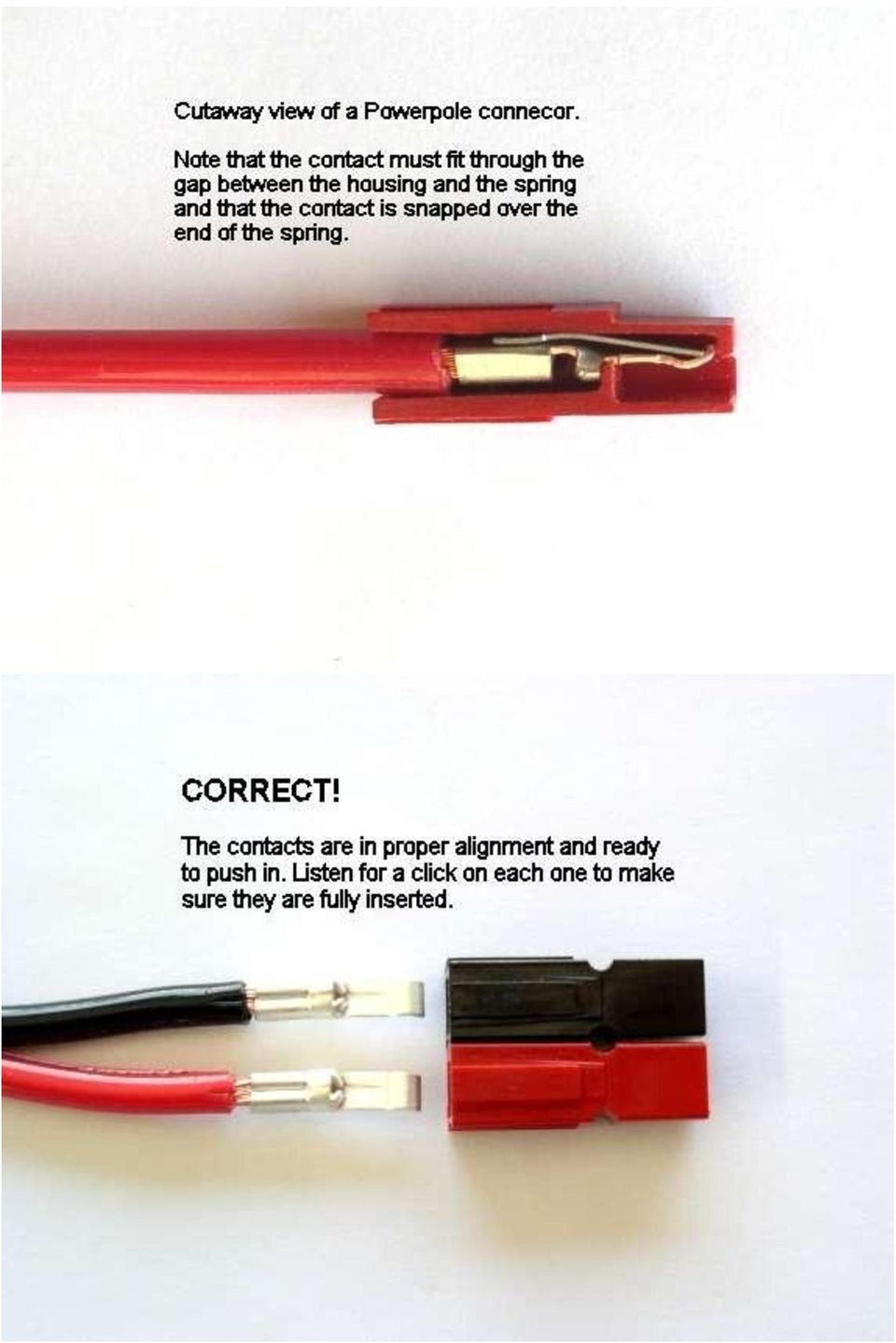
1 POWERPOLE CONNECTOR GENERAL INSTALLATION TIPS Assemble the red and black plastic housings together correctly on the first try, they fit snugly and can be difficult to get apart. See the picture below for ARES /RACES standard orientation that the RIGrunner uses. Note that you can assemble the red and black insulated housings in other ways for special applications. Put the connector housings together before putting the connector pins in, this is easier, especially when using heavy paired wire. Before soldering or crimping the contacts on to heavy paired wire, orient the contacts so that they are both facing the correct direction so that they go in the housings without twisting the wire. The plastic housings are held together with dovetail joints. Always slide these joints together! They will be damaged if you try to snap them together or apart. They ONLY slide together in one direction. This should be obvious by looking at them carefully. Do not use roll pins on Powerpoles? Some people supply roll pins with Powerpoles? Do not use them, they can and will fall out, and knowing Murphy, right in to your new radio causing smoke! Anderson does not supply or recommend roll pins, they supply not roll pins but much more expensive spiral pins, which are better. We have tested both, even the proper spiral pins will fall out. If the pair of heavy wires are squeezed together near the back of the connector, like you might do when you pull the connector out, it will spread the bodies apart slightly and out falls the pin. We spoke to Anderson about this concern and they said that they recommend using a cyanocrylic glue, Crazy Glue, hold the connector bodies permanently together. They do not recommend their spiral pins for critical applications. Normally the dovetail joints in the housings hold well. If you find it necessary, glue them, don't use pins. Make sure you have them assembled correctly BEFORE you glue, they will be permanently bonded together with a cyanocrylic. All it takes is a very small drop of cyanocrylic glue in the seam between the red and black bodies. N9EF suggests a bit of silicon glue injected in to the hole between the red and black housings. He says it holds them together quite well but they can be separated if needed.

2 The contacts go in the housings in only one way. Insert the contacts with their sharp edge down against the flat spring that is in the housing. They should slide in and click. If you do not hear a click or they are not fully seated, fix them. When they are inserted fully you should notice that the contact and it's wire "floats" slightly inside it's housing. If it feels tight it may not be snapped in fully or you have made the contact wider than it originally was during crimping or soldering. YOU WILL NOT BE ABLE TO INSERT THE CONTACTS INTO THE HOUSINGS IF THEY ARE TOO WIDE AFTER SOLDERING OR CRIMPING!

3
4

5
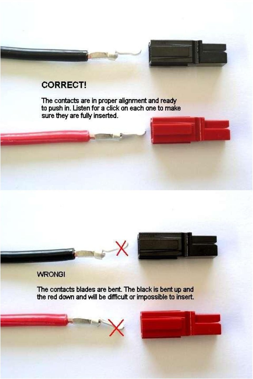
6 Tug slightly on the assembled connector to make sure the contacts are locked in place. If you have trouble getting the contact to lock in to the housing you may have squashed the contact wider deformed it some how. Look at the side profile of the contacts before and after crimping, you may have to bend it back straight before inserting it in to the housing. When soldering the contact pins, be careful not to use too much solder. Keep the solder inside, where the wire goes. If a blob of solder gets on the outside of the connector body you may have trouble putting the contact into the housing. If you get solder on the contact surface area you will not make a good contact. When crimping the contact pins use a crimp that contains the wire completely inside the pin and doesn't spread the connector apart. A good crimp is one where the dimensions of the crimped portion are no more than an un-crimped pin. If the crimp is flattened out you will not be able to easily push the pin in to the body. If you bend the contact blade in relation to the crimp area you should straighten it before putting it in to the body. It is possibly to use larger or smaller gauge wire with the 30 and 45 amp connectors. The 30 amp connector pins will work with difficulty with #10 wire if you cut the end cleanly and carefully put each and every strand of that wire in to the pin. It may be is easier to use 45 amp connectors on #10 wire. Using 16 gauge or smaller wire in a 30 amp contact requires that you double or triple up the wire to fill the crimp receptacle of the contact to get a good crimp. A properly crimped contact should have a minimum hold on the wire of more than 25 pounds. A pair of connectors should snap together with 6 to 8 pounds force. Last but not least, MAKE SURE you have the polarity correct before plugging in you equipment. "Measure twice, cut once" as the saying goes. Copyright 2012 West Mountain Radio

Anderson Powerpoles. Powerpole Assembly Instructions for SCOUT, NAVIGATOR AND RANGER ROV s
 Anderson Powerpoles Powerpole Assembly Instructions for SCOUT, NAVIGATOR AND RANGER ROV s Anderson Powerpoles Power Connections NEW in 2016!!! ELEC-010E: Power supply connections will be Red/Black Anderson
Bill Conkling July 2012
 Bill Conkling July 2012 Introduction: For any ham, there are moments that are priceless, like snagging that elusive rare DX station on a deserted island that hasn t been activated in 52 years. And certainly,
User s Manual. BNC Mini-High Res, 75 Ohm Termination Kit Connector Installation Guide (60-073-01)
") User s Manual BNC Mini-High Res, 75 Ohm Termination Kit Connector Installation Guide (60-073-01) BNC Termination Kit Instructions This document is a compilation of Extron s instructions, together with
User s Manual BNC Mini-High Res, 75 Ohm Termination Kit Connector Installation Guide (60-073-01) BNC Termination Kit Instructions This document is a compilation of Extron s instructions, together with
Time needed: ~3h for lid replacement only. Add 1h for operation harness in lid and ~2h more for installing drive unit and cable harness in trunk.
 DIY for replacing trunk lid and/or retrofitting electrical operation of trunk lid. This document is meant to be a support and give advice on the procedure but I will take no responsibility for any damage
GT3B Hack Kit Install Instructions Written By Austin Hutchison
 GT3B Hack Kit Install Instructions Written By Austin Hutchison Step 1: Remove 4 screws located on top of the radio. 1 Step 2: There are small plastic latches that also hold the top in place. The easiest
ROTOPOD PERISCOPE LIGHTING KIT (for MCWHLR & Daniel D/Xeno Periscopes)
") ROTOPOD PERISCOPE LIGHTING KIT (for MCWHLR & Daniel D/Xeno Periscopes) 14-APR-2012_rev 1.2 I designed the Periscope Lighting Kit to be as flexible as possible. Every LED is individually controllable. I
ROTOPOD PERISCOPE LIGHTING KIT (for MCWHLR & Daniel D/Xeno Periscopes) 14-APR-2012_rev 1.2 I designed the Periscope Lighting Kit to be as flexible as possible. Every LED is individually controllable. I
AMPSEAL* Automotive Plug Connector and Header Assembly
 AMPSEAL* Automotive Plug Connector and Header Assembly Application Specification 24 SEP 97 Rev E All dimensions are given in millimeters unless otherwise specified. All dimensional tolerances are +0.2
Triac Printed Circuit Board Replacement
 Technical Service Bulletin: Triac Printed Circuit Board Replacement TRONIC 5000C Pro Models: WH17, WH27, WH36 Introduction Fig. 1 ELECTRICITY IS EXTREMELY DANGEROUS. TAKE EXTRA PRECAUTIONS AND ENSURE ALL
Retrofit Instructions Installing a Sport Heated Steering Wheel - Leather, Multifunction BMW X5, E53, 2001 2006
 Retrofit Instructions Installing a Sport Heated Steering Wheel - Leather, Multifunction BMW X5, E53, 2001 2006 Disclaimer: This set of instructions is simply a guide on how I installed my own heated steering
SIG 556 Match Sear/Hammer Installation
 SIG 556 Match Sear/Hammer Installation ShootingSight LLC 2012 Safety Warning Always verify your firearm is unloaded before working on it. These instructions are meant as a supplemental guide to an armorer
LED Wiring and Connections
 LED Wiring and Connections A Handbook of How-to Manuals 2009 usledsupply. All Rights Reserved. Index These step by step how to manuals will give you the foundation necessary to use your new LED lights.
Instructions for Using the Watch Works Tool Kit to Change a Watch Battery
 Instructions for Using the Watch Works Tool Kit to Change a Watch Battery Click on this link http://www.allamericanwatches.com/site/626101/product/e2306-a to purchase the Watch Battery Replacement Tool
FREEBIRD THE ORIGINAL D.I.Y. ORNITHOPTER! Tools and Glue. Required Materials
 Do not try to make your ornithopter using "household materials". If you want it to fly, you have to build it right. FREEBIRD THE ORIGINAL D.I.Y. ORNITHOPTER! Wingspan: 16 inches Weight: 1/4 ounce The Ornithopter
Build a Junior Solar Sprint Model Car Kit Materials: 1 PITSCO Ray Catcher Sprint Kit or Solar Made Junior Solar Sprint Kit 1 White Sheet of Plastic
 Build a Junior Solar Sprint Model Car Kit Materials: 1 PITSCO Ray Catcher Sprint Kit or Solar Made Junior Solar Sprint Kit 1 White Sheet of Plastic Coated Paper 2 Balsa Sheets (10-1/2 x4 x3/16 ) 2 Alligator
Your Simple Guide to Battery. www.firstalertpro.com. Replacement. Customer Care: 1-800-852-0086. www.firstalertpro.
 Previous Menu Your Simple Guide to Battery www.firstalertpro.com Replacement p e t s ts ep -by Customer Care: 1-800-852-0086 FA/1565 9/00 www.firstalertpro.com Table of Contents: page Introduction...............................
Z-Truck (Vertical Moving) Z-truck Flag. Y-Truck (Horizontal Moving) FIGURE 1: VIEW OF THE Z-TRUCK. Flexshaft Assembly
 Z-truck Flag. Y-Truck (Horizontal Moving) FIGURE 1: VIEW OF THE Z-TRUCK. Flexshaft Assembly") Replacing the Cover Micro-Switch To remove and replace the Cover Micro-Switch you will need the following tools: #2 Phillips screwdriver (magnetic tip preferred) #1 Phillips screwdriver (magnetic tip preferred)
Replacing the Cover Micro-Switch To remove and replace the Cover Micro-Switch you will need the following tools: #2 Phillips screwdriver (magnetic tip preferred) #1 Phillips screwdriver (magnetic tip preferred)
Martin County Amateur Radio Association. Nightfire Kits 1 LED Torch Kit 270016. Contents. Description
 Nightfire Kits 1 LED Torch Kit 270016 1 Contents Nightfire Kits LED Torch Kit 270016... 1 Description... 1 Safety and Assembly of the kit... 6 Required and Useful Tools... 7 Assembly... 8 Checkout and
RS232/DB9 An RS232 to TTL Level Converter
 RS232/DB9 An RS232 to TTL Level Converter The RS232/DB9 is designed to convert TTL level signals into RS232 level signals. This cable allows you to connect a TTL level device, such as the serial port on
Building A Computer: A Beginners Guide
 Building A Computer: A Beginners Guide Mr. Marty Brandl The following was written to help an individual setup a Pentium 133 system using an ASUS P/I- P55T2P4 motherboard. The tutorial includes the installation
Gear PEPSI CAN STOVE INSTRUCTIONS
 Gear PEPSI CAN STOVE INSTRUCTIONS [NOTE: Updated Instructions are now available. The new stove is less likely to develop flame leaks and the fuel/air mixture is improved. Instructions for a simmer ring
UPGRADING AND SERVICING GUIDE
 UPGRADING AND SERVICING GUIDE HPTouchSmart 610 PC Computer features may vary by model. Removing and Replacing a CD/DVD Drive...2 Removing the CD/DVD Drive... 2 Installing a New CD/DVD Drive... 5 Removing
WIRE, TERMINAL AND CONNECTOR REPAIR CONDUCTORS
 CONDUCTORS Conductors are needed to complete the path for electrical current to flow from the power source to the working devices and back to the power source. Special wiring is needed for battery cables
Electronics and Soldering Notes
 Electronics and Soldering Notes The Tools You ll Need While there are literally one hundred tools for soldering, testing, and fixing electronic circuits, you only need a few to make robot. These tools
Assembly Instruction CAI- Connector with universal Endbell
 CANNON STANDARD Seite 1 von 17 CAI- Connector with universal Endbell Shell size 10 to 36 with APK contact / Trident T2P - contact Illustration and assembly exemplary of CAI Layout 20-0306 with APK / Trident
Andersen Electric Window Opener for Andersen Awning and Roof Windows
 W A Electric Window Opener Electric Window Opener for Awning and Roof Windows Congratulations! You have just purchased one of the many fine products. For ease of installation and continued enjoyment of
DVD-60C The Seven Sins of Wire Harness Assembly
 DVD-60C The Seven Sins of Wire Harness Assembly Below is a copy of the narration for DVD-60C. The contents for this script were developed by a review group of industry experts and were based on the best
How to choose the very best connectors for your speaker cables and enjoy superb sound from your music system
 Not all speaker plugs sound the same How to choose the very best connectors for your speaker cables and enjoy superb sound from your music system By Graham Nalty MA Not all speaker plugs sound the same
GE Wireless Devices Battery Replacement
 60-506-319.5 Crystal Smoke Detector Two 9V Duracell 9V 1. Twist counter-clockwise until detector become loose from base. 2. Replace batteries observing correct polarity. 3. Replace detector by twisting
Spreader Light Bulb Replacement Instructions
 Spreader Light Bulb Replacement Instructions IMPORTANT: DISCONNECT LIGHT FROM BATTERY BEFORE PROCEEDING. FAILURE TO DO SO MAY RESULT IN PERSONAL INJURY OR OTHER DAMAGE. Tools Needed You will need the following
Elecraft K3 KPA3 Power Connector Replacement Revision A Review, April 16, 2012 Copyright 2012, Elecraft, Inc. All Rights Reserved
 Introduction Elecraft K3 KPA3 Power Connector Replacement Revision A Review, April 16, 2012 Copyright 2012, Elecraft, Inc. All Rights Reserved The connectors furnishing high current to the KPA3 module
Micrio WS1 Replacement Wind Speed Sensor and WC1 Replacement Wind Compass Sensor for Raymarine ST50 and ST60 Wind Instruments. Rev 4.
 Micrio WS1 Replacement Wind Speed Sensor and WC1 Replacement Wind Compass Sensor for Raymarine ST50 and ST60 Wind Instruments. Rev 4.1 The Micrio WS1 Wind Speed Sensor and WC1 Compass Sensor are direct
Dive Rite 200 & 300 Bar Isolator Manifold Service Manual
 Dive Rite 200 & 300 Bar Isolator Manifold Service Manual Principal Photography and Text by Pete Nawrocky Copyright 2003 Lamartek Inc. D/B/A Dive Rite 0 Warning This manual is only to be used as a guide
W I T H I N J O I ST S I N STA L L AT I ON
 Radiantec W I T H I N J O I ST S I N STA L L AT I ON I N S TA L L AT I O N S U P P L E M E N T 260 Joists When tubing is placed beneath a joisted floor system, it is weaved between the joists and supported
Navico-Northstar 2kW JRC Radar Package, Scanner Cable Removal and Replacement
 Navico-Northstar 2kW JRC Radar Package, Scanner Cable Removal and Replacement This work instruction describes the methods and means for which to remove and reinstall optional scanner cable configurations
I Click on a link tab to jump to that page. Cover Page
 Publication, Duplication, or Retransmission Of This Document Not Expressly Authorized n Writing By The nstall Doctor s Prohibited. Protected By U.S. Copyright Laws. 1997,1998,1999,2000. Factory Radio Other
KEYPAD LOCK RETROFIT KIT
 KEYPAD LOCK RETROFIT KIT INSTRUCTIONS FOR ASSEMBLY IMPORTANT READ & SAVE THESE INSTRUCTIONS Tools Required for Assembly 5/32 hex (Allen) wrench #2 Phillips screwdriver Isopropyl alcohol or alcohol wipes
MTH SD70ACe DCC Ready Soundtraxx AT-1000 EMD 710 Sound Decoder Install Revised June 1, 2011
 303 447-9251 Fax: 303 447-1406 Sales@UlrichModels.com Introduction MTH SD70ACe DCC Ready Soundtraxx AT-1000 EMD 710 Sound Decoder Install Revised June 1, 2011 The MTH DCC Ready SD70ACe has very little
Application Tooling Specification Sheet
 Extractor Tool Application Tooling Specification Sheet Order No. 63813-1400 FEATURES This tool is designed for the removal of various kinds of crimped terminals from their housings. See below. SCOPE Products:
HT-0095 Mini PV Receptacles 22-32 AWG Crimping Hand Tool. Tool P/N HT-0095
 HT-0095 Mini PV Receptacles 22-32 AWG Crimping Hand Tool Tool P/N HT-0095 FCI MANUAL P/N 415988-001 Issued: Date (03/12/99) Page 1 of 18 HT-0095 Issued: Date (03/12/99) Page 2 of 18 Introduction Table
Fabric Replacement Top Installation Instructions
 Replacement Top Installation Instructions For: Wrangler/YJ 88-95 Part Number: 51120 Special Note: If your Wrangler is a 1986 or 1987 model, this kit is not the correct product. Please order Part Number
Replacement Instructions. Warning: During this procedure, keep small parts away from children.
 apple ibook G4 Memory Card Replacement Instructions Follow the instructions in this sheet carefully. Failure to follow these instructions could damage your equipment and void its warranty. Note: Written
Model 201 Wiegand Touchpad Reader Installation Guide
 Model 201 Wiegand Touchpad Reader Installation Guide P/N 460353001C 15AUG11 2011 UTC Fire & Security. All rights reserved. This document may not be copied in whole or in part or otherwise reproduced without
TERMINATION EQUIPMENT INSTRUCTION MANUAL TELE-PIERCE P/N 356-246
 TERMINATION EQUIPMENT INSTRUCTION MANUAL TELE-PIERCE P/N 356-246 OPERATION AND SERVICE INSTRUCTIONS AMPHENOL 157 SERIES TELE-PIERCE MULTI-WIRE TERMINATION TOOL 356-246 AMPHENOL TERMINATION SYSTEMS 1830
HALE PET DOOR INSTALLATION INSTRUCTIONS HALE STANDARD PANEL MODEL
 HALE PET DOOR INSTALLATION INSTRUCTIONS HALE STANDARD PANEL MODEL Please read these instructions carefully and completely before attempting to install Hale Pet Doors; they will guide you through the steps
Alfa Romeo 147 On board instruments installation guide
 Alfa Romeo 147 On board instruments installation guide Alfa Romeo 147 On board instruments installation guide This guide is describing how I installed oil temperature and oil pressure gauges to my Alfa
Cover Page. Factory Radio Other Documents Available For This Vehicle:
 & nstall Publication, Duplication, or Retransmission Of This Document Not Expressly Authorized n Writing By The nstall Doctor s Prohibited. Protected By U.S. Copyright Laws. 1997,1998,,2000. Factory Radio
Written By: Sam Lionheart
 iphone 5s Battery Replacement Replace the battery in your iphone 5s. Written By: Sam Lionheart INTRODUCTION Use this guide to bring life back to your iphone 5s with a new battery. Removing the battery
GLOLAB Universal Telephone Hold
 GLOLAB Universal Telephone Hold 1 UNIVERSAL HOLD CIRCUIT If you have touch tone telephone service, you can now put a call on hold from any phone in the house, even from cordless phones and phones without
Juice Box Stages 1&2 135&335 Installation Guide 5/10/08
 Tools Required: 8mm socket or nut driver Small flat head screwdriver Electrical tape, masking tape, or shrink tube Pep talk: Although the install looks daunting at first, once you get the learning curve
ALBINS SEQUENTIAL SHIFTER
 ALBINS SEQUENTIAL SHIFTER Updated 12/11/11 8-AGB5-INST GENERAL NOTES The Albins Sequential Shifter is specifically designed for AGB transaxles. It features an integral reverse lockout lever and has a position
1. SAFETY RULES. 8. Avoid placing objects in the path of the blades.
 1 1. SAFETY RULES 1. To reduce the risk of electric shock, insure electricity has been turned off at the circuit breaker or fuse box before beginning. 2. All wiring must be in accordance with the National
Replacing the Gateway M320 Keyboard
 Replacing the Gateway M320 Keyboard This package includes a replacement keyboard for your Gateway M320 notebook and these printed instructions. Tools you need You need a small Phillips and a small flat-blade
Assembly and Usage Instructions
 Assembly and Usage Instructions A Product 5885 West Van Horn Tavern Road Columbia, MO 65203 www.caldwellshooting.com Instruction #1001667 Limited Warranty Every Caldwell product is warrantied to be free
KNITTING MACHINE Quick Tips for Knitting Success
 Visit our website: www.nsiinnovations.com KNITTING MACHINE Quick Tips for Knitting Success Intended for Adult Use No. 7590-08 Addendum BEFORE YOU START: Before you start knitting, wind your yarn into an
Odyssey of the Mind Technology Fair. Simple Electronics
 Simple Electronics 1. Terms volts, amps, ohms, watts, positive, negative, AC, DC 2. Matching voltages a. Series vs. parallel 3. Battery capacity 4. Simple electronic circuit light bulb 5. Chose the right
Assembly Guide FOR LED NEON FLEX
 Assembly Guide FOR LED NEON FLEX It s not neon it s better! 1040 Avenida Acaso, Camarillo, CA 93012 Phone: (800) 336-6500 ext. 519 Fax: (805) 388-7950 Email: info@californeon.com Website: http://www.californeon.com
INSTRUCTIONS FOR CHAIN LINK INSTALLATION Chain Link fence & Posts Meshdirect.co.uk
 INSTRUCTIONS FOR CHAIN LINK INSTALLATION Chain Link fence & Posts Meshdirect.co.uk This guide explains how to correctly install our chain link fencing and post system. The guide provides details of the
HP Pavilion All-in-One MS200 series PC. Upgrading and Servicing Guide. Printed in
 HP Pavilion All-in-One MS200 series PC *579907-001* *579907-001* Printed in Upgrading and Servicing Guide Replacing a Wireless Keyboard or Mouse...2 Before You Begin... 2 Replacing the Keyboard or Mouse...
Terminating 25-Pair Cable and 4-Pair Cross Connects
 Terminating 25-Pair Cable and 4-Pair Cross Connects Estimated Time: 90 minutes Number of Teams: 2 Number of Team Members: one to four This Lab has four major parts that will be addressed separately. 1.
apple Service Source PowerBook G4 (DVI) Updated 4 December 2003 2003 Apple Computer, Inc. All rights reserved.
 Updated 4 December 2003 2003 Apple Computer, Inc. All rights reserved.") apple Service Source PowerBook G4 (DVI) Updated 4 December 2003 2003 Apple Computer, Inc. All rights reserved. apple Service Source Upgrades PowerBook G4 (DVI) 2003 Apple Computer, Inc. All rights reserved.
apple Service Source PowerBook G4 (DVI) Updated 4 December 2003 2003 Apple Computer, Inc. All rights reserved. apple Service Source Upgrades PowerBook G4 (DVI) 2003 Apple Computer, Inc. All rights reserved.
Manual for GlobePharma Mini-Press II Rotary Tablet Press
 1 of 13 Preparing the Rotary Press 1. Make sure the rotary press is unplugged. 2. Open the bottom cabinet of the rotary press and take out the grey tool kit, and the beige box of punches and dies. 3. Take
Directory chapter 02 - DIN Power (to 6 A) Types D, E, F, FM, 2F, F9, interface connectors I/U 02. 01. Technical characteristics types D and E... 02.
 Types D, E, F, FM, 2F, F9, interface connectors I/U 02. 01. Technical characteristics types D and E... 02.") Directory chapter 02 - () Types D, E, F, FM, 2F, F9, interface connectors I/U Page Technical characteristics types D and E.............................. 02.10 Type D connectors.................... 02.11
Directory chapter 02 - () Types D, E, F, FM, 2F, F9, interface connectors I/U Page Technical characteristics types D and E.............................. 02.10 Type D connectors.................... 02.11
SOLDERING TERMINALS TRAINING CERTIFICATION TEST (DVD-18C)
") This test consists of twenty multiple-choice questions. All questions are from the video: Soldering Terminals (DVD-18C). Each question has only one most correct answer. Use the Answer Sheet and circle
This test consists of twenty multiple-choice questions. All questions are from the video: Soldering Terminals (DVD-18C). Each question has only one most correct answer. Use the Answer Sheet and circle
Inclined Plane: Distance vs. Force
 1a Inclined Plane: Distance vs. Force Look at the inclined plane model you built for Card 2. It s a ramp, so it s easy to slide or roll things up and down it. As you noticed, it is a little more difficult
BODY-12, Door Handle - Removal, Installation, and Adjustment
 Introduction BODY-12, Door Handle - Removal, Installation, and Adjustment There are many different procedures floating around describing how to replace the door handles on a 944 and every one of them will
758 Heavy-duty Ratchet Guy Wire Cutter
 INSTRUCTION MANUAL 758 Heavy-duty Ratchet Guy Wire Cutter Read and understand all of the instructions and safety information in this manual before operating or servicing this tool. Register this product
FX Circuit Board Replacement Instructions
 FX Circuit Board Replacement Instructions There are three circuit boards inside the FX inverter. Normally, only two of these boards are candidates for replacement; the FET board (large board that includes
Interchangeable Cores
 *00381-000-70* Keying Falcon 00381-000-70 Interchangeable Cores Installation Instructions Preparation Before keying or rekeying an interchangeable core, all pins and springs within the core must be removed.
Kawasaki Rose. Unfold steps 1 to 4 and this is the result.
 Kawasaki Rose 1 6 Unfold steps 1 to 4 and this is the result. Folding the rose begins with creating a grid on the paper at a 22.5 degree angle, 45 degree/2. Crease diagonals, and with the coloured side
Replacing the Gateway M675 Keyboard
 Replacing the Gateway M675 Keyboard This package includes a replacement keyboard for your Gateway M675 notebook and these printed instructions. Tools you need You need a small Phillips screwdriver and
Reasons for reissue are provided in Section 6, REVISION SUMMARY.
 Reasons for reissue are provided in Section 6, REVISION SUMMARY. The FRONT OF TOOL has the AMP marking on the link. The BACK OF TOOL (Wire Side), into which the wire is inserted, has the wire size marked
Name: Bicycle Cellphone Charger Circuit Assembly Manual Device: Nokia/Blackberry List of Components:
 Name: Bicycle Cellphone Charger Circuit Assembly Manual Device: Nokia/Blackberry List of Components: Serial numbername Quantity Component number 1 5 V Regulator 1 U2 2 10 MicroFarad Capacitor 1 C1 3 22
STEADYfast Stabilizer Installation Notes Fifth Wheel and Travel Trailers 11/23/13
 STEADYfast Stabilizer Installation Notes Fifth Wheel and Travel Trailers 11/23/13 (See Supplemental Instructions for trailers with heavy duty round footplates and/or Power Leveling Systems) PHONE SUPPORT
How To Work With Beads. By Rowan
 R O W A N How To Work With Beads By Rowan HOW TO WORK WITH BEADS Adding beads to a knitted or crocheted design gives it a really special touch especially when the beads added are as stunning as those in
Termination Procedure for No. 12 Series Soldertacts Contacts for Coaxial Cable: D-602-16, D-602-17
 Page: 1 of 12 Termination Procedure for No. 12 Series Soldertacts Contacts for Coaxial Cable: D-602-16, D-602-17 1. Scope 1.1 This standard contains the termination procedure, inspection requirements,
Reasons for reissue are in Section 6, REVISION SUMMARY.
 Figure 1 This instruction sheet covers the application of OPTIMATE FSMA Fiber Optic Connector Types 905 and 906 for data and telecommunications applications. Base part numbers which apply to each type
JANUS INTERNATIONAL CORPORATION INSTALLATION INSTRUCTIONS Pantheon Mini Operator
 JANUS INTERNATIONAL CORPORATION INSTALLATION INSTRUCTIONS Pantheon Mini Operator The Janus Pantheon mini operator does not typically require the provision of any additional site requirements other than
Thread Tensions All Machines
 Below are items related to thread tensions and tension problems as found on Brother embroidery equipment. They are listed in the order that they most often occur. Use this form only as a guide. Following
TABLE OF CONTENTS. Section 1 - Assembling your new pit bike.
 Orion Pit Bike Sales Owners Manual (All information and content is the property of Orion Pit Bike Sales. Any attempt to copy or resell is a direct violation of our copyright. All violators will be prosecuted)
INSTALLATION PROCEDURES FOR PRINTED CIRCUIT BOARD TERMINATORS D-607-XX
 Page: 1 of 9 INSTALLATION PROCEDURES FOR PRINTED CIRCUIT BOARD TERMINATORS D-607-XX 1. SCOPE This engineering standard contains the termination procedures and inspection requirements for the printed circuit
I Click on a link tab to jump to that page
 & nstall Publication, Duplication, or Retransmission Of This Document Not Expressly Authorized n Writing By The nstall Doctor s Prohibited. Protected By U.S. Copyright Laws. 1997,1998,1999,2000. Factory
CorkSport Mazda 3 LED Light Kit 2014+ Mazda 3
 CorkSport Mazda 3 LED Light Kit 2014+ Mazda 3 Thank you for purchasing the CorkSport 2014 Mazda 3 LED Light Kit. CorkSport's LED light kit replaces bulbs for the rear dome light, vanity visor lights, front
Pole Lathe and Shave Horse Design
 Pole Lathe and Shave Horse Design These pictures and accompanying words are Copyright Michael Hughes February 2002. They are not to be re-produced, in part or whole, without permission from the author.
How To Power A 12 Volt Relay On A Car Or Truck
 Relay modification for older bikes Please read this in conjunction with the schematics at the end. All the options are shown, but you can opt to do any one or more as you wish. The electrical connections
HGS620 Shielded Outlet Termination Instructions
 Instruction Sheet 860524180 Issue 5, January 2013 SYSTIMAX Solutions HGS620 Shielded Outlet Termination Instructions General These instructions provide the recommended termination procedure for SYSTIMAX
Installation instructions, accessories. Cruise control. Volvo Car Corporation Gothenburg, Sweden. Instruction No Version Part. No. 30739998 1.
 Instruction No Version Part. No. 30739998 1.1 Cruise control Page 1 / 11 Equipment A0000162 A0000161 A0801178 D8802049 Page 2 / 11 M8802108 Page 3 / 11 IMG-223164 Page 4 / 11 IMG-213320 Page 5 / 11 INTRODUCTION
USER INSTRUCTIONS AND SPECIFICATIONS for use of SAFE APPROACH STANDING SEAM ANCHOR & SAFE APPROACH METAL ROOF SCREW-DOWN ANCHOR
 e) Allow the ring to slide over the end of the clevis pin and push the ring onto the clevis pin when it is centered. USER INSTRUCTIONS AND SPECIFICATIONS for use of SAFE APPROACH STANDING SEAM ANCHOR &
Building an Off-Center Fixture for Turning Pendants
 Building an Off-Center Fixture for Turning Pendants Turning a pendant off-center with most available metal pendant chucks means that you will have a significant amount of mass off center, which will limit
Installing RNS-E SAT NAV for Audi A4
 As one of the major options on the A4 you can get a DVD Satellite Navigation System call the RNS-E. With the help of ebay these sat nav systems are now available to by at a rough cost of 650 plus the cost
The Ultimate XBOX 360 Guide to Fix 3 Red Lights (RROD)
") The Ultimate XBOX 360 Guide to Fix 3 Red Lights (RROD) We offer a wide range of repair kits to meet just about everyone's needs. We offer kits ranging from just hardware, to kits that include hardware,
The Ultimate XBOX 360 Guide to Fix 3 Red Lights (RROD) We offer a wide range of repair kits to meet just about everyone's needs. We offer kits ranging from just hardware, to kits that include hardware,
Document number RS-PRD-00130 Revision 05 Date 20/10/2009 Page 1/30
 Date 20/10/2009 Page 1/30 1. Purpose This document describes the field replacement of the footscan plate cable for these models: 2m hi-end plate SN 11/5/xxx 2m pro plate SN 7/5/xxx 0.5m 2003 hi-end plate
CHAPTER 65 TAIL ROTOR DRIVE SYSTEM. Section Title Page
 CHAPTER 65 TAIL ROTOR DRIVE SYSTEM Section Title Page 65-00 Description........................................ 65.1 65-10 Tail Rotor Drive Fan Shaft.............................. 65.1 65-20 Tail Rotor
SPRITE and BIGFOOT DESKTOP CNC MACHINE KIT ASSEMBLY INSTRUCTIONS
 SPRITE and BIGFOOT DESKTOP CNC MACHINE KIT ASSEMBLY INSTRUCTIONS README FIRST: Thank you for purchasing your MyDIYCNC Desktop CNC Machine Kit. We hope this versatile and innovative machine brings you many
Jabra BIZ 2400. User manual. www.jabra.com
 Jabra BIZ 2400 User manual www.jabra.com 1 2012 GN Netcom A/S. All Rights Reserved. This user guide is published by GN Netcom A/S. The information in this user guide is furnished for informational use
Gripper Kit for the Boe-Bot Robot (#28202)
") 599 Menlo Drive, Suite 100 Rocklin, California 95765, USA Office: (916) 624-8333 Fax: (916) 624-8003 General: info@parallax.com Technical: support@parallax.com Web Site: www.parallax.com Educational: www.stampsinclass.com
599 Menlo Drive, Suite 100 Rocklin, California 95765, USA Office: (916) 624-8333 Fax: (916) 624-8003 General: info@parallax.com Technical: support@parallax.com Web Site: www.parallax.com Educational: www.stampsinclass.com
- power windows - alarm system - electric door mirror control - door warning light - central locking - seat memory
 Door Wiring Harness Plug Connections Binder -, Electrics Vehicle Type: (86) Model Year: 7 (V) Concern: Door wiring harness plug connections X11 / X12. Information: The rubber boot for the door connector
UNIVERSAL LUMBAR INSTALLATION INSTRUCTIONS
 UNIVERSAL LUMBAR INSTALLATION INSTRUCTIONS CONTENTS Parts List... 2 Parts Diagram... 2 Helpful Hints... 3 Installation... 4 Operation and Troubleshooting Guide... 6 Warranty Information... 8 Form #3132,
Application Tooling Specification Sheet
 Modular Crimp Head Order No. 63825-2170 Application Tooling Specification Sheet TYPE 4A Hand Crimp Tool Order No. 63825-2100 FEATURES % A full cycle ratcheting hand tool ensures complete crimps % Ergonomically
73 Chevy C10 Ammeter to Volt Gauge Conversion Mark and Michael Olson 2013 Rev 1.0
 73 Chevy C10 Ammeter to Volt Conversion Mark and Michael Olson 2013 Rev 1.0 The ammeter in my son s 73 Chevy C10 did not work, so we decided to convert it to a more modern volt gauge. We made a number