Installation/Operator s Manual
|
|
|
- Hector Bryant
- 7 years ago
- Views:
Transcription
1 USSC UNITED STATES STOVE COMPANY Installation/Operator s Manual Model: 1600EF Wood or Coal External Furnace SAFETY NOTICE: If this furnace is not properly installed, a house fire may result! For your safety, follow these installation instructions. Contact local building or fire officials about restrictions and installation requirements in your area. This furnace must be installed by a qualified technician. Keep these instructions for future reference. Safety Tested to UL 391 United States Stove Company 227 Industrial Park Road, P.O. Box 151 South Pittsburg, TN USSC rev 01

 6 12 COLD AIR RETURN 31-5/8 2")
2 UNIT DIMENSIONS 55-5/8 5-3/ /2 2-9/ /4 65-1/2 D-RINGS FOR GUY WIRE ATTACHMENT Blower Speed Selector Switch 6 FLUE GAS OUTLET 17-5/ /4 29-3/ / /4 Limit Switch Access 10 HOT AIR OUTLET HOT WATER COIL ACCESS (OPTIONAL) 6 12 COLD AIR RETURN 31-5/8 2 USSC
 6 12 COLD AIR RETURN 31-5/8 2")
3 " CUT HERE WARRANTY INFORMATION CARD Name Telephone #: ( ) City State Zip Address Model # of Unit Serial # Fuel Type: qwood qcoal qpellet qgas qother Place of Purchase (Retailer) City State Zip If internet purchase, please list website address Date of Purchase Reason for Purchase: qalternative Heat qmain Heat Source qdecoration qcost qother What was the determining factor for purchasing your new USSC appliance? I have read the owner s manual that accompanies this unit and fully understand the: Installation q Operation q and Maintenance q of my new USSC appliance. Print Name Signature Date Please attach a copy of your purchase receipt. Warranty not valid without a Proof of Purchase. Warranty information must be received within 30 days of original purchase. CUT HERE " Detach this page from this manual, fold in half with this page to the inside and tape together. Apply a stamp and mail to the address provided. You may use an envelope if you choose. You may register online by going to All information submitted will be kept strictly confidential. Information provided will not be sold for advertising purposes. Contact information will be used solely for the purpose of product notifications.

4 " " CUT HERE Ê Fold Here Fold Here É PLACE STAMP HERE United States Stove Company P.O. Box 151 South Pittsburg, TN CUT HERE

5 INTRODUCTION Thank You for your purchase of a U.S. Stove Wood/Coal Burning External Furnace. Your decision to buy our Clayton Furnace was undoubtedly reached after much careful thought and consideration. We are very proud you chose this furnace and trust you will receive the comfort and economy that others realize when heating with a U.S. Stove product. Your dealer is important in your experience with the furnace not only with the purchase, but for recommendations for professional installation for your home. The qualified professional installer has been expertly trained in solid-fuel furnace installation to assure the safety and comfort for your family while saving you money. Trust your experienced installer. They are specialist in this field. IMPORTANT Before installing and using your furnace, please read the following pages thoroughly and carefully. If you follow the instructions, your furnace will give you safe and more dependable service for years to come. Check your local codes. This installation must comply with their rulings. This is an outdoor hot air furnace and must NOT be installed inside the home or a building. This furnace must be connected to a 110 volt Ground Fault Circuit Interrupter (GFCI) outlet suitable for outdoor use. A back-up generator, 2,000 watts minimum, is recommended in case of a power failure. Always have a properly functioning smoke or ionization detector and a CO detector installed in your home. To prevent injury or damage, do not allow anyone who is unfamiliar with the furnace to operate it. Spend adequate time with your furnace to become well acquainted with the different settings and how each will affect its burning patterns. It is impossible to state just how each setting will affect your furnace because of the variations in each installation. DISCLAIMER NOTICE The BTU ranges and heating capacity specifications are provided as a guide and in no way guarantee the output or capacity of this unit. The actual BTU output depends on the type of fuel being burned and its conditions, the thermostat setting, the draft adjustment and the chimney to which the unit is attached. The actual area that this unit will heat depends on factors such as the conditions of the building, heat loss, type of construction, amount of insulation, type of air movement, the location of the unit and more importantly the duct work and return air facility. Warning: Do not alter this appliance in any way other than specified in these instructions. Doing so may void your warranty. USSC Your 1600EF furnace comes ready for installation. No assembly required. Unpack your furnace and insure that there is no shipping damage. If damage exist, please contact your dealer immediately. Review the items included with your furnace located inside the firebox Starter Collar GENERAL INFORMATION 1-12 Starter Collar for Cold Air Return 8 - #10 x 3/4 Screws w/ Sealing Washer 1 - Literature Package This furnace may be installed as a Stand-Alone Central Furnace or as a Supplementary Furnace. If installed as a Central Furnace, this unit will have it s own central ducting system and will essentially be your primary heat source. If installed as a Supplementary Furnace, the 1600EF will assist an Electric, Gas or Oil Fired Furnace in heating your home by utilizing the existing furnace s duct work system. The 1600EF must not be wired in conjunction with the existing furnace. The outdoor furnace may be operated with the supplied wall thermostat or a 24 volt thermostat that you supply yourself. The furnace should be placed outdoors on a level noncombustible base, preferably a 4 x 8 concrete pad, as close to the home as clearances to combustibles will allow. If locating the furnace more than 10 feet away from the home, a minimum of 6 feet of Class A HT 2100 All Fuel 6 inch chimney pipe is required - Do not place the furnace more than 40 feet away from the home. Maintain all clearances stated in this manual. Class A HT 2100 All Fuel 6 Chimney Pipe is recommended for optimum performance and can be purchased from your local dealer. A Chimney Base Plate should be installed over the flue outlet and sealed to maintain weather resistance. A 2 clearance to combustibles must be maintained from the pipe. We suggest using either Simpson Dura-Vent or Metal Fab chimney products for your installation. If you choose to use single wall stainless, the flue temperatures will be reduced which promotes the formation of creosote, possibly creating a fire hazard. If you use single wall stainless pipe, the minimum clearance to combustibles is 20. Attach the appropriate chimney pipe lengths to the chosen chimney base plate and finish with a rain cap. Secure the chimney with guy wires to each of the four anchors point on the furnace. Your furnace requires it s own chimney system and can not share a flue with another appliance. Once you have selected a location for the furnace and connected your furnace to a chimney and a 110 volt GFCI outlet, you will need to commence an initial firing. DO NOT connect the furnace to your duct work at this time. Your new furnace has a protective coating of oil and paint on the surface which could produce smoke or odors during the initial firing and will burn off. Build a small fire - DO NOT fill the firebox to it s full capacity for the initial burn. This initial firing allows the metals and castings to cure. After completing the firing and allowing it to cool, you are ready to finish the installation. Refer to the remainder of this manual for detailed instructions. 5

6 WOOD SUPPLY Some important rules for preparing good firewood are: Cut, split and stack the wood in the early spring and let it stand in the sun and wind all summer. Whether you purchase your wood or cut it yourself, spring is the best time to buy or cut your wood to insure it is good and dry come winter. If you live in a damper climate, it will take longer for the wood to season. By far the most important characteristic of any firewood is its moisture content. Firewood with a moisture content higher than twenty percent will burn, but it will be hard to light and keep burning, will make a lot of smoke and will produce less efficient fires with lower sustained BTU output. Plus much of its energy content will be wasted right up the chimney. Firewood should be between 15 and 25 percent moisture to burn properly and to get that dry it must be split and stacked in the open for at least a full summer. All wood burns, but wood that s cut green (between 50 and more than 100 percent moisture content) burns with more difficulty, because the water in the wood must be boiled off before the actual wood fiber can burn. Air-dried ( seasoned ) wood is generally between percent. Kiln-dried firewood generally contains less than 20 percent moisture. Green wood can produce more creosote--a black sooty liquid which deposits and hardens on the inside of your chimney and can ignite, causing a chimney fire. When you stack your wood, you should stack it in an open location where the summer sun can warm it and breezes can help remove moisture. Be sure to cover the top of the wood pile to keep the rain out. It is important that you do not stack unseasoned wood in an unventilated area for it will not dry properly. You shouldn t allow your firewood to lay on the ground for more than a couple days before stacking, or it will start to mold and rot quickly. Once your wood is seasoned, store it in a dry location before burning. CLEARANCES Clearances to combustible materials will vary with the type of flue connection used. Be sure to maintain the specified clearances for your type of installation. TYPE OF FLUE REQUIRED CONNECTION CLEARANCE Class A 103HT All-Fuel or Equivalent...2 Double Wall, Stainless Steel or...6 Double Wall, Black Pipe w/ Stainless Steel Inner wall 24 Gauge or Heavier...20 Single Wall Stainless Steel or Black Pipe A Class A HT 2100 All Fuel 6 Chimney Pipe and Base Plate should be used for the installation. See Illustration. Place the Base Plate over the flue outlet of the furnace and drill eight(8) pilot holes into the Cabinet Top. Apply a generous amount of high temperature sealant to the bottom of the base plate, and around the flue outlet. Position the base plate over the flue and secure with the eight(8) screws provided. Then attach the flue pipe sections. A minimum chimney height of 6 feet is required not including the rain cap. In order to determine proper chimney height above the roof, measure from the side of the chimney horizontally. As you move up the chimney, the length increases. Once this measurement reaches 10 feet, this is the base height of the chimney. The chimney must be 2 feet taller than the base height. If the chimney is closer than 10 feet from the peak of the roof, the chimney must be 2 feet taller than the peak of the roof. The 2 feet measurement does not include the rain cap. Once correct chimney height is achieved, check the chimney draft. It should not exceed 0.06 inches of water column. Then secure with three screws at each joint and attach guy wires down to the rings located around the top of the furnace cabinet. See illustration. FLUE PIPE INSTALLATION The above clearances to combustibles must be maintained. CHIMNEY REQUIREMENTS COMBUSTIBLE WALL COMBUSTIBLE WALL FLUE (TOP VIEW) MINIMUM CLEARANCES TO A COMBUSTIBLE WALL CAUTION: DO NOT store combustible or flammable materials or liquids near the furnace. Sides of furnace, 12 ; Rear of furnace, 15 (allow approximately 20 for the return box); Front of furnace, 36 ; Heat Duct, 2 for the first 9 feet then 1 thereafter. 6 USSC

7 We strongly recommend that the hot air duct work be installed by a home heating specialist. If doing the installation yourself, before you decide which installation will best suit your needs, consult a qualified heating technician and follow his recommendations as to the safest and most efficient method of installation. The warm-air supply-duct system shall be constructed of metal in accordance with NFPA 90B, The plenums installed to the furnace be constructed of metal in accordance with NFPA 90B, Outside the house you must use 10 inch galvanized pipe, wrapped with weather proof, UV resistant insulation. The 12 inch return may be galvanized pipe and attached to the home so as to not pressurize the home. NEVER reduce the 10 hot air or the 12 return air as this will result in restricted air flow and cause the furnace to not operate properly. NEVER draw cold outside air into the blower housing. By doing so, the furnace s heat chamber will not reach the necessary temperature to heat the home. The duct work should be designed so the external static pressure does not exceed 0.2 inches water column while CONNECTING HOT AIR DUCT TO FURNACE TYPES OF INSTALLATION NO DUCT WORK INSTALLATION developing air velocities of 600 to 1,000 feet per minute in the main trunk duct and 400 to 600 feet per minute at the registers. The heat outlet should never be less than ten inches (10 ) round or 79 square inches. This furnace must be installed with a cold air return system. The system must be a minimum of twelve inches (12 ) to readily transfer the cold air from the home back to the furnace. If desired, a cold air filter box may be constructed with a minimum opening of 225 square inches. The warm-air supply outlet of the outdoor furnace must not be connected to the cold-air-return inlet of an existing central furnace because the possibility exist of components of the existing furnace overheating and may cause the central furnace to operate other than intended. Cold air return must be installed in all installations, even those without an air duct system. If you do not, the furnace will not be able to heat the home. A filter should be installed in the cold air return. Furnace filters should be checked and cleaned/replaced regularly. When there is no duct system to connect the furnace to, keep the following in mind: 1. You must separate the hot air duct from the cold air return. Ideally, locate each at opposite ends of the home. This method will work well in homes that are built on concrete slabs and should create a good air flow. If you do not, air will not flow evenly through the home. USSC 2. In homes with a basement, you may run the hot air duct to the basement and pull the cold air return from the main floor. This will create the perfect air flow since hot air rises. 7


8 TYPES OF INSTALLATION continued... CENTRAL DUCT CONNECTION When connecting to a central duct system, avoid 90 degree elbows as this will reduce air flow delivery. A duct run in excess of 40 feet is NOT RECOMMENDED. The air flow and heat output will be greatly decreased. Run 10 insulated hot air duct from the outdoor furnace through a wall or window of the structure. Then attach a flexible hot air duct to the existing duct work. Connect the duct with a 45 degree elbow or at an angle so the hot air from the outdoor furnace is delivered downstream. This will insure proper air flow into the system. Avoid delivering hot air through an air conditioning coil as this will cause an obstruction reducing heat output. The following illustrations may be used as examples for your installation. INSTALLATION EXAMPLES INSTALLATION #1 With this installation, a back draft damper (optional) is inserted into the heat run before the plenum of the existing furnace to prevent air from the existing furnace to blow back into the furnace when it is not in use. When a back damper is employed, it should be located as close to the existing furnace plenum as practical. INSTALLATION #2 The baffle on this system should be made the full width of the furnace plenum in order to properly direct the air into the distribution ducts. INSTALLATION #3 Extending the hot air duct from the furnace into the existing plenum will help direct the flow of air from the furnace as well as the flow in the existing furnace. Ducting entering the existing plenum at an angle (approximately 45 degrees) will facilitate air flow from the furnace while diverting air from the existing furnace. 8 USSC

9 Read and follow these instructions in the event you have to replace or re-assemble components of your furnace. Insert door handle into door. From rear side of door, place a 1/2 washer over the threaded part of the handle, then attach the lock nut. Tighten the nut, then back off 1/4 turn to allow free operation of the handle. Follow these same directions for the ash door handle assembly. (2) Door Handle (2) 1/2 Washer (2) 1/2 Lock Nut DOOR HANDLES FURNACE ASSEMBLY INSTRUCTIONS SHAKER GRATE HANDLE Insert the Shaker Rod into the hole on the ash door frame as shown. Then attach the Shaker Bracket to the front of the furnace using two 1/4-20 x 3/4 Hex Bolts and two 1/4-20 Lock Nuts. Next, insert the shaker Rod into the bracket and attach to the shaker grate bar using the 1/4-20 x 1 Hex Bolt and a 1/4-20 Lock Nut. The bolt and nut retaining the shaker bar and rod should be left loose to allow free movement of the grates. (1) Shaker Rod (1) Shaker Bracket (1) 1/4-20 x 1 Hex Bolt (2) 1/4-20 x 3/4 Hex Bolt (3) 1/4-20 Lock Nut BRACKET ASH DOOR SPIN DRAFT Screw the spin draft onto the 3/8 x 2-1/2 carriage bolt. Then screw the spin draft and bolt into the ash door allowing approximately 1/2 of the bolt to stick through the back side of the ash door. Secure the bolt in place with the 3/8-16 lock nut. (1) Spin Draft (1) 3/8-16 Carriage Bolt (1) 3/8-16 Lock Nut FUEL & ASH DOOR LATCH With two 1/4-20 x 3/4 hex bolts each, attach the door latches to the door latch mounting brackets on the left side of the door frames as illustrated. The slots in the brackets and latches are for door seal adjustment. Make the proper adjustments, then tighten the nuts. The door s gasket should be snug against the door frame on the furnace. (1) Feed Door Latch (1) Ash Door Latch (4) 1/4-20 x 3/4 Hex Bolt (4) 1/4-20 Kep Nut Feed Door Illustration Ash Door Illustration SMOKE CURTAIN Using two 1/4-20 x 1-1/4 Carriage bolts, the smoke curtain clips and two nuts, attach the smoke curtain in place above the Fuel Feed Door as shown below. After installation, the smoke curtain should swing freely back into the furnace. (1) Smoke Curtain (2) Smoke Curtain Clips (2) 1/4-20 x 1-1/4 Carriage Bolt (2) 1/4-20 Kep Nut 1/4-20 NUT SMOKE CURTAIN CLIP 1/4-20 x 1-1/4 CARRIAGE BOLT SMOKE CURTAIN NUT SMOKE CURTAIN CLIP SMOKE CURTAIN BOLT FRONT USSC 9
 Door Handle (2) 1/2 Washer (2) 1/2 Lock Nut DOOR HANDLES FURNACE ASSEMBLY INSTRUCTIONS SHAKER GRATE HANDLE Insert the Shaker Rod into the hole on the ash door frame as shown.")
10 DISTRIBUTION BLOWER & ACC. All electrical connections should be done by a qualified electrician. A 1. To replace the Honeywell Limit Control (A): Unplug from power supply The control may be removable thru the access panel on item B. However it may be easier to remove item B entirely for better access. Remove item B by means of the eight(8) screws. If siliconed, use a utility knife to score the silicone along the edges of the part. Take off the cover of the control (A), remove the three wires, and continue to remove the control by means of the two screws retaining it. Use the wiring diagram in the rear of this manual to re-connect the new control. Reattach item B and re-silicone all the seams with weather resistant silicone. 2. To remove the return air box (D): Unplug from power supply. If siliconed, use a utility knife to score the silicone along the edges of the part. Remove item B as described above. Then remove the four(4) screws down each side and the four(4) across the top of the return air box. Pull the box back away from the unit enough that you can reach in to remove the snap-in plug (C) from the top of the box. The power supply cord will need to be feed back thru the plug in the bottom of the air box for complete removal. When re-attaching, make sure that the three plugs in the top of the Fan Center (G) are properly plugged in. Do not forget to put the snap-in plug (C) back in place. Re-silicone all the seams with weather resistant silicone. 3. To remove the Distribution Blower (E): Unplug from power supply. Remove items B and D as described above. Unplug the blower from the top of the Fan Center (G). Remove the four(4) screws retaining the blower. 4. To remove the Blower Motor: Unplug from power supply. Perform number 3 above. Before removing the motor from the housing, measure two things: 1.) The distance from the edge of the motor to the edge of the motor bracket. Record (d1) 2.) The distance of the shaft remaining outside the coupling on the blower wheel. Record (d2) These two measurements dictate the position of the blower inside the housing and is critical in determining motor longevity. Repositioning of the blower motor, bracket, and wheel in respect to one another should keep as close to the factory position as possible. Remove the three(3) screws (I) from the blower housing. Then loosen the bolt (J) on the motor shaft. Next, loosen or remove the bolt (K) in the motor bracket to remove the motor. 5. To remove the Blower Capacitor (F): Unplug from power supply. This may be accomplished by working thru the 12 inch diameter return duct hole in the Return Box. Otherwise, you must remove items B and D as described above. Unplug the blower from the top of the Fan Center (G). Using pliers with rubber coated handles, unplug the two connections on the capacitor. Remove the two screws and cap bracket. H G B C E F d1 K I C d2 D J 10 USSC
, remove the three wires, and continue to remove the control by means of the two screws retaining it.")
11 MOTORIZED NATURAL DRAFT REPLACEMENT 1. Make certain the unit has been unplugged from the power source. Remove the cover from the motor and remove the two wire nuts and grounding screw. With a pair of pliers, remove the strain relief and cord assembly from the motor. If motor comes with the cord, the above step is not required. However, you will have to remove the panel on the inner cabinet side to rewire the motor. Do so by removing the rivets with a 3/16 drill bit. Screws may be used to replace the rivets. 2. Remove the draft assembly from the furnace by loosening the two bolts retaining draw band. 3. To remove the motor from the tubing assembly, simply loosen the set screw in the collar on the motor and slide it off the tube. 4. If replacing the Flipper, remove the two #8 screws retaining the plate to the tube. Reverse the above steps for re-assembly (1) Draft Actuator (1) Spin Draft (1) 3/8-16 Carriage Bolt (1) 3/8-16 Lock Nut (1) Flipper Tube (1) Flipper (2) #8 Screw FIREBOX BRICK REPLACEMENT This furnace comes from the factory with the firebrick installed. However, if brick replacement is necessary, follow these instructions. Before furnace operation, remove the brick retaining strip. This piece is used during shipping to reduce brick damage. There are 6 full brick and 1 half brick per side. Install the half brick first by putting the bottom of the brick in first and let it rest against the firebox side and fire grates. Then slide it to the rear. After that, install the #2, #3, #4, #5 & #6 brick, sliding the 6th brick forward to allow for the 7th brick. Repeat for opposite side. NOTE: Prior to operation, be sure to remove the brick retaining strips. FIREBRICK AND BAFFLE REPLACEMENT BAFFLE/BRICK REPLACEMENT If baffle replacement is necessary, slide the baffle out until you can access the nuts thru the flue outlet. Once the nuts have been removed, slide the baffle off the rod and thru the opening in the firebrick. You may have to remove one of the firebrick to make baffle removal easier. There are 4 full brick and 1 half brick in the top of the furnace. Install the brick by inserting one end of the brick angled upward and then allowing the opposite end to rest on the firebox lip. Lay the brick between the spacer and firebox back. Slide the baffle to the rear and let it rest on that half brick. After installing brick #2 in the front, install #3 and slide it under the baffle. Finally install bricks #4 and #5. USSC 11

12 GENERAL FURNACE OPERATION After installation of the furnace is complete, it is ready for operation. The Honeywell Limit Control, in conjunction with a wall thermostat, operates the distribution blowers and the motorized draft on the front of the furnace. The limit control is located on the rear of the furnace in the upper left corner and is accessible by removing the two screws in the cover plate. DO NOT operate your furnace with this plate removed! The control can be adjusted to your desired blower On/Off times. The factory settings are 100/150/200. The wall thermostat setting operates the ON time of the motorized draft. If the temperature is below the setting on the wall thermostat, the motorized draft will come open. (Recommended setting at 5 to 10 degrees higher than other heating thermostats.) The first two set points on the limit control operates the distribution blower. When the furnace plenum reaches the second set point on the limit control, the distribution blower will come on. If the temperature falls to the first set point, the distribution blower will shut-off. The distribution blower is a three speed blower and can be manually adjusted by means of the three position switch located behind the sliding access panel on the cold air return box. When the furnace reaches the third set point on the limit control, the draft blower will shut-off. The draft blower will come back on if the temperature falls below the setting on the wall thermostat. TESTING 1. Check the motorized draft by turning the room thermostat up high enough so that the motorized draft opens. Then lower the thermostat setting to ensure it closes off. 2. Use a sheet of newspaper to test your draft by placing it inside the furnace and lighting it. With completion of the tests above, you are ready to light the furnace. Follow the operating steps. STARTING A WOOD FIRE Using Motorized Natural Draft CAUTION: Never use gasoline, gasoline-type lantern fuel, kerosene, charcoal lighter fluid, or similar liquids to start or freshen up a fire in the furnace. Keep all such liquids well away from the furnace while it is in use. 1. Open spin draft cap on ash door. 2. Pull the slide baffle rod to the front position. 3. Open the fuel load door and light fire using kindling and several sheets of newspaper, then close the furnace door. The furnace door should remain closed for 5 to 10 minutes in order to establish the fire. If the fire has established, you are ready to load the furnace. CAUTION: To prevent flame and smoke spillage, the slide baffle must be pulled out and the fuel door must be cracked for ten seconds before being fully opened. Do not over fire your furnace! After you have become familiar with its operating, you should know how much wood to use. TESTING AND OPERATING PROCEDURES 4. Load the furnace, close the load door and push the slide Baffle rod to rear. 5. Close the spin draft cap on ash door, leaving it cracked about the diameter of a dime. 6. The motorized draft cycles (opened & closed) on demand from the wall thermostat. Setting the U.S. Stove thermostat four degrees higher than your existing thermostat is recommended. In operation, the power draft will remain open until the U.S. Stove thermostat temperature setting is reached. Then it will close to reduce combustion air. If the furnace looses power, the draft will automatically close. CAUTION: To avoid excessive temperatures, do not operate with fuel door or ash pan open. STARTING A COAL FIRE Shut off FAD when fuel door is open Open all draft controls on your furnace. Pull the slide baffle forward. Place about lb. of coal in on the shaker grates. It should come up to about half of the first firebrick level. Place crumpled paper over the coal and crisscross a couple handfuls of dry kindling wood 3/4 in thickness on top of paper. Ignite the paper and close loading door. Wait about 30 minutes until coal fire is established before adding more coal. NOTE: NEVER load coal over the level of firebrick. Close by-pass damper and set all draft controls to your own needs. It may take 3 to 4 coal fires to determine how your local coal and the Clayton Furnace reacts together. Adjusts drafts accordingly. When loading with a good bed of coals in the morning - Open by-pass damper. 1. In normal shaking, only rock the grates a small amount to sift ash through. Do not agitate the fire bed too often. This practice will waste coal. If glowing coal is visible in the ash pan, you have shaken to much. 2. Remove all ashes every day from ash pit. CAUTION: Ashes should be placed in a metal container with a tight fitting lid. The closed container of ashes should be placed on a non-combustible floor or on the ground well away from all combustible materials pending final disposal. If the ashes are disposed of by burial in soil or otherwise locally dispersed, they should be retained in the closed container until all coals have thoroughly cooled. 3. With your poker, push hot burning embers to the rear of the unit and add green coal in front. NEVER load over height of firebrick. This can result in damage to your furnace and home. 4. Close by-pass damper. Too much draft air will cause clinkering of coal and will waste heat up the chimney. Shut draft down to as low a point as you can and still heat your home. 1. NOTE: Never stand in front of loading door when opening it. Stand to the side. 2. NEVER completely cover the live fire with fresh coal. Always leave a generous area of glowing coal at the top of the fire and at the rear. 3. Always keep the ash pit clean. 12 USSC

13 If the fire goes out or does not hold overnight, look for: 1. Poor draft. 2. Incorrect damper settings. 3. Improper firing methods for coal being used. 4. More combustion air needed. 5. Coal not sized to the furnace. We recommend 1 to 3 diameter pieces of coal. 6. Ashes, if allowed to accumulate in the ash pit, will not allow the passage of required air for combustion. Keep ash pit clean. 7. This furnace is not to be used with an automatic stoker unless so certified. There are ONLY two types of coal allowed for use in this furnace: Bituminous Coal (soft coal) and Anthracite Coal (hard coal). NEVER USE Cannel (or Channel) coal or Brown (Lignite) Coal. See our Bulletin RC454 at the rear of this manual for the best information available on burning coal. DANGER: Risk of Fire or Explosion - Do not burn garbage, plastics, gasoline, drain oil or other flammable liquids. Plastics, when burned, form hydrofluoric and hydrochloric acids which will damage and destroy your furnace pipe and chimney. The burning of trash or oil can result in an extremely hot fire and is sometimes a cause of chimney fires. NEVER BURN GREEN WOOD OR TIRES. WARNING: Risk of Fire - Do not operate with flue draft exceeding.06 inches of water column and must be set with a draft gauge to maintain a steady draft. (Barometric Damper recommended.) Do not operate with the fuel loading or ash removal doors open. Do not store fuel or other combustible material within marked installation clearances. Inspect and clean your flues and chimney regularly. CAUTION: Hot Surfaces - Keep children away. Do not touch during operation. Maximum draft marked on nameplate. Equip your home with fire extinguishers and smoke detectors appropriately located. Wood should be placed directly onto the cast iron shaker grate of the Clayton furnace. Do not use additional grates and/or irons. Do not allow ashes to build up higher than 2 above grates. Never allow the ashes in the ash pan to touch the grate section. REMOVE ASHES FREQUENTLY! Be extremely careful when removing furnace ash pan; it can get very hot. With new steel, there is a small amount of oil or dirt on the metal. You may smell an odor. This is normal during the first operation. You may want to build a small fire in the furnace to burn off this dirt and oil before installing the duct work. USSC OPERATING NOTES The furnace is designed to burn air dried wood and coal at a predetermined firing rate. Over firing could result in damage to the heat exchanger and cause dangerous operation. Over firing occurs when the ash door is left open during operation or a highly volatile fuel, i.e. large amounts of small kindling, is used. If any portion of the connector pipe glows orange or red, you are in an over-firing situation. Close all dampers. When tending the firebox always pull the baffle slide rod out prior to opening load door. Open load door slowly to avoid a flash back. After closing load door, push the baffle slide rod to the rear. In event of chimney fire, shut all draft controls and call your fire department immediately. Alert everyone in the house. If the fire is still burning vigorously, throw baking soda into firebox or discharge a fire extinguisher into the firebox. After chimney fire is over, completely inspect system for damage before further use. NEVER throw water on the fire or at the furnace, as rapidly expanding steam could result in a severe scalding. Slow fires: It is not recommended burning the Clayton furnace any more than necessary early in the fall and late spring, as you cannot keep the firebox hot enough (without overheating your home) to burn gases. Slow fires can cause excessive creosote build-up in smoke pipe, chimney and firebox. Inspect air filters regularly. The air filter should be changed at least every 30 days. Oil motors every 90 days with a few drops of 30 wt. oil. Check the fit on the load door. It must fit tightly. If it does not, check for deterioration or wear of the ceramic rope seal. Replace defective seals. In the event of a power failure, the furnace will not distribute heat to the home. We recommend the use of a back-up generator, 2,000 watts minimum, for continued use until regular power is restored NOTE: For further information on using your furnace safely, obtain a copy of the National Fire Protection Association publication Using Coal and Wood Stoves Safely. NFPA NO. NW The address of the NFPA is 470 Atlantic Ave., Boston, Massachusetts THIS IS A WOOD AND COAL BURN- ING FURNACE AND SHOULD NOT BE ALTERED IN ANY WAY! DOING SO WILL VOID YOUR WARRANTY! CREOSOTE - FORMATION AND NEED FOR REMOVAL When wood is burned slowly, it produces tar and other organic vapors, which combine with expelled moisture to form creosote. The creosote vapors condense in the relatively cool chimney flue of a slow-burning fire. As a result, creosote residue accumulates on the flue lining. When ignited, this creosote makes an extremely hot fire. The chimney should be inspected at least twice monthly during the heating season to determine if a creosote buildup has occurred. If creosote has accumulated, it should be removed to reduce the risk of a chimney fire. 13
 and Anthracite Coal (hard coal). NEVER USE Cannel (or Channel) coal or Brown (Lignite) Coal.")
14 1. Problem: Smoke puffs from furnace Solution: A. Check chimney draft. Check for blocked chimney or flue pipe. Use mirror to check chimney clearance. B. Check ash pit if it is too full, empty. C. Make sure all of chimney mortar connections are airtight. D. Check ash drawer. Make sure it s airtight. E. Check chimney for possible down-draft caused by taller surrounding trees or objects. Correct with proper chimney vent cap. F. Check the possibility of a cold chimney forcing cool gases backward. Remedied by properly insulating chimney with non-combustible liner non-combustible insulation. G. Fuel may be too green. H. Make sure no other fuel burning devices are connected to the chimney impairing the draft. I. Check chimney draft, it should be.06 inches of water column. This service is provided by a certified chimney sweep. 2. Problem: Inadequate heat being delivered to your home Solution: A. Check home insulation is it adequate? B. Check hook-up to furnace is it installed correctly? C. Cool air inlet may be inadequate. D. Your wood fuel may be too low grade. Hardwoods are recommended. E. Make sure your hot air duct (and other duct work) is airtight. F. Is air to the blower available? 3. Problem: Excess smoke or flames coming out door when refueling Solution: A. Wait 15 seconds and open door SLOWLY then refuel. B. Check length of flue pipe to chimney. TROUBLE SHOOTING AND PROBLEM SOLVING C. Make sure chimney cap is not too close to the top of the chimney. D. Check chimney draft make sure chimney flue pipe is clean and chimney is of adequate height. E. Make sure you re not suffocating the fire with excessive amounts of unburned wood. F. Slide baffle should be pulled out prior to load door opening. 4. Problem: Distribution blower vibrating Solution: A. Tighten blower wheel to motor shaft. B. Check for bad fan bearings. 5. Problem: Distribution blower continues to run or will not run Solution: A. Check fan limit or heat sensor and cable. B. Check to see that blower is properly wired. (See Wiring and Assembly Instructions). C. Check fuse box or power source. D. Check power supply. 6. Problem: Motorized draft stays open or will not close Solution: A. Check wiring. B. Check thermostat or thermostat wire for short. C. Make sure temperature is calling for heat. 7. Problem: Odor from first fire Solution: A. The odor from new steel should disappear in a few hours. B. If the odor remains, call you dealer immediately. A bad weld can cause a fume leak. 8. Problem: Excessive Creosote Solution: A. Check the grade of wood you are burning. B. Make sure your unit is serviced by its own proper chimney. C. Check length of flue pipe and its connections. D. Make sure you are burning the smallest, hottest fire to adequately heat your home. E. Also see Solutions to Problem number Problem: If the fire goes out or does not hold over night Solution: A. Poor Draft. B. Incorrect damper settings. C. Improper firing methods if burning coal. D. More combustion air needed. E. Coal not sized to the furnace. We recommend 1 to 3 diameter pieces of coal. F. Ashes, if allowed to accumulate in the ash pit, will not allow passage of the required air for combustion. Keep ash pit clean. G. This furnace is not to be used with an automatic stoker unless so certified. 14 USSC

15 WIRING DIAGRAM USSC 15

16 PARTS DIAGRAM 16 USSC
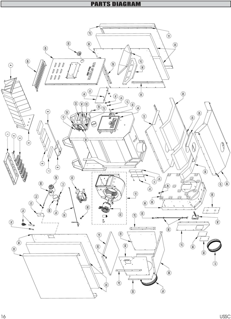
17 PARTS DIAGRAM AND LIST Key Description Part # Qty 1 Grate Retainer Shaker Bar Shaker Grate Section Front Liner Back Liner Full Firebrick (4-1/2 wide x 9 tall x 1-1/4 thick) Half Firebrick (2-1/4 wide x 9 tall x 1-1/4 thick) Slide Baffle Baffle Rod Inside Cover Plate Gasket, Water Coil Cover C #12 x 3/4: Tek Screw C Carriage Bolt, 1/4-20 x 1-1/4 Long Smoke Door Clip Kep Nut, 1/ Smoke Curtain Door Handle N/S Lock Nut, 1/ N/S Washer Feed Door Latch Feed Door Assy. (w/rope Gasket) Shaker Handle Bracket, Shaker Handle Ash Door Latch Ash Pan Carry Handle Ash Door Assy. (w/rope Gasket) Draft Cap Outer Side Wall, Left Panel-L, inner Cabinet Clip, Outer Wall Bracket, Alignment Cabinet Door Stop Insulation, Cabinet Side Outer Side Wall, Right Panel-R, inner Cabinet Harness, 2 Circuit Plug Filler, Top Hood, Front Assembly, Cabinet Back Insulation, Back Insulation Holder Key Description Part # Qty 41 Inner Top Insulation, Top-Front Insulation, Top-Middle Insulation, Top-Rear Mount, Flue Outlet Weldment, Cabinet Top D-Ring Clip Bottom Intake Assembly, Cabinet Door Latch, Cabinet Door CFM Blower Assembly N/S 1/4-20 x 3/4 Self Tapping Screw N/S Washer Blower Motor Fan Center Assembly Honeywell Limit Control Harness, 3 Circuit Plug /8 Snap Bushing-Heyco (BLK) Cable Chase Gasket, Access Panel Probe Access Panel Cover, Water Coil Bottom, Blower Box /4 Bushing, Heyco Right Side, Blower Box Left Side Assy., Blower Box Back, Blower Box Top, Blower Box MTG. Bracket, Blower Box Motorized Natural Draft (MND) Assembly N/S MND Motor Draw Band /4-20 x 1 Hex Bolt /4-20 Lock Nut Plate, Electrical Connection Strain Relief Bushing Hook, Handle Handle, Separable Stub Collar Stub Collar N/S #10 x 3/4 Tek Screw w/ Bonded Neoprene Washer N/S = Not Shown USSC 17

18 PARTS DIAGRAMS AND LISTS - MOTORIZED DRAFT KIT 4 Key Description Part # Qty 1 Weldment, Draft Tube Spin Draft /8-16 x 2-1/2 Carriage Bolt Lock Nut, 3/ Actuator, Motorized Draft Tube, Flipper Flipper #8 x 1/2 Tek Screw, Hex Head Strain Relief Power Supply Cord in. 11 Male, Tyco Terminal USSC

19 PARTS DIAGRAMS AND LISTS - FAN CENTER CONTROL Key Description Part # Qty 1 Electrical Box Cover Electrical Box Body Switch, 3-Position Harness, 6 Circuit Receptacle Harness, 3 Circuit Receptacle Harness, 2 Circuit Receptacle Transformer, Fan Center Strain Relief Power Supply Cord #10 x 1/2 Sheet Metal Screw 83172Z Washer, Internal tooth, # USSC 19

20 NOTES 20 USSC

21 5 1 ACCESS PANEL REAR WALL OF FIREBOX DOMESTIC HOT WATER COIL KIT - OPTIONAL This Furnace will accept the installation of a Domestic Hot Water Coil Kit. The U.S. Stove kit is a 1124 Water Coil and it may be purchased from your local dealer. 1. Remove the access panel on the rear of the furnace enclosure. 2. With a utility knife, cut away a section of the insulation directly behind the access panel. 3. Remove the cover plate from the rear of the furnace firebox. 4. Place one nut on each end of the water coil and thread each nut up to the end of the threads on the coil. 5. Insert the coil through the holes from the inside of the firebox. Install a gasket, washer and nut onto each end of the water coil. Tighten the nuts down securely to insure an air tight seal. The installation is now ready to be plumbed to your existing hot water system. Choose one of the three methods described in the Hot Water Coil instructions. 6. Remove knockouts from the access panel and re-attach to the furnace enclosure. Have a qualified plumber connect your domestic hot water pipe to the coil with the appropriate fittings. 1. NUT 2. WASHER 3. GASKET DOMESTIC HOT WATER COIL TURN INSIDE NUTS UP TO END OF THREADS 6 USSC 21
22 BULLETIN RC454 A GUIDE TO BURNING COAL IN YOUR FURNACE Furnaces that are capable of burning coal usually will burn both Bituminous and Anthracite coal. Anthracite is perhaps the best coal fuel because of its long even burn time, high heat output, and cleanliness which make it a good choice for the home. However, keep in mind it is a much more difficult fuel to use, requires more care and patience, is not so widely available, and is usually much more expensive than Bituminous. SIZE OF COAL: Most sizes of Bituminous Coal will work in a coal furnace; for best results we recommend large nut coal to small egg coal (1-3/4 diameter to 4 diameter). When burning Anthracite, use egg or broken with sizes between 2-5/16 thru 4-3/8. Note that it is important to the long life of your stove to buy coal which has been sized and cleaned. Cleaning insures removal of rocks and other minerals. Never use coal smaller than 1 or larger than 5 in diameter. Small sized coal will smother the fire. Too large a size of coal will not burn well. STOVE OPERATION: All coal fires should be started with wood which will allow the fire to get hot enough to ignite the coal. The best ignition fires utilize dry pine or other resinous soft woods as kindling, with hard wood (oak, hickory, ash) added to increase the heat prior to addition of the coal. Before starting the fire, open the stove pipe damper (if equipped), turn the thermostat to high, open the ash pit door and feed door, place newspaper and finely split kindling on the grate, light the paper, add larger hard wood after the kindling is burning brightly. CAUTION: Never use gasoline, lantern fuel, kerosene, charcoal lighter fluid, or other flammable liquids to start or freshen up a fire in any heater. Place the larger pieces of wood on the fire so that they are slightly separated and form a level for the addition of coal. It will take 10 to 20 minutes before this wood is thoroughly ignited. Adding coal too soon will cut the air supply and smother the fire. BURNING BITUMINOUS: Once your kindling and wood fire has produced a bed of well established coals, start adding coal in layers allowing each to ignite before adding more. Bituminous has a high volatile content and, as a result, should be fired with the conical method - with the highest portion of your fire bed in the center of the firebox. The first flames will be long and generally orange or yellow and produce quite a bit of smoke. As the gases burn off the flames become shorter, change color and produce less smoke. Once the fire is WELL ESTABLISHED add coal to the center of the firebox forming the cone. Burning in this fashion allows heat to drive off the volatile gases, and turbulence created increases the burn efficiency. There will have to be some experimenting with the individual setup as no two chimney s or installations are going to be the same. Just remember to allow enough air to enter the firebox and keep the stove pipe damper open so that volatiles are properly burned. Before refueling, take the time to break up the cone a little with a poker, especially if it has caked over or formed a crust. But, be careful not to mix the coal as this increases the chances of forming clinkers. When shaking the grate(s) be gentle. Just a few short movements - a couple of cranks - is better than a lot of agitation. The objective is to remove a small amount of the ashes without disturbing the fire. Stop when you see a glow in the ashes or the first red coals fall into the ash pan. Excessive shaking wastes fuel and can expose the grate(s) to very high temperatures which can cause warpage or burnout. For overnight operation (long duration burn time) shake the fire and add coal, retaining the center cone. Once the volatiles are burned off, close the feed door and adjust the stove pipe damper, if equipped. Then adjust the thermostat to the desired heat level. More MAINTENANCE will be needed with bituminous coal than with anthracite coal as more soot will collect on heating surfaces and in pipes, requiring more frequent cleaning. ANTHRACITE: Add a thin layer of coal (preferably smaller chunks) to the wood fire, being careful not to disturb it too much or cut off the draft. Then, add a second heavier layer after the coal is ignited and burning well. If necessary, add a third layer to bring the coal up to the top of the front liner (not above!). Be sure to close the ash door. Before adding further fuel, be sure to leave a red spot of glowing coals in the center of the firebox to insure that the fire has not been smothered and to help ignite the gases given off by the new charge. A deep charge will give a more even heat and a longer fire, but it may take one to two hours before the whole bed is fully ignited. 22 USSC
23 BULLETIN RC454 A GUIDE TO BURNING COAL IN YOUR FURNACE When the fire is well established and the room is becoming warm, partially close the dampers. Some experimenting will have to take place with each particular setting of all dampers and controls as the chimney provides the draft necessary to not only exhaust the smoke, but to pull combustion air into the heater as well - and no two chimney s perform the same. Under ideal draft conditions, one should be able to turn the secondary air supply below the feed door (some models) to a near closed position - but leave the ash pit damper at least partially open to prevent the fire from going out. Adjust the stove pipe damper to reduce the draft on the fire. With anthracite there will be short blue flames above the coal, except when the fire is started or a new charge is added. If, however, there is no flame then the fire needs more air from the bottom (unless it is near the end of its burn cycle and needs to be recharged). Only when the coal is burned down to half its original depth it is time to add fresh coal. When doing so, open the stove pipe damper and turn the thermostat damper to high, which will allow the fire to burn off any accumulated gases. Open the feed door, and with a small rake, hoe, or hooked poker pull the glowing coals to the front of the firebox. Try not to disturb the fire too much. Next, add a fresh charge to the back being careful not to seal off the top. Close the feed door, but leave the spin damper (or thermostat) open for a few minutes until the volatile gases have burned off. It is not necessary to shake down the ashes each time you refuel the furnace. Experience will be your best teacher. BANKING THE FIRE: For extended operation, such as overnight, the fire will need to be banked. To do so heap coal up along the sides and back of the firebox so that the fire gradually burns it over a longer period of time. The intensity of the fire will also be reduced without letting it go out. Follow the same procedure as for refueling. If possible, avoid shaking, as a heavier layer of ash will help reduce the intensity of the fire during this time. After loading, let the fire establish itself for about 30 minutes. Then close your damper and automatic control to the point where the house does not become too cold. It is important that you begin banking early enough before retiring or leaving that you can make necessary adjustments after the fire is well established. To revive a coal fire that is almost out, (1) open the ash door and stove pipe damper and close the spin damper under the door to get a good draft through the grate. (2) place a thin layer of dry coal over the entire top of the fire. DO NOT POKE OR SHAKE THE FIRE AT THIS TIME! (3) after the fresh coal has become well ignited shake the grate (just a little), refuel. DO NOT burn coke, charcoal, high volatile bituminous coal, sub bituminous, lignite or cannel coal (sometimes called channel coal or candle coal). NEVER burn wax or chemically impregnated sawdust logs - their intended use is for fireplaces only. NEVER fill the stove or furnace above the firebrick or cast iron liner. USSC 23
BUILT-IN DISHWASHER INSTALLATION INSTRUCTIONS
 BUILT-IN DISHWASHER INSTALLATION INSTRUCTIONS PLEASE READ COMPLETE INSTRUCTIONS BEFORE YOU BEGIN LEAVE INSTALLATION INSTRUCTIONS AND USER'S GUIDE WITH OWNER ALL ELECTRIC WIRING AND PLUMBING MUST BE DONE
CROWN BOILER COMPANY BWF SERIES BOILER CATEGORY I VENT KIT INSTALLATION AND OPERATING INSTRUCTIONS
 CROWN BOILER COMPANY BWF SERIES BOILER CATEGORY I VENT KIT INSTALLATION AND OPERATING INSTRUCTIONS WARNING Improper installation, adjustment, alteration, service, or maintenance of this product can cause
Cooktop Low-Profile Ventilation Hoods
 INSTALLATION GUIDE Cooktop Low-Profile Ventilation Hoods Contents Wolf Cooktop Low-Profile Ventilation Hoods........ 3 Cooktop Low-Profile Hood Specifications.......... 4 Cooktop Low-Profile Hood Installation............
USER S, MAINTENANCE and SERVICE INFORMATION MANUAL
 CONTENTS SAFETY INFORMATION................ 2 FOR YOUR SAFETY....................... 2 SYSTEM OPERATION.................. 2 THERMOSTATS........................... 2 INTERMITTENT IGNITION DEVICE...........
MODEL 300505 INSTALLATION INSTRUCTIONS
 WWW.BURCAM.COM 2190 Boul. Dagenais West TEL: 514.337.4415 LAVAL (QUEBEC) FAX: 514.337.4029 CANADA H7L 5X9 info@burcam.com Your pump has been carefully packaged at the factory to prevent damage during shipping.
COMMERCIAL COOKING HOODS, VENTILATION & FIRE SUPPRESSION SYSTEM GUIDELINES AND PROCEDURES
 COMMERCIAL COOKING HOODS, VENTILATION & FIRE SUPPRESSION SYSTEM GUIDELINES AND PROCEDURES These guidelines are to be used for ALL commercial cooking hoods, ventilation systems and related fire suppression
SL280UHV SERIES GAS FURNACE WARNING
 2010 Lennox Industries Inc. Dallas, Texas, USA 506677 01 11/2010 Supersedes 506409 01 SL280UHV SERIES GAS FURNACE Litho U.S.A. FIRE OR EXPLOSION HAZARD. Failure to follow safety warnings exactly could
INSTALLATION AND OPERATIONS GUIDE FOR GRAND CANYON GAS LOG SYSTEMS
 INSTALLATION AND OPERATIONS GUIDE FOR GRAND CANYON GAS LOG SYSTEMS Installation and service must be provided by a qualified installer, service agency or gas supplier Grand Canyon Gas Logs, logs are made
Installation Instructions
 VentilAire IV Whole-House Fresh Air Supply System Installation Instructions 914228 Flat Roof Kit 914229 Sloped Roof Kit 5" x 11' Class I Insulated Flexible Duct Plastic Clamps (2) Metal Clamps (2) Ceiling
Installation Instructions For Slider Casement Air Conditioners
 Installation Instructions For Slider Casement Air Conditioners NOTE: These instructions describe installation in a typical wood framed window with a wood SLIDE-BY sash, or installation in a metal CASEMENT
Wood Heat The Safe Way
 Wood Heat The Safe Way A general guide to the safe and efficient installation and operation of wood heating appliances. Prepared by Farm Bureau Insurance in collaboration with Lansing Community College
1 DESCRIPTION OF THE APPLIANCE
 1 DESCRIPTION OF THE APPLIANCE 1.1 INTRODUCTION The cast iron SF boilers are a valid solution for the present energetic problems, since they can run with solid fuels: wood and coal. These series of boilers
Owners & Installation Manual for the Sheridan, Mountainair, Pine Valley and Old Forge Ceiling Fan Family
 Owners & Installation Manual for the Sheridan, Mountainair, Pine Valley and Old Forge Ceiling Fan Family Part of the Kiva Lighting Family Custom Lighting and Fans Since 1992 1312 12th St NW Albuquerque,
from Farm Bureau Insurance
 A GENERAL GUIDE TO THE SAFE AND EFFICIENT INSTALLATION AND OPERATION OF WOOD HEATING APPLIANCES from Farm Bureau Insurance Take Extra Care Years ago, when wood heating was more the norm than the exception,
INFRARED QUARTZ WALL HEATER
 INFRARED QUARTZ WALL HEATER MODEL NO: IQ2000 PART NO: 6939004 MOUNTING & OPERATION INSTRUCTIONS GC0715 INTRODUCTION Thank you for purchasing this CLARKE Infrared Wall Heater. Before attempting to use this
IMPORTANT SAFETY INSTRUCTIONS WARNING READ AND SAVE THESE OPERATING AND SAFETY INSTRUCTIONS BEFORE USING THIS HEATER.
 THERMAWAVE CERAMIC HEATER Model HZ-850 Series Model HZ-860 Series IMPORTANT SAFETY INSTRUCTIONS WARNING READ AND SAVE THESE OPERATING AND SAFETY INSTRUCTIONS BEFORE USING THIS HEATER. Warning Failure to
PRE-ASSEMBLED INSTALLATION INSTRUCTIONS FOR PACB SERIES COAL FIRED OVENS
 PRE-ASSEMBLED INSTALLATION INSTRUCTIONS FOR PACB SERIES COAL FIRED OVENS OVENS MANUFACTURED BY: EARTHSTONE OVENS-6717 SAN FERNANDO RD GLENDALE CA 91201 TELEPHONE: 800-840-4915 818-553-1134 FAX: 818-553-1133
Gas-Fired, Residential Storage Type Water Heaters
 Consulting, Resource, Education, Training, and Support Services for Home Inspectors A candle loses no light when it lights another candle. Gas-Fired, Residential Storage Type Water Heaters Most inspectors
Troubleshooting Draft Problems in Chimneys
 Troubleshooting Draft s in Chimneys Draft is the difference in pressure between the inside of the chimney and inside of the house. This is affected mostly (though not completely; see info on fans for example)
Installation Instructions
 READ BEFORE INSTALLING UNIT For Slider Casement Air Conditioners To avoid risk of personal injury, property damage, or product damage due to the weight of this device and sharp edges that may be exposed:
SECTION 23 81 03 - PACKAGED ROOFTOP AIR CONDITIONING UNITS NON-CUSTOM
 SECTION 23 81 03 - PACKAGED ROOFTOP AIR CONDITIONING UNITS NON-CUSTOM PART 1 - GENERAL 1.1 SUMMARY A. Section Includes: 1. Packaged rooftop air conditioning unit (5 tons and smaller). 2. Roof curb. 1.2
ADDING AN ELECTRIC AUXILIARY FAN TO RADIATOR STACK ON 03 ALPINE COACH
 ADDING AN ELECTRIC AUXILIARY FAN TO RADIATOR STACK ON 03 ALPINE COACH The original design of the 03 Alpine Coaches (and perhaps other years as well) did not include any kind of engine fan engage mechanism
GNOME PELLET E.I. Pellet Heater Owner's Manual Installation and Operating Instructions. Please read this entire manual before installation.
 Pellet Heater Owner's Manual Installation and Operating Instructions Please read this entire manual before installation. Save these instructions. SAFETY NOTICE HEATER MUST BE PROPERLY INSTALLED AND MAINTAINED
Float and Thermostatic Traps Series H, C and X
 Hoffman Specialty Installation & Maintenance Instructions HS-(E) and Thermostatic Traps Series H, C and X Series C & NPT Series C NPT Series X NPT Series C NPT Series H Ratings Maximum Max. Operating NPT
CARING FOR YOUR WATER HEATER
 http://waterheatertimer.org/troubleshoot-rheem-tankless-water-heater.html Water Heater Inspections CARING FOR YOUR WATER HEATER Venting System (Direct Vent Only) The venting system should be inspected
5800 Temperature Sensor Cable Assembly
 5800 Temperature Sensor Cable Assembly Removal and Replacement Instruction Sheet #60-4702-070 Revision D, January 14, 2013 Overview The 5800 has two refrigeration temperature sensors, one attached to the
GENUINE PARTS INSTALLATION INSTRUCTIONS
 GENUINE PARTS INSTALLATION INSTRUCTIONS DESCRIPTION: Illuminated Kick Plate APPLICATION: Rogue (2011) PART NUMBER: 999G6 GX010 KIT CONTENTS: Item A B C G H QTY 1 1 1 D 1 E 1 F 3 15 6 Description Kick Plate,
OVEN PARTS For Models:GSC308PJB05, GSC308PJQ05, GSC308PJT05, GSC308PJS05 (Black) (White) (Biscuit) (Black Stainless)
 (White) (Biscuit) (Black Stainless)") OVEN PARTS 30" BUILT IN ELECTRIC COMBO SENSOR/SC (GOLD LINE) 3 05 Litho In U.S.A. (cre) 1 Part No. Rev.A OVEN PARTS 1 Literature Parts 4455994 Installation Instructions Use & Care Guide 8300346 Microwave
OVEN PARTS 30" BUILT IN ELECTRIC COMBO SENSOR/SC (GOLD LINE) 3 05 Litho In U.S.A. (cre) 1 Part No. Rev.A OVEN PARTS 1 Literature Parts 4455994 Installation Instructions Use & Care Guide 8300346 Microwave
UB1 AIR CONDITIONING UNIT INSTALLATION INSTRUCTIONS
 UB1 AIR CONDITIONING UNIT INSTALLATION INSTRUCTIONS INSTALLATION INSTRUCTIONS: Carefully read these instructions before installing your new air-conditioner. AUSTRALIAN AUTOMOTIVE AIR AL00500054E 1 Table
Andersen Electric Window Opener for Andersen Awning and Roof Windows
 W A Electric Window Opener Electric Window Opener for Awning and Roof Windows Congratulations! You have just purchased one of the many fine products. For ease of installation and continued enjoyment of
NOTE! READ INSTRUCTIONS FULLY BEFORE INSTALLING OR OPERATING.
 INSTALLATION AND OPERATION GUIDE FOR HARGROVE GAS LOGS PROPANE GAS ADEQUATE FIREPLACE VENTILATION IS REQUIRED FOR SAFETY. GAS LOGS MUST BE INSTALLED BY PERSONNEL QUALIFIED FOR INSTALLING GAS APPLIANCES.
IMPORTANT INSTRUCTIONS & OPERATING MANUAL. Houston 50 Inch Electric Wall Mounted Fireplace Black / White
 IMPORTANT INSTRUCTIONS & OPERATING MANUAL Houston 50 Inch Electric Wall Mounted Fireplace Black / White Model Number:MFE5050BK Model Number:MFE5050WH Read these instructions carefully before attempting
Boiler Plan II Table of Contents
 Cover Page Table Of Contents Introduction Parts List Additional Materials Assembly instructions Drawings 1-15 Boiler Plan II Table of Contents Introduction This will be a very rewarding project, if you
Your safety and the safety of others are very important.
 NATURAL GAS TO PROPANE CONVERSION KIT 090 INSTALLATION INSTRUCTIONS FOR ALTITUDES 0 -,00 FT. ONLY PROPANE CONVERSION KIT SAFETY... INSTALLATION REQUIREMENTS... Tools and Parts... LP Gas Requirements...
OASIS-PLUS 120V READ ALL INSTRUCTIONS BEFORE OPERATING READ ALL INSTRUCTIONS BEFORE OPERATING OZONE IS A POWERFUL OXIDIZER AND MUST BE USED WITH CARE
 OASIS-PLUS 120V INFORMATION & OPERATING INSTRUCTIONS READ ALL INSTRUCTIONS BEFORE OPERATING READ ALL INSTRUCTIONS BEFORE OPERATING OZONE IS A POWERFUL OXIDIZER AND MUST BE USED WITH CARE 56041852 WARNING:
I N S T A L L A T I O N I N S T R U C T I O N S F O R T H E H i l k o i l Energy S aving Hot Water Kit
 I N S T A L L A T I O N I N S T R U C T I O N S F O R T H E H i l k o i l Energy S aving Hot Water Kit IMPORTANT: These installation instructions are meant to be used as a guide for woodstove owners and
JANUS INTERNATIONAL CORPORATION INSTALLATION INSTRUCTIONS Pantheon Mini Operator
 JANUS INTERNATIONAL CORPORATION INSTALLATION INSTRUCTIONS Pantheon Mini Operator The Janus Pantheon mini operator does not typically require the provision of any additional site requirements other than
MBSAW. Meat Cutting Band Saw With Meat Grinder Assembly & Operating Instructions
 06/2011 MBSAW Meat Cutting Band Saw With Meat Grinder Assembly & Operating Instructions READ ALL INSTRUCTIONS AND WARNINGS BEFORE USING THIS PRODUCT. This manual provides important information on proper
HOW MUCH FUEL DOES A GAS STOVE CONSUME AND HOW MUCH DOES IT COST TO OPERATE?
 WHAT IS A BTU? The standard energy measurement is the BTU (British Thermal Unit). Each BTU unit is determined by the amount of thermal energy required to raise the temperature of one pound of water by
SIBIR MANUAL V110 KE. English page 5 RKE - 1D 822 70 66-02
 SIBIR MANUAL RKE - 1D V110 KE English page 5 822 70 66-02 2 1 A. Flue tube E. Adapter I. Thermostat B. Flue baffle F. Burner base J. Lever arm C. Control knob G. Lamp glass D. Fuel gauge H. Lamp glass
15GAL STEEL OIL DRAIN WITH 110V PUMP
 15GAL STEEL OIL DRAIN WITH 110V PUMP OWNER S MANUAL WARNING: Read carefully and understand all ASSEMBLY AND OPERATION INSTRUCTIONS before operating. Failure to follow the safety rules and other basic safety
Electric Fryers Instruction Manual Models: 8047D, 8048D, 8049D, 8050D, 8051D 8066, 8068, 8068FL, 8073, 8073BF and 8075
 Part No. 89047 Electric Fryers Instruction Manual Models: 8047D, 8048D, 8049D, 8050D, 8051D 8066, 8068, 8068FL, 8073, 8073BF and 8075 Cincinnati, OH 45241-4807 USA ELECTRIC FRYER SAFETY PRECAUTIONS Installation
VOYAGER 570G. 744A Sprayer Control
 VOYAGER 570G 744A Sprayer Control U S E R M A N U A L U S E R M A N U A L Table of Contents CHAPTER 1 - INTRODUCTION...1 SYSTEM CONFIGURATIONS...1 KIT CONTENTS...3 CONTROL HOUSING ASSEMBLY...5 CHAPTER
American Fireglass Outdoor Fire pit kit information. General instructions/warnings for outdoor gas pan and burner systems
 American Fireglass Outdoor Fire pit kit information General instructions/warnings for outdoor gas pan and burner systems We strongly recommend that our burner products be installed by a licensed and certified
http://waterheatertimer.org/troubleshoot-rheem-tankless-water-heater.html
 http://waterheatertimer.org/troubleshoot-rheem-tankless-water-heater.html TECHNICAL SERVICE DEPARTMENT Removal, Cleaning, & Reinstallation of the Burner Assembly For models 74 & GT199 Required tools -
Installation Instructions
 Installation Instructions For Use with PXPV230, PXPV265, PXPD230, and PXPD265 models Attention! - Please read these instructions completely before attempting installation. Always unplug the power supply
SunMaxx Solar Filling Station Operating Instructions
 SunMaxx Solar Filling Operating Instructions Content 1. Declaration of conformity... 2 2. Introduction... 2 3. Transportation and unpacking... 4 4. Mounting and commissioning... 5 5. End of operation...
ELECTRIC KNIFE SHARPENER
 PRODUCT MANUAL- M109 MODEL 401 ELECTRIC KNIFE SHARPENER Please read thoroughly before operation and keep for future reference Model 401 Knife Sharpener Specifications Model No. #401 Power Requirements
DC REFRIGERATORS 12/24 VOLTS INSTALLATION AND OWNER S MANUAL
 DC REFRIGERATORS 12/24 VOLTS INSTALLATION AND OWNER S MANUAL Service Information If service or parts are required, contact the nearest Norcold Service Center. To find an authorized Norcold Service Center
OVEN PARTS For Models:GMC305PDB07, GMC305PDQ07, GMC305PDT07, GMC305PDS07 (Black) (White) (Biscuit) (S.Steel)
 (White) (Biscuit) (S.Steel)") OVEN PARTS 30" BUILT IN ELECTRIC COMBO SENSOR/SC (GOLD LINE) 7 03 Litho In U.S.A. (cre) 1 Part No. OVEN PARTS NOTE: The screws and nuts required to attach a part are listed immediately following that part.
OVEN PARTS 30" BUILT IN ELECTRIC COMBO SENSOR/SC (GOLD LINE) 7 03 Litho In U.S.A. (cre) 1 Part No. OVEN PARTS NOTE: The screws and nuts required to attach a part are listed immediately following that part.
Fire Damage. To Help Prevent. a Guide
 a Guide To Help Prevent Fire Damage Fire damage in your home can be costly and emotionally devastating. The damage caused by the flames and smoke can destroy a lifetime of memories in a matter of minutes.
Roof Top Air Conditioner INSTALLATION AND OPERATING INSTRUCTIONS
 Roof Top Air Conditioner INSTALLATION AND OPERATING INSTRUCTIONS Ducted System RECORD THIS UNIT INFORMATION FOR FUTURE REFERENCE: Model Number: Serial Number: Date Purchased: This manual must be read and
UHIR Series. Horizontal or Vertical Mounting Industrial / Commercial Electric Unit Heater. Owner s Manual
 UHIR Series Horizontal or Vertical Mounting Industrial / Commercial Electric Unit Heater Owner s Manual This manual covers installation, maintenance and repair parts. Read carefully before attempting to
Guidelines for Earthquake Bracing Residential Water Heaters
 Guidelines for Earthquake Bracing Residential Water Heaters Department of General Services Division of the State Architect In accordance with the Health and Safety Code Section 19215, the Division of the
FREESTANDING CLEAN AIR WOODBURNER
 Please read this booklet and keep for future reference for the safe installation of your: FREESTANDING CLEAN AIR WOODBURNER This fire conforms with Ecan Requirements All installations must be in accordance
Figure 22: Typical Individual Venting. Figure 21: Single Water Heater Venting
 ING THE WATER HEATER The purpose of venting a gas or oil-fired water heater is to completely remove all products of combustion and to vent gasses to the outside air without condensation in the vent or
specializing in AIR CONDITIONING, PARTS AND SYSTEMS for your classic vehicle PERFECT FIT IN-DASH HEAT/ COOL/ DEFROST 1967-72 CHEVROLET PICKUP
 specializing in AIR CONDITIONING, PARTS AND SYSTEMS for your classic vehicle PERFECT FIT IN-DASH HEAT/ COOL/ DEFROST 1967-72 CHEVROLET PICKUP CONTROL & OPERATING INSTRUCTIONS The controls on your new Perfect
OWNER S MANUAL Table Tennis Table Patent Pending
 OWNER S MANUAL Table Tennis Table Patent Pending Be sure to write your model number and serial number here for future reference. You can find these numbers printed on the bottom of the table. MODEL # T8179
Portable Air Conditioner
 Portable Air Conditioner Owner's Manual Model:3 in 1 12,000 Btu/h Series 3 Please read this owner s manual carefully before operation and retain it for future reference. CONTENTS 1. SUMMARY...1 2. PORTABLE
OWNER S MANUAL FORCE 10 MARINE COMPANY 23080 HAMILTON ROAD RICHMOND, BC CANADA V6V 1C9 TEL: (604) 522-0233 FAX: (604) 522-9608
 522-0233 FAX: (604) 522-9608") Electric Water Heater OWNER S MANUAL FORCE 10 MARINE COMPANY 23080 HAMILTON ROAD RICHMOND, BC CANADA V6V 1C9 TEL: (604) 522-0233 FAX: (604) 522-9608 If your water Heater is Damaged or you have questions
Electric Water Heater OWNER S MANUAL FORCE 10 MARINE COMPANY 23080 HAMILTON ROAD RICHMOND, BC CANADA V6V 1C9 TEL: (604) 522-0233 FAX: (604) 522-9608 If your water Heater is Damaged or you have questions
Installation and Troubleshooting Instructions for Electric Tankless Residential Water Heaters.
 Model Number: Serial Number: Information Manual Installation and Troubleshooting Instructions for Electric Tankless Residential Water Heaters. ATTENTION: IF YOU ARE NOT A LICENSED PLUMBER OR A LICENSED
THREE. Heating and Cooling
 THREE Heating and Cooling 17 Condensation Drain Line The line that drains condensed moisture away from your heating and/or cooling unit needs periodic maintenance. If your unit is located in the attic,
Table of Contents. www.hunterfan.com. What to Expect with. Preparation. Tools Needed. Wiring. Hanging the Fan. Blades. Motor Housing.
 www.hunterfan.com Table of Contents What to Expect with Your Installation 30 inches Hanging the Fan Wiring 8 Maintenance, Operation & Cleaning Light Kit 13??? 14 1 9 Troubleshooting 11 5 Blades Motor Housing
- 2 - IMPORTANT SAFETY REMINDERS
 USER MANUAL IMPORTANT SAFETY REMINDERS This appliance should only be used for domestic cleaning, as described in this user guide. Please ensure that this guide is fully understood before operating the
INSTALL INSTRUCTIONS KK-C-HVAC-1 HVAC UNIT 2003-2014 CHEVROLET/GMC VANS FOR
 INSTALL INSTRUCTIONS KK-C-HVAC-1 HVAC UNIT 2003-2014 CHEVROLET/GMC VANS FOR (For NEW 2007 ALL WHITE KWIK-KITS ONLY) Warning do not attempt to install A/C units unless you are experienced with servicing
USER INSTRUCTIONS FOR GET PORTABLE 12k BTU AIR CONDITIONER MODEL No. GPACU12HR
 USER INSTRUCTIONS FOR GET PORTABLE 12k BTU AIR CONDITIONER MODEL No. GPACU12HR CONTENTS Introduction Safety Notes Identification of parts Installation instructions Operation instructions Maintenance Troubleshooting
Portable Air Conditioner. OWNER S MANUAL Read these instructions before use. Model: MF08CESWW. Voltage rating: 115V~60Hz Power rating : 800W
 MODE ALARM Portable Air Conditioner OWNER S MANUAL Read these instructions before use 8 Model: MF08CESWW Voltage rating: 115V~60Hz Power rating : 800W Customer Support : 1-800-474-2147 For product inquiries
Introduction. Safety Guidelines. Part Numbers. Operation and Maintenance Manual. Operation and Maintenance Manual
 Operation and Maintenance Manual Introduction Read all instructions thoroughly. Installation of the OilTector must comply with all Federal, State and Local Codes, Regulations and Practices. The OilTector
heating 3 & cooling heating and cooling 2010 PulteGroup, Inc. All Rights Reserved.
 3 & cooling 17 heating 2010 PulteGroup, Inc. All Rights Reserved. condensation The line that drains condensed moisture away from your heating and/or cooling unit needs periodic maintenance. Air conditioning
Time needed: ~3h for lid replacement only. Add 1h for operation harness in lid and ~2h more for installing drive unit and cable harness in trunk.
 DIY for replacing trunk lid and/or retrofitting electrical operation of trunk lid. This document is meant to be a support and give advice on the procedure but I will take no responsibility for any damage
One Year Warranty. Stock U.S. # of Volts Weight CONN. Height Dia. Watts # GAL. Elements INS. Inches NATURAL GAS* Six Year Warranty
 One Year Warranty ELECTRIC Stock U.S. # of Volts Weight CONN. Height Dia. Watts # GAL. Elements INS. Inches Fused Ceramic Shield tank lining is corrosion-resistant for years of dependability. Adjustable
FASCINATION 700 HVLP TANNING PRO SYSTEM USER MANUAL
 FASCINATION 700 HVLP TANNING PRO SYSTEM USER MANUAL Congratulations on choosing the Fascination 700 HVLP Tanning Pro System! Your system includes the following items: 1 Fascination 700 HVLP Tanning Pro
BC & BCH SERIES INDOOR / OUTDOOR INSTALLATION
 Air Conditioning Central Heating & Cooling BC & BCH SERIES INDOOR / OUTDOOR INSTALLATION INSTALLATION AND SERVICE MANUAL 2 PROJECT: ADDRESS: MODEL: SERIAL NUMBER: INSTALLER: ADDRESS: PHONE NUMBER: INSTALLATION
Cooling system components, removing and installing
 Engine BHW Cooling system components, removing and installing Page 1 / 24 19-1 Cooling system components, removing and installing Warning! When doing any repair work, especially in the engine compartment,
Generator Transfer Switch Model # HTS15-AUTO
 Generator Transfer Switch Model # HTS15-AUTO Congratulations on your purchase of our Single Circuit Generator Transfer Switch, We hope this meets and exceeds your expectations. If at anytime you have any
Portable Air Conditioner. OWNER S MANUAL Read these instructions before use. Model: MN12CES / MN10CESWW
 Portable Air Conditioner OWNER S MANUAL Read these instructions before use 8 Model: MN12CES / MN10CESWW Voltage rating: 120V~60Hz Power rating : 1100W (MN12CES) Power rating : 900W (MN10CESWW) Customer
SBC90. Abrasive Blast Cabinet Assembly & Operating Instructions
 SBC90 Abrasive Blast Cabinet Assembly & Operating Instructions READ ALL INSTRUCTIONS AND WARNINGS BEFORE USING THIS PRODUCT. SAVE THESE INSTRUCTIONS FOR FUTURE REFERENCE. This manual provides important
BACKPACK SPRAYERS. MODEL NOS: KSP16 & KSP20 Part Nos: 3402270 & 3402275 OPERATING & MAINTENANCE INSTRUCTIONS GC04/12
 BACKPACK SPRAYERS MODEL NOS: KSP16 & KSP20 Part Nos: 3402270 & 3402275 OPERATING & MAINTENANCE INSTRUCTIONS GC04/12 INTRODUCTION Thank you for purchasing this CLARKE Sprayer, designed for use only with
Wood Pellet Stove 101
 Wood Pellet Stove 101 By Eric J. Kacvinsky Kinsman Stoves, LLC. And Brookfield Stoves & Supply With assistance from Mark D. Manley Painesville Pellet and Stove, LLC Wood pellets are made mainly of sawdust,
Odyssey of the Mind Technology Fair. Simple Electronics
 Simple Electronics 1. Terms volts, amps, ohms, watts, positive, negative, AC, DC 2. Matching voltages a. Series vs. parallel 3. Battery capacity 4. Simple electronic circuit light bulb 5. Chose the right
Before installation it is important to know what parts you have and what the capabilities of these parts are.
 INSTALLATION GUIDE Before installation it is important to know what parts you have and what the capabilities of these parts are. The Recon XZT is the smallest and most powerful gauge of its kind. With
Installation Manual. Solar Pool Heating System. Read the complete manual before beginning the installation
 Solar Pool Heating System Installation Manual Read the complete manual before beginning the installation 1. Sizing the System Visit www.techno-solis.com to size the system using the sizing calculator.
Installation Instructions for Alarm Module Kit A043F059
 Instruction Sheet 07-2013 Installation Instructions for Alarm Module Kit A043F059 1 Introduction The information contained within is based on information available at the time of going to print. In line
Across America. Wood & Coal Brochure
 Across America Wood & Coal Brochure Rev. Sep. 2011 Bay Series... A series of well built high heat performers featuring decorative side windows and full view glass door with airwash system to help keep
INSTALLATION INSTRUCTIONS for Bifold Doors (JII103)
") Thank you for selecting JELD-WEN products. Attached are JELD-WEN s recommended installation instructions for premium composite, hollow and solid core molded Bifold Doors. Bifolds are designed for fast
Thank you for selecting JELD-WEN products. Attached are JELD-WEN s recommended installation instructions for premium composite, hollow and solid core molded Bifold Doors. Bifolds are designed for fast
Trouble Shooting. Pump
 Trouble Shooting Pump Trouble Possible Cause Remedy Oil leaking in the area of water pump crankshaft Worn crankshaft seal, bad bearing, grooved shaft, or failure of retainer o-ring. Excessive play on crankshaft
woodburning stoves installation and procedures
 woodburning stoves installation and procedures REVISED AUGUST, 2006 CONFORMS TO NFPA 211-2006 Legal Disclaimer The information contained herein is not intended to be used as a guide for installation or
SELF-STEERING AXLE TABLE OF CONTENTS
 SELF-STEERING AXLE TABLE OF CONTENTS Section 1 - Introduction Section 2 - Pre-Installation Check List Section 3 - Ride Height Adjustments Section 4 - Suspension Mount Section 5 - Axle Mount Section 6 -
Portable Air Conditioner. OWNER S MANUAL Read these instructions before use. Model: MM14CCS. Voltage rating: 115V~60Hz Power rating : 1400W
 Portable Air Conditioner OWNER S MANUAL Read these instructions before use Model: MM14CCS Customer Support : 1-800-474-2147 Voltage rating: 115V~60Hz Power rating : 1400W For product inquiries or support
CAST IRON THE BASICS. Heatline - Cast Iron Radiators SMOOTH FLAT FILE TO REMOVE ANY SWARF. ONE TIME. ASSEMBLY. JOINTS SHOULD BE TIGHTENED.
 CAST IRON THE BASICS 1. DO NOT LIFT ON YOUR OWN. 2. ONLY LIFT THE RADIATOR VERTICALLY. 3. DO NOT LIFT MORE THAN 8/10 SECTIONS AT ANY ONE TIME. 4. POSITION THE RADIATOR BEFORE FINAL ASSEMBLY. 5. THIS PRODUCT
Watts Spacemaker. Sa f e t y Wa t e r He a t e r. Enclosures Stands Restraints
 Watts Spacemaker Sa f e t y Wa t e r He a t e r Installation Products Enclosures Stands Restraints Ta b l e o f Co n t e n t s / In t r o d u c t i o n / Seismic Zo n e s Table of Contents Seismic Zones
PROCEDURES PREVENTION OF ACCIDENTAL IGNITION
 Page No: 1 of 7 6.0 PURPOSE (192.751) All possible precautions shall be exercised to prevent the accidental escape and ignition of gas. Whenever possible, potential sources of ignition should be eliminated
ecomax Instructions for use Wall hung room sealed fan assisted condensing boilers For the user
 For the user Instructions for use ecomax Wall hung room sealed fan assisted condensing boilers ecomax 63/ E ecomax 68/ E ecomax 6/ E ecomax 635 E ecomax 84/ E ecomax 88/ E ecomax 835 E GB Table of contents
Owner s Guide and Installation Manual. Vancouver Model Name. 21321, 21328 Model No. English Español
 For Your Records and Warranty Assistance For reference, also attach your receipt or a copy of your receipt to the manual. Vancouver Model Name 21321, 21328 Model No. Type A Models Owner s Guide and Installation
Crawford Inspection Services C.C.B. # 76914 www.crawfordinspections.com
 Crawford Inspection Services C.C.B. # 76914 www.crawfordinspections.com Portland Area PO Box 665 West Linn, OR 97068 Ph: (503) 650-6957 Salem Area 5434 River Rd. N; #192 Keizer, OR 97303 Ph: (503) 362-5809
G26 Corp. 9721-L11 Revised 07-2001 LENNOXOEMPARTS.COM. Service Literature G26 SERIES UNITS
 Service Literature G26 SERIES UNITS G26 series units are high-efficiency upflow gas furnaces manufactured with DuralokPlust aluminized steel clamshell-type heat exchangers. G26 units are available in heating
Pet hair clipper. Model 96822. Diagrams within this manual may not be drawn proportionally.
 Pet hair clipper Model 96822 Cleaning And Operation Instructions Diagrams within this manual may not be drawn proportionally. Due to continuing improvements, actual product may differ slightly from the
Multi-Pitch Pitching Machine USER MANUAL
 Multi-Pitch Pitching Machine USER MANUAL TABLE OF CONTENTS Thank you for purchasing the Cimarron Multi-Pitch Pitching Machine. The Cimarron Multi-Pitch Pitching Machine is a high performance pitching machine
Fleck 4650. Service Manual INSTALLATION AND START-UP PROCEDURE TABLE OF CONTENTS JOB SPECIFICATION SHEET
 Fleck 4650 Service Manual TABLE OF CONTENTS JOB SPECIFICATION SHEET...1 INSTALLATION AND START-UP PROCEDURE...1 CONTROL VALVE DRIVE ASSEMBLY...2 CONTROL DRIVE ASSEMBLY FOR CLOCK...3 BYPASS VALVE ASSEMBLY...4