M272 Engine 287 HO M272 (FAH) 10/05/04
|
|
|
- Philip Harrington
- 7 years ago
- Views:
Transcription
1 M272 Engine 287 HO M272 (FAH) 10/05/04 1
")
2 Objectives Students will be able to: identify differences between M112 and M272 explain the camshaft adjusters operation identify major components of the M272 explain function of the swirl flaps explain function of the temperature management system 2

3 Contents Comparison 4 Highlights 6 Motor mechanicals 9 Oil level switch 12 Crankcase ventilation 16 Cylinder head 18 Intake manifold 29 ME Crank sensor 46 O2 sensors 49 Three way catalytic converters 50 Ignition coil 52 Mass airflow 54 Temperature management 55 Fuel tank 59 Speed sensitive power steering 64 3

4 M272 M112 Comparison M litre M litre rpm to 5000 rpm Compression Ratio 10.7 : 1 Sparkplugs per cylinder 1 ME 9.7 Coil On Plug rpm rpm Compression Ratio 10.0 : 1 Sparkplugs per cylinder 2 ME 2.8 Double ignition coils 4

5 Comparison kw 400 Red line (Dash) = M112 3 valve kw 350 Nm Blue line (solid ) = M272 4 valve power kw M Torque Nm 80 M RPM 5

6 New M272 introduced in the new SLK 171 Lets look at some highlights 6

7 M272 HighLights M112 replacement 3.5 litre displacement Counter rotating balance shaft Stiffer engine with lateral main bearing attachments 4 valve continuously variable camshafts intake and exhaust (DOHC) 7

8 M272 HighLights 90 degree V-6 Two stage Intake manifold Turbulence flaps in the intake ports ME 9.7 control unit mounted on top of engine Electrically assisted thermostat No EGR valve Both cams adjust 8

9 Lets take a look at what changed mechanically 9

10 Motor Mechanicals Based off of M112 engine Bore and Stroke increase compared to M112 Die cast aluminum crankcase Silitec coated cylinder liners Starter openings both sides of block 8 lateral main bearing bolts 10

11 Crankshaft Crankshaft lighter as compared to M112 Wider main bearings as compared to M112 used to reduce vibration Iron coated cast aluminum pistons 11

12 Balance shaft, familiar function Oil sensor, now a switch 12

13 Balance Shaft Balance shaft similar to the M112 Balance shaft rotates opposite crankshaft 13

14 Oil Level Switch Reed contact oil level switch S43 replaces B40 Only one pin of the two pin connector used S43 mounted in oil pan Chain driven oil pump Vehicle equipped with an oil level dipstick 14

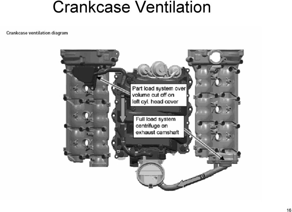
15 Partial and full load crankcase ventilation system 15

16 Crankcase Ventilation 16
17 Cylinder head 4 valves DOHC Cam adjusters 17

18 Cylinder Head New design cast aluminum cylinder heads 4 overhead camshafts (DOHC) 4 valves per cylinder, improve torque and horsepower compared to 3 valve engines Camshaft upper bearing surfaces integrated into cam housing cover Nickel coated high strength steel exhaust valves 18

19 Cylinder Head 4 Cam adjusters 4 Cam Sensors ME can detect Cam position with ignition on Intake cam is chain driven and drives exhaust cam via gear 19

20 Chain Tensioner Step type chain tensioner with internal spring Located at the lower right front engine Must be manually reset if removed Failure to preset tensioner before assembly will result in engine damage 20

21 Camshaft Timing Adjusters Vane type, oil pressure controlled adjusters Continuously variable 40 advanced for intake (from 4 BTDC to up to 36 ATDC) 40 retard for exhaust (from 30 BTDC to up to 10 ATDC) 21
22 Exhaust Cam Gear Note: Retaining nut at front timing adjuster is reverse thread 22
23 Camshaft Position Sensors 4 Hall effect sensors, one for each camshaft True Power On (TPO) sensor technology capable of detecting cam position with stationary engine Right and left camshaft signals staggered by 240 camshaft angle Signal is low in absence of a window 23
24 Impulse Wheels Four impulse wheels used on the M272 mounted on the front of each camshaft timing adjuster Each impulse wheel has a different part number The openings of the impulse wheels help ME determine the camshafts exact position Can only be used one time! If new impulse wheels are not used the pins could shear off causing massive damage to adjusters Both locating pins sheared off when reinstalled Gouging of mounting surface 24
25 Exhaust Cam Gear Exhaust Cam 2 piece gear Smaller outer gear spring loaded for noise reduction Gear must be held in place prior to disassembly Segment Ring must be replaced once removed Adjuster bolt reverse threaded 25
26 Camshaft Timing Network B6/4 Camshaft position sensor (intake left) B6/6 Camshaft position sensor (exhaust left) B6/7 Camshaft position sensor (exhaust right) B6/5 Camshaft position sensor (intake right) B11/4 Engine coolant temperature sensor B70 Crankshaft hall sensor B2/5 MAF N3/10 ME 9.7 Y49/5 Camshaft timing control solenoid (exhaust right) Y49/7 Camshaft timing control Solenoid (Intake right) Y49/4 Camshaft timing control solenoid (intake left) Y49/6 Camshaft timing control Solenoid (exhaust left) 26
27 Remove camshaft sensors Camshaft Position Align balancer (305 ) to front cover pointer Check impulse wheels stamped numbers If above line up properly cam positions are correct 27
28 Camshaft Timing Basic Position 1. Align balancer to 40 ATDC to front cover pointer 2. Front cover pointer 3. Upper camshaft marks Camshaft marks aligned to head
29 Intake Variable runners Swirl flaps 29
30 Intake Manifold Magnesium cast sectional intake manifold with integrated vacuum reservoir Variable intake runner Short runner for higher RPM Long runner for lower RPM Swirl-Flaps also added providing better fuel mixture 30
31 Intake Components 12 Intake manifold with integral vacuum reservoir 12/1 Swirl flap shaft, left cylinder bank 12/2 Swirl flap shaft, right cylinder bank 12/3 Longitudinal switch flap shaft, right cylinder bank 12/4 Longitudinal switch flap shaft, left cylinder bank 22/6 Intake manifold switchover diaphragm 22/9 Swirl valve switchover diaphragm Y22/6 Variable intake manifold switchover valve Y22/9 Intake manifold swirl flap switchover valve 31
32 Variable Length Intake Manifold Engine load over 50% from approx RPM intake flaps closed (long runner) Better cylinder filling and increased torque Above 3900 RPM switchover solenoid deactivated via ME intake flaps open (short runner) Incoming air follows short runner Unlike M112, M272 has two diaphragm actuators Vacuum applied Long runner No Vacuum applied Short runner 32
33 Intake Functional Diagram A Long runner B Short runner 1- Switchover flaps 12 Intake manifold with integral vacuum reservoir B2/5 Hot film mass airflow sensor 22/6 Intake manifold switchover diaphragm Y22/6 Variable intake manifold switchover valve M16/6 Throttle valve actuator B70 Crankshaft hall sensor N3/10 ME
34 Swirl Flaps Under certain operating conditions intake air is swirled via swirl flap for improved mixture process B28/9 Vacuum diaphragm driven by ME controls flap position Swirl flap position sensors (hall sensors) monitor 2 magnets attached to swirl flap actuating shafts to determine flap position (activated/not activated) Swirl flap position sensors B28/10 Sensors located at rear of intake manifold 34
35 Swirl Flaps A = Non swirl not active B = Swirl active 35
36 Swirl Flaps 36
37 Swirl Flap Operating Parameters 37
38 Swirl Flap Functional Diagram 12 Intake manifold 1 Swirl flap 22/9 Aneroid capsule swirl flap Switchover B11/4 Coolant temperature sensor B70- Crankshaft hall sensor B28/9 Left intake manifold swirl flap position sensor B28/10 Right intake manifold swirl flap position sensor B2/5 Hot film mass airflow sensor M16/6 Throttle valve actuator N3/10 ME 9.7 Y22/9 Intake manifold swirl flap switchover valve A Swirl flap recessed (no swirl) B Swirl flap outward (swirl) 38
39 ME 9.7 Inputs Outputs 39
40 ME 9.7 Control Module function: Cylinder sequential injection Single spark plug coil (control and diagnostics) Electronic throttle plate positioning LIN communication with alternator Turbulence flap regulation Variable length intake runner control N3/10 ME 9.7 Note: When erasing DTC s you must wait for the after run function to finish otherwise faults may remain. After run process 40
41 ME After Run Process ME performs an after run process when circuit 15 is switched off After run is determined by ME and required to store inputs After run time is typically 5 seconds but can take several minutes longer depending on various functions (temperature management, OBD, DAS3 etc.) at 176 F approx. 4 seconds, at 68 F approx. 60 seconds and at -22 F approx. 150 seconds After cycling key off, must wait ~ 150 seconds This is the period in which the fault memory is over-written 41
42 ME 9.7 Inputs/Outputs Inputs Outputs 42
43 ME 9.7 Inputs/Outputs Legend A16/1 Right knock sensor A16/2 Left knock sensor B2/5 Hot film mass air flow sensor B4/3 Fuel tank pressure sensor B6/4 Left intake camshaft hall sensor B6/5 Right intake camshaft hall sensor B6/6 Left exhaust camshaft hall sensor B6/7 Right exhaust camshaft hall sensor B11/4 Coolant temperature sensor B28 Intake manifold pressure sensor B28/9 Left intake manifold swirl flap position sensor B28/10 Right intake manifold swirl flap position sensor B37 Accelerator pedal sensor B70 Crankshaft hall sensor G2 Alternator G3/3 Left O2 sensor upstream of TWC G3/4 Right O2 sensor upstream of TWC G3/5 Left O2 sensor in TWC G3/6 Right O2 sensor in TWC M16/6 Throttle valve actuator N10/1 Driver SAM N10/1kR Circuit 87 relay N10/1kS Starter relay N10/1kO Air pump relay N10/2 Rear SAM N10/2kA Fuel pump relay S40/3 Clutch pedal switch S40/5 Start enable clutch pedal switch S43 Oil level check switch M4/7 Suction fan T1/1-6 Ignition coils 1 to 6 Y10/1 Power steering pump pressure regulator valve Y22/6 Variable intake manifold switchover valve Y22/9 Intake manifold swirl flap switchover valve Y32 Air pump switchover valve Y49/4 Left camshaft intake solenoid Y49/5 Right camshaft intake solenoid Y49/6 Left camshaft exhaust solenoid Y49/7 Right camshaft exhaust solenoid 43
44 ME 9.7 Network Signals N73 EIS N15/5 Electronic selector lever module control unit A1 Instrument Cluster N47-5 ESP and BAS control unit N80 Steering column module Y3/8n4 Fully integrated transmission control unit X11/4 Diagnostic connector N93 Central gateway control unit N22 AAC control and operating unit N2/7 - Restraint systems control unit 44
45 ME 9.7 Network Signals 45
46 Crank sensor (Hall) O2 sensors Three way catalytic converters Ignition coil Mass airflow 46
47 Crank Sensor Hall effect sensor (not inductive) Output signal switches between ground and 5 volts Incremental ring gear 58 teeth (60 2) is carry over 47
48 Sensor Signals 1 - Crank angle (CKA) 2 - Ignition TDC cylinder (in firing order) 3 - Signal of crankshaft Hall sensor (B70) 4 - Rpm signal TNA 5 - Camshaft Hall sensor intake signal, left and right 6 - Camshaft hall sensor exhaust signal, left and right A = Recognition of ignition TDC of cylinder 1 - second negative signal edge of crankshaft hall sensor after the gap - Signals 5 and 6 are "LOW" - Rpm signal (4) changes from "HIGH to "LOW" 48
49 O2 Sensors Upstream wide-band O2 sensors as known from the M271 and OM648 Downstream planar type O2 sensors mounted in catalytic converter housing Three Way Catalytic Converters (TWC) G3/3 Left upstream O2 sensor G3/5 Left downstream O2 sensor 158 Catalytic converter G3/4 Right upstream O2 sensor G3/6 Right downstream O2 sensor 49
50 Three Way Catalytic Converters Two ceramic monoliths with 600 cells each Reduces Hydrocarbons (HC) Reduces Carbon Monoxide (CO) Reduces Nitrogen Oxides (NOX) Downstream O2 sensor mounted between the monoliths 50
51 O2 Sensor Networking 17 Fuel rail 158 Catalytic converter B2/5 Hot film mass airflow sensor B11/4 Coolant temperature sensor B70 Crankshaft hall sensor B37 Accelerator pedal sensor G3/3 Left upstream O2 sensor G3/5 Left downstream O2 sensor G3/4 Right upstream O2 sensor G3/6 Right downstream O2 sensor N3/10 ME 9.7 Y62 Fuel injectors 51
52 Ignition Coil Individual coil on plug Driver located inside coil not in ME 9.7 Each coil controlled separately Diagnostic information sent back to ME Bi-directional communication with ME Pin 1 batt Pin 2 ground Pin 3 ground Pin 4 control/diagnosis 52
53 Ignition Networking A16/1 Right knock sensor A16/2 Left knock sensor B6/4 Left intake camshaft hall sensor B6/5 Right intake camshaft hall sensor B6/6 Left exhaust camshaft hall sensor B6/7 Right exhaust camshaft hall sensor B2/5 Hot film mass airflow sensor B11/4 Coolant temperature sensor B70 Crankshaft hall sensor B37 Accelerator pedal sensor M16/6 Throttle valve actuator N3/10 ME 9.7 N47-5 ESP and BAS control unit T1/1 through T1/6 ignition coil for cylinders 1 to 6 Y3/8n4 - Fully integrated transmission control (VGS) control unit X11/4 Data link connector 53
54 Hot Film Mass Airflow Sensor Frequency signal from Mass Airflow to ME Integrated Intake air temperature sensor used 54
55 Temperature management Thermostat Control 55
56 Temperature Management Coolant Temperature is regulated via Me plate thermostat Regulates temperature from 185 F to 221 F (85 C to 105 C) Heating element in thermostat energized to heat thermostat 4 operating modes dependent on engine temperature and load 56
57 Temperature Management 1 To radiator 2 From engine 3 To engine A Stationary coolant (cold start) B Circuit for engine and heat exchanger C Active after 208 F (98 C), after start or ambient temp. above 82 F (28 C) D Position for max radiator operation 57
58 Temperature Management 58
59 Fuel tank Fuel pump control 59
60 Fuel Tank Magnesium cover helps protect tank Two layer steel tank with 18.4 gallon capacity In tank fuel supply system operates with 3.8 bar pressure Fuel filter with pressure regulator Returnless fuel system 60
61 Fuel Networking A Electrical line B Fuel pipe C Purge line 12 Intake manifold 17 Fuel rail 17/1 Fuel pressure reservoir 45 Fuel filler neck, with ORVR 51 Pressure gauge connection 55/2 Fuel filter 55/2a Fuel pressure regulator 3.8 bar 75 Fuel tank 76 Vent valve, except USA 77 Activated charcoal canister B4/3 Fuel tank pressure sensor M3 Fuel pump assembly (with integral fuel pump (FP)) N10/2kA Fuel pump relay N3/10 ME-SFI control unit Y58/1 Purge control valve Y58/4 Activated charcoal filter shutoff valve Y62 Fuel injection valves 61
62 Fuel Pump Control Fuel pump controlled via fuel pump relay (N10/2kA) Fuel pump Relay located in rear SAM (N10/2) Fuel pump relay energized via ME Fuel pump runs ~ 1 second after ignition on N10/2 Rear SAM N10/2kA Fuel pump relay 62
63 Fuel Supply Circuit In Tank Pressure Regulator (3.8 bar) Fuel Filter Supply Return Splash bowl Fuel Pump Fuel supply to engine 63
64 Access Point To Fuel Filter and Pump Tank Pressure Sensor Connector For pump And level sensor 64
65 Fuel Pressure Regulator Filter Pressure regulator A B C A-from pump B-return to splash bowl C-filtered fuel to engine 65
66 Fuel Level Sensor Release tangs for removal 66
67 Splash Bowl pump Swivel 2 retainers to remove pump 67
68 Fuel Pump 68
69 N3/10 ME 9.7 A1 Instrument cluster N10/2 Rear SAM B4 Fuel level sensor 75 Fuel tank 69
70 Speed Sensitive Power Steering 70
71 Speed Sensitive Power Steering Gives the customer firmer feel in steering at higher speeds and more assist for parking maneuvers at slower speeds ME 9.7 now controls functions of the Speed Sensitive Power Steering system The valve port is adjusted for steering support required for the current driving condition and is dependent on the following input signals: Engine speed Vehicle speed (Via CAN) Steering angle (Via CAN) Steering angle speed (Via CAN) 71
72 Speed Sensitive Power Steering The pressure regulator valve controls the valve port and is rigidly connected to the power steering pump It is actuated according to a performance map with a duty cycle of 10 to 90% and regulates the amount delivered to the power steering pump at between 2 and 9 liters/minute The pressure regulator valve is opened wide for ignition ON and during engine start In the case of faults on the input signals or on the pressure regulator valve, actuation is interrupted immediately and the maximum support is available from the power steering pump 72
73 Speed Sensitive Power Steering Networking B70 Crankshaft Hall sensor N3/10 ME-SFI control unit N47-5 ESP and BAS control unit N80 Steering column module Y10/1 Power steering pump pressure regulator valve 73
74 74
75 75
76 Questions? 76
E - THEORY/OPERATION
 E - THEORY/OPERATION 1995 Volvo 850 1995 ENGINE PERFORMANCE Volvo - Theory & Operation 850 INTRODUCTION This article covers basic description and operation of engine performance-related systems and components.
The 2.0l FSI engine with 4-valve technology
 Service Training Self-study programme 322 The 2.0l FSI engine with 4-valve technology Design and function The 2.0l engine is based on the tried and tested 827/113 series. Thanks to FSI technology (Fuel
Typical ECM/PCM Inputs
 Typical ECM/PCM Inputs The computer system components fall into two categories: sensors (inputs) and controlled components (outputs). Each system has sensors. Not every system has all the ones listed,
Fault codes DM1. Industrial engines DC09, DC13, DC16. Marine engines DI09, DI13, DI16 INSTALLATION MANUAL. 03:10 Issue 5.0 en-gb 1
 Fault codes DM1 Industrial engines DC09, DC13, DC16 Marine engines DI09, DI13, DI16 03:10 Issue 5.0 en-gb 1 DM1...3 Abbreviations...3 Fault type identifier...3...4 03:10 Issue 5.0 en-gb 2 DM1 DM1 Fault
Electronic Diesel Control EDC 16
 Service. Self-Study Programme 304 Electronic Diesel Control EDC 16 Design and Function The new EDC 16 engine management system from Bosch has its debut in the V10-TDI- and R5-TDI-engines. Increasing demands
Signature and ISX CM870 Electronics
 Signature and ISX CM870 Electronics Cummins West Training Center System Description General Information The Signature and ISX CM870 engine control system is an electronically operated fuel control system
Wynn s Extended Care
 Wynn s Extended Care Every car deserves to receive the very best care... especially yours. How Do You Keep Your Reliable Transportation Reliable? Count on Wynn s Because Wynn s has been caring for cars
The 1.2 ltr. 3-cylinder petrol engines
 Service. Self-Study Programme 260 The 1.2 ltr. 3-cylinder petrol engines Design and Function The two 1.2 ltr. engines mark the introduction of 3-cylinder petrol engines at Volkswagen. This pair of entry-level
Engine/Gearbox Combinations
 Engine/Gearbox Combinations Engine code letters ARV/ATY AME ATZ Displacement 1.0 ltr. 1.4 ltr. 1.4 ltr. Power output 37 kw/50 HP 50 kw/68 HP 50 kw/68 HP Engine management system Simos 3PB Simos 3PB Simos
Diagnostic Fault Codes For Cummins Engines
 Section - Diagnostic Fault Codes For Cummins Engines Applies to Engine Models T, T, QSL T, QSM, QS, QSK9, QSK, QST, QSK//8 Note: These fault codes are current at date of publication. Always refer to engine
REMOVAL AND INSTALLATION
 303-01C-1 REMOVAL AND INSTALLATION Engine Body On Special Tool(s) Adapter For 303-D043 303-D043-02 or equivalent Special Tool(s) 303-01C-1 Turbocharger Lifting Bracket 303-1266 Wrench, Fan Clutch Nut 303-214
Kobelco Extended Warranty Program. www.kobelco-europe.com
 Kobelco Extended Warranty Program www.kobelco-europe.com Kobelco Extended Warranty is a convenient, value added way to give your Kobelco customers added security and peace of mind. Benefits of the Kobelco
Lotus Service Notes Section EMR
 ENGINE MANAGEMENT SECTION EMR Sub-Section Page Diagnostic Trouble Code List EMR.1 3 Component Function EMR.2 7 Component Location EMR.3 9 Diagnostic Guide EMR.4 11 CAN Bus Diagnostics; Lotus TechCentre
6-years/75,000 miles Comprehensive coverage Subsequent Owner Warranty $100 Deductible
 LINCOLN PREMIER LIMITED WARRANTY 6-years/75,000 miles Comprehensive coverage Subsequent Owner Warranty $100 Deductible Comprehensive Coverage Because Lincoln has always been a brand you can trust and respect,
COVERING MILLIONS Preferred Protection Plan, a Service Group Company www.sgifs.com PO Box 26830, Austin, TX 78755-0800.
 COVERING MILLIONS Preferred Protection Plan, a Service Group Company www.sgifs.com PO Box 26830, Austin, TX 78755-0800. 1-877-565-0816 PPP-308 0903 rev 0408 BENEFITS New and Pre-Owned Vehicles Preferred
Note: This information obtained from internet sources and not verified- use at your own risk!!!!
 Cummins Engine Diagnostic Fault Codes for 2003 and later engines (generally for 2004 and later Alpines; see page 13 for earlier engine diagnostic codes): Note: This information obtained from internet sources
DTC Database (OBD-II Trouble Codes)
") Auto Consulting S.a.s di Cofano A. & C. Attrezzature diagnostiche Elaborazioni elettroniche Formazione tecnica DTC Database (OBD-II Trouble Codes) Definitions for generic powertrain diagnostic trouble
Auto Consulting S.a.s di Cofano A. & C. Attrezzature diagnostiche Elaborazioni elettroniche Formazione tecnica DTC Database (OBD-II Trouble Codes) Definitions for generic powertrain diagnostic trouble
ENGINE CONTROL SYSTEM
 36 ENGINE CONTROL SYSTEM DESCRIPTION The construction and functions of the new 1MZ-FE engine includes the following modifications and additions in comparison with the 1MZ-FE engine installed on the 98
Cooling system components, removing and installing
 Page 1 of 30 19-1 Cooling system components, removing and installing Notes: When the engine is warm the cooling system is under pressure. If necessary release pressure before commencing repair work. Secure
Turbocharger system components, servicing
 21-1 Turbocharger system components, servicing Engine codes: AAZ, 1Z, AHU Observe rules of cleanliness Page 21-10 Turbocharger hoses and lines, connecting Page 21-11 WARNING! Do not re-use any fasteners
Technical Service Information
 Technical Service Information COMPLAINT: CAUSE: 1996-20 DEFINITIONS When a VW/Audi vehicle is exhibiting a symptom or is in fail-safe, the technician, in many cases, is unable to communicate with the on-board
Evaporative emissions system
 just a test. Evaporative emissions system 20-48 Function description of EVAP canister system Depending upon the air pressure and ambient temperature, fuel vapor will form above the level of fuel in the
SAS light Check Engine Malfunction Indicator Lamp
 SAS light Check Engine Malfunction Indicator Lamp Here's how to do it: In car ECM Diagnostics/ECM Reset procedure: 1) Sit in the driver's seat. 2) Turn the ignition key to the ON position and wait three
6. VVT-i (Variable Valve Timing-intelligent) System
 System") 38 ENGE 1ZZ-FE ENGE 6. VVT-i (Variable Valve Timing-intelligent) System General This system controls the intake camshaft valve timing so as to obtain balance between the engine output, fuel consumption
38 ENGE 1ZZ-FE ENGE 6. VVT-i (Variable Valve Timing-intelligent) System General This system controls the intake camshaft valve timing so as to obtain balance between the engine output, fuel consumption
1/29/2008 DR70. Baja Motorsports Inc. P.O. Box 61150 Phoenix, AZ 85082 Toll Free: 888-863-2252 PART NUMBERS PRICES ARE SUBJECT TO CHANGE 1 of 43
 DR70 Toll Free: 888-863-2252 PART NUMBERS PRICES ARE SUBJECT TO CHANGE 1 of 43 CYLINDER & CYLINDER HEAD 1 DR70-001 883099044472 CYLINDER 1 1 2 DR70-002 883099044489 GASKET, CYLINDER 1 1 3 DR70-003 883099044496
Electronic Manual Gearbox
 Service. Self-Study Programme 221 Electronic Manual Gearbox Design and Function Taking the Lupo as the basis, Volkswagen has developed the world's first 3 L car that will also go into volume production.
Lotus Service Notes Section EMP
 ENGINE MANAGEMENT SECTION EMP Sub-Section Page Diagnostic Trouble Code List EMP.1 3 'Lotus Scan' Diagnostic Tool EMP.2 43 Engine Management Component Location EMP.3 45 Mechanical Throttle Setting Procedure
2003 ACCORD - Automatic Transmission Removal
 2003 ACCORD - Automatic Transmission Removal Special Tools Required Engine support hanger, A and Reds AAR-T-12566 Engine hanger balancer bar VSB02C000019 Front subframe adapter VSB02C000016 These special
ENGINE 1ZZ-FE AND 2ZZ-GE ENGINES
 ENGINE CONTROL SYSTEM 1. General The engine control system for the 1ZZ-FE and 2ZZ-GE engines have following system. System SFI Sequential Multiport Fuel Injection ESA Electronic Spark Advance IAC (Idle
Tiguan Haldex All-Wheel Drive
 Service Training Self Study Program 861803 Tiguan Haldex All-Wheel Drive Volkswagen of America, Inc. Volkswagen Academy Printed in U.S.A. Printed 3/2008 Course Number 861803 2008 Volkswagen of America,
ON-Board Diagnostic Trouble Codes
 ON-Board Diagnostic Trouble Codes The list below contains standard diagnostic trouble codes (DTC s) that are used by some manufacturers to identify vehicle problems. The codes provide below are generic
UNIT 3 AUTOMOBILE ELECTRICAL SYSTEMS
 UNIT 3 AUTOMOBILE ELECTRICAL SYSTEMS Automobile Electrical Structure 3.1 Introduction Objectives 3.2 Ignition System 3.3 Requirement of an Ignition System 3.4 Types of Ignition 3.4.1 Battery or Coil Ignition
1/29/2008 DR50. Baja Motorsports Inc. P.O. Box 61150 Phoenix, AZ 85082 Toll Free: 888-863-2252 PART NUMBERS PRICES ARE SUBJECT TO CHANGE 1 of 45
 DR50 Toll Free: 888-863-2252 PART NUMBERS PRICES ARE SUBJECT TO CHANGE 1 of 45 CYLINDER & CYLINDER HEAD Part UPC Number Description Baja Description 1 DR50-001 842645074424 CYLINDER 1 1 2 DR50-002 842645074431
EM 58. 19. REMOVE NO. 2 MANIFOLD STAY (a) Remove the bolt, nut and stay.
 Remove the bolt, nut and stay.") 57 ROVAL 1. DISCHARGE FUEL SYST PRESSURE (See page FU-9) 2. DISCONNECT CABLE FROM NEGATIVE BATTERY TERMINAL CAUTION: Wait at least 90 seconds after disconnecting the cable from the negative (-) battery
57 ROVAL 1. DISCHARGE FUEL SYST PRESSURE (See page FU-9) 2. DISCONNECT CABLE FROM NEGATIVE BATTERY TERMINAL CAUTION: Wait at least 90 seconds after disconnecting the cable from the negative (-) battery
DTC Summaries. V8 AJ26 Engine Management 1997. Refer to page 2 for important information regarding the use of this Summary.
 DTC Summaries V8 AJ26 Engine Management 1997 OBD II MONITORING CONDITIONS: When testing for DTC reoccurrence, it can be determined if the Service Drive Cycle was of sufficient length by performing a PDU
COMMON RAIL SYSTEM (CRS) SERVICE MANUAL: Operation
 SERVICE MANUAL: Operation") ISUZU ELF 4HK1/4JJ1 Engine COMMON RAIL SYSTEM (CRS) SERVICE MANUAL: Operation Issued : June 2007 Revised : July 2009 00400601EA 2009 DENSO CORPORATION All rights reserved. This material may not be reproduced
ISUZU ELF 4HK1/4JJ1 Engine COMMON RAIL SYSTEM (CRS) SERVICE MANUAL: Operation Issued : June 2007 Revised : July 2009 00400601EA 2009 DENSO CORPORATION All rights reserved. This material may not be reproduced
The 2.3-ltr. V5 Engine
 The 2.3-ltr. V5 Engine Design and Function Self-Study Programme No. 195 195_118 The new 2.3-ltr. V5 engine is related to the VR6 engine as regards design. For this reason this Self-Study Programme will
AUTOMATIC TRANSMISSION IN-CAR DIAGNOSTICS
 Learning Guide CHASSIS ELECTRICAL SPECIALIST AUTOMATIC TRANSMISSION IN-CAR DIAGNOSTICS COURSE NUMBER: C050-01 Notice Due to the wide range of vehicles makes and models, the information given during the
Touareg Component Locations No. 802 / 1
 Touareg Component Locations No. 802 / 1 1 Fuses 1.1 Fuses 1.1.1 Overview of Fuses 1 - Fuses (SB) on fuse panel B on left instrument panel Location page 3 Fuse Arrangements, from November 2006 page 4 2
The 2.0L FSI Turbocharged Engine Design and Function
 The 2.0L FSI Turbocharged Engine Design and Function Self-Study Program Course Number 821503 Volkswagen of America, Inc. Volkswagen Academy Printed in U.S.A. Printed 08/2005 Course Number 821503 2005 Volkswagen
Electronic Power Control
 Service. Self-Study Programme 210 Electronic Power Control Design and Function With the Electronic Power Control system, the throttle valve is actuated only by an electric motor. This eliminates the need
MOTOR VEHICLE MECHANIC REPAIR CATEGORIES
 Chapter 8: Motor Vehicle Mechanic Repair Categories Page 1 CHAPTER 8 MOTOR VEHICLE MECHANIC REPAIR CATEGORIES Section 8-1 REQUIREMENT Section 10 of the Motor Vehicle Service and Repair Act (MCL 257.1310)
P7100 PUMP INSTALLATION INSTRUCTIONS Diesel Care & Performance Inc
 P7100 PUMP INSTALLATION INSTRUCTIONS Diesel Care & Performance Inc Installation Timing Pin Location CAUTION: Before installing the injection pump, be sure that number 1 cylinder is at the Top Dead Center
SIEMENS MS43 ENGINE MANAGEMENT SYSTEM
 SIEMENS MS43 ENGINE MANAGEMENT SYSTEM System Description The KV6 engine is fitted with a Siemens MS43 Engine Management System (EMS), which is an adaptive system that maintains engine performance at the
Emission Control Systems Warranties
 2004 Chevrolet TrailBlazer - 2WD Emission Control Systems Warranties This section outlines the emission warranties that General Motors provides for your vehicle in accordance with the U.S. Federal Clean
Powertrain DTC Summaries EOBD
 Powertrain DTC Summaries Quick Reference Diagnostic Guide Jaguar XJ Range V6, V8 N/A and V8 SC 2003.5 Model Year Refer to pages 2 9 for important information regarding the use of Powertrain DTC Summaries.
Powertrain DTC (P000-P0999) for EOBD Vehicles (Directive 98/69/EC of the European Parliament)
 for EOBD Vehicles (Directive 98/69/EC of the European Parliament)") Powertrain DTC (P000-P0999) for EOBD Vehicles (Directive 98/69/EC of the European Parliament) 1 Trouble Fault location Probable cause code 1 P0000 No fault found - P0001 Fuel volume regulator control -
Powertrain DTC (P000-P0999) for EOBD Vehicles (Directive 98/69/EC of the European Parliament) 1 Trouble Fault location Probable cause code 1 P0000 No fault found - P0001 Fuel volume regulator control -
VEHICLE SPEED CONTROL SYSTEM
 PL VEHICLE SPEED CONTROL SYSTEM 8H - 1 VEHICLE SPEED CONTROL SYSTEM TABLE OF CONTENTS page DESCRIPTION AND SPEED CONTROL SYSTEM...1 SPEED CONTROL SERVO-PCM OUTPUT....2 SPEED CONTROL SWITCHES PCM INPUT...2
illustration ref. no. description SWAG no. RS Kombi, Octavia Scout 4x4, Octavia 4x4 for: Octavia, Octavia Kombi
 Skoda protection Kit for strut 20 56 0003 - for: Fabia Skoda protection Kit for strut 30 56 0010 for: Felicia I, Felicia II - Skoda protection Kit for strut 30 56 0029, Octavia Kombi 4x4, Octavia RS, Octavia
DR90. Baja Motorsports Inc. P.O. Box 61150 Phoenix, AZ 85082 Toll Free: 888-863-2252 PART NUMBERS AND PRICES ARE SUBJECT TO CHANGE 1 of 51
 DR90 Toll Free: 888-863-2252 PART NUMBERS AND PRICES ARE SUBJECT TO CHANGE 1 of 51 CYLINDER & CYLINDER HEAD Part UPC Number Description Baja Description 1 DR90-001 842645048166 CYLINDER 1 1 2 DR90-002
Volkswagen Jetta, Golf, GTI 1999, 2000 Brake System 47 Brakes - Hydraulic Components (Page GR-47)
") 47 Brakes - Hydraulic Components (Page GR-47) FS III front brake calipers, servicing Front brake caliper piston, removing and installing FN 3 front brake calipers, servicing Front caliper piston, removing
47 Brakes - Hydraulic Components (Page GR-47) FS III front brake calipers, servicing Front brake caliper piston, removing and installing FN 3 front brake calipers, servicing Front caliper piston, removing
TOYOTA ELECTRONIC CONTROL TRANSMISSION
 Electronic Control Transmission (ECT) The Electronic Control Transmission is an automatic transmission which uses modern electronic control technologies to control the transmission. The transmission itself,
Wiring diagrams 14 1. Component key for wiring diagrams 1 to 29 Note: Not all the items listed will be fitted to all models
 Wiring diagrams 14 1 Component key for wiring diagrams 1 to 29 Note: Not all the items listed will be fitted to all models No Description 00200 Alternator with built-in regulator 00500 Battery 01001 Starter
B1BBM2K1-806 DW10ATED ENGINE ENGINE INTRODUCTION DW10 1 - DESCRIPTION. Main structure of the DW10 engine :
 of 23 http://www.christiantena.pwp.blueyonder.co.uk/motor/peugeot/hdi/b... 7/12/2005 9:27 p.m. B1BBM2K1-806 DW10ATED ENGINE ENGINE INTRODUCTION DW10 1 - DESCRIPTION Main structure of the DW10 engine :
1.9-Liter TDI Engine with Pump Injection (Pumpe Düse) Design and Function
 Design and Function") 1.9-Liter TDI Engine with Pump Injection (Pumpe Düse) Design and Function Self-Study Program Course Number 841303 Volkswagen of America, Inc. Service Training Printed in U.S.A. Printed 10/2003 Course Number
1.9-Liter TDI Engine with Pump Injection (Pumpe Düse) Design and Function Self-Study Program Course Number 841303 Volkswagen of America, Inc. Service Training Printed in U.S.A. Printed 10/2003 Course Number
C18 ACERT Fire Pump Tier 3 448 bkw/600 bhp @ 1750 rpm
 CATERPILLAR ENGINE SPECIFICATIONS I-6, 4-Stroke-Cycle Diesel Bore...145.0 mm (5.71 in) Stroke...183.0 mm (7.2 in) Displacement... 18.1 L (1,104.53 in3) Aspiration...Turbocharged Aftercooled Compression
The 02E Direct Shift Gearbox Design and Function
 The 02E Direct Shift Gearbox Design and Function Self-Study Program Course Number 851403 Volkswagen of America, Inc. Service Training Printed in U.S.A. Printed 05/2004 Course Number 851403 2004 Volkswagen
2740 Whitten Rd Bldg 103 Memphis, TN 38133 Telephone 901-380-9290 Email Bwilliams@Dieselcare.net
 Fuel Injection Pump Replacement REMOVAL Diesel Care & Performance Inc 1. Disconnect negative battery terminal. 2. Remove throttle linkage. Fuel Injection Pump Bracket 3. Remove injection pump bracket.
DR90. Baja Motorsports Inc. P.O. Box 61150 Phoenix, AZ 85082 Toll Free: 888-863-2252 PART NUMBERS AND PRICES ARE SUBJECT TO CHANGE 1 of 51
 DR90 Toll Free: 888-863-2252 PART NUMBERS AND PRICES ARE SUBJECT TO CHANGE 1 of 51 CYLINDER & CYLINDER HEAD 1 DR90-001 842645048166 CYLINDER 1 1 2 DR90-002 842645048173 GASKET, CYLINDER 1 1 3 DR90-003
SELECTION, APPLICATION AND MAINTENANCE
 DIESEL PROTECTION SYSTEMS Automatic Diesel Engine Shut Down System for Safe Area Applications SELECTION, APPLICATION AND MAINTENANCE Series 300 Series 310 SYSTEM DESCRIPTION Suitable for attended engine
Jing Sun Department of Naval Architecture and Marine Engineering University of Michigan Ann Arbor, MI USA
 Automotive Powertrain Controls: Fundamentals and Frontiers Jing Sun Department of Naval Architecture and Marine Engineering University of Michigan Ann Arbor, MI USA Julie Buckland Research & Advanced Engineering
NISSAN FIGARO FAULT CODES AND DIAGNOSTICS
 NISSAN FIGARO FAULT CODES AND DIAGNOSTICS The Nissan Figaro uses an engine management system with the acronym ECCS you ll see it in large letters on the plenum box when you open the bonnet. It stands for
DR50 Hensim Dirt Runner 49cc Dirt Bike (VIN PREFIX LLCH or LUAH)
") Page 1 of 21 Product Information Baja Web > Product Information > Parts Lists > DIRTBIKE > DR50 Hensim Dirt Runner 49cc Dirt Bike (VIN PREFIX LLCH or LUAH) DR50 Hensim Dirt Runner 49cc Dirt Bike (VIN PREFIX
Page 1 of 21 Product Information Baja Web > Product Information > Parts Lists > DIRTBIKE > DR50 Hensim Dirt Runner 49cc Dirt Bike (VIN PREFIX LLCH or LUAH) DR50 Hensim Dirt Runner 49cc Dirt Bike (VIN PREFIX
ENGINE COOLING SYSTEM
 ENGINE COOLING SYSTEM 1988 Toyota Celica 1987-88 TOYOTA Engine Cooling Systems Celica DESCRIPTION The basic liquid cooling system consists of a radiator, water pump, thermostat, cooling fan, pressure cap,
B Test and Adjustment Jobs Engines 104, 119, 120 LH-SFI
 Listing of Test Steps 1 Test equipment......................................... connect/disconnect. 2.0 Throttle control linkage.................................... check throttle valve for free movement
Signature and ISX CM870 Fuel System
 Signature and ISX CM870 Fuel System Cummins Ontario Training Center HPI-TP Fuel System Heavy Duty High Pressure Injection - Time Pressure Fuel System The fuel system developed for the Signature and ISX
1/29/2008 DR125 / DR150. Baja Motorsports Inc. P.O. Box 61150 Phoenix, AZ 85082 Toll Free: 888-863-2252 PARTS AND PRICES ARE SUBJECT TO CHANGE 1 of 55
 DR125 / DR150 Toll Free: 888-863-2252 PARTS AND PRICES ARE SUBJECT TO CHANGE 1 of 55 CYLINDER HEAD ASSY. 1 125-001 883099006937 CYLINDER HEAD COVER 1 1 2 125-002 883099006944 BOLT M6X28 2 3 3 125-003 883099006951
Diesel Turbo Direct Injection (TDI) system, servicing
 system, servicing") 23-1 Diesel Turbo Direct Injection (TDI) system, servicing The Diesel Direct Fuel Injection (DFI) Engine Control Module (ECM) is equipped with Diagnostic Trouble Code (DTC) memory. Before starting repairs,
23-1 Diesel Turbo Direct Injection (TDI) system, servicing The Diesel Direct Fuel Injection (DFI) Engine Control Module (ECM) is equipped with Diagnostic Trouble Code (DTC) memory. Before starting repairs,
MINI EXTENDED SERVICE CONTRACTS
 MINI EXTENDED SERVICE CONTRACTS LESS WORRY, MORE WEEEE! CONTINUING COVERAGE FOR YOUR NEW, USED, OR CERTIFIED PRE-OWNED MINI. Whether your odometer is ticking toward the end of your original 4-year/50,000-mile
CNC Ported Big Valve Cylinder Heads. Performance Intake Manifold. Forged Pistons (Engine set with rings, pins and clips)
") Performance Engine Assemblies 20001721 2.0lt Performance Crate Engine 205BHP 20001722 2.0lt Performance Crate Engine 225BHP 20001723 2.0lt Performance Crate Engine 255BHP 20001725 2.3lt Performance Crate
Performance Engine Assemblies 20001721 2.0lt Performance Crate Engine 205BHP 20001722 2.0lt Performance Crate Engine 225BHP 20001723 2.0lt Performance Crate Engine 255BHP 20001725 2.3lt Performance Crate
The Aftertreatment System Technician's Guide has been revised.
 NUMBER: 2 ATS 07 S.M. REF.: Listed in Table 1 ENGINE: ATS DATE: April 2007 SUBJECT: UPDATES TO AFTERTREATMENT SYSTEM TROUBLESHOOTING PUBLICATION: 7SE63 The Aftertreatment System Technician's Guide has
Engine. 204-1890 Strobe light, 110V 204-1891 Strobe light, 220V 204-458 Replacement bulb. 204-1057 Compression gauge. 204-166 Dial indicator
 The Strobe light checks the unit for: Balance of operating machinery RPM of motors, engine pulleys, fans, etc. Observe belt slippage Strobe light will stop action at speeds from 200 to 6000 RPM 204-1890
Magneto Timing. The selected wire(s) from the magneto(s) distributor must be connected to this cylinder. And the crankshaft/magneto must be spinning.
 from the magneto(s) distributor must be connected to this cylinder. And the crankshaft/magneto must be spinning.") Magneto Timing The two areas of timing a magneto are internal, and external. A number of things must occur at the same time, or in a well orchestrated sequence for the engine to function. Magneto Timing
Magneto Timing The two areas of timing a magneto are internal, and external. A number of things must occur at the same time, or in a well orchestrated sequence for the engine to function. Magneto Timing
The W Engine Concept. Self-Study Program Course Number 821203
 The W Engine Concept Volkswagen of America, Inc. 3800 Hamlin Road Auburn Hills, MI 48326 Printed in U.S.A. February 2002 Self-Study Program Course Number 821203 Volkswagen of America, Inc. Service Training
BR150 Pmi Baja Reaction 150cc Go Kart (VIN PREFIX L4VM)
") Page 1 of 21 Product Information Baja Web > Product Information > Parts Lists > GOKART > BR150 Pmi Baja Reaction 150cc Go Kart (VIN PREFIX L4VM) BR150 Pmi Baja Reaction 150cc Go Kart (VIN PREFIX L4VM)
Page 1 of 21 Product Information Baja Web > Product Information > Parts Lists > GOKART > BR150 Pmi Baja Reaction 150cc Go Kart (VIN PREFIX L4VM) BR150 Pmi Baja Reaction 150cc Go Kart (VIN PREFIX L4VM)
Electrical Systems - IQAN Digital Control System. IQAN Control System Components... 5.1.3
 Section 5.1 Electrical Systems - IQAN Digital Control System IQAN Control System Components........................... 5.1.3 IQAN Operational Description: At Machine Startup.....................................
Jeep Renegade Technical specifications
 Jeep Renegade Technical specifications Specifications are based on the latest product information available at the time of publication. All dimensions are in millimeters at curb weight and with standard
Scan Tool Test Procedures Steve Zack - SPX. Scan Tool Test Procedures
 Scan Tool Test Procedures Steve Zack - SPX Scan Tool Test Procedures Steve Zack - SPX 1 PCM Input Tests While performing many of these tests, to obtain the fastest possible Datastream refresh rate, please
DR125 and DR150 Hensim Dirt Runner 125cc and 150cc Dirt Bike (VIN PREFIX LLCH or LUAH)
") Parts Lists - DR125 and DR150 Hensim Dirt Runner 125cc and 150cc Dirt Bike (VIN PR... Page 1 of 25 Product Information Baja Web > Product Information > Parts Lists > DIRTBIKE > DR125 and DR150 Hensim Dirt
Parts Lists - DR125 and DR150 Hensim Dirt Runner 125cc and 150cc Dirt Bike (VIN PR... Page 1 of 25 Product Information Baja Web > Product Information > Parts Lists > DIRTBIKE > DR125 and DR150 Hensim Dirt
CONTINUED COVERAGE FOR YOUR NEW, USED, OR CERTIFIED PRE-OWNED BMW.
 BMW EXTENDED SERVICE CONTRACTS FEEL THE RUSH OF ASSURANCE. CONTINUED COVERAGE FOR YOUR NEW, USED, OR CERTIFIED PRE-OWNED BMW. Whether your original 4-year/50,000-mile BMW Warranty is coming to an end,
Measuring Value Block
 Página 1 de 82 01-165 Measuring Value Block Safety precautions Observe following if test and measuring instruments are required during a test drive: Test and measuring instruments must be secured to rear
Cooling system components
 Page 1 / 33 19-1 Cooling system components Caution! When doing any repair work, especially in the engine compartment, pay attention to the following due to clearance issues: Route lines of all types (e.g.
PROCEDURES FOR SELF DIAGNOSTICS
 PROCEDURES FOR SELF DIAGNOSTICS Baum Tools Unlimited Inc. March 31, 1999 TAU 2.1 READING ACTUAL VALUES 1. Remove the operating console from the TAU 2. At the upper side of the operating consol there is
Fuel Injection Pump, Rotary (005-014)
") Fuel Injection Pump, Rotary View Related Topic Page 1 of 30 Fuel Injection Pump, Rotary (005-014) Table of Contents Summary General Information Preparatory Steps Remove Front Gear Train Rear Gear Train
Fuel Injection Pump, Rotary View Related Topic Page 1 of 30 Fuel Injection Pump, Rotary (005-014) Table of Contents Summary General Information Preparatory Steps Remove Front Gear Train Rear Gear Train
Transporter Current Flow Diagram No. 80 / 1
 Transporter Current Flow Diagram No. 80 / 1 2.5 l/65 kw direct injection turbo diesel, engine code AJT From May 1999 2.5 l/75 kw direct injection turbo diesel, engine codes ACV, AUF 2.5 l/111 kw direct
Diagnostic Trouble Code (DTC) Charts
 Charts") Diagnostic Trouble Code (DTC) Charts Note: Before proceeding to the Pinpoint Test, refer to the Diagnostic Trouble Code (DTC) Descriptions for additional information to assist in diagnosis. 6.0L Diesel
Diagnostic Trouble Code (DTC) Charts Note: Before proceeding to the Pinpoint Test, refer to the Diagnostic Trouble Code (DTC) Descriptions for additional information to assist in diagnosis. 6.0L Diesel
W140 Diagnostic Trouble Codes (DTC) Models with M119 Engine Only!
 Models with M119 Engine Only!") W140 Diagnostic Trouble Codes (DTC) Models with M119 Engine Only! The pages in this document have the Diagnostic Trouble Codes (DTC s) for the following models, all of which have M119 V8 engines with LH-SFI
W140 Diagnostic Trouble Codes (DTC) Models with M119 Engine Only! The pages in this document have the Diagnostic Trouble Codes (DTC s) for the following models, all of which have M119 V8 engines with LH-SFI
New Jeep Cherokee Technical specifications
 New Jeep Cherokee Technical specifications Specifications are based on the latest product information available at the time of publication. All dimensions are in millimeters at curb weight and with standard
Section 11 - System Diagrams
 Section 11 System Diagrams Page 11-1 Section 11 - System Diagrams Section Contents Page Overview...11-3 Flow Diagram, Fuel System...11-4 Flow Diagrams, Lubricating Oil System...11-5 Flow Diagrams, Cooling
2.0 Liter TDI Common Rail BIN5 ULEV Engine
 Service Training Self Study Program 826803 2.0 Liter TDI Common Rail BIN5 ULEV Engine Cover art file number tbd Volkswagen of America, Inc. Volkswagen Academy Printed in U.S.A. Printed 4/2008 Course Number
Cooling system components, removing and installing
 Engine BHW Cooling system components, removing and installing Page 1 / 24 19-1 Cooling system components, removing and installing Warning! When doing any repair work, especially in the engine compartment,
Volkswagen Golf 5 2004-> VW Rabbit GTI 2006->
 Стр. 1 из 24 Volkswagen Golf 5 2004-> VW Rabbit GTI 2006-> 19-1 Cooling system components Warning! Hot steam may escape when opening expansion tank. Wear protective goggles and protective clothing to prevent
FAULT CODE READER OBD11 FOR PETROL ENGINES PART NO
 FAULT CODE READER OBD11 FOR PETROL ENGINES PART NO 77004 HANDBOOK FAULT CODE READER FOR PETROL ENGINES with OBD11 INDEX Page 1. Introduction 4 2. Instructions 5 3. Common Terms 6 4. Precautions 6 5. Fault
Section 6 - System Diagrams
 Section 6 System Diagrams Page 6-1 Section 6 - System Diagrams Section Contents Page Overview...6-3 Flow Diagram, Fuel System...6-4 Flow Diagrams, Lubricating Oil System...6-5 Flow Diagrams, Cooling System...6-8
Marine Diesel Engine VF4 VF5 VF4.140E VF4.170E VF5.220E VF5.250E. Service Manual
 Marine Diesel Engine VF4 VF5 Service Manual VF4.140E VF4.170E VF5.220E VF5.250E Copyright 2009 Vetus N.V. Schiedam Holland Reproduction of text and illustrations, in whole or in part, is strictly prohibited.
Air conditioning, electrical testing
 just a test. Air conditioning, electrical testing 01-253 Wire and component test using VAG1598 A test box Special tools and equipment VAG 1598 A test box and VAG 1598/11 adapter cable and VAG 1598/12 VAG1526
Adjustment Data MAZDA - 626-2.0 Comprex D - RF-CX
 Adjustment Data MAZDA - 626-2.0 Comprex D - RF-CX Engine (general) Engine code RF Capacity 1998 (cc) Idle speed 725 ± 25 Valve clearance Valve clearance Cold Inlet 0.25 (mm) Exhaust 0.35 (mm) Compression
Actuator-Swirl Valve DESCRIPTION
 US/Canadian 2007 Sprinter Diesel V6 Dodge Service Manual Swirl Valve Info Actuator-Swirl Valve DESCRIPTION The swirl valve linkage links the swirl valves in the intake manifold to the swirl valve actuator.
2001 Mercedes-Benz ML320
 MODEL IDENTIFICATION 2001-04 STARTING & CHARGING SYSTEMS Starters - 163 Chassis WARNING: Vehicles are equipped with air bag supplemental restraint system. Before attempting any repairs involving steering
Extended Protection Plans for New and Pre-Owned Vehicles
 Extended Protection Plans for New and Pre-Owned Vehicles Extended Protection you can count on from Old Republic Insured Automotive Services, Inc. (ORIAS) Your vehicle is a major investment. Next to your