LDG AT-1000ProII 1000W Automatic Antenna Tuner
|
|
|
- Leonard Leonard
- 9 years ago
- Views:
Transcription
1 AT-1000PROII OPERATIONS MANUAL MANUAL REV A LDG AT-1000ProII 1000W Automatic Antenna Tuner LDG Electronics 1445 Parran Road St. Leonard MD USA Phone: Fax: [email protected] PAGE 1

2 Table Of Contents Introduction 3 Jumpstart, or Real hams don t read manuals! 3 Specifications 4 An Important Word About Power Levels 4 Important Safety Warning 4 Getting to know your AT-1000ProII 5 Front Panel 5 Back Panel 6 Installation 7 Basic Operation 10 Using the Front Panel Buttons 10 User Configuration Options 10 Transmitting and Receiving 13 Tuning 14 Basic Tuning Operation 14 Manual Memory Tune 14 Manual Full Tune 15 Bypass Mode 16 Error Indication 16 Advanced Operation 18 Manual Inductor/Capacitor Adjustments 18 High/Low Relay Adjustment 18 Manual Memory Store 18 Status Check 19 Application Notes 20 Mobile Operation 20 Internally Generated RF Noise 20 MARS/CAP Coverage 20 Operation with LDG Electronics M-1000 External Meter 21 Tuning Hints 21 Theory of Operation 21 Some basic ideas about impedance 21 Transmitters, transmission lines, antennas, and impedance 22 The LDG AT-1000ProII 24 A Word About Tuning Etiquette 25 Care and Maintenance 25 Quick Reference 26 Technical Support 27 Two-Year Transferrable Warranty 27 Out Of Warranty Service 27 Returning Your Product For Service 27 Product Feedback 28 PAGE 2

3 INTRODUCTION LDG pioneered the automatic, wide-range switched-l tuner in From its laboratories in St. Leonard, Maryland, LDG continues to define the state of the art in this field with innovative automatic tuners and related products for every amateur need. Congratulations on selecting the LDG Electronics AT-1000ProII 1000-watt automatic tuner. The AT-1000ProII provides fully- and semi-automatic antenna tuning across the entire HF spectrum plus 6 meters, at power levels up to 1000 watts (250W on 6m). It will tune dipoles, verticals, Yagis, or virtually any coax-fed antenna. It will match an amazing range of antennas and impedances, far greater than some tuners you may have considered, including the built-in tuners on many transceivers. The AT-1000ProII is designed to handle 1000 watts of output power, and is ideal for use with small outboard linear amplifiers rated up to 1000 watts, or even newer high power transceivers. JUMPSTART, OR REAL HAMS DON T READ MANUALS! Ok, but at least read this one section before operating the AT-1000ProII: 1. Connect a 50-ohm coax jumper cable from the antenna jack on your amplifier to the TX jack on the back of the AT-1000ProII. (This cable must be rated to 1000 watts.) 2. Connect your antenna s 50-ohm coax feedline to the ANT 1 jack on the rear of the AT- 1000ProII. 3. Connect the supplied DC coax cable to the jack marked 12 VDC. Connect this cable to a DC source between 11 and 16 volts DC, 1000 ma. The jack center tip is positive. 4. Power up the transceiver, and select the desired operating frequency and mode. 5. Bypass the amplifier. 6. Make sure Antenna 1 is selected (ANT 2 LED is off). Press ANT to toggle. 7. Begin transmitting, any mode When the tuning cycle completes, activate the amplifier, and you re ready to operate! Note: With the amplifier active, it is suggested to place the AT-1000ProII in semi-automatic tuning mode to avoid re-tuning at high power levels. 1 In SSB mode, simply speak into the microphone while transmitting. Tuning may be performed at up to 125 watts of input power, provided that the transceiver employs a roll-back circuit to protect it from high SWR. For transceivers without roll-back circuits, power should be limited to 25 watts when tuning, to avoid damage to the transmitter or tuner. PAGE 3
.")
4 SPECIFICATIONS Transmit Power Rating, 1.8 to 30 MHz: Single Side Band: 1000 watts CW: 750 Watts Digital (RTTY/Packet/PSK31, etc.): 500 Watts Transmit Power Rating, MHz: 250 watts, all modes. Silver-teflon SO-239 connectors. Built-in 2-port antenna switch, with 2,000 memories each. Tuning time 0.2 to 15 seconds full tune, 0.2 seconds memory tune. 1.8 to 54.0 MHz coverage. Built-in frequency sensor. Tunes 6 to 1,000 ohm loads (16 to 150 on 6m), 6 to 4,000 ohms with optional 4:1 balun. LED bargraph displays power level, SWR, and status. Antenna Indicator LED shows the currently selected antenna. Bypass LED shows when tuner is in pass-thru. User-selectable operating parameters: Auto/Semi, 1kW/100W watt scale, and more. Optional radio interfaces for ICOM, Yaesu, and Alinco radios available. Optional large-display external analog panel meter. Power requirements: 11 to 16 1A max. Dimensions: 11 x 10 x 3 Weight 4 pounds, 10 oz. AN IMPORTANT WORD ABOUT POWER LEVELS The AT-1000ProII is rated at 1200 watts maximum power input at most. Many amplifiers output well over 1200 watts. Power levels that significantly exceed specifications will definitely damage or destroy your AT-1000ProII. If the tuner fails during overload, it could also damage your transmitter, amplifier, or transceiver. Be sure to observe the specified power limitations. IMPORTANT SAFETY WARNING Never install antennas or transmission lines over or near power lines. You can be seriously injured or killed if any part of the antenna, support, or transmission line touches a power line. Always follow this antenna safety rule: The distance to the nearest power line should be at least twice the length of the longest antenna, transmission line, or support dimension. PAGE 4

5 GETTING TO KNOW YOUR AT-1000PROII Your AT-1000ProII is a quality, precision instrument that will give you many years of outstanding service; take a few minutes to get to know it. Front Panel The front panel of the AT-1000ProII features eight pushbuttons, two LED bargraph scales, and three indicator LEDs: Power: Turns the unit on or off. The Power LED glows when the power is on. Func: Activates secondary function of other buttons. Ant: Selects the active antenna port. C Up: Manually increase capacitance. C Dn: Manually decrease capacitance. L Up: Manually increase inductance. L Dn: Manually decrease inductance. Tune: Initiates memory or full tuning cycle. Momentary push places tuner in bypass. PWR Meter: Bargraph display indicates forward power in and watt ranges. SWR Meter: Bargraph display indicates SWR during tuning or transmission. Bypass LED: Indicates Bypass mode is active. ANT 2 LED: Lights when Antenna 2 is selected. Off when Antenna 1 is selected. Each of the pushbuttons has the primary function listed above when pushed. Additionally, pressing the FUNC button before pressing any other button will activate that button s secondary function. The power button on the AT-1000ProII actually places the tuner in bypass and enters a lowpower sleep mode, rather than turning the unit fully off. Press the Power button for 1 second to turn off, or momentarily to turn on. PAGE 5

6 Back Panel The rear panel of the AT-1000ProII has seven jacks. Ant 1: Connect a 50 ohm antenna coax feedline to this SO-239 connector. This jack is automatically disconnected when the AT-1000ProII is turned off. Ant 2: Connect a second 50 ohm antenna coax feedline to this SO-239 connector. This is the antenna jack that is active when the ANT 2 LED is lit on the front panel. Also, this jack is active when the AT-1000ProII is turned off. Gnd (wing nut): Connect to the antenna system ground. Tx: Connect a 50 ohm jumper coax from this jack to the ANT jack on the rear of the amplifier. Ext. Meter: Connect the LDG M-1000 External Meter to this jack, or use for remote control via PC. Radio: (optional) Connect the optional IC-PAC (Icom), Y-ACC (Yaesu), IC-2000 (Yaesu FT- 2000), or AL-PAC (Alinco) radio interface cable. Power: Connect the supplied DC coaxial power cable to this connector, and connect to a source of A. Center pin is positive. PAGE 6
: Connect to the antenna system ground. Tx: Connect a 50 ohm jumper coax from this jack to the ANT jack on the rear of the amplifier. Ext.")
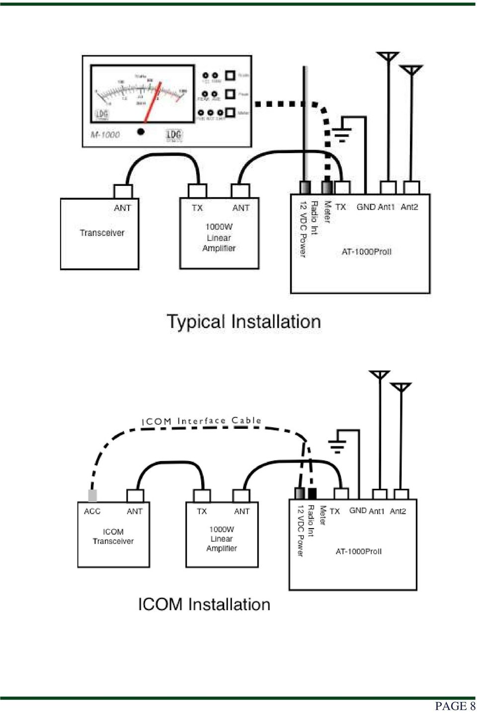
7 INSTALLATION The AT-1000ProII is intended for indoor use only; it is not water-resistant. If you use it outdoors, (Field Day, for example) you must protect it from rain. The AT-1000ProII is designed for use with coax-fed antennas. If use with longwires or ladder-line-fed antennas is desired, an external balun rated to 1000 watts is required. Place the AT-1000ProII in a convenient location near the transceiver and amplifier. Always turn your radio and amplifier off before plugging or unplugging anything. The radio may be damaged if cables are connected or disconnected while the power is on. Connect the HF antenna jack on the amplifier to the TX jack on the back of the AT- 1000ProII, using a 50 ohm coax cable rated 1000 watts or higher. Connect a 50-ohm antenna feedline coax to the ANT 1 jack on the back of the AT- 1000ProII, and optionally connect a second antenna feedline to the ANT 2 jack. NOTE: ANT 2 is automatically selected when no DC power is present. This way, if you only have one antenna connected to ANT 1, it is automatically disconnected from your radio when the power is off. The AT-1000ProII is designed to interface directly with many popular ICOM and Yaesu transceivers, enabling one button tuning. In the case of ICOM radios, the optional interface cable also powers the tuner. For ICOM radios supporting the AH-3 or AH-4 external tuner, connect the 4-pin Molex connector of the optional IC-PAC ICOM interface cable to the radio s Tuner port. Then connect the 1/8 stereo plug on the other end of the ICOM interface cable to the jack marked Radio on the rear of the AT-1000ProII. Connect the coaxial DC power plug of the ICOM interface cable to the 12V DC Power jack. For Yaesu FT-857 and FT-897, use the optional Y-ACC cable and plug the red end marked Radio into the transceiver s ACC port. Plug the black end of the Y-ACC cable into the jack marked Radio on the rear of the AT-1000ProII. Unless the AT-1000ProII is being powered by the ICOM radio interface cable as above, you ll also need to plug in the supplied DC coaxial power cable. This cable has a 2.5x5.5mm coaxial plug on the end. Plug the coaxial plug into the 12V DC Power jack on the rear of the AT-1000ProII, and connect the other end to a DC power source between 11 and 16 volts DC, capable of supplying up to 1A. Grounding the AT-1000ProII tuner will enhance its performance and safety. LDG recommends that you connect your tuner to a suitable ground. A common ground rod connected to buried radials is ideal, but a single ground rod can provide a serviceable ground. LDG strongly recommends the use of a properly installed, high quality lightning arrestor on all antenna cables. PAGE 7

8 PAGE 8
9 Note: Optional Y-ACC cable has a red plug on the radio end of the cable, and a black plug on the tuner end. PAGE 9

10 BASIC OPERATION Using the Front Panel Buttons All operations of the AT-1000ProII are controlled via the front panel buttons. Although there are a total of eight buttons on the front panel, there are more than eight functions that can be carried out on the AT-1000ProII. In order to accommodate the many functions of the AT- 1000ProII, the operation performed by pressing a particular button is determined by the manner in which the button is pressed, and no operation begins until the button is actually released. The various types of button presses are described here: Momentary or short press: The button is pressed and released immediately. Medium Press: The button is held for one-half to 2.5 seconds, and then released. Long Press: The button is held for more than 2.5 seconds, and then is released. FUNC -> Button: The FUNC button is pressed first, then the button is pressed momentarily and released. e.g.: FUNC -> Ant means Press the Func button and release, then press the Ant button and release. User Configuration Options The AT-1000ProII offers several user-settable options that allow the behavior of the tuner to adapt to many different operating circumstances. Most of these options are accessed by placing the tuner in Function mode, which is done by pressing and releasing the Func button, and then pressing the desired button to activate the particular configuration option while in function mode. To confirm entry into Function mode, the AT-1000ProII will flash an up arrow on the LED display after the Func button is pressed. PAGE 10

11 Function mode times-out after a few seconds if no other button is pushed. Alternately, function mode can be cancelled by pressing the Func button again. In either case, when Function mode is exited, a down arrow is displayed on the LED display: Peak Mode On/Off: The Power display on the LED bargraph can display either average power or peak forward power, in watts. Average mode is suitable for 100% duty cycle modes such as FM, RTTY, or PSK. Peak mode is more useful on modes with varying duty cycle such as SSB or AM. The factory default is average mode. To toggle between power display modes, press Func -> C Up (Press and release Func, then press and release C Up). Peak mode is indicated by a falling meter display, with the highest power shown as a steady LED while the remaining LEDs fall back to zero. Average mode shows the same display, but without the steady LED showing. Press Func -> C Up repeatedly to toggle between Peak and Average modes. PAGE 11
.")
12 Wattmeter Scale: The Power LED bargraph displays either 0 to 100 watts or 0 to 1000 watts full scale. To toggle between these two scales, press Func -> L Up. The LED marked 100 or 1000 will light momentarily to indicate the newly selected scale. Automatic Tuning Mode: The AT-1000ProII may be set for either semi-automatic tuning or fully automatic tuning. In semi-automatic tuning mode, a tuning cycle will not begin unless specifically requested by pressing the Tune button. In fully automatic tuning mode, a tuning cycle will begin any time there is RF present and the SWR exceeds a pre-set level. The default setting is fully automatic tuning mode. To toggle between semi- and fully automatic modes, press Func -> C Dn. The LED display will show one of the two patterns to indicate which mode has been selected: Automatic Tune SWR Threshold: When the AT-1000ProII is in fully automatic tuning mode, an automatic tuning cycle will begin any time RF is present and the SWR has exceeded a set threshold. This threshold is user-programmable to any value between 1.7:1 and 3.0:1. To set the automatic tune SWR threshold, press Func -> L Dn repeatedly (press Func, then L Dn; Func, then L Dn, and so on...) to cycle through all the options. The SWR threshold will be displayed on the SWR scale momentarily. PAGE 12

13 The default value of SWR threshold is 2.0:1. The following example shows setting the SWR threshold to 1.7:1. Antenna Selection: Press the Ant button momentarily to toggle which antenna port is currently active. The ANT 2 LED will light when Antenna 2 is selected, and is off when Antenna 1 is selected. When toggling the antenna selection, the previous tuning settings for the newly selected antenna are also recalled. This is useful when comparing antenna performance on the same frequency. Transmitting and Receiving During receive operation, only the antenna and bypass indicator LEDs are lit on the AT- 1000ProII. During transmit, the forward RF power level is displayed on the PWR bargraph, and the SWR is displayed on the SWR bargraph. When reading the SWR bargraph, an illuminated LED on the graph means The SWR is at least this much. In other words, if the 1.3 LED is lit, it means that the SWR is between 1.3 and 1.5:1. No LEDs lit means the SWR is less than 1.1:1. The Bypass LED lights any time that all the internal relays are in their de-energized state, meaning that no inductance or capacitance is being added to the antenna system by the tuner. PAGE 13

14 TUNING Basic Tuning Operation A tuning cycle on the AT-1000ProII is initiated from either the Tune button on the front of the AT-1000ProII, an over-swr condition when in fully automatic tuning mode, or from pressing the TUNER/CALL button on the front of an ICOM radio connected using the ICOM interface cable. Two types of tuning cycles are available. A memory tuning cycle attempts to tune quickly, based on having previously tuned on the present frequency selection. If the tuner previously was successful in tuning on the currently selected frequency, the settings from that match will be loaded into the tuner relays, and checked to see if an acceptable SWR level is found using these memorized settings. Memory frequency step sizes vary with the selected band. Steps are very close together on the lower bands, to accommodate the typically higher-q antennas for those bands, while step size is somewhat larger on the higher (17 meters and up) bands, where antenna Q is typically lower. A full tuning cycle starts from scratch, and begins a fixed tuning sequence, where the AT- 1000ProII rapidly tries varying combinations of inductance and capacitance values, and then zeroes-in on the best match possible. When the tuning cycle is complete, if an acceptable match was found, the inductance and capacitance settings are saved in a memory associated with the selected frequency and antenna, so that they may be recalled quickly in the future via a memory tuning cycle. In this manner, the AT-1000ProII learns; the longer you use it, the more closely it adapts itself to the bands and frequencies you use. Most users will probably use memory tuning most of the time; it takes advantage of any saved tuning settings, but automatically defaults to a full tuning cycle if no stored data is available. Manual Memory Tune To initiate a memory tuning cycle at any time, first, bypass the amplifier 2. Press and hold the Tune button for 0.5 to 2.5 seconds (medium button press) and release. The LED bargraph display will show the following pattern to indicate a memory tune cycle is selected: 2 Note that, while the AT-1000ProII employs software that prevents it from tuning while transmitting over 150 watts, it is still a good idea to bypass your amplifier while tuning, as further protection against damage to the tuner. PAGE 14

15 If you are using the optional ICOM or Yaesu interface cable, your radio will automatically reduce power, switch to CW mode, and transmit for as long as is needed to complete the tuning cycle, and then will return to the previous operating mode and power level when done. If you are not using the optional ICOM or Yaesu radio interface cable, you will need to key the radio manually in AM, SSB, or CW mode. Note that if your radio does not incorporate an SWR rollback circuit 3, you will first need to reduce power to 25 watts or less. In no case should you transmit more than 150 watts during tuning. If the memory tune is not successful, the AT-1000ProII defaults to the full tuning cycle. At the end of a tuning cycle, the LEDs cycle inwards to indicate a successful tune. You may then activate the amplifier, and begin transmitting. If using the AT-1000ProII with an ICOM transceiver connected with the ICOM interface cable, pressing the TUNER/CALL button on the transceiver initiates a memory tuning cycle. Again, bypass the amplifier while tuning. The AT-1000ProII will not tune if the transmit power is over 150 watts, or if the transmit power exceeds 100 watts during high SWR conditions, in order to protect the switching relays. Manual Full Tune As with the memory tuning cycle, if your radio is not equipped with a rollback circuit, reduce power to 25 watts or less before tuning. To explicitly initiate a full tuning cycle, press and hold the Tune button on the AT-1000ProII front panel for more than 2.5 seconds. The LEDs will display the following pattern to confirm a full tuning cycle is requested: If you are using one of the optional radio interface cables, the radio will automatically reduce power, switch to CW mode, and begin transmitting while the full tuning cycle is in progress. If not, key the radio (Talk into the mic on SSB or AM, close the key on CW) until the tuning cycle is complete. As with the memory tuning cycle, when the tuning cycle is complete, the LEDs will scan inward to indicate a successful tune. 3 An SWR rollback circuit automatically reduces the output power level when high SWR is present. Check your radio s manual to see if your radio uses a rollback circuit. PAGE 15

16 Bypass Mode The AT-1000ProII may be placed in bypass mode by pressing the Tune button momentarily (less than 0.5 second). Bypass places the tuner in a pass-thru configuration, where the tuner behaves like a coax jumper, not affecting the antenna match. When placed in Bypass mode, the AT-1000ProII is also put into semi-auto tuning mode. The tuner will remain in Semi-Auto Mode until you turn Auto Mode on again. Bypass may be useful for comparing the effect of the AT-1000ProII s tuning versus the unmatched antenna system. Pressing Tune momentarily again will return the tuner to active mode, and the relay settings of the previous match will be restored. When in bypass, the Bypass LED is lit. If an ICOM radio and interface cable is used, the AT-1000ProII may also be bypassed by pressing the TUNER/CALL button momentarily. On some models of ICOM radios, changing bands will also automatically bypass the tuner. When the tuner is placed in Bypass mode, it will remain in bypass mode until either: a.) You re-enable Full Auto mode. b.) You manually increment or decrement the inductor / capacitor settings. Error Indication When performing a tuning cycle, there are several conditions that may occur that cause the tune to fail. All are reported as an error, via blinking the front panel LEDs in a particular fashion. The following errors are reported: ERR_NO_MATCH: Unable to find a suitable match. Upon completing an entire full tuning cycle, no combination of inductors and capacitors was able to bring the SWR below 3.5:1. ERR_NO_RF: No RF power was present at the beginning of a tuning cycle. In other words, the Tune button was pressed to request a tune cycle, but the transmitter was not keyed up. ERR_LOST_RF: RF power disappeared before the tuning cycle completed. You must continue to key the radio until the tuning cycle completes. ERR_NO_FREQ: Unable to determine operating frequency. In order to store a memory match, the frequency of the transmitted RF must be known. ERR_OVER_PWR / ERR_SWR_PWR: Relay protection activated. Because the relays may be damaged if they are switching during high power operation, software prevents the relays from toggling under certain conditions. Relays will not toggle if the SWR is over 3.0:1 and the power is over 100 watts, and will not toggle if the power is over 150 watts regardless of the SWR. The diagrams on the next page show what the various error indications look like. PAGE 16

17 Additionally, if the forward power exceeds the maximum value selected for the meter scale, the PWR LEDs will blink an over-range condition. The four right-most LEDs of the PWR bargraph will cycle during over-range. PAGE 17

18 ADVANCED OPERATION Manual Inductor/Capacitor Adjustments In some rare cases, after tuning, it may be desirable to adjust the inductance and capacitance settings that the AT-1000ProII came up with during the tuning process. This is more likely to occur when attempting to tune an antenna far from its resonant frequency. The C Up, C Dn, L Up, and L Dn buttons may be used to increase or decrease the amount of capacitance or inductance, respectively. A momentary press of any of these buttons increases or decreases the value by one unit, and displays the resulting value on the bargraph meter. Capacitance value is displayed on the PWR bargraph, and inductance on the SWR bargraph. These values are displayed in binary, left justified. The lowest-order relay is displayed on the leftmost LED. The rightmost LED on the PWR bargraph displays the state of the High/Low Impedance relay. Repeatedly press one of these buttons to increase or decrease multiple times, or simply hold the button and the button will auto-repeat. You may also transmit while increasing or decreasing, so that the SWR value is displayed, but the capacitor and inductor values will not be displayed during transmit; instead, the power and SWR levels are displayed. High/Low Relay Adjustment In addition to being able to manually control the inductor and capacitor value of the AT- 1000ProII, it is also possible to manually set the high/low impedance relay, which determines whether the tuner is an L-C configuration or a C-L configuration. To toggle the state of the high/low impedance relay, press Func -> Ant. The LED bargraph will display one of two patterns to confirm the setting. Manual Memory Store Once manual adjustments are complete, press Func -> Tune (that is, press Func momentarily, then Tune momentarily) to store the current relay settings in the memory associated with the frequency last transmitted upon. PAGE 18

19 Status Check The status of most user settings can be checked by pushing and holding the Func button while pressing the relevant button for that setting. For example, to check to see what the current SWR threshold value is, without changing the value, press and hold the Func button, and while still holding the Func button, press the L Dn (Thresh) button. The display will show the currently selected SWR threshold value. While holding the Func button, the bargraph display will show the following pattern, to indicate that the AT-1000ProII is waiting for you to push a button to check its status: The following status items can be checked: Func Hold + This button C Up / Peak Status check Display Peak/Avg setting C Dn / Auto Display Auto/Semi setting L Up / Scale Display Power meter scale L Dn / Thresh Display SWR tuning threshold ANT / HiLoZ Display High / Low Impedance PAGE 19

20 APPLICATION NOTES Mobile Operation The AT-1000ProII is perfectly suited to mobile operation. It can be installed under the dashboard along with the transceiver, or mounted remotely. The only requirements are that the tuner remains dry, and that the power source is fused appropriately. A 2 amp fast blow fuse is recommended. If the ICOM or Yaesu radio interface cable is needed for a remote installation, the optional cables can be extended in two ways. The original cable can be cut, and jumper wires soldered between all the connections, or new connectors can be purchased and a pair of homebrew extender cables made with the new connectors. With the AT-1000ProII mounted, for example, in the trunk, simply set the AT-1000ProII for fully automatic mode. It will automatically tune any time the SWR exceeds the preprogrammed threshold. Although the LED display will not be visible in the trunk of the car, your transceiver s built-in SWR meter will show the tuner s progress. Remember to keep your eyes on the road, however! In most cases, a match will be recalled from memory, so the SWR will snap to a low value as soon as you begin to transmit. Internally Generated RF Noise The AT-1000ProII is microprocessor controlled, and as such, generates a small amount of RF noise when the processor is active. Normally, the processor is only active during transmit operation, so the noise is not normally heard; however, if Peak mode is selected, the processor remains active for a moment after key-up, to allow the LEDs to settle back down to zero. You may briefly hear some noise in your receiver during this time. This is normal, and is noticeable the most when using CW in full break-in, with Peak mode selected. In practice, this should not be much of a problem, as Peak mode is not very useful when using CW. MARS/CAP Coverage The AT-1000ProII provides continuous tuning coverage from 1.8 MHz to 54.0 MHz, not just inside the ham bands. This makes it useful for MARS or CAP operation, or any other legal HF operation. PAGE 20

21 Operation with LDG Electronics M-1000 External Meter The AT-1000ProII has an external meter jack on the rear panel, which supports use of the M External Meter. The M-1000 External Meter is an optional accessory for the AT-1000ProII that provides a large analog meter movement, and can be used to display Forward Power, Reflected Power, and SWR. Be sure to turn off your AT-1000ProII before plugging in or unplugging the M-1000 External Meter. The metered parameter displayed on the external meter need not be the same as the parameter selected for viewing on the AT-1000ProII s built-in LED bargraphs, so it is possible to watch two parameters at once! Consult the M-1000 External Meter user manual for more details. Tuning Hints 1.) The AT-1000ProII is designed to allow fully automatic tuning, which causes a tuning cycle to begin any time the SWR exceeds the user-selected threshold. However, tuning is not allowed when the forward power exceeds a level that could damage the relays. If the AT- 1000ProII is left in fully automatic mode with the amplifier active, it is possible to begin a tuning cycle while transmitting high power in some circumstances, such as SSB transmission, where the power level begins at a low level and then increases with voice peaks. Once the power level exceeds the relay protection threshold, the tuning cycle will stop, leaving the tuner in an un-tuned state. Because of this, LDG recommends switching the amplifier off before tuning, and then once tuning is complete, the AT-1000ProII should be switched to semi-automatic mode (FUNC -> Auto) for as long as the amplifier is active, to prevent re-tuning under high power. 2.) Some transceivers employ a fairly aggressive SWR roll-back circuit, which reduces transmit power under high SWR conditions. It is possible, on a particularly mismatched antenna, for the transmit power of the transceiver to be reduced so low that the frequency counter circuitry of the AT-1000ProII does not provide accurate information. For this reason, LDG suggests that you tune with 20 to 50 watts of transmit power if tuning seems erratic when transmitting with lower power levels. For many transceivers, this is a simple matter of switching the radio to AM or RTTY mode and keying the mic. THEORY OF OPERATION Some basic ideas about impedance The theory underlying antennas and transmission lines is fairly complex, and in fact employs a mathematical notation called complex numbers that have real and imaginary parts. It is beyond the scope of this manual to present a tutorial on this subject 4, but a little background will help in understanding what the AT-1000ProII is doing, and how it does it. In simple DC circuits, the wire resists current flow, converting some of it into heat. The relationship between voltage, current, and resistance is described by the elegant and well-known 4 For a very complete treatment of this subject, see any edition of the ARRL Handbook for Radio Communications (previously the Handbook For Radio Amateurs). PAGE 21
22 Ohm s Law, named for Georg Simon Ohm of Germany, who first discovered the principle in In RF circuits, an analogous but more complicated relationship exists. RF circuits also resist the flow of electricity. However, the presence of capacitive and inductive elements causes the voltage to lead or lag the current, respectively. In RF circuits, this resistance to the flow of electricity is called impedance, and can include all three elements: resistive, capacitive, and inductive. The output circuit of a transmitter consists of inductors and capacitors, usually in a series/parallel configuration called a pi network. The transmission line can be thought of as a long string of capacitors and inductors in series/parallel, and the antenna is a kind of resonant circuit. At any given RF frequency, each of these can exhibit resistance, and impedance in the form of capacitive or inductive reactance. Transmitters, transmission lines, antennas, and impedance The output circuit of a transmitter, the transmission line, and the antenna, each have a characteristic impedance. For reasons beyond the scope of this document, the standard impedance is nominally 50 ohms resistive, with zero capacitive and zero inductive components. When all three parts of the system have the same impedance, the system is said to be matched, and maximum transfer of power from the transmitter to the antenna occurs. While the transmitter output circuit and transmission line are of fixed, carefully designed impedance, the antenna presents 50-ohm, non-reactive load only at its natural resonant frequencies. At other frequencies, it will exhibit capacitive or inductive reactance, causing it to have an impedance other than 50 ohms. When the impedance of the antenna is different from that of the transmitter and transmission line, a mismatch is said to exist. In this case, some of the RF energy from the transmitter is reflected from the antenna back down the transmission line and into the transmitter. If this reflected energy is strong enough, it can damage the transmitter s output circuits. The ratio of transmitted to reflected energy is called the standing wave ratio, or SWR. An SWR of 1 (sometimes written 1:1) indicates a perfect match. As more energy is reflected, the SWR increases to 2, 3, or higher. As a general rule, modern solid state transmitters must operate with an SWR of 2 or less. Tube exciters are somewhat more tolerant of high SWR. If a 50 ohm antenna is resonant at the operating frequency, it will show an SWR close to 1. However, this is usually not the case; operators often need to transmit at frequencies other than resonance, resulting in a reactive antenna and a higher SWR. PAGE 22
23 SWR = 1+ 1 R F R F where F = Forward power (watts), R = Reflected power (watts) SWR is measured using a device called an SWR bridge, inserted in the transmission line between the transmitter and the antenna. This circuit measures forward and reflected power from which SWR may be calculated (some meters calculate SWR for you). More advanced units can measure forward and reflected power simultaneously, and show these values and SWR at the same time. An antenna tuner is a device used to cancel out the effects of antenna reactance. Tuners add capacitance to cancel out inductive reactance in the antenna, and vice versa. Simple tuners use variable capacitors and inductors; the operator adjusts them by hand while observing reflected power on the SWR meter until a minimum SWR is reached. The LDG Electronics AT-1000ProII automates this process. No tuner will fix a bad antenna. If the antenna is far from resonance, the inefficiencies inherent in such operation are inescapable; it s simple physics. Much of the transmitted power may be dissipated in the tuner as heat, never reaching the antenna at all. A tuner simply fools the transmitter into behaving as though the antenna were resonant, avoiding any damage that might otherwise be caused by high reflected power. For best performance, the antenna used should always be as close to resonance as is practical. PAGE 23
24 THE LDG AT-1000PROII In 1995, LDG Electronics pioneered a new type of automatic antenna tuner. The LDG design uses banks of fixed capacitors and inductors, switched in and out of the circuit by relays under microprocessor control. An additional relay switches between high and low impedance ranges. A built-in SWR sensor provides feedback; the microprocessor searches the capacitor and inductor banks, seeking the lowest possible SWR. The tuner is a Switched L network, consisting of series inductors and parallel capacitors. LDG chose the L network for its minimum number of parts and its ability to tune unbalanced loads, such as coax-fed dipoles, verticals, Yagis, and, in fact, virtually any coax-fed antenna. The series inductors are switched in and out of the circuit, and the parallel capacitors are switched to ground under microprocessor control. The high/low impedance relay switches the capacitor bank either to the transmitter side of the inductor bank, or to the antenna side. This allows the AT-1000ProII to handle loads that are either greater than or less than 50 ohms. All relays are sized to carry 1000 watts continuously. The relays are non-latching, so power is required to hold the current match. The SWR sensor is a variation of the Bruene circuit. This SWR measuring technique is used in most dual-meter and direct-reading SWR meters. Slight modifications were made to the circuit to provide voltages instead of currents for the analog-to-digital converters that provide signals proportional to the forward and reflected power levels. The single-lead primary through the center of the sensor transformer provides RF current sampling. Diodes rectify the sample and provide a DC voltage proportional to RF power. These two voltages are read by the ADCs in the microprocessor, and are used to compute SWR in real time. Although the microprocessor s oscillator runs at 32 MHz, which allows the main tuning routine to execute in only a few milliseconds, the relays require several milliseconds of settling time for every combination of inductors and capacitors. Thus, it may take several seconds before all relay combinations are exhausted, in the case of a difficult tune. The tuning routine uses an algorithm to minimize the number of tuner adjustments. The routine first de-energizes the high/low impedance relay if necessary, and then individually steps through the inductors to find a coarse match. With the best inductor selected, the tuner then steps through the individual capacitors to find the best coarse match. If no match is found, the routine repeats the coarse tuning with the high/low impedance relay energized. The routine then fine tunes the inductors and capacitors. The program checks LC combinations to see if a 1.5:1 or lower SWR can be obtained and stops when it finds a good match. The microprocessor runs a fine tune routine just after the tuner finds a match of 1.5:1 or less. This fine tune routine now tries to make the SWR as low as possible (not just to 1.5); it takes about half a second to run. PAGE 24
25 A WORD ABOUT TUNING ETIQUETTE Be sure to use a vacant frequency when tuning. With today s crowded ham bands, this is often difficult. However, causing interference to other hams should be avoided as much as possible. The AT-1000ProII s very short tuning cycle, as little as a fraction of a second, minimizes the impact of tuning transmissions. CARE AND MAINTENANCE The AT-1000ProII tuner is essentially maintenance-free. Power limits in this manual should be strictly adhered to. The outer case may be cleaned as needed with a soft cloth slightly dampened with household cleaning solution. As with any modern electronic device, the AT- 1000ProII can be damaged by temperature extremes, water, impact, or static discharge. LDG strongly recommends the use of a good quality, properly installed lightning arrestor in the antenna lead. PAGE 25
26 QUICK REFERENCE Button Primary Function Func -> Button Status Check (Func Hold + Button) Full Tune (Long Press) Tune Memory Tune (Medium Press) Bypass (Short Press) Manually Store Tuning Parameters Display Relay Settings Ant Toggle Antenna Selection Toggle High/Low Impedance Display High/Low Impedance C Up Increase Capacitance Toggle Peak / Average Power Display PWR Meter Mode C Dn Decrease Capacitance Toggle Auto / Semi Mode Display Auto / Semi Selection L Up Increase Inductance Set PWR Meter Scale Display PWR Meter Scale L Dn Decrease Inductance Set Auto Tuning SWR Threshold Display Auto Tuning SWR Threshold Func Select Secondary Button Functions PAGE 26
27 TECHNICAL SUPPORT The LDG customer support staff is ready to answer your product question by telephone and by . We know that you will enjoy your product even more knowing LDG is ready to answer your questions as the need arises. LDG regularly updates on-line information so the best on-line support information is available all day and every day. The LDG website provides links to product manuals, just in case you lose this one! When you are thinking about the purchase of other LDG products our website also has complete product specifications and photographs you can use to help make your purchase decision. Don t forget the links to all of the quality LDG Dealers also ready to help you make that purchase decision. TWO-YEAR TRANSFERRABLE WARRANTY Your product is warranted against manufacturer defects in parts and labor for two full years from the date of purchase. This two-year warranty is also transferable. When you sell or give away your LDG product, give the new owner a copy of the original sales receipt and the twoyear warranty goes with the new owner. There is no need to complete a warranty card or to register an LDG product. Your product receipt establishes eligibility for warranty service, so save that receipt. Send your receipt with the product whenever you send your product to LDG for repair. Products sent to LDG without a receipt are considered requests for out-of-warranty repair. LDG does not warranty against product damage or abuse. This means that a product failure, as determined by LDG, to be caused by the customer or by other natural calamity (e.g. lightning) is not covered under the two-year warranty. Damage can be caused by failure to heed the product s published limitations and specifications or by not following good Amateur practice. OUT OF WARRANTY SERVICE If a product fails after the warranty period, LDG wants to help you get it fixed. Send the product to us for repair any time you like. We will determine what needs to be done and based on your instructions, either contact you with an estimate or fix it and contact you with a request to pay any repair charges. RETURNING YOUR PRODUCT FOR SERVICE Returning a product to LDG is easy. We do not require a return merchandise authorization, and there is no need to contact LDG to return your product. Visit the LDG web site and download the LDG Product Repair Form. On the Repair Form tell the LDG technicians exactly what happened or didn t happen and why you believe the product needs servicing. The technician attempts to duplicate the problem(s) you had based on how well you describe it so take the time to be accurate and complete. Ask your shipper for a tracking number or a delivery verification receipt. This way you know the product arrived safely at LDG. Be sure to give us your address so our shipper can alert PAGE 27

28 you online when your product is en-route back to you. Please be assured that our staff makes every effort to complete repairs ahead of our published wait time. Your patience is appreciated. Repairs can take six to eight weeks, but are usually faster. The most recent information on returning products for service is found on the LDG website under Support, then Tech Support. Send your carefully packaged unit with the Repair Form to: LDG Electronics, Inc. Attn: Repair Department 1445 Parran Rd St. Leonard, MD PRODUCT FEEDBACK We encourage product feedback! Tell us what you really think of your LDG product. In a card, letter, or (preferred) tell us how you used the product and how well it worked in your application. Send along a photo or even a schematic or drawing to illustrate your narrative. We like to share your comments with our staff, our dealers, and even other customers at the LDG website: PAGE 28
LDG AT-200ProII 200W Automatic Antenna Tuner
 AT-200PROII OPERATIONS MANUAL MANUAL REV B LDG AT-200ProII 200W Automatic Antenna Tuner LDG Electronics 1445 Parran Road St. Leonard MD 20685-2903 USA Phone: 410-586-2177 Fax: 410-586-8475 [email protected]
LDG IT-100 100-Watt Automatic Tuner for Icom Transceivers
 IT-100 OPERATIONS MANUAL MANUAL REV A LDG IT-100 100-Watt Automatic Tuner for Icom Transceivers LDG Electronics 1445 Parran Road St. Leonard MD 20685-2903 USA Phone: 410-586-2177 Fax: 410-586-8475 [email protected]
LDG Z-100Plus 100-Watt Automatic Tuner
 Z-100PLUS OPERATIONS MANUAL MANUAL REV A LDG Z-100Plus 100-Watt Automatic Tuner LDG Electronics 1445 Parran Road St. Leonard MD 20685-2903 USA Phone: 410-586-2177 Fax: 410-586-8475 [email protected]
LDG M-7700 External Meter for Icom IC-7700
 M-7700 OPERATIONS MANUAL MANUAL REV A LDG M-7700 External Meter for Icom IC-7700 LDG Electronics 1445 Parran Road St. Leonard MD 20685 Phone: 410-586-2177 Fax: 410-586-8475 [email protected] www.ldgelectronics.com
LDG SLS-2 Two-Port RJ45 Switch
 SLS-2 OPERATIONS MANUAL MANUAL REV. A LDG SLS-2 Two-Port RJ45 Switch LDG Electronics 1445 Parran Road St. Leonard MD 20685-2903 USA Phone: 410-586-2177 Fax: 410-586-8475 [email protected] www.ldgelectronics.com
LDG DTS-6/6R Desktop Coaxial Switch / Remote
 LDG DTS-6/6R Desktop Coaxial Switch / Remote LDG Electronics 1445 Parran Road, PO Box 48 St. Leonard MD 20685-2903 USA Phone: 410-586-2177 Fax: 410-586-8475 [email protected] www.ldgelectronics.com
LDG YT-847 100-Watt Automatic Tuner for Yaesu FT-847 Transceivers
 YT-847 OPERATIONS MANUAL MANUAL REV A LDG YT-847 100-Watt Automatic Tuner for Yaesu FT-847 Transceivers LDG Electronics 1445 Parran Road St. Leonard MD 20685-2903 USA Phone: 410-586-2177 Fax: 410-586-8475
Z-100 Automatic Antenna Tuner Manual Version 1.1
 Z-100 Automatic Antenna Tuner Manual Version 1.1 LDG Electronics 1445 Parran Road, PO Box 48 St. Leonard MD 20685-2903 USA Phone: 410-586-2177 Fax: 410-586-8475 [email protected] www.ldgelectronics.com
LDG Z-817 20-Watt Automatic Tuner with FT-817 Integration
 Z-817 OPERATIONS MANUAL MANUAL REV A LDG Z-817 20-Watt Automatic Tuner with FT-817 Integration LDG Electronics 1445 Parran Road St. Leonard MD 20685-2903 USA Phone: 410-586-2177 Fax: 410-586-8475 [email protected]
LDG DTS-4/4R Desktop Coaxial Switch / Remote
 LDG DTS-4/4R Desktop Coaxial Switch / Remote LDG Electronics 1445 Parran Road, PO Box 48 St. Leonard MD 20685-2903 USA Phone: 410-586-2177 Fax: 410-586-8475 [email protected] www.ldgelectronics.com
AT-897Plus Automatic Tuner for Yaesu FT-897(D)
") AT-897PLUS OPERATIONS MANUAL MANUAL REV B AT-897Plus Automatic Tuner for Yaesu FT-897(D) LDG Electronics 1445 Parran Road St. Leonard MD 20685-2903 USA Phone: 410-586-2177 Fax: 410-586-8475 [email protected]
AT-897PLUS OPERATIONS MANUAL MANUAL REV B AT-897Plus Automatic Tuner for Yaesu FT-897(D) LDG Electronics 1445 Parran Road St. Leonard MD 20685-2903 USA Phone: 410-586-2177 Fax: 410-586-8475 [email protected]
LDG Z-817H 75-Watt Automatic Tuner
 Z-817H OPERATIONS MANUAL MANUAL REV A LDG Z-817H 75-Watt Automatic Tuner for Yaesu FT-817 and Other QRP Radios with Amplifiers LDG Electronics 1445 Parran Road St. Leonard MD 20685-2903 USA Phone: 410-586-2177
LDG YT-450 100-Watt Automatic Tuner for Yaesu FT-450 and FT-950 Transceivers
 YT-450 OPERATIONS MANUAL MANUAL REV A LDG YT-450 100-Watt Automatic Tuner for Yaesu FT-450 and FT-950 Transceivers LDG Electronics 1445 Parran Road St. Leonard MD 20685-2903 USA Phone: 410-586-2177 Fax:
LDG Electronics External Meter Serial Communications Protocol Specification
 M1000 METER PROTOCOL SPECIFICATION MANUAL REV A LDG Electronics External Meter Serial Communications Protocol Specification LDG Electronics 1445 Parran Road St. Leonard MD 20685-2903 USA Phone: 410-586-2177
Z-11Pro Automatic Antenna Tuner Manual Version 1.1
 Z-11Pro Automatic Antenna Tuner Manual Version 1.1 LDG Electronics 1445 Parran Road, PO Box 48 St. Leonard MD 20685-2903 USA Phone: 410-586-2177 Fax: 410-586-8475 [email protected] www.ldgelectronics.com
LDG RBA-4:1Balun LDG RBA-1:1Balun
 LDG RBA-4:1Balun LDG RBA-1:1Balun Table of Contents Features 1 Specifications 1 Preparation 2 An important word about power levels: 2 Installation 2 Care and Maintenance 6 Technical Support 6 Warranty
AT-200PC Automatic PC-Controlled Antenna Tuner Manual Version 1.1
 AT-200PC Automatic PC-Controlled Antenna Tuner Manual Version 1.1 LDG Electronics 1445 Parran Road, PO Box 48 St. Leonard MD 20685-2903 USA Phone: 410-586-2177 Fax: 410-586-8475 [email protected]
W8UM STATION EQUIPMENT DOCUMENTATION AMP-HF-SB-220. Date: 12/27/2006 Author: C. Galbraith KA8WFC Contact: (734) 678-2779
 678-2779") W8UM STATION EQUIPMENT DOCUMENTATION AMP-HF-SB-220 Equipment: Heathkit SB-220 HF Amplifier Scope: Description, Operation, History Date: 12/27/2006 Author: C. Galbraith KA8WFC Contact: [email protected],
W8UM STATION EQUIPMENT DOCUMENTATION AMP-HF-SB-220 Equipment: Heathkit SB-220 HF Amplifier Scope: Description, Operation, History Date: 12/27/2006 Author: C. Galbraith KA8WFC Contact: [email protected],
Modifying the Yaesu FT-847 External 22.625 MHz Reference Input
 Modifying the Yaesu FT-847 External 22.625 MHz Reference Input David Smith VK3HZ Introduction This document describes the modification of an FT-847 to allow an external 22.625 MHz Reference oscillator
Safety Warnings and Guidelines
 Safety Warnings and Guidelines Thank you for purchasing this Wireless Speaker Amplifier! For best results, please thoroughly read this manual and carefully follow the instructions. Please pay extra attention
Constructing a precision SWR meter and antenna analyzer. Mike Brink HNF, Design Technologist.
 Constructing a precision SWR meter and antenna analyzer. Mike Brink HNF, Design Technologist. Abstract. I have been asked to put together a detailed article on a SWR meter. In this article I will deal
Ameritron ATP-102 Tuning Pulser II
 Ameritron ATP-102 The Ameritron ATP-102 relieves temperature related stress on amplifiers, tuners, and dummy loads while allowing proper system adjustments. It allows amplifiers to be properly adjusted
Short Range Wireless Switch System Handheld 8 Installation and Operations Guide
 Phone: (866) 701-1146 Fax: (425) 216-7558 www.remotecontroltech.com Short Range Wireless Switch System Handheld 8 Installation and Operations Guide Introduction... 2 Before Installation... 2 Receiver Installation...
Alpha 10 SERVICE MANUAL. Downloaded from www.cbradio.nl. MAX 10 Meter Amateur Transceiver AM/FM/CW/SSB 6 BAND PROGRAMMABLE MODEL AM-1000.
 Alpha 10 MAX 10 Meter Amateur Transceiver MODEL AM-1000 AM/FM/CW/SSB 6 BAND PROGRAMMABLE SERVICE MANUAL Downloaded from www.cbradio.nl Cover Page LOUDER TALKBACK MOD Alpha 10 Max - Model AM-1000 4.7K Resistor
Germanium Diode AM Radio
 Germanium Diode AM Radio LAB 3 3.1 Introduction In this laboratory exercise you will build a germanium diode based AM (Medium Wave) radio. Earliest radios used simple diode detector circuits. The diodes
Just a Dipole. Gary Wescom N0GW July 16, 2007
 Just a Dipole Gary Wescom N0GW July 16, 2007 Often we will hear people describing their antennas as just a dipole. After all, a coax cable fed, half wavelength dipole is one of the simplest antennas to
Smarthome SELECT Bluetooth Wireless Stereo Audio Receiver and Amplifier INTRODUCTION
 Smarthome SELECT Bluetooth Wireless Stereo Audio Receiver and Amplifier INTRODUCTION The Smarthome SELECT Bluetooth Wireless Stereo Audio Receiver and Amplifier is a multi-functional compact device. It
MAINTENANCE & ADJUSTMENT
 MAINTENANCE & ADJUSTMENT Circuit Theory The concept of PLL system frequency synthesization is not of recent development, however, it has not been a long age since the digital theory has been couplet with
Stop Alert Flasher with G-Force sensor
 Stop Alert Flasher with G-Force sensor Stop Alert module creates brake light flashing effect to catch attention of the drivers behind to avoid dangerous rear end collision. The flasher module is a state
Operation Manual for Users
 Operation Manual for Users Model No.: FLTAMFMRCD!!!!!!!!!! ATTENTION!!!!!!!!!! THE RESET BUTTON MUST BE PRESSED TO ENSURE PROPER OPERATION. SEE INSTRUCTION MANUAL Table of Contents Table of Contents ---------------------------------------------------------------------------------------------
Quick start: Energy Switch EU
 Technical specifications Normal operating voltage Quick start: Energy Switch EU 230Vac/50Hz Recommended max. load 3000W 600W Frequency range Wireless range Energy measurement 868.42 MHz 30~100 meters in
THE KW107 SUPERMATCH ATU manual, courtesy of Barry G0DWZ
 THE KW107 SUPERMATCH ATU manual, courtesy of Barry G0DWZ I ve copied the following directly from the KW107 manual without alteration. To clear up one or two ambiguous points, I have added my own comments
AM / FM Tuner + RDS. Model: TU-101. www.pulse-audio.co.uk
 AM / FM Tuner + RDS Model: TU-101 www.pulse-audio.co.uk 1 Safety Information The lightning bolt within a triangle is intended to alert the user to the presence of dangerous voltage levels within the product
RigExpert AA-30 Antenna Analyzer (0.1 to 30 MHz) AA-54 Antenna Analyzer (0.1 to 54 MHz) User s manual
 AA-54 Antenna Analyzer (0.1 to 54 MHz) User s manual") RigExpert AA-30 Antenna Analyzer (0.1 to 30 MHz) AA-54 Antenna Analyzer (0.1 to 54 MHz) User s manual Table of contents 1. Description... 3 2. Specifications... 4 3. Precautions... 5 4. Operation... 6
RigExpert AA-30 Antenna Analyzer (0.1 to 30 MHz) AA-54 Antenna Analyzer (0.1 to 54 MHz) User s manual Table of contents 1. Description... 3 2. Specifications... 4 3. Precautions... 5 4. Operation... 6
MODEL 2202IQ (1991-MSRP $549.00)
") F O R T H E L O V E O F M U S I C F O R T H E L O V E O F M U S I C MODEL 2202IQ (1991-MSRP $549.00) OWNER'S MANUAL AND INSTALLATION GUIDE INTRODUCTION Congratulations on your decision to purchase a LINEAR
F O R T H E L O V E O F M U S I C F O R T H E L O V E O F M U S I C MODEL 2202IQ (1991-MSRP $549.00) OWNER'S MANUAL AND INSTALLATION GUIDE INTRODUCTION Congratulations on your decision to purchase a LINEAR
DX 2517. AM FM SSB CW PA Amateur Base Station Transceiver OWNER S MANUAL RX / TX 2 4 POWER NF CHANNEL MODE RF POWER OFF CAL OFF OFF CALIBRATE
 1 2 3 6 4050 ULA 6070 TI 80 90 100 9 DX 2517 2517 RX / TX 0 2 4 SWR WATTS SET 81012 22 1 010 3 2030 5 MOD 7 ON dbover 9 SIGNAL +20 +40+60 PA FM AM USB LSB CW POWER ON SWR NB / ANL R.BEEP +10KHz NF CHANNEL
ATS-505. GB Version 1
 ATS-505 GB Version 1 Control Locations Power/Sleep Power On/off/Alarm off/sleep function Display Switch between radio frequency and time while radio is power on Mode Mode set up (please see below mode
DAB1001. Wireless Digital Radio Interface. Installation & User Guide
 DAB1001 Wireless Digital Radio Interface Installation & User Guide Contents Contents... 2 Introduction... 3 Contents of Package... 4 Installation... 5 Product Overview... 5 Installation Procedure... 5
RLC Series Resonance
 RLC Series Resonance 11EM Object: The purpose of this laboratory activity is to study resonance in a resistor-inductor-capacitor (RLC) circuit by examining the current through the circuit as a function
Tiny Audio C3. English TINY AUDIO C3. Please read carefully before using this product
 English TINY AUDIO C3 Please read carefully before using this product 1 Safety Instructions: 1. Do not use this radio near water. 2. Clean with dry cloth. 3. Do not block any ventilation openings. 4. Do
Owner s Manual AWM910 JENSEN AWM910 COMPACT DISC PLAYER RADIO CD COMPACT MUSIC SYSTEM MUTE AUX BAND AUX IN PUSH PUSH PWR VOL ALARM T/F AUD SPK A SPK B
 AWM910 Owner s Manual COMPACT DISC PLAYER PUSH 1 2 3 4 5 6 RPT SCAN RDM H M PUSH PWR VOL ALARM SET ON/OFF EQ T/F AUD RADIO CD COMPACT MUSIC SYSTEM MUTE AUX BAND CD AUX IN A B A+B JENSEN AWM910 Thank You!
OPERATING INSTRUCTIONS Model ST-888 DTMF ANI/ENI Display Decoder
 P R O D U C T G R O U P OPERATING INSTRUCTIONS Model ST-888 DTMF ANI/ENI Display Decoder Manual # 600-0901 November 30, 1999 Rev. D - 99068 DESCRIPTION The ST-888 Mobilecall Display Decoder is a desktop
Operational Overview and Controls Guide
 DOCUMENT: ECSEQ2-1 EFFECTIVE: 02/14/07 SUPERSEDES: 02/26/03 Operational Overview and Controls Guide Standard Two or Three Pump Type VFD Booster Controls 6700 Best Friend Road. Norcross, GA 30071. (770)
DL-QRP-AG Lambda/2 no Counterpoise: Fuchs Antenna matching unit
 DL-QRP-AG Lambda/2 no Counterpoise: Fuchs Antenna matching unit QRPproject Molchstr. 15 12524 Berlin http://www.qrpproject.de Telefon: +49(30) 85 96 13 23 e-mail: [email protected] Handbucherstellung:
Homebuilt HF Radios for Use Underground Paul R. Jorgenson KE7HR
 Homebuilt HF Radios for Use Underground Paul R. Jorgenson KE7HR With the good success in using Amateur Band HF radio for underground communications, I started looking for cheaper alternatives to the $500+
MidiStream. UHF Wireless MIDI System Operating Manual
 MidiStream UHF Wireless MIDI System Operating Manual Introduction Congratulations on your purchase of the MidiStream UHF wireless MIDI system. The MidiStream system is very easy to use, but please take
IN-OUT Thermometer with Cable Free Sensor and Clock
 IN-OUT Thermometer with Cable Free Sensor and Clock MODEL: RAR232 USER'S MANUAL INTRODUCTION Congratulations on your purchase of the RAR232 In-Out Thermometer with 433MHz cable free sensor and calendar
Impedance Matching and Matching Networks. Valentin Todorow, December, 2009
 Impedance Matching and Matching Networks Valentin Todorow, December, 2009 RF for Plasma Processing - Definition of RF What is RF? The IEEE Standard Dictionary of Electrical and Electronics Terms defines
M&S SYSTEMS Model MC602 Master Unit. Owner's Guide
 M&S SYSTEMS Model MC602 Master Unit This booklet contains the information you need to get the most from your musical intercom system. It also tells you what to do if your system develops operating problems,
40 Watt Mixer Amplifier Owners Manual with Media Player
 40 Watt Mixer Amplifier with Media Player Model #USB-80 2009 MCM Electronics MCM Custom Audio MCM Electronics Centerville, Ohio www.mcmelectronics.com SAFETY INSTRUCTIONS Please be sure to read all the
SP1790JK 900MHz Wireless Indoor/Outdoor Speakers. User Manual INTRODUCTION FEATURES IMPORTANT SAFETY INFORMATION
 SP1790JK 900MHz Wireless Indoor/Outdoor Speakers INTRODUCTION This 900 MHz digital hybrid wireless speaker system uses the latest wireless technology that enables you to enjoy music and TV sound anywhere
The basic set up for your K2 to run PSK31 By Glenn Maclean WA7SPY
 The basic set up for your K2 to run PSK31 By Glenn Maclean WA7SPY I am by no means an expert on PSK31. This article is intended to help someone get on PSK31 with a K2. These are the things I did to get
TR7322U-OR RDS / MP3-USB TUNER (24 Volt)
") www.vdo.com TR7322U-OR RDS / MP3-USB TUNER (24 Volt) OWNER'S MANUAL Safety Information Safety Information Thank you for purchasing this product, please read the manual carefully before operating, and reserve
www.vdo.com TR7322U-OR RDS / MP3-USB TUNER (24 Volt) OWNER'S MANUAL Safety Information Safety Information Thank you for purchasing this product, please read the manual carefully before operating, and reserve
FILTERS - IN RADIO COMMUNICATIONS
 Reading 32 Ron Bertrand VK2DQ http://www.radioelectronicschool.com FILTERS - IN RADIO COMMUNICATIONS RADIO SIGNALS In radio communications we talk a lot about radio signals. A radio signal is a very broad
THE MclNTOSH MC 2100 SOLID STATE STEREO POWER AMPLIFIER
 THE MclNTOSH MC 2100 SOLID STATE STEREO POWER AMPLIFIER Price $1.25 Your MC 2100 stereo amplifier will give you many years of pleasant and satisfactory performance. If you have any questions concerning
OPTIMA MK2 OWNERS MANUAL & USER GUIDE. Downloaded from www.cbradio.nl. 24.500 29.999 Mhz 50W All Mode HF Mobile Transceiver
 OPTIMA MK2 OWNERS MANUAL & USER GUIDE Downloaded from www.cbradio.nl 24.500 29.999 Mhz 50W All Mode HF Mobile Transceiver (February 2012 production) REV 1.61 Copyright January 2012 by YeticomNZ. All rights
Mobile 3G. Cellular Signal Booster 460102. Need help? www.wilsonelectronics.com Tech Support 866-294-1660 Mon.- Fri. Hours: 7 am to 6 pm MST
 Mobile 3G Cellular Signal Booster 460102 Need help? www.wilsonelectronics.com Tech Support 866-294-1660 THE ALUMINUM CASING OF YOUR SIGNAL BOOSTER!! WILL ADJUST TO THE TEMPERATURE OF ITS ENVIRONMENT, BUT
Understanding SWR by Example
 Understanding SWR by Example Take the mystery and mystique out of standing wave ratio. Darrin Walraven, K5DVW It sometimes seems that one of the most mysterious creatures in the world of Amateur Radio
Congratulations on purchasing Molten MIDI B by Molten Voltage
 OWNER S MANUAL Congratulations on purchasing Molten MIDI B by Molten Voltage Molten MIDI B is designed to control the Digitech Bass Whammy. When configured for Whammy & Clock output, Molten MIDI B also
DR 70 Portable Digital DAB+ and FM Radio Receiver User Manual English Please read carefully before using this product
 DR 70 Portable Digital DAB+ and FM Radio Receiver User Manual Please read carefully before using this product 15 1 Table of Contents 1 Table of Contents... 16 2 Safety Instructions:... 17 3 Specification:...
PR-D9W. GB Version 1
 PR-D9W Version 1 Table of contents Important safety instructions... 2-3 Introduction... 4 Controls... 5-8 Using your weather alert radio for the first time... 9 Operating your radio Search tuning AM/FM...
User's Guide. Integrating Sound Level Datalogger. Model 407780. Introduction
 User's Guide 99 Washington Street Melrose, MA 02176 Phone 781-665-1400 Toll Free 1-800-517-8431 Visit us at www.testequipmentdepot.com Back to the Extech 407780 Product Page Integrating Sound Level Datalogger
PS 155 WIRELESS INTERCOM USER MANUAL
 PS 155 INTERFACE TO SIMPLEX WIRELESS INTERCOM USER MANUAL Issue 2011 ASL Intercom BV DESIGNED AND MANUFACTURED BY: ASL INTERCOM BV ZONNEBAAN 42 3542 EG UTRECHT THE NETHERLANDS PHONE: +31 (0)30 2411901
Technical Manual. FAN COIL CONTROLLER COOLING or HEATING ANALOG or PWM Art. 119914 631001A
 COOLING or HEATING ANALOG or PWM Art. 119914 631001A TOTAL AUTOMATION GENERAL TRADING CO. LLC SUITE NO.506, LE SOLARIUM OFFICE TOWER, SILICON OASIS, DUBAI. UAE. Tel. +971 4 392 6860, Fax. +971 4 392 6850
ITC-BTTN Cellular Bluetooth Gateway. Owner s Manual 1
 ITC-BTTN Cellular Bluetooth Gateway Owner s Manual 1 2 Table of Contents Introduction...3 Package Contents...3 XLink Connections Diagram...4 Setup...5 Pairing your Bluetooth Cell Phone to the XLink...6
GENERATOR START CONTROL MODULE - MINI (2 Wire to 3 Wire)
") FEATURES & APPLICATIONS Inexpensive 2 wire to 3 wire start controller for electric start high speed gas generators. Optimized for use with Outback Invertors. Supports three types of 3 wire generator control
FEATURES & APPLICATIONS Inexpensive 2 wire to 3 wire start controller for electric start high speed gas generators. Optimized for use with Outback Invertors. Supports three types of 3 wire generator control
SB-2000 USB Radio Interface Operating Manual CG Antenna Co. Ltd.
 CG Antenna SB-2000 USB Radio Interface Operating Manual CG Antenna Co. Ltd. Shanghai, China FEATURES Connect your computer with USB port. No need serial or parallel port. Most of Radio programs are built
Byonics Micro Trak 1000 High Altitude Balloon Tracker
 Byonics Micro Trak 1000 High Altitude Balloon Tracker The Micro Trak 1000 (MT 1000) is a high altitude balloon (HAB) tracker. It is usually sold as a combination to provide a simple, turn key tracking
Digital Active Indoor Antenna SRT ANT 10 ECO
 Digital Active Indoor Antenna SRT ANT 10 ECO Picture similar User Manual Table of contents 1.0 INTRODUCTION 1 2.0 PACKAGE CONTENT 1 3.0 SAFETY NOTES 2 4.0 CONNECTING THE ANTENNA 2 1.0 INTRODUCTION Thank
AutoRanging Digital MultiMeter
 Owner's Manual AutoRanging Digital MultiMeter Model No. 82139 CAUTION: Read, understand and follow Safety Rules and Operating Instructions in this manual before using this product. Safety Operation Maintenance
Guide. Installation. Signal Booster. Wilson. In-Building Wireless Smart Technology Signal Booster. Contents:
 Signal Booster Installation Guide In-Building Wireless Smart Technology Signal Booster Contents: Antenna Options and Accessories................... 1 Before Getting Started / How It Works...............
ECEN 1400, Introduction to Analog and Digital Electronics
 ECEN 1400, Introduction to Analog and Digital Electronics Lab 4: Power supply 1 INTRODUCTION This lab will span two lab periods. In this lab, you will create the power supply that transforms the AC wall
The Parts of the System
 2 The Parts of the System THE RECEIVER THE RECEIVER FRONT PANEL Power Light This green light on the receiver front panel lights up when the receiver is turned ON. This light flashes when the receiver memory
BASIC ELECTRONICS AC CIRCUIT ANALYSIS. December 2011
 AM 5-202 BASIC ELECTRONICS AC CIRCUIT ANALYSIS December 2011 DISTRIBUTION RESTRICTION: Approved for Pubic Release. Distribution is unlimited. DEPARTMENT OF THE ARMY MILITARY AUXILIARY RADIO SYSTEM FORT
CelluLine CGW-TS GSM Cellular Gateway. Installation and Programming Manual
 CelluLine CGW-TS GSM Cellular Gateway Installation and Programming Manual CelluLine CGW-TS GSM Cellular Gateway Installation and Programming Manual CGWTS-M001A Version 1, Release 1, December 2004 NOTICE
Experiment #11: LRC Circuit (Power Amplifier, Voltage Sensor)
") Experiment #11: LRC Circuit (Power Amplifier, Voltage Sensor) Concept: circuits Time: 30 m SW Interface: 750 Windows file: RLC.SWS EQUIPMENT NEEDED Science Workshop Interface Power Amplifier (2) Voltage
Experiment #11: LRC Circuit (Power Amplifier, Voltage Sensor) Concept: circuits Time: 30 m SW Interface: 750 Windows file: RLC.SWS EQUIPMENT NEEDED Science Workshop Interface Power Amplifier (2) Voltage
Amplifier for Small Magnetic and Electric Wideband Receiving Antennas (model AAA-1B)
") Amplifier for Small Magnetic and Electric Wideband Receiving Antennas (model AAA-1B) 1. Description and Specifications Contents 1.1 Description 1.2 1.2 Specifications 1.3 1.3 Tested parameters in production
Amplifier for Small Magnetic and Electric Wideband Receiving Antennas (model AAA-1B) 1. Description and Specifications Contents 1.1 Description 1.2 1.2 Specifications 1.3 1.3 Tested parameters in production
Single Transistor FM Transmitter Design
 Single Transistor FM Transmitter Design In telecommunications, frequency modulation (FM) conveys information over a carrier wave by varying its frequency. FM is commonly used at VHF radio frequencies for
Lab E1: Introduction to Circuits
 E1.1 Lab E1: Introduction to Circuits The purpose of the this lab is to introduce you to some basic instrumentation used in electrical circuits. You will learn to use a DC power supply, a digital multimeter
Lab 3 - DC Circuits and Ohm s Law
 Lab 3 DC Circuits and Ohm s Law L3-1 Name Date Partners Lab 3 - DC Circuits and Ohm s Law OBJECTIES To learn to apply the concept of potential difference (voltage) to explain the action of a battery in
Features, Benefits, and Operation
 Features, Benefits, and Operation 2014 Decibel Eleven Contents Introduction... 2 Features... 2 Rear Panel... 3 Connections... 3 Power... 3 MIDI... 3 Pedal Loops... 4 Example Connection Diagrams... 5,6
Digital FM/AM Receiver
 Digital FM/AM Receiver Model RM-350D User s Guide 54-5021-01 9609 Printed in USA Specifications Band Coverage............ AM.....................530-1620KHz FM......................87.5-107.9MHz Tuning....................PLL
ReSound Unite TV FREQUENTLY ASKED QUESTIONS. Setup & Configuration. Use & Operation. Troubleshooting
 Tip for use of FAQ: Click on questions to go to answer. Setup & Configuration How do I pair the hearing aids to the Unite TV?... 2 What is the latency of the streamed signal?... 2 Does the Unite TV use
Contents Contents Contents Overview Charging your headset Wearing the headset Powering on the headset Connecting your headset for dictation
 1 Contents Contents Contents 2 Overview 3 Charging your headset 4 Wearing the headset 4 Powering on the headset 4 Connecting your headset for dictation 5 The adapter 5 Adjusting your computer's audio settings
Youkits TJ2B 2016 SSB CW HF TRANSCEIVER OPERATION GUIDE
 Youkits TJ2B 2016 SSB CW HF TRANSCEIVER OPERATION GUIDE TJ2B is a high-performance QRP portable multi-band SSB/CW transceiver, used with DDS as LO, offering wide frequency coverage and fine tuning rate.
Installation & Operation Manual HANDS-FREE BLUETOOTH MEDIA INTEGRATION KIT. Perfect for ANDROID TM
 GET CONNECTED Installation & Operation Manual HANDS-FREE BLUETOOTH MEDIA INTEGRATION KIT TranzIt BLU HF ISFM2351 Perfect for ANDROID TM Note to Readers, The information contained within the following documentation
Table of Contents. The Basics of Electricity 2. Using a Digital Multimeter 4. Testing Voltage 8. Testing Current 10. Testing Resistance 12
 Table of Contents The Basics of Electricity 2 Using a Digital Multimeter 4 IDEAL Digital Multimeters An Introduction The Basics of Digital Multimeters is designed to give you a fundamental knowledge of
IPX AUTOMATIC IP NETWORK LOSS BACKUP A/B SWITCH INSTRUCTION BOOK IB6444-02
 IPX AUTOMATIC IP NETWORK LOSS BACKUP A/B SWITCH INSTRUCTION BOOK IB6444-02 TABLE OF CONTENTS DESCRIPTION 2 MOUNTING INSTRUCTIONS 2 HOW TO CABLE THE IPX 2/3 POWER SUPPLY INSTALLATION 3 OPERATION 3 CARE
Car Alarm Series 2 B 2 Buttons
 Car Alarm Series 2 B 2 Buttons G22 SE (External - Shock Sensor) Version 3 Software 67 Plus www.geniuscaralarm.com 21 CAR ALARM GENIUS Series 2B 2 Buttons - G22 Se (External Shock Sensor) Module controlled
Video Baby Monitor System. User Guide
 Video Baby Monitor System User Guide What s inside Welcome!... 2 Getting started... 3 Tour of the system... 7 Everyday use...13 Cameras... 14 Motion/Alerts... 18 Recording... 21 Playing Back Pictures and
PUSH BUTTON START INSTALLATION MANUAL
 PUSH BUTTON START INSTALLATION MANUAL ALTHOUGH THIS PRODUCT HAS BEEN THOROUGHLY TESTED KPIERSON TECHNOLOGIES ASSUMES NO RESPONSIBILITY FOR ANY DAMAGE THAT MAY RESULT BY THE INSTALLATION OF THIS PRODUCT.
Lecture - 4 Diode Rectifier Circuits
 Basic Electronics (Module 1 Semiconductor Diodes) Dr. Chitralekha Mahanta Department of Electronics and Communication Engineering Indian Institute of Technology, Guwahati Lecture - 4 Diode Rectifier Circuits
TC-9102 Series Surface Mount Temperature Controllers
 TC-9102 Series Surface Mount Temperature Controllers General Description & Applications The TC-9102 Series Temperature Controller offers a versatile solution for a wide variety of applications that may
USB Focus Motor Controller User Manual Model FCUSB
 USB Focus Motor Controller User Manual Model FCUSB Revision 1.1 Copyright 2006, Shoestring Astronomy www.shoestringastronomy.com Page 1 Introduction The Shoestring Astronomy USB Focus Motor Controller
WINDING RESISTANCE TESTING
 WINDING RESISTANCE TESTING WINDING RESISTANCE TEST SET, MODEL WRT-100 ADWEL INTERNATIONAL LTD. 60 Ironside Crescent, Unit 9 Scarborough, Ontario, Canada M1X 1G4 Telephone: (416) 321-1988 Fax: (416) 321-1991
Transmitter Interface Program
 Transmitter Interface Program Operational Manual Version 3.0.4 1 Overview The transmitter interface software allows you to adjust configuration settings of your Max solid state transmitters. The following
ARRL Morse Code Oscillator, How It Works By: Mark Spencer, WA8SME
 The national association for AMATEUR RADIO ARRL Morse Code Oscillator, How It Works By: Mark Spencer, WA8SME This supplement is intended for use with the ARRL Morse Code Oscillator kit, sold separately.
Manual Ranging MultiMeter
 Owner s Manual Manual Ranging MultiMeter Model 82345 CAUTION: Read, understand and follow Safety Rules and Operating Instructions in this manual before using this product.! Safety! Operation! Maintenance!
BOSE. Link AL8 HOMEWIDE WIRELESS AUDIO LINK
 BOSE Link AL8 HOMEWIDE WIRELESS AUDIO LINK Français English SAFETY INFORMATION Please read this owner s guide Please take the time to follow the instructions in this owner s guide carefully. It will help
Welcome to life on. Get started with this easy Self-Installation Guide.
 Welcome to life on Get started with this easy Self-Installation Guide. Welcome to a network that s light years ahead. Welcome to life on FiOS. Congratulations on choosing Verizon FiOS! You re just a few