Build an Outdoor Woodstove. Copyright DEB Design 2008
|
|
|
- Sara Bishop
- 8 years ago
- Views:
Transcription
1 Build an Outdoor Woodstove Copyright DEB Design 2008

2 Build a Wood Fired Boiler By DEB Design This project could be an option, if you are considering the purchase of an outdoor wood burning stove, but are concerned about the cost of commercial units. This stove will cost approximately $2000 to build as specified using all new steel and components, however it can be built for much less, if salvaged materials are used. If you have a forced air heating system, you should also budget an additional $300 - $400, for the installation of a liquid to air heat exchanger to the plenum of your furnace. The costs of integration will vary, depending on your system design. This stove features: * A 20 cubic ft. firebox * A 200 gallon capacity water jacket * A large, water filled, loading door * Automatic thermostatic control of the water jacket temperature * A powered damper, draft control system * hour burn times, between loadings * A baffled flue design providing optimum efficiency * A complete design requiring no additional housing * An open vent design, preventing the possibilities of dangerous pressures * The ability to burn any type of wood without the worry of creosote build-up and potential chimney fire If desired the builder could also modify these plans by incorporating the following changes: *Increase the stove size * Use thicker or stainless steel. Included in this plan set is: *A complete material list, including sources *Construction tips learned from the building of prototypes *Step by step construction drawings *Electrical and plumbing schematics *Start up and maintenance instructions This project may seem challenging at first, but with time, patience, and consistent effort, you'll be able to build your own outdoor heating plant, to meet your home heating needs. You can then take comfort knowing that, your home heating bills can remain controllable. Copyright 2008 DEB Design. DEB Design assumes no Responsibility for the use of any of the materials or methods Described neither in this publication nor for the products thereof 2

3 The following "Item Numbers" are noted on the plan drawings. Item Number Description Specifications 1 Firebox Bottom 36" x 26" x 1/4" Flat Steel 2 Firebox Side 36" x 36" x 1/4" Flat Steel 3 Firebox Side 36" x 36" x 1/4" Flat Steel 4 Firebox Top 36" x 26" x 1/4" Flat Steel 5 Firebox Back 38" x 26" x 1/4" Flat Steel 6 Left Baffle Support 1"x 1/4"x 32" Flat Steel 7 Right Baffle Support 1"x 1/4"x 32" Flat Steel 8a Water Jacket Front Top/Bottom 6"x 1/4"x 32" Flat Steel 8b Water Jacket Front Top/Bottom 6"x 1/4"x 32" Flat Steel 8c Water Jacket Front Sides 6"x 1/4"x 30" Flat Steel 8d Water Jacket Front Sides 6"x 1/4"x 30" Flat Steel 9 Water Jacket Bottom 33" x 43" x 3/16" Flat Steel 10 Water Jacket Side 42" x 41" x 3/16" Flat Steel 11 Water Jacket Side 42" x 41" x 3/16" Flat Steel 12 Water Jacket Rear 32" x42" x 3/16" Flat Steel 13 Top Support 1-1/2"x 1/8"x 42" Angle Iron 14 Flue Pipe (Base section) 8" Diameter x 8" High x 1/4" Thick Tubing Water Jacket Top 33" x 43" x 1/8" 16 Door Frame Top 1"x 1/4"x 25" Square Tube 17 Door Frame Bottom 1"x 1/4"x 25" Square Tube 18 Door Frame Side 1"x 1/4"x 35" Square Tube 19 Door Frame Side 1"x 1/4"x 35" Square Tube 20 Loading Door Back 34" x 24" x 3/16" Flat Steel 21 Loading Door Front 1"x 1/4"x 38" Flat Steel 22 Draft Way 6" x 6" x 8" Tube 3

4 Door Gasket Channel (Side) Door Gasket Channel (Side) Upper Fire door Side Lower Fire door Side Fire Door Side (Top) Fire Door Side (Bottom) Fire Door Side Fire Door Side Upper Door Hinge Support Lower Door Hinge Support Upper door support Lower door support Door Hinge Plate Door Hinge Plate Door Hinge Plate Door Hinge Plate Fire door Handle Crank Screw Crank Handle Support Inner Crank Screw Stop Inner Crank Screw Stop Inner Crank Screw Washer Outer Crank Screw Washer Outer Crank Screw Stop Outer Crank Screw Stop Door Screw to Crank Handle Adapter Crank Handle to Door Screw Bolt Door Handle Bolt Door Handle Roller (Optional) 1"x 1/4"x 44" Flat Steel 1"x 1/4"x 44" Flat Steel 6"x26"x1/8" Flat Steel 6"x26"x1/8" Flat Steel 6"x 26"x1/8" Flat Steel 6"x 26"x1/8" Flat Steel 6"x 36"x1/8" Flat Steel 6"x 36"x1/8" Flat Steel 1-1/4"x1/4"x16" Square Tube 1-1/2"x1/4"x16" Square Tube 1-1/4"x1/4"x30" Square Tube 1-1/2"x1/4"x30" Square Tube 2 x1/4"x4 long Flat Steel 2 x1/4"x4 long Flat Steel 2 x1/4"x4 long Flat Steel 2 x1/4"x4 long Flat Steel 1-1/4"x 1/4"x 42" Square Tube 3/4-10 x 16" Long Threaded Rod 1"x 1/4"x 6" Flat Steel 3/4-13 Nut 3/4-13 Nut 3/4" Flat Washer 3/4" Flat Washer 3/4-13 Nut 3/4-13 Nut 3/4-10 Coupler Nut 1/4-20 Bolt/Nut 7/16-18 x 4-1/2" Long Bolt 3/8"x 2" Pipe Coupling 4
 1\"x 1/4\"x 44\" Flat Steel 1\"x 1/4\"x 44\" Flat Steel 6\"x26\"x1/8\" Flat Steel 6\"x26\"x1/8\" Flat Steel 6\"x 26\"x1/8\" Flat Steel 6\"x 26\"x1/8\" Flat Steel 6\"x 36\"x1/8\"")
5 Door Handle Lock Nut Door Handle Lock Nut Door Latch Support Standoff Door Latch Support Door Latch Nut Upper Door Hinge Pin Lower Door Hinge Pin Overflow/Fill Flange Stove Water Inlet Flange Stove Water Outlet Flange Stove Water Inlet Flange Elbow Stove Water Outlet Flange Elbow Stove Water Inlet Bushing Stove Water Outlet Bushing Fill Tube Nipple Fill Tube Tee Drain Coupler 7/16-18 Nut 7/16-18 Nut 1-1/4"x1/4"x4" Square Tube 1-1/2"x 3/16"x 6"" Angle Iron 3/4-10 Coupler Nut 5/8 x 5" Machine Bolt 5/8 x 5" Machine Bolt 1-1/4" Floor Flange 1-1/4" Floor Flange 1-1/4" Floor Flange 1-1/4" Street Elbow 1-1/4" Street Elbow 1-1/4" x 1" Bushing 1-1/4" x 1" Bushing 1" x 5" Pipe Nipple 1" Pipe Tee 3/4" Pipe Coupler Baffle 26"x 36"x 1/8" Flue Pipe (Top section) 8" Diameter x 36" High x 3/16" Thick Tubing Flue Cover 18" x 18" x 1/8" Damper Parts List Quantity Description Specifications 1 Damper motor Alliance Laundry Systems part # F Motor housing Weatherproof electrical boxes 4 Motor mounting screws 10-32x3/4" 2 Linkage mounting screw 1/4"x4" carriage bolt, nuts, and washers 1 Motor shaft connecting screw 6-32x1" stainless screw with locknut 5 Connecting screws 1/4"x 1" screws 5
 8\" Diameter x 36\" High x 3/16\"")
6 1 Damper shaft adapter 1/4" threaded steel coupler 1 Connecting arm 1/8" x 1/2" x 2" metal flat stock 1 Damper 8" x 8" x 1/8" Flat Steel 2 Damper Hinge 1-1/4" x 6" Angle 1 Damper housing cover 1/8"x 12"x12" metal flat stock or similar 30' Electrical wire 12 Gauge 10' Flex-power wire sheathing 1/2" 3 Weatherproof connectors 1/2" Other Materials 2 PEX Tubing 1 ID x length to suit - Pipe Insulation for PEX Tubing 1 ID by 3/4" wall thickness 1 Corrugated Drain Line for the supply and return lines 6 ID x length to suit 1 pc. Thermostat Alliance Laundry Systems part # pc. Hot Water Circulator Pump Grainger part # 4PC90 1 pc. Cast iron flange set for circulator pump Grainger part # 4RC78 (1") 1 pc. Digital Panel Thermometer Grainger Part # 5XL18 3 pcs. Floor Flange 1-1/4" 3 pcs. Hose bib 1" 4 pcs. Adapter 1 " PEX to 1" MTA 1 pc. Gate valve for boiler drain 3\4 " 2 pcs. Gate valves for boiler inlet/outlet lines (Optional) 1-1/4 " 20 ft. Reinforced PVC hose 1 " 4 pcs. Stainless hose clamps 1-1/4 " 2 pcs. Junction box with cover 4" 2 pcs. 5/16 x 1/8 brass hose barb Local hardware store 2 pcs. 1/8" Galvanized plug Local hardware store 4 pcs. Cable clamps 1-1/4" 1 pc. Copper Tubing 3/4" x 16" 6
 1 pc. Digital Panel Thermometer Grainger Part # 5XL18 3 pcs.")
7 1 pc. Copper Elbow 3/4" 1 pc. Bushing 1" x 3/4" Galvanized Pipe 1 pc. Pipe insulation 3/4" ID by 3/4" wall thickness 2 pcs. Stove gasket kits 5/8 wide x 6 long (Available at most hardware stores, or building centers) 2 Rolls Non-faced fiberglass insulation 3-1/2" thick x 16" wide Miscellaneous electrical supplies for control circuitry from the house 120' Angle Iron for Stove Enclosure 1-1/4" x 1-1/4" x 1/8" Angle Iron 2 pcs. Steel Panels for Stove Sides 18 gauge-size will vary 1 pc. Steel Panel for Stove Enclosure 18 gauge-size will vary 1 pc. Steel Panel for Stove Enclosure Rear 18 gauge-size will vary 2 Boxes Panel Screws 1/2" long Note: To find an Alliance Laundry Systems parts dealer near you, use the web form located at: Or contact Customer Service at To locate a Grainger branch store, please go here: Or visit your local hardware store and ask if they have a catalog. 7

8 Compiled Steel List Quantity Size (L x W x Thickness) 1 38" x 26" x 1/4" Flat Steel 2 36" x 36" x 1/4" Flat Steel 2 36" x 26" x 1/4" Flat Steel 1 43" x 33" x 3/16" Flat Steel 1 42" x 32" x 3/16" Flat Steel 2 42" x 41" x 3/16" Flat Steel 2 34" x 24" x 3/16" Flat Steel 2 37"x 27"x3/16" Flat Steel 1 32" x 25" x 1/16" Flat Steel 1 43" x 33" x 1/8" Flat Steel 5 10' x 1" x 1/4" Flat Steel 1 12' x 4" x 1/8" Flat Steel 2 10' x 6" x 1/4" Flat Steel 1 8" x 8" x 5/16" Square Tube 1 36" x 8" x 5/16" Square Tube 1 8" x 6" x 5/16" Square Tube 1 5' x 1-1/2"x 1-1/2"x 1/8" Angle Iron 1 10' x 1-1/2"x 1/4" Square Tube 2 10' x 1"x 1/8" Square Tube /4"x 1-1/4"x 1/8"x 10' Angle Iron 8

9 Construction Tips 1) If you have access to a wire feed welder, try and use it, or better yet, if you don t know how to weld, have a friend do it for you. I used an arc welder, which did the job; however, a wire feed would have sped up the welding process. 2) Plan on a minimum of 100 hours to construct the firebox, jacket, and firedoor assemblies. This does not include water-testing/re-welding, insulating, or construction of the housing. 3) Take your time. Start many months before winter. Make it a fun project. Invite some friends over to help, especially to help rotate and handle the boiler as it takes shape. Completed, it will weigh a minimum of 1000 #. 4) I used c-clamps, a floor jack, and a cable hoist/puller, to help hold, and force components into position, for welding. 5) I used a chop saw to cut the flue pipe openings in the jacket top, and a circular saw with a 7 inch abrasive metal cut off blade for the firedoor, and similar cuts. Make sure the saw has a metal guard, as the sparks made from cutting metal, would quickly destroy a plastic guard. 6) Weld all fire box joints on both sides. If you use an arc welder with welding rods, grind off the slag at the end of the weld before starting the next rod. Remove all slag before watertesting, as it will conceal leaks. Be patient during all water-testing phases. This is the most important part of the construction. If water is able to leak into the firebox, the life of the stove will be severely shortened. Water leaking from the water jacket to the outside, is not as much of a threat, but a nuisance. 7) Place your completed boiler to the southeast of your house, if possible, with the loading door facing west. This will keep smoke away from your residence a majority of the time, and also tend to minimize smoke, during loading. If you plan to use your stove to heat a pool, plan the stove location so that exhaust smoke doesn't blow across the pool area. 8) This design was made to be placed outdoors, not in a shed. The loading door would have to be much smaller, if it were placed inside a building, as there would not be enough natural draft to keep smoke from pouring out of the firebox, during loading. 9) Use the following procedure to install pipe flanges: a) Position the flange to the desired location b) Mark the location of one of the flange mounting holes c) Drill and tap the mounting hole for a ¼-20 bolt d) Temporarily fasten the flange in place with a ¼-20 bolt e) Carefully drill out and tap the flange hole directly across from the bolt f) Carefully drill and tap the remaining two mounting holes g) Mark the location of the threaded flange opening 9

10 h) Remove the flange i) Remove the material from within the previously marked area k) Grind the mounting hole and flange-hole areas flat l) Apply a generous bead of silicone to the flange m) Carefully align the flange to the flange mounting holes n) Re-install the bolts o) Wipe off any excess silicone 10) For the supply and return lines, use 1" plastic hose called PEX, which is readily available at building centers such as Menards. Use long enough lengths to eliminate underground splices. The tubing should be insulated with lengths of foam sleeves and encased in 6" PVC, non-perforated sewer pipe. Do not use black poly pipe as it cannot take the heat, and will eventually crack. The supply and return water lines should be buried at least 12" deep. A Word about Safety Project construction of this nature may require the use of cutting, shearing, drilling, welding, plumbing, and electrical tools. The use of these types of tools and the material handling methods described in this document can present risk to the health and well being of the builder. Please be aware that these risks exist and that the builder must take the necessary precautions to protect them self. Prior to the construction phase of any of this project, please make sure to read, and understand all power tool safety manuals, and observe them. Above all please work safely!!!! 10

11 11

12 Install 1 hose barbs to upper fire door and water jacket elbows as shown. Install a length of 1 re-enforced vinyl hose between the door and stove inlet. Secure each end with hose clamps. Be sure to allow ample hose length so the door can open and close freely. Note: Submersing the end of the hose into hot water will soften it and make it easier to push onto the hose barb. 140

13 View of completed sheet metal installation to the stove housing front. 150

14 Place one of the damper hinge brackets to the side of the draft way, and mark the location of the holes. The bracket should be positioned approximately 3 back from the damper. Drill holes through the side of the draft way and then fasten the hinge bracket in position using screws or bolts. Repeat this process with the remaining hinge bracket. Lay the damper and bracket assembly on top of and against the front of the flue way. Mark the location of the damper hinge pin holes on each of the hinge brackets. Remove the damper assembly and drill a ¼ hole at each of the marked locations. Using bolts or screws, secure the damper to the damper hinge brackets. The damper assembly must open freely. 164

15 Here is a view of the transport process. Use appropriate tie down methods with the load before proceeding. Drive slowly and proceed with caution. 180

16 The 1 PEX tubing should be encased in sections of foam insulation and then taped together. The tubing should be tapped along its entire encased length with duck tape. A strong rope should then be fished through the casing and attached to the water lines. The lines can then be pulled through the casing. Note: If the water line length is greater than 30, please consider using twin casings or a single 8 casing. The potential curves in the casing combined with the stiffness of PEX can make it extremely difficult to pull twin lines through a 6 casing. Any electrical lines should also be pulled through at the same time. 184

17 189
18 Test the stove systems a) Water circulation circuit **Fill the boiler completely with water, watching for leaks at all plumbing connections. **Open all valves and turn on the pump. Watch for leaks. Let the pump run until all the air has been forced through the system. You'll be able to hear any air running through the lines in the house. If the circulator pump slowly looses prime, there may be a leak in the system. Once you are satisfied that there are no leaks, open the pipe cap slightly on the top of the door, to bleed out any remaining air from the fire door. Proceed to the next step. b) Heat control circuit. For safety sake, keep a cold water hose handy and the boiler fill-hole open!!!!! Shovel a 1-inch layer of sand onto the base of the firebox. Turn on the damper power supply circuit. Install the baffle, build a small fire in the front of the firebox, and close the fire door. During the initial firing, continue to check all plumbing connections for water leaks. Reload the firebox as necessary. Take your time. It could initially take 1-2 hours for the boiler water to satisfy the thermostat at which time the damper motor will de-energize and the damper will close. You can observe the water temperature on the stove mounted digital thermostat, if 190
 Heat control circuit.")
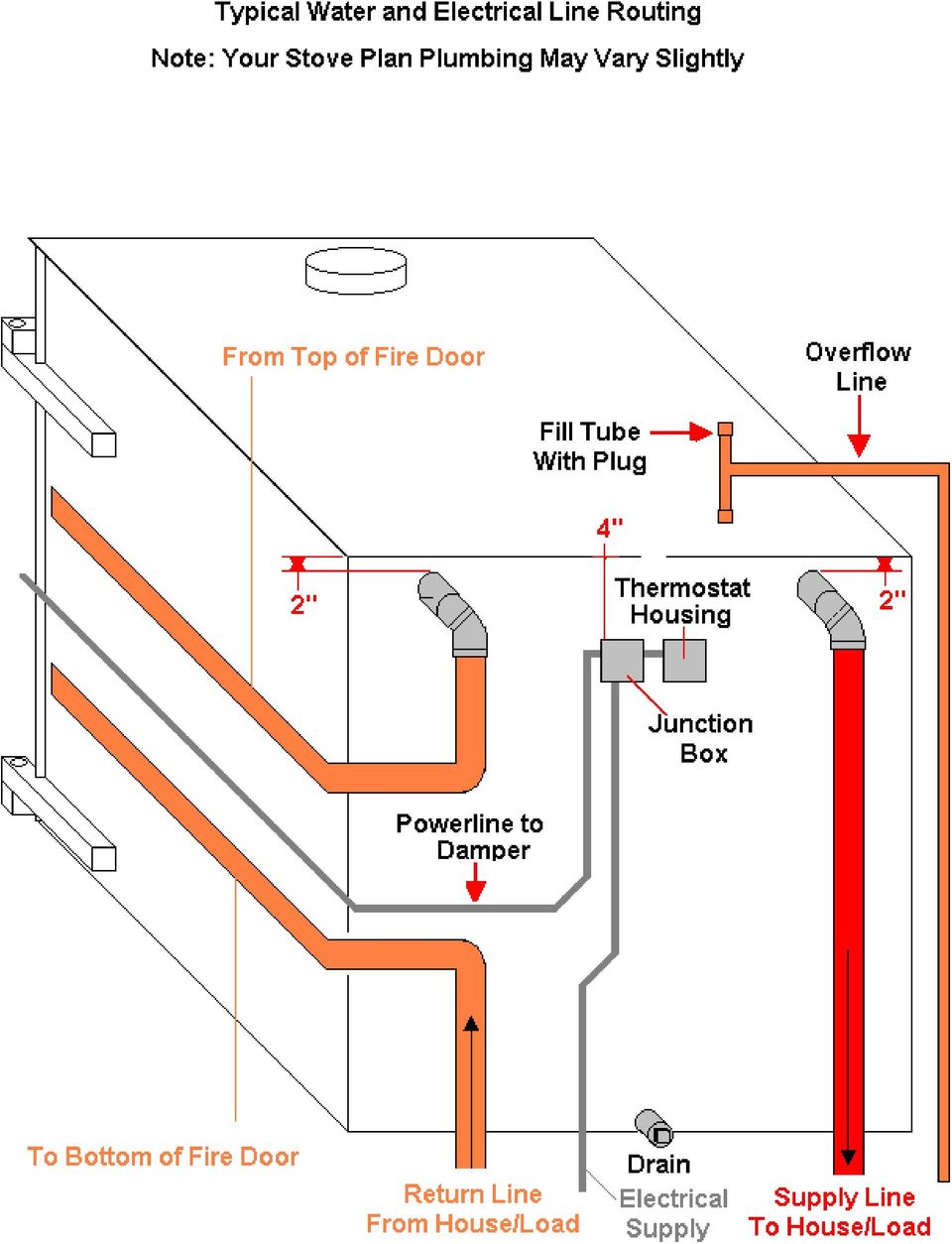
19 BOILER PLAN FREQUENTLY ASKED QUESTIONS AND ANSWERS How does the outside wood stove/boiler built from this plan work? This stove is basically, a very large firebox that is completely surrounded by water. A thermostat on the boiler water jacket energizes and de-energizes a powered damper assembly, to maintain a constant boiler water temperature. A low wattage pump moves this heated water to the house and back. What is the design of the delivery system that supplies the heated water to the house? I used 1-1/4" galvanized pipe that I obtained for free. Otherwise I would recommend, using 1"flexible copper or PEX tubing. Use long enough coil lengths to eliminate underground splices. The tubing should be well insulated with lengths of thick foam, pipe or fiberglass, insulation, or encased in 4" PVC, non-perforated sewer pipe, to keep moisture out of the pipe insulation. Do not use black poly pipe. It cannot take the heat, and will eventually crack. These supply and return waterlines, should be buried at least 12" deep. How often do you have to fill the fire box? That will depend on the outside temperature, and the size and insulation properties of your house. With my house (2300 sq. ft. plus a full basement) here in Wis., I fill my stove twice a day using softwood, until the temperature gets down to 0 degrees Fahrenheit. At that point I burn hardwood, but still only load twice per day. When the temperature is at, or above 20 degrees, once per day is sufficient. Can I use the boiler for other heating applications such as heating domestic hot water? Yes. It can be used to heat domestic hot water, a swimming pool as I do, or a hot tub/spa. This requires only a liquid to liquid heat exchanger, plans for, which are available from DEB Design. I have a forced air furnace in my house. Can this stove work in this application? Yes. There are 3 main ways this boiler can be used with any existing furnace system: 1) In a hydronic (hot water system) the hot water could be pumped directly to the boiler distribution manifold, and delivered to the various zones of the system as dictated by the zone thermostats. This is the method I currently use. 2) In a hydronic system, a liquid to liquid heat exchanger could be installed. The wood boiler water would be pumped into the exchanger, which would then heat the house system water, when the zone thermostats open and allow water flow through the exchanger. 3) In a forced air system, the boiler water would be pumped continuously through a liquid to 193

20 liquid heat exchanger that is installed in the furnace plenum, just like an air conditioning "A" coil. A simple control is installed to keep the furnace burner off, if the boiler supply water is hot enough. Then, when the house thermostat calls for heat, only the furnace blower is energized. In methods 2 and 3, the exchangers serve two purposes: 1) Supply heat to the house heating circuit. 2) Supply heat to the wood boiler circuit, too prevent freezing when the boiler fire goes out, if no antifreeze is used. DEB Design offers construction plans for a liquid to liquid heat exchanger. Liquid to air heat exchangers are available through most plumbing and heating retailers. Does it take superhuman welding skills to weld this boiler? I am interested in building such an outdoor heating apparatus. I would like to know what welding skills are necessary as I am a novice. I feel average welding skills are required to complete this project. It is constructed from cold rolled steel with mostly long straight 90 deg. butt welds. If you don't have average skills, I recommend you have a qualified friend, or even a welding shop, weld it for you. For a budgetary quote, plan on 100 hours to complete the welding. Unfortunately, if you are considering paying someone to weld or build your stove, you might just as well purchase a commercially built stove. How easy is it to change the plans? Could thicker steel be used? Can the plans be modified to include a slide out ash pan and grate system? This design is real flexible. The material list specifies the component sizes and assigns each piece a number. The plan drawings explain the assembly sequence, and show how the numbered pieces fit together. Using thicker steel would not be any problem. Extending the firebox length to 6', as an example, would involve adding 24" to the length of the appropriate pieces. This could take a bit of studying; however, it could be done. I once thought about installing an ash pan and did use a grate system, for a while. The grate didn't stand up very well, so I finally just left the ashes to serve as the bed. This has worked out quite well for me. I usually remove the ashes every 2 to 3 weeks. I do this prior to a reload session. I push the embers over to one side, and then shovel out half the box, and then repeat with the other half. Once done I refill the firebox. The residual embers easily restart the fire. It does get a bit smoky on occasion, but otherwise it's quite trouble free. If an ash pan/grate system was desired, I feel that one could be designed and installed, without too much trouble. Some heaters use an insulated door instead of a water filled door. Wouldn't that be simpler? Yes, it probably would be simpler. I was concerned about safety, and insuring that no exterior boiler surfaces became hotter than the boiler water temperature. This also could be left to the builder's discretion. What would be the life expectancy of the ¼ thick steel. 194
 Supply heat to the wood boiler circuit, too prevent freezing when the boiler fire goes out, if no antifreeze is used. DEB Design offers construction plans for a liquid to liquid heat exchanger.")
21 That will depend on how leak free the fire box is made. The enemy here is rust, not heat. If the inside of the firebox stays moisture free, I would expect it to last many years. I also think that using a rust inhibitor (automotive) in the boiler water, would help promote a long boiler life. The first thing that I was wondering is how do you fill your boiler with water? Do you fill it with a hose? I have a water supply line plumbed into the circuit, inside my house. How many gallons do you think you fill each week? I usually only have to add a gallon per month or so. Have you thought of installing anode rods similar to water heaters? No, but that's an excellent idea. They would need to be installed along either of the sides where there is enough depth. Would four or five pieces of metal tubing run horizontally in the top of fire box be an easy way to improve efficiency? It might. There is any number of ways to improve the efficiency of the design. The plan, as built, was meant to be a starting point, for stove builders. More capable and advanced builders could easily add modifications of their own, but remember: Simpler is better! In your design, your supply and return lines both go to or near the top of the boiler. Why don't you return to the bottom of the boiler? This method provides protection in the event of a major, door hose break. If the outlet is positioned properly, the boiler water level would only drop to 1" above the firebox, which would keep water above the thermostat level. This would then keep the stove from thermal run-away, and subsequent destruction, and/or possible fire. Many commercially distributed wood boilers boast a firebrick lining in the firebox. Your plan doesn't. Do you recommend it for your boiler design? I don't know what the advantage of the firebrick would be in my design. Do the plans show how to hook up the boiler to a forced air heating system? No, you should consult a heating contractor for that phase of the project. 195
22 I'm somewhat reluctant to build a boiler such as this as I'm not an experienced welder. What are your thoughts on this? You might want to consider Boiler Plan II. It's easier, and cheaper to build than Boiler Plan I and would provide you with valuable experience, should you ever want to build a more complex version. What is the difference between a closed system and an open system? A closed loop system is not vented to the outside atmosphere (such as a hydronic heating system) while an open system is. DEB Design stoves plans use an open system. What advantages and disadvantages does each have? The main advantages of a closed loop are: 1) There will be very little oxygen in the water, which can shorten heating system component lives. (Pumps, valves, etc.) 2) There won't be any evaporation of the boiler water. The main advantage of an open system is that the components do not have to be as strong to withstand the higher pressures prevalent in a closed system. Do you have any plans for a system that holds less water? No, but the plans can be easily modified by the builder. Can you use a boiler to heat two buildings? Yes, all you do is run a plumbing (including pump and thermostat) loop from the boiler to the building to be heated. Can this unit be setup, so that if the fire goes out the gas furnace will take over? Yes, a Plumber can assist with this I currently have a 4,600 sq. ft. home with a 430 sq. ft. garage and a 16 by 30 ft. indoor swimming pool. We are using a 225,000 B.T.U gas boiler to heat our home. This boiler operates at 18 psi with an expansion tank. Will your wood boiler work with our present system with the gas boiler used only for a backup? I've estimated the DEB Design Boiler Plan I boiler at app. 125,000 BTUs. You'd need to use liquid to liquid heat exchangers to integrate the outside wood stove into your existing heating system. I've estimated the DEB Design exchanger plan design BTU rating at app. 50,000, so you'd need at least 5 of the exchangers and a large enough wood boiler to match your current stove capacity. (Plus a whole lot of wood to fuel it) 196
23 How large of a boiler will I need in the previous question? About twice the size of the plan design which has a 36 cubic ft. capacity firebox. (In theory) Are the plans for Boiler I and Boiler II different size boilers? No, they have the same size firebox. What are the BTU ratings of the plan boilers? Approximately 125,000 BTUs. Do you ever or frequently have problems pushing water with your small ground Grunfos pump? Have you ever had the situation where your pump won't push air, but it will push water? Do you have any ideas as to why I am running into so much trouble with the pump quitting pumping the cycle? Yes, I've had the same problems with air in the lines, especially the first year, when I used poly pipe for supply and return lines. Leaks will cause this. Also, the Grunfos pump may not pump water up hill very well. A critical design element is the nipple length, shown on the "Side View" of Drawing 15. (Size the pipe nipple length to end 1" above the firebox) This creates a fluid locked water circuit, between the boiler supply and return outlets. Once all the air is purged from the lines, the Grunfos pump can "move" water continually, with out problems, as long as there are no major water leaks. If you don't construct the boiler return entry like this, you won't be able to use a Grunfos pump. You may need a stronger pump. (More electrical power consumption) In my own installation I placed an old jet pump ahead of the Grunfos pump that I use for purging air out of my system. (It also serves as a back up pump)i must always be careful to insure that at least 1 heat circuit is open; otherwise the pressure from the auxiliary pump will trip the high pressure relief valve on my natural gas commercial boiler (usually set at about 30#). As you can surmise, I have my heating systems integrated. Once all the air is purged from the system, the auxiliary pump is shut off, and the small circulating can pump just fine. If you are using a radiator as a heat exchanger, the auxiliary pump should be installed on the return side. This would insure that the radiator is not exposed to excessive pressure. How do I seal around the chimney, high temp silicone? Use a chimney collar. This is a piece of steel that wraps tightly and fastens around the flue pipe. It flares down and out, a few inches. High temp sealant could be used to complete the seal between the collar and flue pipe. In my heating application the forced air system is in the attic and I would want to use a coil in the air handler. Have you had any experience with pumping the water up to the second story 197
24 of a house? 1) Yes, once all the air has been pumped out of a heating loop as you describe, a circulation pump is all that is needed. That's because the weight of the water in the return line draws the water up through the supply line through a siphoning action. The circulation pump specified in the plans should work just fine. 2) Another more economical option for forcing air out of any heating zone loop is to flush it out using the house supply water. All you need do is close the boiler supply valve and then fully open the house water supply valve. Since the boiler supply line is closed, the water will flow through the heat circuit and back to the boiler through the return line until all the air has been purged from the line. Does it really take 100 hours to weld? Answer Yes, at least, plus many more hours to install, plumb, and troubleshoot. This project is not something you would want to hire done. If you are considering that, you should purchase a commercial version. It would be better to ask a family member or friend for help. How much should I expect to pay for a good welder? f you must pay to have the welding done, you might as well just buy a commercial unit. I suggest you should shop around for someone willing to do the project as a side job rather than as a livelihood. How long does it take to get the parts I would need? The steel can usually be ordered and picked up within a week s time. The remainder of the parts can be usually be obtained locally, or via UPS. Are you still using the same unit in the plans? (Boiler Plan I) No, that stove was built in 1995, I am on the second revision (of sorts). The pallet burner is what I currently use. What changes did you make on your current stove? I did away with the extra baffle and changed the powered draft system so the stove is more efficient. Do you wish you would had changed anything else? Yes, when I build another stove I would run the flue straight up from the top of the firebox and omit the horizontal section. I had originally built it that way to make it easier to install the boiler roof. I would also make sure to place the overflow pipe towards the south to prevent it 198
25 from freezing up! How long has your current stove been in use? My current stove was built in September of 2002, and has been in use for at least 8 months every year since. I'm considering buying and building the large boiler plan for the house and the smaller one for my workroom. I'd build just one big one and pipe the water to both locations. You will definitely need a liquid to air heat exchanger. Some stove builders have used truck radiators for this purpose. I was thinking of installing this in a garage. Would this be inappropriate? These stoves are not meant to be installed indoors. The large size of the firebox doors would allow smoke to completely engulf the indoor space. One of the biggest reasons for the popularity of these stoves is their safety due to the outdoor placement. Are the same controls used for all stove plans and if not can the plan 1's be "used" for plan 2's. The control systems specified are slightly different, but you could use the Boiler Plan I control system for any stove you build. Can you give me with the overall firebox capacity of Boiler Plan I and II? Both plans have approximately the same firebox dimensions, yielding approximately 36 cubic feet of volume. Boiler Plan I is rectangular in design while Boiler Plan II is circular due to the use of drums and tanks for it's construction. If you have the appropriate raw materials, Plan II is a great way to economically get your feet wet in boiler stove construction. I used fiberglass construction insulation that I stripped the paper backing off of. It is shown on page 48 and 49 of the pallet burner plan. Any type of insulation can be used as long as it is not flammable including blown in types of insulation called cellulous. These are treated with fire retardant chemicals. You could weld up the insulation cavity leaving the top piece off and then mount the door to the stove (Or weld the insulation cavity onto the door after it is mounted). You could then pour the cellulous style insulation into the door cavity until filled and then install the top piece. You should make the top piece removable so additional insulation can be added later if it settles. (Be sure that a draft way is incorporated into the door insulation cavity.) If I do not use a blower as shown in your plans, I assume I will need a damper door of some type. If that is correct, how would you activating the open/close of the door. The damper motor that is specified is actually used to activate the steam damper doors on 199
26 large steam heated tumblers. In that application, the motor shaft is coupled to a 1" diameter shaft. A small gauge chain is attached between the shaft and the damper doors. When the damper motor activates it draws the chain onto the shaft which pulls open the damper. The stove damper could be a simple 8" wide x 16" high plate that is hinged at the top and covers the draft way opening in the door. The damper could be weighted at the bottom to insure closure and have an arm that extends outward a few inches from the top. You could attach the chain to this arm and mount the damper motor and weatherproof enclosure directly above the damper motor. You would probably also want to install a positive stop to the damper door so that it only opens a few inches at the bottom. You might also be able to use a solenoid to accomplish the same task; however it has been my experience that the hard quick pull of solenoids can be hard on components and linkages. Is it possible to use coal in these stoves? Though I've never tried it, using coal should not be a problem. The only thing that you would want to insure is that the loading door has a good seal with the firebox. If air is not cut off to the fire when the damper closes, the coal could burn out of control and overheat the water causing it to boil off. If this goes on for too long, too much water could evaporate to the point that the firebox becomes exposed. If this happens, the stove could be destroyed. (Welds tearing, steel warping, etc). I suggest that if you build a stove for this purpose, that you pay extra attention to the door seal areas. On the initial fire up, do not overload with coal until you are sure the fire can be properly controlled. (Or there is more of a load on the stove such as during colder weather). I have your plans and in the process of building my stove. Not clear on how high the water level should be above the circulating pump fitting. The plans show a centerline dimension of 3" to the top of the stove. The water jacket of the stove should be filled to the top until or until it flows out the over flow. The assumption is that if you use 1" or 1-1/4" pipe for your supply line, that there will be at least 2-1/2" to 2-3/8" of water above the highest part of the outlet. I just purchased a CD on how to construct a wood stove/boiler. Is there any way to print a copy of these plans from the downloaded program? Yes, if you have a printer hooked to your PC, you should be able to open the file and then send it to the printer. If you do not have a printer attached, you could possible the file or transfer with a data storage device such as a CD, to someone with a printer. They could then print it from their PC using their printer. I am interested in purchasing one of your CDs. I assume I will be able to produce shop drawings from this CD? The plan files are all Adobe Acrobat files. I do not know exactly what your shop drawing 200
27 requirements are but the files can easily be printed to a printer or drawing plotter. The plans are normally printed to a standard paper size of 8-1/2" x 11". How long will the Pallet Burner take to burn up 12 pallets, before needing to be refilled? The time will vary depending on the following factors: 1) The average daily winter temperature of your location 2) The insulation properties of the building or house 3) The wind conditions of the location The stove pictured in the plans was designed to heat a 2300 square foot house with the following conditions: 1) An outside temperature down to 0 degrees Fahrenheit 2) The house is 13 years old and is well insulated. 3) The wind speed averages up to 10 miles per hour. If these conditions are exceeded, the stove will need to be loaded twice per day. Copyright 2008 DEB Design. DEB Design assumes no Responsibility for the use of any of the materials or methods Described neither in this publication nor for the products thereof 201
Build a Pallet Fueled Outdoor Wood Stove. Copyright DEB Design 2003
 Build a Pallet Fueled Outdoor Wood Stove Copyright DEB Design 2003 Pallet Fueled Boiler Plan Table of Contents Cover Page Introduction Tabulated Parts List Damper/Other Parts List Additional Materials
Boiler Plan II Table of Contents
 Cover Page Table Of Contents Introduction Parts List Additional Materials Assembly instructions Drawings 1-15 Boiler Plan II Table of Contents Introduction This will be a very rewarding project, if you
I N S T A L L A T I O N I N S T R U C T I O N S F O R T H E H i l k o i l Energy S aving Hot Water Kit
 I N S T A L L A T I O N I N S T R U C T I O N S F O R T H E H i l k o i l Energy S aving Hot Water Kit IMPORTANT: These installation instructions are meant to be used as a guide for woodstove owners and
Replacement parts. WM97+ gas-fired water boiler Boiler Manual. OBTAIN PARTS ONLY THROUGH WEIL-McLAIN THE BOILER CONTAINS CERAMIC FIBER MATERIALS
 Replacement parts DO NOT SERVICE THE BOILER WITHOUT A WM97+ MAINTENANCE KIT AVAILABLE Failure to adhere to these guidelines can result in severe personal injury, death or substantial property damage. The
One Year Warranty. Stock U.S. # of Volts Weight CONN. Height Dia. Watts # GAL. Elements INS. Inches NATURAL GAS* Six Year Warranty
 One Year Warranty ELECTRIC Stock U.S. # of Volts Weight CONN. Height Dia. Watts # GAL. Elements INS. Inches Fused Ceramic Shield tank lining is corrosion-resistant for years of dependability. Adjustable
BUILT-IN DISHWASHER INSTALLATION INSTRUCTIONS
 BUILT-IN DISHWASHER INSTALLATION INSTRUCTIONS PLEASE READ COMPLETE INSTRUCTIONS BEFORE YOU BEGIN LEAVE INSTALLATION INSTRUCTIONS AND USER'S GUIDE WITH OWNER ALL ELECTRIC WIRING AND PLUMBING MUST BE DONE
SunMor SM-V30 Solar Water Heater Installation Manual
 SunMor SM-V30 Solar Water Heater Installation Manual Rev. 1.02 Congratulations on the purchase of your new SunMor SM-V30 from Nature s Comfort LLC! You must read this entire instruction manual before beginning
2010 Residential Water Heater Replacement Check List
 2010 Residential Water Heater Replacement Check List The intent of this check list is to provide installers a general reference for the enforcement of code requirements in the Greater San Diego Area. This
PARTS CATALOG RPPCR01111_Front_Backcx.indd 1 RPPCR01111_Front_Backcx.indd 1 11/21/11 1:41 PM 11/21/11 1:41 PM
 PARTS CATALOG RPPCR01111_Front_Backcx.indd 1 11/21/11 1:41 PM RELIANCE Has Everything Your Customers Need to Do the Job Right! Reliance Water Heater Company was founded in 1981 to provide a water heater
Installation Instructions
 Installation Instructions Built-In Dishwasher If you have questions, call 1-800-4-MY-HOME (1-800-469-4663) or visit our website at: www.sears.com BEFORE YOU BEGIN Read these instructions completely and
GEET Fuel Processor Plans
 GEET Fuel Processor Plans This is a greatly simplified Proof of Concept version of the GEET Fuel Processor that just about anyone can build from parts from a local Hardware store in a weekend for very
specializing in AIR CONDITIONING, PARTS AND SYSTEMS for your classic vehicle PERFECT FIT IN-DASH HEAT/ COOL/ DEFROST 1967-72 CHEVROLET PICKUP
 specializing in AIR CONDITIONING, PARTS AND SYSTEMS for your classic vehicle PERFECT FIT IN-DASH HEAT/ COOL/ DEFROST 1967-72 CHEVROLET PICKUP CONTROL & OPERATING INSTRUCTIONS The controls on your new Perfect
Electrical for Detached Garages: Updated Feb 19, 2016 for 2015 CE Code in force Jan. 1, 2016. Underground branch circuit feeding a detached garage:
 Electrical for Detached Garages: Updated Feb 19, 2016 for 2015 CE Code in force Jan. 1, 2016 * Garage construction requires permits (electrical, building) * Permits must be applied for at the time. * Dial
Installation Manual. Solar Pool Heating System. Read the complete manual before beginning the installation
 Solar Pool Heating System Installation Manual Read the complete manual before beginning the installation 1. Sizing the System Visit www.techno-solis.com to size the system using the sizing calculator.
the stainless steel water-heater for your woodstove USER S MANUAL
 the stainless steel water-heater for your woodstove USER S MANUAL Get Into Hot Water... Heating water while heating the home with renewable wood has been done for centuries and is now reemmerging as a
Solstice/Sky Water Pump Replacement
 Solstice/Sky Water Pump Replacement The water pump on the Solstice/Sky is starting to need replacement on some vehicles. This guide will help in replacing the water pump while the engine is still in the
CDS TROUBLESHOOTING SECTION I. VACUUM. 1.0. Weak vacuum at wand. Gauge reads normal (10hg to 14hg)
") CDS TROUBLESHOOTING SECTION I. VACUUM 1.0. Weak vacuum at wand. Gauge reads normal (10hg to 14hg) 1.1. Clogged hoses or wand tube. Disconnect hoses and carefully check for an obstruction. 1.2. Excessive
CDS TROUBLESHOOTING SECTION I. VACUUM 1.0. Weak vacuum at wand. Gauge reads normal (10hg to 14hg) 1.1. Clogged hoses or wand tube. Disconnect hoses and carefully check for an obstruction. 1.2. Excessive
Power Cube Open Source Ecology Page 1. Power Cube. Version 4
 Power Cube Open Source Ecology Page 1 Power Cube Version 4 Power Cube Open Source Ecology Page 2 Contents Table of Contents Power Cube... 1 Contents...2 Introduction... 3 Bill Of Materials...4 Discrete
Select Radiators Installation Guide
 Select Radiators Installation Guide Table of Contents Informational Symbols...3 Before You Begin...4 Select Rough-In... 5 Connection Installation...6 Optional Piping Arrangements...7 Conventional Wall
Installation Instructions For Slider Casement Air Conditioners
 Installation Instructions For Slider Casement Air Conditioners NOTE: These instructions describe installation in a typical wood framed window with a wood SLIDE-BY sash, or installation in a metal CASEMENT
Installation Instructions
 Installation Instructions One-Piece Deep Wall Sleeve For Use with Packaged Terminal Units Please read these instructions completely before attempting installation. NOTE: Ensure that the unit is only installed
Slide the new steering column shaft through the steering column from the driver compartment.
 Slide the new steering column shaft through the steering column from the driver compartment. Push the column shaft through the steering column until the machined end is out past the column lower bushing.
Constantemp Double Wall Low pressure steam-water Heater F-340LDW,F-640LDW, F-940LDW and F-1240LDW
 Installation, Operating and Maintenance Instructions 90/4.5.5 Rev. 0 Constantemp Double Wall Low pressure steam-water Heater F-340LDW,F-640LDW, F-940LDW and F-1240LDW Table of Contents SECTION I... 2 INSTALLATION...
STEADYfast Stabilizer Installation Notes Fifth Wheel and Travel Trailers 11/23/13
 STEADYfast Stabilizer Installation Notes Fifth Wheel and Travel Trailers 11/23/13 (See Supplemental Instructions for trailers with heavy duty round footplates and/or Power Leveling Systems) PHONE SUPPORT
UB1 AIR CONDITIONING UNIT INSTALLATION INSTRUCTIONS
 UB1 AIR CONDITIONING UNIT INSTALLATION INSTRUCTIONS INSTALLATION INSTRUCTIONS: Carefully read these instructions before installing your new air-conditioner. AUSTRALIAN AUTOMOTIVE AIR AL00500054E 1 Table
1 DESCRIPTION OF THE APPLIANCE
 1 DESCRIPTION OF THE APPLIANCE 1.1 INTRODUCTION The cast iron SF boilers are a valid solution for the present energetic problems, since they can run with solid fuels: wood and coal. These series of boilers
INSTALLATION OF A BAY WINDOW
 INSTALLATION OF A BAY WINDOW Installation of a Bay Window These instructions relate to the replacement of an existing bay window or replacement of a straight window with a new bay window, in an opening
Installer s Guide 18-AH39D1-13
 18-AH39D1-13 Cased Aluminum "Convertible" Coils 4TXCA018BC3HC** 4TXCA024BC3HC** 4TXCB025BC3HC** 4TXCB026BC3HC** 4TXCB031BC3HC** 4TXCB032BC3HC** ALL phases of this installation must comply with NATIONAL,
Acumen Enterprises, Inc.
 Hourly rates Discount w/o Rebate Electrician $78.00 10% $70.20 $70.73 HVAC Technician $78.00 10% $70.20 $70.73 Insulator $42.00 10% $37.80 $38.08 Sheet Metal Worker $74.00 10% $66.60 $67.10 Plumber/Pipefitter
OWNER S MANUAL FORCE 10 MARINE COMPANY 23080 HAMILTON ROAD RICHMOND, BC CANADA V6V 1C9 TEL: (604) 522-0233 FAX: (604) 522-9608
 522-0233 FAX: (604) 522-9608") Electric Water Heater OWNER S MANUAL FORCE 10 MARINE COMPANY 23080 HAMILTON ROAD RICHMOND, BC CANADA V6V 1C9 TEL: (604) 522-0233 FAX: (604) 522-9608 If your water Heater is Damaged or you have questions
Electric Water Heater OWNER S MANUAL FORCE 10 MARINE COMPANY 23080 HAMILTON ROAD RICHMOND, BC CANADA V6V 1C9 TEL: (604) 522-0233 FAX: (604) 522-9608 If your water Heater is Damaged or you have questions
HALE PET DOOR INSTALLATION INSTRUCTIONS HALE STANDARD PANEL MODEL
 HALE PET DOOR INSTALLATION INSTRUCTIONS HALE STANDARD PANEL MODEL Please read these instructions carefully and completely before attempting to install Hale Pet Doors; they will guide you through the steps
VOYAGER 570G. 744A Sprayer Control
 VOYAGER 570G 744A Sprayer Control U S E R M A N U A L U S E R M A N U A L Table of Contents CHAPTER 1 - INTRODUCTION...1 SYSTEM CONFIGURATIONS...1 KIT CONTENTS...3 CONTROL HOUSING ASSEMBLY...5 CHAPTER
Overview PARTS LIST. B. Lever mounting base C. Flush handle assembly D. Grey/Blue float stop E. Grey float (Full Flush) F. Flush valve washer
 F. Flush valve washer") Overview READ ENTIRE INSTRUCTIONS BEFORE STARTING INSTALLATION PARTS LIST A. Flush valve B. Lever mounting base C. Flush handle assembly D. Grey/Blue float stop E. Grey float (Full Flush) F. Flush valve
Overview READ ENTIRE INSTRUCTIONS BEFORE STARTING INSTALLATION PARTS LIST A. Flush valve B. Lever mounting base C. Flush handle assembly D. Grey/Blue float stop E. Grey float (Full Flush) F. Flush valve
Installation Instructions - For the following HEATER model numbers: 200, 300, 400, 500 Series Hydronic Heaters
 Marine Heater Installation Instructions - For the following HEATER model numbers: 200, 300, 400, 500 Series Hydronic Heaters Approximate Installation Time: 3-5 Hours Tools Required: #2 Phillips Screw Driver;
Cooktop Low-Profile Ventilation Hoods
 INSTALLATION GUIDE Cooktop Low-Profile Ventilation Hoods Contents Wolf Cooktop Low-Profile Ventilation Hoods........ 3 Cooktop Low-Profile Hood Specifications.......... 4 Cooktop Low-Profile Hood Installation............
Your safety and the safety of others are very important.
 NATURAL GAS TO PROPANE CONVERSION KIT 090 INSTALLATION INSTRUCTIONS FOR ALTITUDES 0 -,00 FT. ONLY PROPANE CONVERSION KIT SAFETY... INSTALLATION REQUIREMENTS... Tools and Parts... LP Gas Requirements...
Utility Distribution Systems
 Utility Distribution Systems 6/2012 A0011037 1 WARRANTY This equipment is warranted to be free from defects in materials and workmanship, under normal use and service, for a period of 12 months from date
W I T H I N J O I ST S I N STA L L AT I ON
 Radiantec W I T H I N J O I ST S I N STA L L AT I ON I N S TA L L AT I O N S U P P L E M E N T 260 Joists When tubing is placed beneath a joisted floor system, it is weaved between the joists and supported
AMX300 DirectConnect Mixing Valve Kits
 AMX300 DirectConnect Mixing Valve Kits INSTALLATION INSTRUCTIONS Tools needed (not supplied) 1. Wrench 2. Pliers Safety Definitions These safety terms identify information you must read. CAUTION Indicates
CAST IRON THE BASICS. Heatline - Cast Iron Radiators SMOOTH FLAT FILE TO REMOVE ANY SWARF. ONE TIME. ASSEMBLY. JOINTS SHOULD BE TIGHTENED.
 CAST IRON THE BASICS 1. DO NOT LIFT ON YOUR OWN. 2. ONLY LIFT THE RADIATOR VERTICALLY. 3. DO NOT LIFT MORE THAN 8/10 SECTIONS AT ANY ONE TIME. 4. POSITION THE RADIATOR BEFORE FINAL ASSEMBLY. 5. THIS PRODUCT
Installation Instructions
 READ BEFORE INSTALLING UNIT For Slider Casement Air Conditioners To avoid risk of personal injury, property damage, or product damage due to the weight of this device and sharp edges that may be exposed:
Watts Spacemaker. Sa f e t y Wa t e r He a t e r. Enclosures Stands Restraints
 Watts Spacemaker Sa f e t y Wa t e r He a t e r Installation Products Enclosures Stands Restraints Ta b l e o f Co n t e n t s / In t r o d u c t i o n / Seismic Zo n e s Table of Contents Seismic Zones
Installation Instructions
 VentilAire IV Whole-House Fresh Air Supply System Installation Instructions 914228 Flat Roof Kit 914229 Sloped Roof Kit 5" x 11' Class I Insulated Flexible Duct Plastic Clamps (2) Metal Clamps (2) Ceiling
MFH-5057 Ford Small-Block V-8 Fresh Water Cooling Kit Instructions
 MFH-5057 Ford Small-Block V-8 Fresh Water Cooling Kit Instructions MONITOR PRODUCTS, INC. 15400 Flight Path Dr Brooksville, FL 34604 Tel: 1-800-334-4591 or 352-544-2620 Sales: ext 201 Technical Support:
Plumbing. Helpful Hints Residential Construction. Lincoln County. Bert Polk Plumbing Inspector
 Plumbing Helpful Hints Residential Construction Bert Polk Plumbing Inspector Lincoln County 2015 Waste and vent fittings Vent 90 medium 90 long 90 1/16 bend,1/8 bend,1/6 bend, medium 90 san tee combination
DANGER DANGER. General Information. Safety Is Your Responsibility. Ordering Parts. Contact Information
 Safety Safety Is Your Responsibility DANGER To avoid personal injury or death, carefully read and understand all instructions pertaining to the Anthony Liftgates product. Do not attempt to install, operate,
WHAT YOU DON T KNOW ABOUT ACCUMULATORS CAN KILL YOU!
 WHAT YOU DON T KNOW ABOUT ACCUMULATORS CAN KILL YOU! Atlanta (Monroe) GA 770-267-3787 gpm@gpmhydraulic.com www.gpmhydraulic.com What You Don t Know About Hydraulic Accumulators Can Kill You TABLE OF CONTENTS
During severe flood events, such as those
 Recommended Practice for Home Heating Oil Tank Flood Resistance During severe flood events, such as those occurring from Hurricane Irene and Super- Storm Sandy, many coastal and low elevation inland areas
Air Conditioner Water Heater Model ACWH18
 Air Conditioner Water Heater Model ACWH18 Installation Guide IMPORTANT! READ THIS FIRST! Commissioning of this unit must be done by a licensed HVAC technician. Commissioning includes making the electrical
Installation Guide for the TJ LCG PRO Suspension System (Low Center of Gravity) Available 4 or 5
 Available 4 or 5") INSTALLATION GUIDE Installation Guide for the TJ LCG PRO Suspension System (Low Center of Gravity) Available 4 or 5 Take every precaution to make this installation a safe procedure. Make safety the number
INSTALLATION GUIDE Installation Guide for the TJ LCG PRO Suspension System (Low Center of Gravity) Available 4 or 5 Take every precaution to make this installation a safe procedure. Make safety the number
Installation Instructions 4508 4508S
 SYMPHONY Spread Lavatory Faucet with Speed Connect Drain Congratulations on purchasing your American Standard faucet with Speed Connect drain, a feature found only on American Standard faucets. Speed Connect
HOW TO-SOLAR HOT WATER
 HOW TO-SOLAR HOT WATER GREENPOWERSCIENCE.COM February 21,2008 Heat your water or home for less than $500. Heating water for a shower or water to circulate in a floor radiator or underfloor heating system
Coal fired steam locomotive CHARYBDIS
 Coal fired steam locomotive CHARYBDIS Owners Manual Contents Locomotive running tools Controls Running in Preparing to run your locomotive Running your locomotive Once you have finished your running session
SRA-125/SRAX-125 Double-Rail Lift-Out Rail System Installation & Service Manual with Parts List
 SRA-125/SRAX-125 Double-Rail Lift-Out Rail System Installation & Service Manual with Parts List For MG, WG, WGL, and Grinder Pumps for Effluent & Sewage CAUTION! Read these safety warnings first before
PSS10H/B PSS12H/A ILLUSTRATED PARTS LISTS
 PSS10H/B PSS12H/A ILLUSTRATED PARTS LISTS AC AND DC GENERATOR SCHEMATIC ENGINE GENERATOR ASSEMBLY REF Description QTY PSS10 PSS12 1 Engine, Honda GX620K1VXC2 Code 637220 1 99779-000 GX670VXC2 Code 637220
INSTALL INSTRUCTIONS KK-C-HVAC-1 HVAC UNIT 2003-2014 CHEVROLET/GMC VANS FOR
 INSTALL INSTRUCTIONS KK-C-HVAC-1 HVAC UNIT 2003-2014 CHEVROLET/GMC VANS FOR (For NEW 2007 ALL WHITE KWIK-KITS ONLY) Warning do not attempt to install A/C units unless you are experienced with servicing
How To Launch A Rocket From A Formica
 Building the Basic Bottle Rocket Launch Pad Materials: -Formica double-sink countertop cutout. This can be easily and cheaply obtained from a local company that manufactures and/or installs countertops.
Indirect-Fired Storage Water Heater Models WH-30 through WH-80 INSTALLATION AND OPERATING INSTRUCTIONS
 Indirect-Fired Storage Water Heater Models WH-30 through WH-80 INSTALLATION AND OPERATING INSTRUCTIONS Contents Page Ratings and Specifications..................... 2 Installation Requirements......................
All content including text and photographs are protected by law - Copyright 2010 by www.vldesign.com
 Step by step directions for building your own 1500 gallon aquarium, 350 Gallon Sump, and a radiant heater. PART 1 Building the aquarium PART 2 Building the sump PART 3 The plumbing PART 4 The radiant heater
PIPES AND TUBES FOR HVAC PIPING AND EQUIPMENT
 PIPES AND TUBES FOR HVAC PIPING AND EQUIPMENT GENERAL INFORMATION 1.1 This section applies to piping systems for chilled water, hot water, condenser water, steam, condensate return, fuel oil, refrigerant
ASK THE EXPERT: Burner Troubleshooting Information & Maintenance
 ASK THE EXPERT: Burner Troubleshooting Information & Maintenance The burner is the heart of your BBQ. It is subject to a number of conditions that can cause damage, and lead to potential safety issues.
DIY Poly Digester. What is Supplied in the Kit. Sketch of Arrangement
 DIY Poly Digester What is Supplied in the Kit 4 m of clear polyethylene layflat tube Inlet tube (100mm PVC pipe, 40 cm long) 0.4 m of 19mm dia PVC pipe 0.4 m of 13mm dia black poly tube 2 m of 12 mm dia
Float and Thermostatic Traps Series H, C and X
 Hoffman Specialty Installation & Maintenance Instructions HS-(E) and Thermostatic Traps Series H, C and X Series C & NPT Series C NPT Series X NPT Series C NPT Series H Ratings Maximum Max. Operating NPT
Installation Instructions
 GE Consumer & Industrial Appliances Installation Instructions Junction Box Cover Within this user bag, you will find a junction box cover and a #10 hex head screw used to attach the junction box cover
OPERATING INSTRUCTIONS AND PARTS LIST FOR U075075 U100058 UNDERGROUND HOSE REELS
 OPERATING INSTRUCTIONS AND PARTS LIST FOR U075075 U0005 FORM NO.: 3-00 REV: RAIN BIRD CORPORATION ONE REELCRAFT CENTER COLUMBIA CITY, IN 675 (00) -33 / (60) - FAX: (60) -605 U0005 MODEL NUMBER SIGNIFICANCE
Not required for most applications Not required for most applications High pressure (12-803 provided) High pressure (12-803 provided)
 High pressure (12-803 provided)") ELECTRIC FUEL PUMPS P/N 12-801-1, 712-801-1, 12-802-1, 712-802-1, 12-815-1, & 712-815-1 FUEL PRESSURE REGULATORS P/N 12-803, 12-501, 12-804, 12-500, & 15812NOS Installation Instructions THESE INSTRUCTIONS
ELECTRIC FUEL PUMPS P/N 12-801-1, 712-801-1, 12-802-1, 712-802-1, 12-815-1, & 712-815-1 FUEL PRESSURE REGULATORS P/N 12-803, 12-501, 12-804, 12-500, & 15812NOS Installation Instructions THESE INSTRUCTIONS
Model H2, H3, H4 & H5
 INSTALLATION AND OPERATING INSTRUCTIONS FOR THE HARDY OUTSIDE WOOD BURNING HEATER Model H2, H3, H4 & H5 HARDY MANUFACTURING COMPANY, INC. 12345 ROAD 505 PHILADELPHIA, MS 39350 PHONE: (601) 656-5866 FAX:
Operators manual Basic water heater
 Operators manual Basic water heater Isotemp Basic water heater has been designed and produced to ensure that your water heater will give long and trouble free operation for many years. It is important,
TRANS-05, Torque Tube Removal, Rebuilding, and Installation
 TRANS-05, Torque Tube Removal, Rebuilding, and Installation Tools Metric Wrench Set Metric Socket Set Jack Stands (6 minimum) Floor Jack 8mm Cheesehead socket (also referred to as 12 point internal socket
SunMaxx Solar Filling Station Operating Instructions
 SunMaxx Solar Filling Operating Instructions Content 1. Declaration of conformity... 2 2. Introduction... 2 3. Transportation and unpacking... 4 4. Mounting and commissioning... 5 5. End of operation...
ADDING AN ELECTRIC AUXILIARY FAN TO RADIATOR STACK ON 03 ALPINE COACH
 ADDING AN ELECTRIC AUXILIARY FAN TO RADIATOR STACK ON 03 ALPINE COACH The original design of the 03 Alpine Coaches (and perhaps other years as well) did not include any kind of engine fan engage mechanism
INSTALLATION INSTRUCTIONS Fan Coil Replacement Coil Kit EBX & EBXX
 Fan Coil Replacement Coil Kit EBX & EBXX These instructions must be read and understood completely before attempting installation. These instructions covers the installation of replacement coil kit into
Guidelines for Earthquake Bracing Residential Water Heaters
 Guidelines for Earthquake Bracing Residential Water Heaters Department of General Services Division of the State Architect In accordance with the Health and Safety Code Section 19215, the Division of the
9,000lb capacity 4 Post Lift Installation Manual
 9,000lb capacity 4 Post Lift Installation Manual Parts Checklist 1 Main side track with 9/16 hole on cylinder end complete with cylinder, hose and connector 1 Offside track 2 Cross Rails pre-assembled
OVEN PARTS For Models:GSC308PJB05, GSC308PJQ05, GSC308PJT05, GSC308PJS05 (Black) (White) (Biscuit) (Black Stainless)
 (White) (Biscuit) (Black Stainless)") OVEN PARTS 30" BUILT IN ELECTRIC COMBO SENSOR/SC (GOLD LINE) 3 05 Litho In U.S.A. (cre) 1 Part No. Rev.A OVEN PARTS 1 Literature Parts 4455994 Installation Instructions Use & Care Guide 8300346 Microwave
OVEN PARTS 30" BUILT IN ELECTRIC COMBO SENSOR/SC (GOLD LINE) 3 05 Litho In U.S.A. (cre) 1 Part No. Rev.A OVEN PARTS 1 Literature Parts 4455994 Installation Instructions Use & Care Guide 8300346 Microwave
Installation of Rear View Camera in a 1995 Roadtrek 190 Popular
 Installation Instructions: 1995 Roadtrek Rear View Camera Page 1 Installation of Rear View Camera in a 1995 Roadtrek 190 Popular Introduction. In the fall of 2010 we investigated rear view cameras for
MGB Chrome Bumper Conversion
 MGB Chrome Bumper Conversion Installation Instructions For 1974 1/2-1980 MGB This kit requires cutting, welding, and painting. Professional installation recommended. Note: Every MGB body is slightly different
H41 Electrical Stage Aft Air Conditioner Unit Installation
 Aft Air Conditioner Unit Installation 1. Place Air-Cond unit in A/C shelf with air return facing fwd direction of the boat. 2. Do not secure Air-Cond Unit on shelf, install both side of air condition ABS
GROWTH MANAGEMENT DEPARTMENT 201 SE 3 rd ST, (Second Floor), Ocala, FL 34471 (352) 629-8421; FAX: (352) 629-8264
, Ocala, FL 34471 (352) 629-8421; FAX: (352) 629-8264") BUILDING CODE GUIDELINE FOR MECHANICAL INSPECTIONS Building Code compliance is the obligation of design professionals and/or contractors. Plan Review and Inspection Guidelines are intended to be used by
BUILDING CODE GUIDELINE FOR MECHANICAL INSPECTIONS Building Code compliance is the obligation of design professionals and/or contractors. Plan Review and Inspection Guidelines are intended to be used by
PERFECT FIT SERIES IN-DASH HEAT/ COOL/ DEFROST 1967 CHEVROLET IMPALA
 specializing in AIR CONDITIONING, PARTS AND SYSTEMS for your classic vehicle PERFECT FIT SERIES IN-DASH HEAT/ COOL/ DEFROST 1967 CHEVROLET IMPALA CONTROL & OPERATING INSTRUCTIONS The controls on your new
Important: Please read these instructions carefully and completely before starting the installation. TITAN Fuel Tanks
 TITAN pt. no.: 03 0000 0120 Important: Please read these instructions carefully and completely before starting the installation. TITAN Fuel Tanks INSTALLATION INSTRUCTIONS G e n e r a t i o n V Extended
Guidelines for Earthquake Bracing of Residential Water Heaters
 Guidelines for Earthquake Bracing of Residential Water Heaters Department of General Services Division of the State Architect 1102 Q Street, Suite 5100 Sacramento, CA 95814 Phone: (916) 324-7099 Fax: (916)
HEAT PUMP FREQUENTLY ASKED QUESTIONS HEAT PUMP OUTDOOR UNIT ICED-UP DURING COLD WEATHER:
 HEAT PUMP FREQUENTLY ASKED QUESTIONS HEAT PUMP OUTDOOR UNIT ICED-UP DURING COLD WEATHER: It is normal for a heat pump to have a build up of white frost on the outside coil during cold damp weather. The
LU6X-130 Instructions and Parts List (including LU6X Basic) Operating Instructions
 Operating Instructions") LORTONE LU6X-130 Item # 061-092 LU6X Basic Item # 061-090 LU6X-130 Instructions and Parts List (including LU6X Basic) Operating Instructions Introduction The LU6X is one the most versatile pieces of equipment
LORTONE LU6X-130 Item # 061-092 LU6X Basic Item # 061-090 LU6X-130 Instructions and Parts List (including LU6X Basic) Operating Instructions Introduction The LU6X is one the most versatile pieces of equipment
Oil and Coolant Circulating Heating System. Model - OCSM
 Oil and Coolant Circulating Heating System Model - OCSM Installation & Operation Manual 216280-000 REV 2 Identifying Your System The HOTSTART heating system is designed to heat fluids for use in marine
Time needed: ~3h for lid replacement only. Add 1h for operation harness in lid and ~2h more for installing drive unit and cable harness in trunk.
 DIY for replacing trunk lid and/or retrofitting electrical operation of trunk lid. This document is meant to be a support and give advice on the procedure but I will take no responsibility for any damage
Geyser-R Heat pump water heater Installation manual
 Geyser-R Heat pump water heater Installation manual 1 Version 2.9 SAFETY INFORMATION Please read carefully to prevent serious accidents or injury. The Geyser-R Heat Pump Water Heater must be installed
Modular Locomotive System Instruction Manual for HBK8 George Body Kit
 Modular Locomotive System Instruction Manual for HBK8 George Body Kit Roundhouse Engineering Co. Ltd. Units 6-10 Churchill Business Park. Churchill Road, Wheatley. Doncaster. DN1 2TF. England. Tel. 01302
1. Lay out 2 pieces of 7/8" tubing and mark for bending as shown. Remember that the bend is in the shaded area as shown below in Figure 1.
 MINI BIKE PLANS Page 1 INTRODUCTION Before starting to build your Mini-Bike, be sure that you have all the parts shown on the material list. You will note that tubing has been used in the construction.
MODEL 2400 RAISED BED PLASTIC MULCH LAYER OPERATING MANUAL
 MODEL 2400 RAISED BED PLASTIC MULCH LAYER OPERATING MANUAL Rain-Flo Irrigation 929 Reading Road East Earl, Pa 17519 PH: 717-445-3000 Table Of Contents Bed Height...............................7 Cover Disk...............................9
11. COOLING SYSTEM 11-0 COOLING SYSTEM BET & WIN 50
 11 COOLING SYSTEM SERVICE INFORMATION------------------------------------------------ 11-1 TROUBLESHOOTING----------------------------------------------------- 11-1 RADIATOR ------------------------------------------------------------------
Industrial Strength Rocket Launcher
 Industrial Strength Rocket Launcher Description: Instructions for the construction of an industrial strength rocket launcher for use with paper rockets. Materials: Schedule 40 PVC piping and bushings from
Owner Retain this manual in a safe place to provide your serviceman information if it becomes necessary.
 INSTALLATION, OPERATING AND SERVICE MANUAL FOR EASY RADIANT WORKS HEATWAVE MODEL GH-25-40 GAS FIRED, VENTED INFRARED TUBE HEATER FOR RESIDENTIAL & COMMERCIAL / INDUSTRIAL APPLICATIONS. For Your Safety
INSTALLATION AND OPERATING INSTRUCTIONS For Model GL1 Gate Locks
 Securitron Magnalock Corp. www.securitron.com ASSA ABLOY, the global leader Tel 800.624.5625 techsupport@securitron.com in door opening solutions INSTALLATION AND OPERATING INSTRUCTIONS For Model GL1 Gate
Steam System Best Practices Condensate System Piping
 Steam System Best Practices Condensate System Piping Summary The best method for improving steam system energy efficiency, reducing chemical costs, and reducing make-up water costs is to return the maximum
POWERS Controls No. 4 Pneumatic Damper Actuator
 POWERS Controls No. 4 Pneumatic Damper Actuator Technical Instructions Document No. 155-032P25 AP 331-2 Actuator Assembly 331-2929 Typical Actuator Assembly 331-2904 Typical Actuator Assembly 331-3000
PROCEDURES PREVENTION OF ACCIDENTAL IGNITION
 Page No: 1 of 7 6.0 PURPOSE (192.751) All possible precautions shall be exercised to prevent the accidental escape and ignition of gas. Whenever possible, potential sources of ignition should be eliminated
WINTERIZING YOUR HOME PLUMBING AT BLUE RIDGE SHORES
 WINTERIZING YOUR HOME PLUMBING AT BLUE RIDGE SHORES The following are suggestions to help you winterize your home plumbing. They are for homes where the heat is not left on during the winter months. There
Stainless Steel Single and Dual Circulation Kits
 Instruction Sheet P/N 160780 01 Stainless Steel Single and Dual Circulation Kits Introduction The single and dual high-pressure circulation kits allow you to vary and control the circulation rate of coating
INSTRUCTIONS FOR USE, MAINTENANCE AND INSTALLATION OF THE
 SUN & HEAT SOLAR PRODUCTS INSTRUCTIONS FOR USE, MAINTENANCE AND INSTALLATION OF THE SOLAR DOMESTIC WATER HEATER THERMOSIPHON 150/2.5 (TYPICAL INSTRUCTIONS FOR A CLOSED LOOP THERMOSIPHONIC SYSTEM ON A FLAT