SNOWMOBILE OWNER S MANUAL RX10H/RX10SH RX10MH/RX10MSH RX10RH/RX10RSH LIT FA
|
|
|
- Joshua Frederick Russell
- 8 years ago
- Views:
Transcription
1 OWNER S MANUAL SNOWMOBILE RX10H/RX10SH RX10MH/RX10MSH RX10RH/RX10RSH LIT FA

2

3 A ESU MACHINE IDENTIFICATION Identification number records A. FRAME NUMBER: CZ-01E B B. ENGINE NUMBER (PRIMARY ID): CZ-01E C C. KEY NUMBER: CZ-01E Record the frame number, engine number (Primary ID), and key number in the spaces provided for assistance when ordering spare parts from a Yamaha dealer. 1 The frame number is the seventeen-digit number stamped on the frame of the snowmobile. (See fig. È.) 2 The engine number is stamped in the location as shown. (See fig. É.) 3 Key number (See fig. Ê.) Also, record and keep the ID numbers in a separate place in case the snowmobile is stolen.
 2 The engine number is stamped in the location as shown. (See fig. É.) 3 Key number (See fig. Ê.")
4 ESU INTRODUCTION Congratulations! Your choice of a Yamaha snowmobile assures you of the highest quality and dependability. Your Yamaha snowmobile is manufactured by a company well-known for excellence in the field of snowmobiles. The most advanced production equipment and technology have made Yamaha one of the best snowmobile manufacturers. We are confident that this snowmobile will meet the greatest expectations of our customers. This manual is designed to acquaint you with the operation of this snowmobile and minor maintenance required for satisfactory service. Should major repairs ever be required, you are advised to ask a Yamaha dealer to inspect and repair the snowmobile whenever it is necessary; they have the techniques, tools, and parts to ensure your satisfaction. We hope that the information within this manual will help you enjoy many hours of pleasure with your Yamaha snowmobile. RX10H/RX10SH RX10MH/RX10MSH RX10RH/RX10RSH OWNER S MANUAL 2002 by Yamaha Motor Corporation, U.S.A. 1st Edition, May 2002 All rights reserved. Any reprinting or unauthorized use without the written permission of Yamaha Motor Corporation, U.S.A. is expressly prohibited. Printed in Japan P/N LIT

5 PLEASE READ AND UNDERSTAND THIS MANUAL COMPLETELY BEFORE OPERATING THE SNOWMO- BILE. NOTE: Yamaha continually seeks advancements in product design and quality. Therefore, while this manual contains the most current product information available at the time of printing, there may be minor discrepancies between your snowmobile and this manual. If there is any question concerning this manual, please consult a Yamaha dealer. This manual should be considered a permanent part of this snowmobile and should remain with the snowmobile when resold. Particularly important information is distinguished in this manual by the following notations. The Safety Alert Symbol means ATTENTION! BECOME ALERT! YOUR SAFETY IS INVOLVED! Failure to follow instructions could result in severe injury or death to the snowmobile operator, a bystander, or a person inspecting or repairing the snowmobile. CAUTION: A CAUTION indicates special precautions that must be taken to avoid damage to the snowmobile. NOTE: A NOTE provides key information to make procedures easier or clearer.

6 ESU00003 CONTENTS YAMAHA MOTOR CORPORATION, U.S.A. SNOWMOBILE LIMITED WARRANTY YAMAHA EXTENDED SERVICE (Y.E.S.) LOCATION OF THE IMPORTANT LABELS SAFETY INFORMATION DESCRIPTION CONTROL FUNCTIONS Main switch Starter lever (choke) Throttle lever Engine overheating prevention system Throttle override system (T.O.R.S.) Speedometer unit High beam indicator light Fuel meter and grip/thumb warmer heat level indicator Fuel level warning indicator Oil level warning indicator Low coolant temperature indicator light Coolant temperature warning indicator Self-diagnosis warning indicator Engine stop switch Brake lever Parking brake lever Shift lever Headlight beam switch Shroud latches Drive guard V-belt holders Storage compartment PRE-OPERATION CHECKS Fuel Engine oil Engine oil level Coolant Throttle lever Throttle override system (T.O.R.S.) Brake Brake fluid leakage V-belt Drive guard Drive track mm (2.0-in) high-profile pattern drive track Slide runners Skis and ski runners Steering system Lights Air filter Fittings and fasteners Tool kit and recommended equipment OPERATION Starting the engine Break-in Riding your snowmobile Getting to know your snowmobile Learning to ride your snowmobile To start out and accelerate Braking Turning Riding uphill Riding downhill Traversing a slope Ice or icy surface Hard-packed snow...7-6

7 Operation on surfaces other than snow or ice Maximizing drive track life Strap Driving Stopping the engine Transporting Chassis Electric WIRING DIAGRAM PERIODIC MAINTENANCE Periodic maintenance chart Tool kit Spark plug inspection Engine idle speed adjustment Throttle cable adjustment Carburetor adjustment High altitude adjustments Adjusting the valve clearance Changing the engine oil Cooling system V-belt replacement Checking the oil level of the drive chain housing Checking the brake pads Checking the parking brake pads Checking the brake fluid level Brake fluid replacement Suspension Drive track adjustment Ski alignment Handlebar adjustment Lubrication Headlight bulb replacement Headlight beam adjustment Battery Fuse replacement TROUBLESHOOTING STORAGE SPECIFICATIONS Dimensions Engine

8 ESU YAMAHA MOTOR CORPORATION, U.S.A. SNOWMOBILE LIMITED WARRANTY CW-01E 1-1

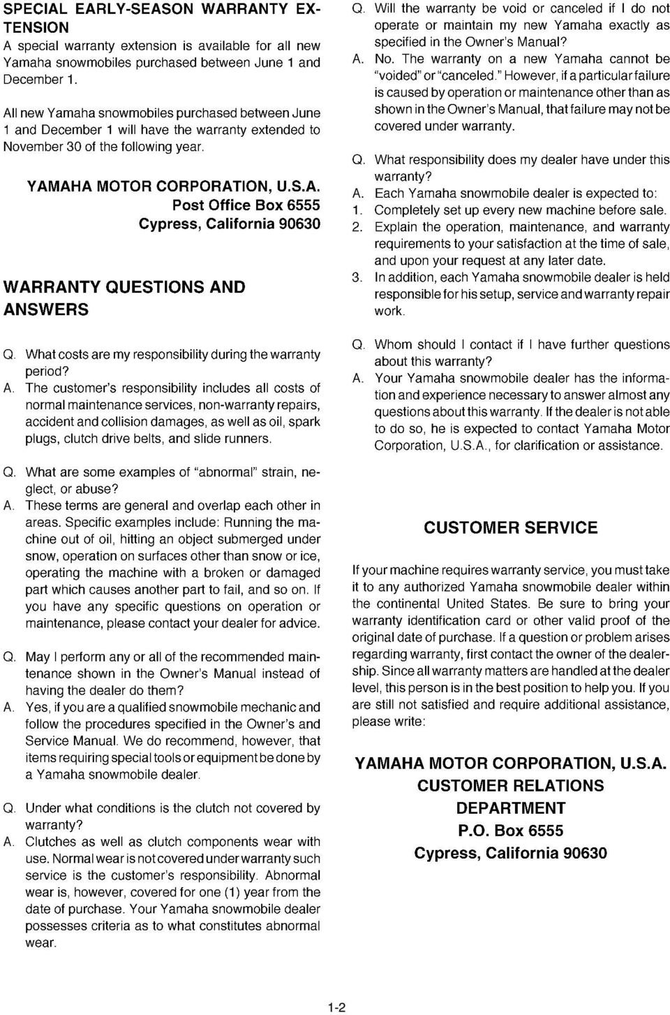
9 CW-02E 1-2
10 CW-03E 1-3

11 ESU00373 YAMAHA EXTENDED SERVICE (Y.E.S.) Keep your Yamaha protected even after your warranty expires with genuine Yamaha Extended Service (Y.E.S.). Y.E.S. is designed and administered by Yamaha Motor Corporation to provide maximum owner satisfaction. You get uninterrupted factory-backed coverage for extra peace of mind. Y.E.S. is flexible. You choose the plan that s right for you: 12 months, 24 months, 36 months, or (on the RX-1 only) even 48 months beyond your warranty period. Y.E.S. is designed and administered by the same Yamaha people who handle your warranty and it shows in the comprehensive coverage benefits. There are no mileage limitations. Coverage isn t limited to moving parts or the drive train like many so-called third party extended warranty programs. And Y.E.S. covers manufacturing defects just like the warranty. See the sample contract at your Yamaha dealer to see how comforting uninterrupted factory-backed protection can be. You don t have to pay anything for covered repairs. There s no deductible to pay, and repairs aren t pro-rated. You don t have any out-of pocket expenses for covered repairs. In addition, Travel and Recreation Interruption Protection (TRIP) is included at no extra cost. TRIP gives you up to $150 reimbursement per occurrence for any reasonable expenses you incur because your Yamaha needs covered service: replacement vehicle rental, emergency towing, phone calls, even food and lodging when you are away from home. This superb coverage goes into effect when you purchase Y.E.S., so it applies to any warranty repairs as well as covered repairs during your entire Y.E.S. plan period. Y.E.S. coverage is honored at any authorized Yamaha dealer nationwide. Y.E.S. coverage is transferable to a new owner if you sell or trade-in. That can make your Yamaha much more valuable! This excellent Y.E.S. plan coverage is only available to Yamaha owners like you, and only while your Yamaha is still within the Yamaha Limited Warranty period. So visit your authorized Yamaha dealer to get all the facts. He can show you how easy it is to protect your investment with Yamaha Extended Service. We urge you to act now. You ll get the excellent benefits of TRIP coverage right away, and you ll rest easy knowing you ll have strong factorybacked protection even after your Yamaha Limited Warranty expires. See your dealer today! A special note: If visiting your dealer isn t convenient, contact Yamaha toll free at (866 YES- EXTD) or visit our web site. All you need to do is provide your vehicle s Primary ID number (your Tunnel number). We ll be happy to help you get the Y.E.S. coverage you need. Yamaha Service Marketing P.O. Box 6555 Cypress, CA

12 ESU LOCATION OF THE IMPORTANT LABELS Please read the following labels carefully before operating this snowmobile. NOTE: Maintain or replace safety and instruction labels, as necessary. 1 RX10/RX10S/RX10M/RX10MS 1 RX10R/RX10RS

13 4 RX10M/RX10MS 5 RX10M/RX10MS 6 RX10M/RX10MS 2-2

14 ESU SAFETY INFORMATION When you ride your snowmobile, you must know and use the following for your safety. Severe injury or death may result if you ignore any of the following. Before operating 1. Read the Owner s Manual and all labels before operating this snowmobile. Become familiar with all of the operating controls and their function. Consult a Yamaha dealer about any control or function you do not understand. 2. This snowmobile was not manufactured for use on public streets, roads, or highways. Such use is prohibited by law, and you could collide with another vehicle. 3. This snowmobile is designed to carry the OPERA- TOR ONLY. Passengers are prohibited. Carrying a passenger can cause loss of control. 4. Do not operate the snowmobile after drinking alcohol or taking drugs. Your ability to operate the snowmobile is reduced by the influence of alcohol or drugs. 5. For safety and proper care of the snowmobile, always perform the pre-operation checks on pages before starting the engine. Check the throttle, brake, and steering for proper operation every time before starting the engine. Make sure that the throttle lever moves freely and it returns to the home position when it is released. 6. Apply the parking brake before starting the engine. Never drive the snowmobile with the parking brake applied. This may overheat the brake disc and reduce braking ability. 3-1

15 7. Do not allow anyone to stand behind the snowmobile when starting, inspecting, or adjusting the snowmobile. A broken track, track fittings, or debris thrown by the track could be dangerous to the operator or bystanders. 8. Handle fuel with care; it is HIGHLY FLAMMABLE. Never add fuel when the engine is running or hot. Allow the engine to cool for several minutes after running. Use an approved fuel container. Fill the fuel tank outdoors with extreme care. Never remove the fuel cap indoors. Never fill the fuel tank indoors. Never refuel while smoking or in the vicinity of an open flame. Make sure that the fuel tank cap is closed securely after refueling. Wipe up any spilled fuel immediately. 9. If you swallow some gasoline, inhale a lot of gasoline vapor, or get some gasoline into your eyes, see your doctor immediately. If any gasoline spills on your skin or clothing, immediately wash your skin with soap and water, and change your clothes. 10. Wear protective clothing. Wear an approved helmet, and a face shield or goggles. Also, wear a good quality snowmobile suit, boots, and a pair of gloves or mittens that will permit use of your thumbs and fingers for operation of the controls. Operation 1. Do not run the engine indoors, except when starting the engine to transport the snowmobile in or out of the building. Open the outside doors; exhaust fumes are dangerous. 2. Be careful where you ride. There may be obstacles hidden beneath the snow. Stay on established trails to minimize your exposure to hazards. Ride slowly and cautiously when you ride off of established trails. Hitting a rock or stump, or running into wires could cause an accident and injury. 3-2

16 3. This snowmobile is not designed for use on surfaces other than snow or ice. Use on dirt, sand, grass, rocks, or bare pavement may cause loss of control and may damage the snowmobile. 4. Avoid operating on glare ice, or on snow which has a lot of dirt or sand mixed in. Operation under such conditions will damage or result in rapid wear of ski runners, drive track, slide runners, and drive sprockets. 5. Always ride with other snowmobilers when going on a ride. You may need help if you run out of fuel, have an accident, or damage your snowmobile. 6. Many surfaces such as ice and hard-packed snow require much longer stopping distances. Be alert, plan ahead and begin decelerating early. The best braking method on most surfaces is to release the throttle and apply the brake gently not suddenly. Maintenance and storage 1. Do not leave the snowmobile on its left side for an extended period of time. Fuel may leak out from the fuel breather hose. 2. Modifications made to the snowmobile not approved by Yamaha, or the removal of original equipment may render your snowmobile unsafe for use that may cause severe personal injury. Modifications may also make the snowmobile illegal to use. 3. Never store the snowmobile with fuel in the fuel tank inside a building where ignition sources are present such as hot water and space heaters, an open flame, sparks, clothes dryers, and the like. Allow the engine to cool off before storing the snowmobile in an enclosed space. 4. Always refer to the STORAGE section if the snowmobile is to be stored for an extended period. 5. Maintain or replace safety and instruction labels, as necessary. 3-3

17 ESU DESCRIPTION 1 Windshield 2 Steering handlebar 3 Seat 4 Frame 5 Slide rail suspension 6 Drive track 7 Skis 8 Headlights 9 Shroud 0 Storage compartment RX10/RX10S/RX10R/RX10RS RX10M/RX10MS 4-1

18 4-2 A Tail/brake lights B Snow flap C Brake lever D Parking brake lever E Grip warmer adjustment switch F Headlight beam switch G Strap (RX10M/RX10MS) H Engine stop switch I Thumb warmer adjustment switch J Throttle lever K Shift lever (RX10R/RX10RS) L Shroud latch M Main switch N Starter lever O Tachometer P Low coolant temperature indicator light Q High beam indicator light R Warning light S Self-diagnosis warning indicator T Coolant temperature warning indicator U Fuel level warning indicator V Oil level warning indicator W Speedometer X Select/reset button Y Fuel meter and grip/thumb warmer heat level indicator Z Odometer/tripmeter

19 ESU CONTROL FUNCTIONS ESU00362 Main switch The main switch controls the following items. 1 OFF The ignition circuit is switched off. The key can be removed only in this position. 2 ON The ignition circuit is switched on. 3 START The starting circuit is switched on. The starter motor starts. CAUTION: Release the switch immediately after the engine starts. NOTE: The headlights, meter lights, and taillights come on after the engine starts. 5-1

20 ESU00020 Starter lever (choke) Use the starter lever (choke) when starting and warming up a cold engine. 1 Starter lever (choke) 2 When starting a cold engine. 3 Warming up 4 When the engine is warm. NOTE: Refer the Starting the engine section for proper operation. ESU00022 Throttle lever Once the engine is running cleanly, squeezing a the throttle lever 1 will increase the engine speed and cause engagement of the drive system. Regulate the speed of the snowmobile by varying the throttle position. Because the throttle is spring-loaded, the snowmobile will decelerate, and the engine will return to idle when it is released b. Check the throttle, brake, and steering for proper operation before starting the engine. ESU00361 Engine overheating prevention system This model is equipped with an engine overheating prevention system to prevent overheating when the engine is idling. When the engine has been idling for at least 3 minutes and the coolant temperature has risen above 100 C (212 F), the engine automatically shuts off to prevent overheating. NOTE: The engine can be started after it shuts off. 5-2

21 A ESU00023 Throttle override system (T.O.R.S.) If the carburetor or throttle cable should malfunction during operation, the T.O.R.S. will operate when the throttle lever is released. The T.O.R.S. is designed to interrupt the ignition and keep the engine revolution speed between 2,800 and 3,000 r/min if the carburetor fails to return to idle when the lever is released. If the T.O.R.S. is activated, make sure that the cause of the malfunction has been corrected and that the engine can be operated without a problem before restarting the engine. Be sure to use the specified spark plug and spark plug cap. Otherwise, the T.O.R.S. will not work properly. B CA-01E Mode A Idle B C or Run Trouble Switch starting Throttle switch Off On Off Carburetor switch On Off Off Engine Run Run T.O.R.S. will operate C È Idle or starting É Run Ê Trouble 1 Carburetor switch 2 Throttle switch 3 Throttle cable 4 Throttle valve a On b Off 5-3
22 ESU00339 Speedometer unit The speedometer unit is equipped with the following: a digital speedometer (which shows riding speed) an odometer (which shows the total distance traveled) a tripmeter (which shows the distance traveled since it was last set to zero) warning indicators (which show self-diagnosis, coolant temperature, fuel level, and oil level warnings) fuel meter (which shows the fuel remaining in the fuel tank) grip/thumb warmer heat level indicator (which shows the heat level of the grip warmer or the thumb warmer) After the engine is started, the tachometer 1 makes one sweep, and the warning light 2 and all segments of the meter 3 turn on and off once. Then the warning light turns on again, and then goes off if there are no problems. The grip warmer heat level is initially displayed for 5 seconds, then switches to the fuel meter display. Odometer and tripmeter modes Pushing the select/reset button 4 switches the display between the odometer mode ODO and the tripmeter mode TRIP. To reset the tripmeter, push the select/reset button for at least one second while the tripmeter is displayed. NOTE: To switch the speedometer, odometer, and tripmeter displays between kilometers and miles, select the odometer mode ODO, and then push the select/reset button 4 for at least 10 seconds. ESU00363 High beam indicator light The high beam indicator light 1 comes on when the high beams of the headlights are switched on. (See page 5-12 for headlight beam switch operation.) 5-4
23 ESU00340 Fuel meter and grip/thumb warmer heat level indicator The fuel meter and grip/thumb warmer heat level indicator has eight segments 1 which show the amount of fuel remaining in the fuel tank, the heat level of the grip warmer, or the heat level of the thumb warmer. Fuel meter As the fuel level decreases in the fuel tank, the segments disappear until the level goes down to the last segment E (Empty). When this occurs, the fuel level warning indicator 2 and the warning light 3 come on. If the fuel level warning indicator and the warning light come on, fill the fuel tank at the first opportunity. NOTE: The snowmobile must be stopped on a level surface to obtain an accurate fuel meter reading. The fuel meter reading changes as the snowmobile moves and depending on the inclination of the snowmobile. Grip/thumb warmer heat level indicator The grip warmer adjustment switch 1 and the thumb warmer adjustment switch 2 control the electrically heated handlebar grips and throttle lever. To raise the temperature, press each switch to HI. To lower the temperature, press each switch to LO. NOTE: The grip warmer heat level indicator 3 comes on and the display switches to the grip warmer heat level when the grip warmer adjustment switch is pressed. The thumb warmer heat level indicator 4 comes on and the display switches to the thumb warmer heat level when the thumb warmer adjustment switch is pressed. The grip/thumb warmer heat level is displayed for 5 seconds after releasing the grip/thumb warmer adjustment switch, then switches to the fuel meter. The top segment of the heat level indicator flashes if the grip/thumb warmer adjustment switches are continually pressed at the maximum level. The bottom segment of the heat level indicator flashes if the grip/ thumb warmer adjustment switches are continually pressed at the minimum level. Every time the engine is started, the grip/thumb heat levels return to the maximum levels. 5-5
24 ESU00287 Fuel level warning indicator The fuel level warning indicator indicates a malfunctioning sensor, disconnected coupler, broken lead, or short circuit when detected by the self-diagnosis device of the snowmobile. The fuel level warning indicator 1, warning light 2, and all segments of the fuel meter 3 warn the rider of the above problems by flashing continuously. (See the table below for warning indicator, warning light and fuel meter segment flash pattern.) When this occurs, have a Yamaha dealer inspect the snowmobile as soon as possible. CA-08E Warning indicator, warning light, and fuel meter segments of the fuel meter flash pattern s 3 s 0.5 s Warning indicator, warning light, and fuel meter segment flash continuously in this pattern. : On : Off s: Second ESU00377 Oil level warning indicator The oil level warning indicator 1 and the warning light 2 come on when the engine oil level is low. If the oil level warning indicator and the warning light come on, place the snowmobile on a level surface and allow it to idle for one minute. If the oil level warning indicator and the warning light go off, the engine oil level is sufficient, however it is getting low. Add engine oil as soon as possible. If the oil level warning indicator and the warning light do not go off, check the engine oil level in the oil tank (see page 6-3), and add engine oil if necessary. 5-6
25 ESU00360 Low coolant temperature indicator light The low coolant temperature indicator light 1 flashes when the coolant temperature is low and informs the rider that the snowmobile must be warmed up. After the engine is started, warm it up until the indicator light goes off. The snowmobile can be operated normally after the indicator light goes off. NOTE: When the low coolant temperature indicator light flashes, the engine control system prevents the engine speed from rising even if the throttle lever is pressed. ESU00364 Coolant temperature warning indicator If the engine overheats, the coolant temperature warning indicator 1 and the warning light 2 come on. When this occurs, stop the engine immediately and allow the engine to cool down, and then check the coolant level in the coolant reservoir. (See page 6-4.) CAUTION: Do not operate the engine if it overheats s 3 s 0.5 s The coolant temperature warning indicator indicates a malfunctioning sensor, disconnected coupler, broken lead, or short circuit when detected by the self-diagnosis device of the snowmobile. The coolant temperature warning indicator and warning light warn the rider of the above problems by flashing continuously. (See the table below for the warning light flash pattern.) When this occurs, have a Yamaha dealer inspect the snowmobile as soon as possible. CA-13E Warning light flash pattern Warning light flash continuously in this pattern. : On : Off s: Second 5-7
26 ESU00365 Self-diagnosis warning indicator The self-diagnosis warning indicator indicates a malfunctioning sensor, disconnected coupler, broken lead, etc., when detected by the self-diagnosis device of the snowmobile. The self-diagnosis warning indicator 1 and warning light 2 warn the rider of the above problems by flashing continuously. If necessary, ask a Yamaha dealer for further details. (See page 5-9 for warning indicator and warning light flash patterns.) If the self-diagnosis warning indicator and warning light flash continuously during operation, there may be some problem with the electrical circuit, lead couplers, etc. (See page 5-9 for warning indicator and warning light flash pattern numbers 1 6.) Stop the engine and allow it to cool off. Then, check that the wire harness couplers are connected properly in the engine compartment. If the self-diagnosis warning indicator and warning light flash after the engine has been started, note the flash pattern, and then have a Yamaha dealer inspect the snowmobile as soon as possible. 5-8
27 CA-14E No Self-diagnosis warning indicator and warning light flash patterns 0.75 s 2.5 s 0.75 s 0.25 s 4 s 0.75 s 0.25 s 3.5 s Warning indicator and warning light flash continuously in this pattern. Warning indicator and warning light flash continuously in this pattern. Warning indicator and warning light flash continuously in this pattern s 0.25 s 4.5 s Warning indicator and warning light flash continuously in this pattern s 0.25 s 5.5 s Warning indicator and warning light flash continuously in this pattern s 0.25 s 6.5 s Warning indicator and warning light flash continuously in this pattern. : On : Off s: Second 5-9
28 ESU00031 Engine stop switch The engine stop switch 1 is used to stop the engine in an emergency. Simply push 2 the stop switch to stop the engine. To start the engine, pull 3 the stop switch and proceed with starting the engine. (See page 7-1 for more details.) During the first few rides, practice using the stop switch so that you can react quickly in an emergency. ESU00033 Brake lever The snowmobile is stopped by braking the entire drive system. Squeeze the brake lever towards the handlebar grip to stop the snowmobile. 1 Brake lever 2 Brake lever end 3 Handlebar end NOTE: When the brake lever is operated, the brake light will illuminate. CAUTION: Make sure that the brake lever end does not project out over the handlebar end. This will help prevent brake lever damage when the snowmobile is placed on its side for service. The brake lever is equipped with a position adjuster. To adjust the brake lever position: 1. Loosen the locknut While lightly pushing the brake lever in direction a, finger tighten the adjusting bolt 2 to set the brake lever to the desired position. 3. Tighten the locknut securely after adjusting the brake lever. 5-10
29 A ESU00035 Parking brake lever When parking the snowmobile or starting the engine, apply the parking brake by moving the brake lever 1 to the left. To release the parking brake, move the parking brake lever 1 to the right. B È To apply the parking brake É To release the parking brake Always set the parking brake before attempting to start the engine. Never run the snowmobile with the parking brake applied. This may overheat the brake disc and reduce braking ability. ESU00341 Shift lever For RX10R/RX10RS The shift lever is used to put the snowmobile into forward or reverse. After coming to a complete stop, pull the shift lever out, slide it to FWD or to REV until it stops, and then release it. 1 Shift lever 2 Pull out 3 Slide to FWD (Forward) 4 Slide to REV (Reverse) 5 Release CAUTION: Do not shift from FWD to REV or from REV to FWD while the snowmobile is moving. Otherwise, the drive system could be damaged. 5-11
30 ESU00039 Headlight beam switch Push the headlight beam switch to change the headlight beam to high or low. 1 Headlight beam switch 2 Push 3 High beam 4 Low beam ESU00048 Shroud latches To open the shroud, unhook the shroud latches, and then slowly raise the shroud forward until it stops. When closing the shroud, slowly lower it to its home position, and then hook the shroud latches. 1 Shroud latch 2 Shroud CAUTION: Make sure that all cables and wires are in place when closing the shroud. Do not drive the snowmobile with the shroud open, unlatched, or removed. Keep your body and clothing away from rotating parts when servicing with the shroud open. Do not touch the hot muffler and engine during or immediately after operation. ESU00052 Drive guard The drive guard is designed to cover the V-belt clutch and V-belt in case parts break or come loose. Make sure that the drive guard is tightened securely before operating the snowmobile. Never run the engine with the V-belt or drive guard removed. 5-12
31 ESU00053 V-belt holders Keep a spare V-belt for emergency use by placing it into the V-belt holders provided. CAUTION: Make sure that the V-belt is installed securely in the holders. ESU00342 Storage compartment The storage compartment is located under the shroud. Open the storage compartment to store the tool kit, spare parts, or other small items. 5-13
32 ESU PRE-OPERATION CHECKS NOTE: Pre-operation checks should be made each time the snowmobile is used. The engine and muffler will be very hot after the engine has been run. Avoid touching the engine and muffler while they are still hot with any part of your body or clothing during inspection or repair. ESU00075 Fuel Make sure that there is sufficient fuel in the fuel tank. Recommended fuel: Unleaded gasoline Pump octane R+M ; 88 or higher 2 Fuel tank capacity: 38.0 L (8.4 Imp gal, 10.0 US gal) Fuel is HIGHLY FLAMMABLE and poisonous. Check the SAFETY INFORMATION section carefully before refueling. (See page 3-2.) Do not fill the fuel tank above the bottom of the filler tube 1. Fuel could overflow if the snowmobile is tilted on its side or if the ambient temperature rises, causing the fuel to warm up and expand. Make sure that the fuel tank cap is closed securely after refueling. Leaking fuel can catch fire. 2 Fuel level CAUTION: Oxygenated fuels (gasohol) containing a maximum 5% of ethanol can be used, although richer jetting may be required to prevent engine dam- 6-1
33 age. Consult a Yamaha dealer. Gasohol containing methanol is not recommended. Make sure that snow or ice does not enter the fuel tank when refueling. Do not use alcohol deicers or water absorbing additives with oxygenated fuel. The fuel tank should be filled with straight gasoline as specified. ESU00343 Engine oil Use a combination of the recommended SAE and API oil classifications shown in the chart below. CB-01E SAE F SAE 5W-30 API SE, SF, SG or higher C CAUTION: Use only 4-stroke engine oil. Engine oil also lubricates the starter clutch. In order to prevent clutch slippage, do not mix any chemical additives with the oil or use oils of a higher grade than CD. In addition, do not use oils labeled ENERGY CONSERVING II or higher. 6-2
34 ESU00344 Engine oil level The engine oil level should be checked before each use. CAUTION: Do not run the engine with too much or not enough oil in the oil tank. Oil could flow into the air filter case and the engine could be damaged. Checking the engine oil level 1. Place the snowmobile on a level surface and apply the parking brake. 2. Start the engine, warm it up for minutes, and then turn it off. 3. Disconnect the oil level gauge coupler 1. CAUTION: Disconnect the oil level gauge coupler before removing the oil level gauge/dipstick. Otherwise the cable can twist and become severed. 4. Remove the oil level gauge/dipstick 2, wipe it clean, insert it back into the filler hole (without screwing it in), and then remove it again to check the oil level. NOTE: The engine oil should be between the F 3 and E 4 level marks on the oil level gauge/dipstick. 5. If the engine oil is below the E level mark, add sufficient oil of the recommended type to raise it to the F level mark. (See page 6-2 for recommended oil.) CAUTION: When adding the engine oil, be careful not to fill above the F level mark on the oil level gauge/dipstick. Make sure that no foreign material enters the engine oil tank. 6. Insert the oil level gauge/dipstick into the oil filler hole, and then tighten it securely. 7. Connect the oil level gauge coupler. 6-3
35 ESU00086 Coolant Check the coolant level in the coolant reservoir when the engine is cold. If the coolant level is below the COLD LEVEL mark, add soft water until it reaches the COLD LEVEL mark. (See pages for more details.) 1 COLD LEVEL mark Do not remove the coolant reservoir cap when the engine is hot. CAUTION: Hard water or salt water is harmful to the engine parts. You may use boiled or distilled water, if soft water is not available. Tap water can be used temporarily in an emergency. 6-4
36 ESU00087 Throttle lever Check the throttle lever operation before starting the engine. The throttle lever must open smoothly and spring back to its home position when released. ESU00090 Throttle override system (T.O.R.S.) Check the T.O.R.S. for proper operation. When checking T.O.R.S.: Make sure that the parking brake is applied. Make sure that the throttle lever moves smoothly. Do not run the engine up to clutch engagement r/min. Otherwise, the snowmobile could start moving forward unexpectedly, which could cause an accident. 1. Start the engine. NOTE: Refer to the Starting the engine section. 2. Hold the pivot point of the throttle lever away from the throttle switch by putting your thumb (above) and forefinger (below) between the throttle lever pivot 1 and the engine stop switch housing 2. While holding the pivot point as described above, press the throttle lever 3 gradually. The T.O.R.S. will operate and the engine should run between 2,800 and 3,000 r/min. If the engine does not run between 2,800 and 3,000 r/min, stop the engine by turning the main switch to the OFF position and consult a Yamaha dealer. 6-5
37 ESU00091 Brake 1. Brake lever Test the brake at a low speed when starting out to make sure that it is working properly. If the brake does not provide proper braking performance, inspect the brake for wear or brake fluid leakage. (See pages for more details.) A soft, spongy feeling in the brake lever indicates a failure in the brake system. Do not operate the snowmobile if you find any problems in the brake system. You could lose braking ability, which could lead to an accident. Ask a Yamaha dealer to inspect and repair the brake system. CAUTION: Make sure that the brake lever end does not project out over the handlebar end. This is to prevent brake lever damage when the snowmobile is placed on its side. 2. Brake fluid Check the brake fluid level. (See page 8-20.) Add fluid if necessary. 1 Lower level Specified brake fluid: DOT 4 6-6
38 ESU00093 Brake fluid leakage Apply the brake for a few minutes. Check to see if any brake fluid leaks out from the brake hose joints or the master cylinder. If brake fluid leakage is found, ask a Yamaha dealer for immediate repairs. CAUTION: Brake fluid may deteriorate painted surfaces or plastic parts. Never spill any brake fluid. If any is spilled, clean it up immediately. ESU00094 V-belt Open the shroud and remove the drive guard. Check the V-belt for wear and damage. Replace if necessary. Wear limit a: 32.5 mm (1.28 in) Make sure that the drive guard is tightened securely before operating the snowmobile. Never run the engine without the V-belt or with the drive guard removed. ESU00096 Drive guard Check the drive guard mounts for damage. Make sure that the drive guard is firmly in place. 6-7
39 ESU00097 Drive track Check the drive track for deflection, wear, or damage. Adjust or replace if necessary. (See pages for more details.) Do not operate the snowmobile if you find damage to the drive track, or if it has been maladjusted. Drive track damage or failure could result in loss of braking ability and snowmobile control, which could cause an accident. ESU mm (2.0-in) high-profile pattern drive track For RX10M/RX10MS This snowmobile is originally equipped with a 51-mm (2.0-in) high-profile pattern drive track specifically for use in deep snow riding conditions. Therefore, avoid prolonged operation on hard surfaces such as ice, hard-packed snow, dirt, etc., to extend the life of the track and slide runners. CAUTION: Only use in deep snow riding conditions. Operation on areas with light snowfall, ice, hardpacked snow, dirt, or grass will result in rapid wear or damage to the track and slide runners from lack of snow which serves as a lubricant. ESU00098 Slide runners Check the slide runners for wear and damage. If the slide runners reach the wear limit, they should be replaced. 1 Slide runners a Wear limit Wear limit height: 10 mm (0.4 in) CAUTION: Ride on fresh snow frequently. Operating on ice or hard packed snow will rapidly wear the slide runners. 6-8
40 ESU00102 Skis and ski runners Check the skis and ski runners for wear and damage. Replace if necessary. Ski runner wear limit a: 8 mm (0.31 in) Ski wear limit b: 24 mm (0.95 in) CAUTION: Avoid scratching the skis when loading and unloading the snowmobile, when riding in areas with little or no snow, or on sharp edges such as concrete, curbs, etc. This will wear or damage the skis. ESU00103 Steering system Check the handlebar for excessive free play: 1. Push the handlebar up and down and back and forth. 2. Turn the handlebar slightly to the right and left. If excessive free play is noticed, consult a Yamaha dealer. ESU00378 Lights Check the lights. Replace any burned out bulbs. CAUTION: Avoid using a scraper or hot water for cleaning the plastic lenses
41 ESU00350 Air filter Always check that no snow is under the air filter element. Remove the air filter case cover and take out the air filter element. If there is any snow under the air filter element, remove the snow. Then install the air filter element beneath the holding guides on the case and install the air filter case cover. NOTE: After riding the snowmobile, make sure that there is no snow under the air filter element. ESU00110 Fittings and fasteners Check the tightness of the fittings and fasteners. Tighten in proper sequence and torque if necessary. ESU00345 Tool kit and recommended equipment It is good practice to carry the tool kit, spare parts, and other necessary equipment with you while riding the snowmobile so that minor repairs can be done if necessary. The following should be carried at all times: Tool kit Flashlight Roll of plastic tape Steel wire Towrope Jumper cables V-belt Light bulbs Spark plugs When you start out for a long distance trip, extra fuel and oil should be carried as well. 6-10
42 ESU OPERATION ESU00366 Starting the engine Be sure to check the SAFETY INFORMATION section carefully before starting the engine. Make sure that the parking brake is applied. NOTE: Make sure that the engine stop switch is in the on position. The starter motor cannot be operated when the engine stop switch is in the off position. 1. Fully open the starter lever (choke). 1 Starter lever (choke) 2 Fully open (cold engine starting) 3 Half-open (warm engine up) 4 Closed (warm engine starting) NOTE: The starter lever (choke) is not required when the engine is warm. Put the starter lever (choke) in the closed position. 2. Turn the main switch to the START position. After the engine starts, put the starter lever (choke) in the half-open position. Warm up the engine until it does not run roughly or begin to stall when the starter lever is returned to the closed position. 1 START CAUTION: Release the switch immediately after the engine starts. If the engine fails to start, release the switch, wait a few seconds, then try again. Each attempt should be as short as possible to preserve the battery. Do not crank the engine more than 10 seconds on any one attempt. 7-1
43 ESU00380 Break-in There is never a more important period in the life of your engine than the period between 0 and 500 km (300 mi). For this reason, you should read the following material carefully. Since the engine is brand new, do not put an excessive load on it for the first 500 km (300 mi). The various parts in the engine wear and polish themselves to the correct operating clearances. During this period, prolonged fullthrottle operation or any condition that might result in engine overheating must be avoided. Operating your snowmobile for the first time Start the engine and let it idle for 15 minutes km (0 100 mi) Avoid prolonged operation above 6,000 r/min km ( mi) Avoid prolonged operation above 8,000 r/min. 500 km (300 mi) and beyond The snowmobile can now be operated normally. CAUTION: After 800 km (500 mi) of operation, the engine oil must be changed and the oil filter cartridge replaced. If any engine trouble should occur during the engine break-in period, immediately have a Yamaha dealer check the snowmobile. 7-2
44 ESU00127 Riding your snowmobile totally familiar with the snowmobile s handling and performance characteristics. Getting to know your snowmobile A snowmobile is a rider active vehicle, and your riding position and your balance are the two basic factors of maneuvering your snowmobile. Riding your snowmobile requires skills acquired through practice over a period of time. Take the time to learn the basic techniques well before attempting more difficult maneuvers. Riding your new snowmobile can be a very enjoyable activity, providing you with hours of pleasure. However, it is essential to familiarize yourself with the operation of the snowmobile to achieve the skill necessary to enjoy riding safely. Before operating the snowmobile, read this Owner s Manual completely and understand the operation of the controls. Pay particular attention to the safety information on pages Please read all warning and caution labels on your snowmobile. Also, read the Snowmobiler s Safety Handbook that is supplied with your snowmobile. Learning to ride your snowmobile Before you ride, always perform the preoperation checks listed on pages The short time spent checking the condition of the snowmobile will be rewarded with added safety and a more reliable snowmobile. Always wear the proper clothing for both warmth and to help protect you from injury if an accident occurs. Become familiar with operating your snowmobile at low speeds, even if you are an experienced rider. Do not attempt to operate at maximum performance until you are Set the parking brake and follow the instructions on pages to start the engine. Once it has warmed up, you are ready to begin riding your snowmobile. To start out and accelerate 1. With the engine idling, release the parking brake. 2. Apply the throttle slowly and smoothly. The V-belt clutch will engage and you will start to accelerate. The operator should always keep both hands on the handlebar. Never put your feet outside the running boards. Avoid high speeds until you have become thoroughly familiar with your snowmobile and all of its controls. Braking When slowing down or stopping, release the throttle and apply the brake gently not suddenly. Many surfaces such as ice and hardpacked snow require much longer stopping distances. Be alert, plan ahead, and begin decelerating early. Improper use of the brake can cause the drive track to lose traction, reduce control, and increase the possibility of an accident. 7-3
45 Turning Riding uphill For most snow surfaces, body English is the key to turning. As you approach a curve, slow down and begin to turn the handlebar in the desired direction. As you do so, put your weight on the running board to the inside of the turn and lean your upper body into the turn. This procedure should be practiced at low speed many times, in a large flat area with no obstacles. Once you have learned this technique, you should be able to perform it at higher speeds or in tighter curves. Lean more as the turn gets sharper or is made at higher speeds. Improper riding procedures such as abrupt throttle changes, excessive braking, incorrect body movements, or too much speed for the sharpness of the turn may cause the snowmobile to tip. If your snowmobile begins to tip while turning, lean more into the turn to regain balance. If necessary, gradually let off on the throttle or steer to the outside of the turn. Remember: Avoid higher speeds until you are thoroughly familiar with the operation of your snowmobile. You should practice first on gentle slopes. Try more difficult climbs only after you have developed your skill. As you approach a hill, accelerate before you start the climb, and then reduce the throttle opening to prevent track slippage. It is also important to keep your weight on the uphill side at all times. On climbs straight up the hill this can be accomplished by leaning forward and, on steeper inclines, standing on the running boards and leaning forward over the handlebar. (Also see Traversing a slope. ) Slow down as you reach the crest of the hill, and be prepared to react to obstacles, sharp drops, or other vehicles or people which may be on the other side. If you are unable to continue up a hill, do not spin the track. Stop the engine and set the parking brake. Then pull the rear of the snowmobile around to point the snowmobile back down the hill. Do not get on the downhill side of the snowmobile. When the snowmobile is pointed downhill, restart the engine, release the parking brake, and descend the hill. Side hills and steep slopes are not recommended for a novice snowmobiler. 7-4
46 Riding downhill When riding downhill, keep speed to a minimum. It is important to apply just enough throttle to keep the clutch engaged while descending the hill. This will allow you to use engine compression to help slow the snowmobile, and to keep the snowmobile from rolling freely down the hill. Also apply the brake frequently, with light pressure. Use extra caution when applying the brake during a descent. Excessive braking will cause the drive track to lock, causing a loss of control. Traversing a slope Traversing slopes is not recommended for a novice snowmobiler. downhill leg on the seat and the foot of the uphill leg on the running board. This position will make it easier for you to shift your body weight as needed. Snow and ice are slippery, so be prepared for the possibility that your snowmobile could begin to slip sideways on the slope. If this happens, steer in the direction of the slide if there are no obstacles in your path. As you regain proper balance, gradually steer again in the direction you wish to travel. If your snowmobile starts to tip, steer down the hill to regain balance. If you are unable to maintain correct balance, and your snowmobile is going to tip over, dismount your snowmobile immediately on the uphill side. Ice or icy surface Operating on ice or icy surfaces can be very dangerous. Traction for turning, stopping, or starting is much less than that on snow. When you have to operate on ice or icy surfaces, drive slowly and cautiously. Avoid accelerating, turning, or braking rapidly. Steering is minimal and uncontrolled spins are an ever-present danger. Traversing a slope requires you to properly position your weight to maintain proper balance. As you travel across the slope, lean your body to position your weight towards the uphill side. A recommended riding position is to kneel with the knee of the 7-5
47 Hard-packed snow It can be more difficult to negotiate on hard-packed snow as both the skis and drive track do not have as much traction as when the snowmobile is operated on fresh snow. Avoid rapid acceleration, turning, or braking. Operation on surfaces other than snow or ice Operation of your snowmobile on surfaces other than snow or ice should be avoided. Operation under such conditions will damage or result in rapid wear of the ski runners, drive track, slide runners, and drive sprockets. Operation of the snowmobile under the following conditions should be avoided at all costs: 1. Dirt 2. Sand 3. Rocks 4. Grass 5. Bare pavement Other conditions that should be avoided for the sake of drive track and slide runner life are: 1. Glare ice surfaces 2. Snow mixed with a lot of dirt and sand All the above conditions have one thing in common in regard to drive track and slide runners; little or no lubricating ability. Drive track and all slide rail systems require lubrication (snow or water) between the slide runners and the slide metal. In the absence of lubrication, the slide runners will rapidly wear and in severe cases, literally melt away, and the drive track will be subjected to damage or failure. Also traction aids such as studs, cleats, etc., may cause further track damage or failure. Drive track damage or failure could result in loss of braking ability and snowmobile control, which could cause an accident. Always check the drive track for damage or maladjustment before operating the snowmobile. Do not operate the snowmobile if you find damage to the drive track. CAUTION: Ride on fresh snow frequently. Operating on ice or hard-packed snow will rapidly wear the slide runners. 7-6
48 ESU00251 Maximizing drive track life Recommendations Track tension During initial break-in, the new drive track will tend to stretch quickly as the track settles. Be sure to correct the track tension and alignment frequently. (See pages for adjustment procedures.) A loose track can slip (ratchet), derail or catch on suspension parts causing severe damage. Do not overtighten the drive track, otherwise it may increase the friction between the track and the slide runners, resulting in the rapid wear of both components. Also, this may put an excessive load on the suspension components, resulting in component failure. Marginal snow The drive track and the slide runners are lubricated and cooled by snow and water. To prevent the drive track and slide runners from overheating, avoid sustained highspeed usage in areas such as icy trails, frozen lakes and rivers that have minimal snow coverage. An overheated track will be weakened internally, which may cause failure or damage. Off-trail riding Avoid off-trail riding until there is sufficient snow coverage. It generally takes several feet of snow to provide a good overall base to properly cover debris, such as rocks, logs, etc. If snow coverage is not sufficient, stay on trails to avoid impact damage to the drive track. Studded track In general, track life will be shortened when studs are installed. Drilling stud holes into the drive track will cut the internal fibers, which weakens the track. Avoid spinning the drive track. Studs may catch on an object and pull out of the track, leaving tears and damage around the already weakened area. To minimize possible damage, consult your stud manufacturer for installation and stud pattern recommendations. Yamaha does not recommend track studding. 7-7
YFM400FV OWNER S MANUAL WARNING. READ THIS MANUAL CAREFULLY! It contains important safety information.
 READ THIS MANUAL CAREFULLY! It contains important safety information. OWNER S MANUAL WARNING LIT-11626-19-08 YFM400FV This ATV should not be ridden by anyone under 16 years of age. 5FU-F8199-16 EBU00776
3620 W 11th Streetб Houston, TX 77008 Telephone: 713-635-6291 Email: sales@kellogg-american.com Website: www.kellogg-american.com
 Unpackaging & Handling Be sure to carefully inspect the unit before accepting the shipment. If any damage has occurred document it with the trucking company immediately. Contact your Kellogg Distributor
Sport Ice Elektro 124
 Sport Ice Elektro 124 Operation Manual 2007/4 V2.1 Introduction The Sport Ice Elektro 124 is an ice resurfacing machine designed to be used on small ice surfaces. The machine has been designed to produce
YFM25RX OWNER S MANUAL LIT-11626-21-22 4D3-28199-10 WARNING. READ THIS MANUAL CAREFULLY! It contains important safety information.
 READ THIS MANUAL CAREFULLY! It contains important safety information. OWNER S MANUAL WARNING LIT--- YFMRX This ATV A should not be ridden by anyone under years of age. D-- EBU EBU INTRODUCTION EBU0 Congratulations
INSPECTION BEFORE RIDING
 INSPECTION BEFORE RIDING Check the following items before riding. ITEM Engine cum transmission oil Fuel Tyres Battery Speedometer Lighting Steering Throttle Clutch Brakes Wheels WHAT TO CHECK FOR Availability
MODEL T-4 TRENCHER. Operators Manual
 DO NOT THROW AWAY IMPORTANT MANUAL MODEL TRENCHER Operators Manual P.O.BOX 290 San Bernardino, CA. 92402 Phone (909) 478-5700 (800) 922-4680 Fax (909) 478-5710 E-mail: sales@groundhoginc.com www.groundhoginc.com
READ THIS MANUAL CAREFULLY! It contains important safety information. OWNER S MANUAL YXR660FAT
 READ THIS MANUAL CAREFULLY! It contains important safety information. OWNER S MANUAL LIT-11626-18-46 YXR660FAT 5UG-F8199-11 EVU00010 1ĪNTRODUCTION Congratulations on your purchase of the Yamaha YXR660FA.
Read this manual carefully before operating this vehicle. OWNER S MANUAL YN50FU 5C3-F8199-E2
 Read this manual carefully before operating this vehicle. OWNER S MANUAL YN50FU 5C3-F8199-E2 Read this manual carefully before operating this vehicle. This manual should stay with this vehicle if it is
GENERAL KNOWLEDGE PRACTICE TEST
 GENERAL KNOWLEDGE PRACTICE TEST 1. Driving under the influence of any drug that makes you drive unsafely is: a. Permitted if it is prescribed by a doctor b. Against the law c. Permitted if it is a diet
15GAL STEEL OIL DRAIN WITH 110V PUMP
 15GAL STEEL OIL DRAIN WITH 110V PUMP OWNER S MANUAL WARNING: Read carefully and understand all ASSEMBLY AND OPERATION INSTRUCTIONS before operating. Failure to follow the safety rules and other basic safety
TABLE OF CONTENTS. Section 1 - Assembling your new pit bike.
 Orion Pit Bike Sales Owners Manual (All information and content is the property of Orion Pit Bike Sales. Any attempt to copy or resell is a direct violation of our copyright. All violators will be prosecuted)
This manual should be considered a permanent part of the motorcycle and should remain with the motorcycle when it is resold.
 This manual should be considered a permanent part of the motorcycle and should remain with the motorcycle when it is resold. This Owner s Manual covers the CBR600RR and CBR600RR ABS models. You may find
2009 QUICK REFERENCE GUIDE GET INFORMED. ROLL.
 xb 2009 QUICK REFERENCE GUIDE GET INFORMED. ROLL. 2009 Scion xb This Quick Reference Guide is a summary of basic vehicle operations. It contains brief descriptions of fundamental operations so you can
No part of this publication may be reproduced without written permission.
 This manual should be considered a permanent part of the motorcycle and should remain with the motorcycle when it is resold. This publication includes the latest production information available before
OWNER S MANUAL YP400X
 OWNER S MANUAL LIT--- YP00X RU-- EAU00 INTRODUCTION EAU000 Congratulations on your purchase of the Yamaha YP00X. This model is the result of Yamaha s vast experience in the production of fine sporting,
Failure to comply with the following cautions and warnings could cause equipment damage and personal injury.
 1.0 IMPORTANT RECEIVING INSTRUCTIONS Visually inspect all components for shipping damage. Shipping Damage is not covered by warranty. If shipping damage is found, notify carrier at once. The carrier is
CHROME FRONT BRAKE MASTER CYLINDER KIT
 -J075 REV. 009-0-0 CHROME FRONT BRAKE MASTER CYLINDER KIT GENERAL Kit Number 5-99D, 5-99D Models These Chrome Master Cylinder Kits are designed to replace the original equipment front brake master cylinder
ZAPPY 3 OWNER S MANUAL. Read this manual completely before riding your Electric ZAPPY 3.
 ZAPPY 3 OWNER S MANUAL Read this manual completely before riding your Electric ZAPPY 3. TECHNICAL INFORMATION Model No. : ZAPPY 3 Product size Type of motor Motor power Battery type Battery Charger Charging
OPERATOR'S MANUAL i-shift transmission
 OPERATOR'S MANUAL i-shift transmission R Volvo Trucks. Driving Success. Table of Contents i Foreword... 1 Safety Information... 2 Volvo I-Shift Transmission... 4 General Information... 4 Gear Selector...
general, accidents caused by misjudging
 Unit 3: The Effect of Natural Forces on your Vehicle Page 1 of 11 Purpose: Acquaint the student with some of the natural forces acting on a vehicle while stopping, maneuvering, and during a crash. Explain
HYDRAULIC TABLE CART 500-LB.
 HYDRAULIC TABLE CART 500-LB. OWNER S MANUAL WARNING: Read carefully and understand all MACHINE ADJUSTMENT AND OPERATION INSTRUCTIONS before operating. Failure to follow the safety rules and other basic
GNOME PELLET E.I. Pellet Heater Owner's Manual Installation and Operating Instructions. Please read this entire manual before installation.
 Pellet Heater Owner's Manual Installation and Operating Instructions Please read this entire manual before installation. Save these instructions. SAFETY NOTICE HEATER MUST BE PROPERLY INSTALLED AND MAINTAINED
IMPORTANT SAFETY INSTRUCTIONS WARNING READ AND SAVE THESE OPERATING AND SAFETY INSTRUCTIONS BEFORE USING THIS HEATER.
 THERMAWAVE CERAMIC HEATER Model HZ-850 Series Model HZ-860 Series IMPORTANT SAFETY INSTRUCTIONS WARNING READ AND SAVE THESE OPERATING AND SAFETY INSTRUCTIONS BEFORE USING THIS HEATER. Warning Failure to
Table of Contents. Introducing AYGO. Accessing your vehicle 2 3. Lights 9. Wipers 10. Electric windows 4. Gear change 11
 AYGO Brief Guide Table of Contents Accessing your vehicle 2 3 Electric windows 4 Steering wheel (Vehicles with an adjustable type) 4 Seat and seat belt adjustment 5 Instrument Panel overview 6 Instrument
Solstice/Sky Water Pump Replacement
 Solstice/Sky Water Pump Replacement The water pump on the Solstice/Sky is starting to need replacement on some vehicles. This guide will help in replacing the water pump while the engine is still in the
Installation Instructions for Alarm Module Kit A043F059
 Instruction Sheet 07-2013 Installation Instructions for Alarm Module Kit A043F059 1 Introduction The information contained within is based on information available at the time of going to print. In line
Videos for Safety Meetings
 Videos for Safety Meetings 2474 2005, ERI Safety Videos OPERATING ELECTRIC PALLET JACKS SAFELY This easy-to-use Leader s Guide is provided to assist in conducting a successful presentation. Featured are:
Not required for most applications Not required for most applications High pressure (12-803 provided) High pressure (12-803 provided)
 High pressure (12-803 provided)") ELECTRIC FUEL PUMPS P/N 12-801-1, 712-801-1, 12-802-1, 712-802-1, 12-815-1, & 712-815-1 FUEL PRESSURE REGULATORS P/N 12-803, 12-501, 12-804, 12-500, & 15812NOS Installation Instructions THESE INSTRUCTIONS
ELECTRIC FUEL PUMPS P/N 12-801-1, 712-801-1, 12-802-1, 712-802-1, 12-815-1, & 712-815-1 FUEL PRESSURE REGULATORS P/N 12-803, 12-501, 12-804, 12-500, & 15812NOS Installation Instructions THESE INSTRUCTIONS
Conservation of Momentum Greg Kifer
 SCIENCE EXPERIMENTS ON FILE Revised Edition 6.7-1 Conservation of Momentum Greg Kifer Topic Conservation of momentum Time 1 hour! Safety Please click on the safety icon to view the safety precautions.
Thailand Motorcycle Safety Course
 Thailand Motorcycle Safety Course Lesson 3 Getting Ready to Ride PREPARING TO RIDE What you do before you start a trip goes a long way toward determining whether or not you ll get where you want to go
REPAIR ONLY. NO REFUND!
 OPERATING MANUAL REPAIR ONLY. NO REFUND! (Warning Symbol) WARNINGS: THIS IS NOT A TOY. PLEASE USE RESPONSIBLY MAXIMUM WEIGHT LIMIT - 70KG RECOMMENDED MINIMUM AGE LIMIT 12 YEARS PARENTAL SUPERVISION IS
IMPORTANT INSTRUCTIONS & OPERATING MANUAL. Houston 50 Inch Electric Wall Mounted Fireplace Black / White
 IMPORTANT INSTRUCTIONS & OPERATING MANUAL Houston 50 Inch Electric Wall Mounted Fireplace Black / White Model Number:MFE5050BK Model Number:MFE5050WH Read these instructions carefully before attempting
SECURITY SYSTEM SMART SIREN KIT
 -J00876 REV. 009-0-09 SECURITY SYSTEM SMART SIREN KIT GENERAL Kit Number 688-0 Models For model fitment information, see the P&A Retail Catalog or the Parts and Accessories section of www.harley-davidson.com
Safety Rules. Car Washes CORPORATE HEADQUARTERS 518 EAST BROAD STREET COLUMBUS, OHIO 43215 614.464.5000 STATEAUTO.COM
 TM Safety Rules Car Washes CORPORATE HEADQUARTERS 518 EAST BROAD STREET COLUMBUS, OHIO 43215 614.464.5000 STATEAUTO.COM TM Disclaimer: The information contained in this publication was obtained from sources
UNITED STATES AND U.S. TERRITORIES AND POSSESSIONS EXCEPT PUERTO RICO 2016 / WARRANTY & MAINTENANCE MANUAL
 UNITED STATES AND U.S. TERRITORIES AND POSSESSIONS ECEPT PUERTO RICO 2016 / WARRANTY & MAINTENANCE MANUAL Maintenance Service precautions Vehicle maintenance is an important yet frequently neglected item.
Powered Industrial Truck Safety Program
 Powered Industrial Truck Safety Program TABLE OF CONTENTS Forklift Safety Program 1.0 Overview... 3 2.0 Policy.....3 3.0 Requirements 3 4.0 Purpose. 3 5.0 Scope......4 6.0 Forklift Procedures 4 6.0 Responsibilities.....6
LIFT N RACK PRO OPERATING & INSTALLATION GUIDE 5500 Lb. LIFT CAPACITY
 LIFT N RACK PRO OPERATING & INSTALLATION GUIDE 5500 Lb. LIFT CAPACITY IMPORTANT: READ THIS MANUAL BEFORE IN-STALLING, OPERATING OR MAINTAINING YOUR LIFT. Chassis Liner Company Sales Office Toll Free: 800-242-2448
Multi-information Display (see MID )
") Driving Position Memory (see Seats ) Power Mirrors (see Mirrors ) Indicators/Gauges (see Instrument Panel ) Multi-information Display (see MID ) HomeLink (see HomeLink ) Navigation System (see Navigation
Driving Position Memory (see Seats ) Power Mirrors (see Mirrors ) Indicators/Gauges (see Instrument Panel ) Multi-information Display (see MID ) HomeLink (see HomeLink ) Navigation System (see Navigation
WARNING! WARNING! ENGLISH 18 ENGLISH
 SKELETON RAKES Carefully read, follow and understand the instructions given in this manual. It is an essential part of the product, and you should keep it in a safe place for future reference. MECHANIC
INSTALLATION INSTRUCTIONS MULTI-MOUNT KIT Part Number: 75330 Application: Warn HP PowerPlant P/N 71800
 INSTALLATION INSTRUCTIONS MULTI-MOUNT KIT Part Number: 75330 Application: Warn HP PowerPlant P/N 71800 Your safety, and the safety of others, is very important. To help you make informed decisions about
Quick Start Guide See Inside for Use and Safety Information
 3 rd Generation Personal 3D Printer Quick Start Guide See Inside for Use and Safety Information The USB Mass Storage Device Contains the User Guide and Quick Start Guide in other Languages Congratulations
BUSINESS REPLY MAIL. P.O. Box 47700 Hamel, MN 55340-9960 USA. Attn: Warranty Dept NO POSTAGE NECESSARY IF MAILED IN THE UNITED STATES
 NO POSTAGE NECESSARY IF MAILED IN THE UNITED STATES BUSINESS REPLY MAIL FIRST CLASS PERMIT NO. 21907 MINNEAPOLIS, MINNESOTA POSTAGE WILL BE PAID BY ADDRESSEE P.O. Box 47700 Hamel, MN 55340-9960 USA Attn:
MODEL G300 BRAKE BLEEDER
 MODEL G300 BRAKE BLEEDER Installation, Operation & Repair Parts Information Branick Industries, Inc. 4245 Main Avenue P.O. Box 1937 Fargo, North Dakota 58103 REV060616 P/N: 81-0035G 1 THIS PAGE INTENTIONALLY
Mini Pallet Jack OWNER S MANUAL
 Mini Pallet Jack OWNER S MANUAL WARNING: Read carefully and understand all ASSEMBLY AND OPERATION INSTRUCTIONS before operating. Failure to follow the safety rules and other basic safety precautions may
FJ2. 2 Ton Trolley Floor Jack Assembly & Operating Instructions
 FJ2 2 Ton Trolley Floor Jack Assembly & Operating Instructions READ ALL INSTRUCTIONS AND WARNINGS BEFORE USING THIS PRODUCT. This manual provides important information on proper operation & maintenance.
Portable Air Conditioner
 Portable Air Conditioner Owner's Manual Model:3 in 1 12,000 Btu/h Series 3 Please read this owner s manual carefully before operation and retain it for future reference. CONTENTS 1. SUMMARY...1 2. PORTABLE
Class 5 to 7 Truck and Bus Hydraulic Brake System
 Class 5 to 7 Truck and Bus Hydraulic Brake System Diagnostic Guide 1st Edition * 5+0 Important Service tes The information in this publication was current at the time of printing. The information presented
Tank Touring Deluxe Scooter 150cc 4 Stroke. Operating and Maintenance Manual
 Tank Touring Deluxe Scooter 150cc 4 Stroke Operating and Maintenance Manual Contents Save Driving Regulations 1 Parking 19 Driving Tips 2 Inspection & Servicing 21 Loading 3 Fuel 21 Features and Controls
18SP653* EPA04 and EPA98 MBE 4000 High Pressure Fuel Line and Transfer Tube Installation
 18SP653* EPA04 and EPA98 MBE 4000 High Pressure Fuel Line and Transfer Tube Installation * - Rev. 9/24/08 KIT DESCRIPTION A service kit (P/N: A4600700135) is now available to install EPA07 high pressure
Dehumidifier Users manual. For Models: DH45S DH65S
 Dehumidifier Users manual For Models: DH45S DH65S 950-0062-revD Jan. 9 2007 FORWARD The appearance of the units that you purchase might be slightly different from the ones described in the Manual, but
SV710-SV740. SV810-SV840 Owner's Manual
 SV710-SV740 SV810-SV840 Owner's Manual IMPORTANT: Read all safety precautions and instructions carefully before operating equipment. Refer to operating instruction of equipment that this engine powers.
orlando OWNER S MANUAL
 orlando OWNER S MANUAL 2 Assembling & operating manual Orlando 30 mbar - PORTABLE GAS BARBECUE 1. 2. 3. Improper installation, adjustment, alteration, service or maintenance can injury or property damage.
CDS TROUBLESHOOTING SECTION I. VACUUM. 1.0. Weak vacuum at wand. Gauge reads normal (10hg to 14hg)
") CDS TROUBLESHOOTING SECTION I. VACUUM 1.0. Weak vacuum at wand. Gauge reads normal (10hg to 14hg) 1.1. Clogged hoses or wand tube. Disconnect hoses and carefully check for an obstruction. 1.2. Excessive
CDS TROUBLESHOOTING SECTION I. VACUUM 1.0. Weak vacuum at wand. Gauge reads normal (10hg to 14hg) 1.1. Clogged hoses or wand tube. Disconnect hoses and carefully check for an obstruction. 1.2. Excessive
Owner s Manual Read and keep this manual. Patents World Wide
 Owner s Manual Read and keep this manual. Patents World Wide S & S Industries, Inc., Sarasota, FL, USA www.trail-gator.com Copyright 2008 All Rights Reserved The following manual is provided to assist
356 CHECKLIST ELECTRICAL: CHASSIS:
 356 CHECKLIST ELECTRICAL: Headlights hi/lo beam Taillights Running lights Turn signals Brake lights License light(s) Fog lights Reverse light Horn Dome lights Dash lights Temp guage Tank level guage Tachometer
Refrigerant Charging Unit ICOGD. 020AH1000 Operating Manual. FR.8.2.4-09 İ-COLD 12.03.2014 Rev. 00
 E Refrigerant Charging Unit ICOGD 020AH1000 Operating Manual FR.8.2.4-09 İ-COLD 12.03.2014 Rev. 00 Contents Technical Specifications... 20 Safety... 21 A/C System... 22 Components... 23 Control Panel...
Instruction Manual. Image of SP-3015 & SP-3815. Important Safeguards. Automatic Dispensing Hot Water Pot with Reboil Function
 Important Safeguards READ ALL INSTRUCTIONS BEFORE USE. Instruction Manual Automatic Dispensing Hot Water Pot with Reboil Function Image of SP-3015 & SP-3815 SP-3015: 3.0L SP-3815: 3.8L SP-3017: 3.0L (Stainless
DANGER DANGER. General Information. Safety Is Your Responsibility. Ordering Parts. Contact Information
 Safety Safety Is Your Responsibility DANGER To avoid personal injury or death, carefully read and understand all instructions pertaining to the Anthony Liftgates product. Do not attempt to install, operate,
Operator s Manual. PUMP Model: PAC25 SAVE THIS MANUAL FOR FUTURE REFERENCE. Distributed by: Pacer Pumps
 Operator s Manual PUMP Model: PAC25 CAUTION: Before using this product, read this manual and follow all Safety Rules and Operating Instructions. SAVE THIS MANUAL FOR FUTURE REFERENCE Distributed by: Pacer
IMPORTANT SAFETY RULES TO FOLLOW
 WARNING FLOOR & CARPET CLEANER Any piece of equipment can be dangerous if not operated properly. YOU are responsible for the safe operation of this equipment. The operator must carefully read and follow
You're reading an excerpt. Click here to read official BH FITNESS T1 BASIC user guide http://yourpdfguides.com/dref/2696507
 You can read the recommendations in the user guide, the technical guide or the installation guide for BH FITNESS T1 BASIC. You'll find the answers to all your questions on the BH FITNESS T1 BASIC in the
AKRAPOVIC SLIP-ON EXHAUST SYSTEM for the HONDA CB1000R
 Installation instructions: *502131* AKRAPOVIC SLIP-ON EXHAUST SYSTEM for the HONDA CB1000R Congratulations on purchasing an Akrapovic exhaust system. Please read these installation instructions carefully.
BUGGY SETUP GUIDE. Volume GOKARTSUSA GY6 150, CN250. Buggy Setup Guide
 BUGGY SETUP GUIDE Volume 1 GOKARTSUSA GY6 150, CN250 Buggy Setup Guide GY6 150, CN250 DUNE BUGGY Buggy Setup Guide GOKARTSUSA.COM 2000 Highway 50 S. Lake Tahoe, CA 96150 Phone 800.603.1437 2 Table of Contents
TOYOTA ELECTRONIC TRANSMISSION CHECKS & DIAGNOSIS
 Checks and Adjustments The transmission requires regular maintenance intervals if it is to continue to operate without failure. As we discussed in previous sections, transmission fluid loses certain properties
bizobike Quality Folding Bikes Instruction manual
 bizobike Quality Folding Bikes Instruction manual 01. Saddle 02. Seatpost 03. Stem 04. Handlebar 05. Front Fork 06. Brake 07. Wheel 20 08. Frame 09. Crank set 10. Chain 11. Rear derailleur 12. Seatpost
STEERING HANDLEBAR/FRONT WHEEL/ FRONT SHOCK ABSORBER
 14 14 STEERING HANDLEBAR/FRONT WHEEL/ SCHEMATIC DRAWING ------------------------------------------------- 14-1 SERVICE INFORMATION------------------------------------------------ 14-2 TROUBLESHOOTING-----------------------------------------------------
SBC90. Abrasive Blast Cabinet Assembly & Operating Instructions
 SBC90 Abrasive Blast Cabinet Assembly & Operating Instructions READ ALL INSTRUCTIONS AND WARNINGS BEFORE USING THIS PRODUCT. SAVE THESE INSTRUCTIONS FOR FUTURE REFERENCE. This manual provides important
TECHNICAL BULLETIN. Meritor WABCO Cab Leveling Valves and Chassis Leveling Valves. How the Cab Leveling and Chassis Leveling Valves Work
 Revised 02-00 TECHNICAL BULLETIN Meritor WABCO Cab Leveling Valves and Chassis Leveling Valves This technical bulletin covers both cab and chassis leveling valves manufactured by Meritor WABCO. While the
1. When the roads are slippery, you should make turns as gentle as possible.
 GENERAL KNOWLEDGE KEY FACTS CDL 1. When the roads are slippery, you should make turns as gentle as possible. 2. The heavier a vehicle or the faster it is moving, the more heat the brakes have to absorb
3053 Electrical Safety Training Program Course Outline
 3053 Electrical Safety Training Program Course Outline The following outline summarizes the major points of information presented in the program. The outline can be used to review the program before conducting
SALEEN SPEEDLAB SERIES VI STANDARD SC UPGRADE KIT
 SALEEN SPEEDLAB SERIES VI STANDARD SC UPGRADE KIT INSTALLATION MANUAL: 2005 MUSTANG 4.6 3V MANUAL P/N: 10-8002-C14338C SUPERCHARGER KIT P/N: 10-1607-B14083* Saleen Performance, Inc. 1225 East Maple Rd.,
Trouble Shooting. Pump
 Trouble Shooting Pump Trouble Possible Cause Remedy Oil leaking in the area of water pump crankshaft Worn crankshaft seal, bad bearing, grooved shaft, or failure of retainer o-ring. Excessive play on crankshaft
Service Packages & Pricing
 Service Packages & Pricing Silver Gold Motorcycle Service Packages Change oil & filter Change oil & filter Fuel system treatment $ 109.95 $ 129.95 Platinum Replace spark plugs Change oil & filter Fuel
COOLING SYSTEM Section Page
 5 COOLING SYSTEM Section Page 5.1 COOLANT PRE-HEATER... 5-3 5.2 COOLANT PUMP NON-EGR ENGINE... 5-7 5.3 COOLANT PUMP EGR ENGINE... 5-13 5.4 FRONT CONNECTOR HOUSING NON-EGR ENGINE... 5-17 5.5 FRONT CONNECTOR
Cable Drum Machine. Operation Manual BC260 SERIES. Cleans 1 1/4" to 3" lines up to 50'
 Cable Drum Machine Operation Manual BC260 SERIES Cleans 1 1/4" to 3" lines up to 50' Used For: Sink, Shower & Floor Drains 42FM " WARNING - Read All Instructions, When Using Electric Tools, Basic Safety
UDOT RPMS VEHICLE RECORDS, PREVENTIVE MAINTENANCE & SURVEILLANCE
 UDOT RPMS VEHICLE RECORDS, PREVENTIVE MAINTENANCE & SURVEILLANCE VEHICLE RECORDS AND PREVENTIVE MAINTENANCE Prepared by: UTAH DEPARTMENT OF TRANSPORTATION OFFICE OF PLANNING AND PROGRAMMING IN COOPERATION
Failure to comply with the following cautions and warnings could cause equipment damage and personal injury.
 1.0 IMPORTANT RECEIVING INSTRUCTIONS Visually inspect all components for shipping damage. Shipping Damage is not covered by warranty. If shipping damage is found, notify carrier at once. The carrier is
BATHROOM HEATER. User's Manual. Page 2...A515 Page 9...A716
 BATHROOM HEATER User's Manual Page 2...A515 Page 9...A716 BATHROOM HEATER User's Manual A515 SAVE THESE INSTRUCTIONS AND READ ALL INSTRUCTIONS BEFORE USING THE HEATER. Dear customers, Thank you for selecting
VALACH MOTORS s.r.o. VM R7-800/R5-420 OWNER S INSTRUCTION MANUAL
 VALACH MOTORS s.r.o. VM R7-800/R5-420 OWNER S INSTRUCTION MANUAL It is of vital importance, before attempting to operate your engine, to read the general 'SAFETY INSTRUCTIONS AND WARNINGS' section on pages
USER MANUAL WARNING! CONTENTS MODEL 1 SPECIFICATIONS READ ALL INSTRUCTIONS BEFORE PROCEEDING. Non-Programmable Single Stage Heat/Cool Thermostat
 Builder MODEL 1010 Series Non-Programmable Single Stage Heat/Cool Thermostat USER MANUAL Compatible with low voltage single stage gas, oil or electric heating or cooling systems, including single stage
HYDRAULIC LIFT TABLE CART 2200-LB.
 HYDRAULIC LIFT TABLE CART 2200-LB. OWNER S MANUAL WARNING: Read carefully and understand all MACHINE ADJUSTMENT AND OPERATION INSTRUCTIONS before operating. Failure to follow the safety rules and other
REMOVAL AND INSTALLATION
 303-01C-1 REMOVAL AND INSTALLATION Engine Body On Special Tool(s) Adapter For 303-D043 303-D043-02 or equivalent Special Tool(s) 303-01C-1 Turbocharger Lifting Bracket 303-1266 Wrench, Fan Clutch Nut 303-214
FOR THE FOLLOWING MODELS: EE-8075W EE-8075O EE-8075R EE-8075BK
 FIREPLACE HEATER FOR THE FOLLOWING MODELS: EE-8075W EE-8075O EE-8075R EE-8075BK If you have any questions about the operation of your fireplace heater, please contact Crane Customer Care. Toll Free: 888-599-0992
Carpet Washer. vax.co.uk VRS5W. Vax Careline: (UK) 0844 412 8455 (ROI) 1-800 928 308. Vax model number: Version 1.0
 0844 412 8455 (ROI) 1-800 928 308. Vax model number: Version 1.0") VRS5W Powermax User Guide V1.0.qxd:V1.0 23/7/10 15:35 Page 1 Vax Careline: (UK) 0844 412 8455 (ROI) 1-800 928 308 Carpet Washer Vax model number: VRS5W instruction manual Version 1.0 Please read carefully
VRS5W Powermax User Guide V1.0.qxd:V1.0 23/7/10 15:35 Page 1 Vax Careline: (UK) 0844 412 8455 (ROI) 1-800 928 308 Carpet Washer Vax model number: VRS5W instruction manual Version 1.0 Please read carefully
Operation Manual. 15 Front Tine Tiller MODEL # 101571
 15 Front Tine Tiller MODEL # 101571 Operation Manual This safety alert symbol identifies important safety messages in this manual. Failure to follow this important safety information may result in serious
1000-LB. TRAILER JACK OWNER S MANUAL
 1000-LB. TRAILER JACK OWNER S MANUAL WARNING: Read carefully and understand all INSTRUCTIONS before operating. Failure to follow the safety rules and other basic safety precautions may result in serious
Scion xb. Pocket Reference Guide. <http://www.scion.com/>, Contact
 EMAIL US , Contact 2006 CHAT On weekdays you can chat with a Scion Customer Advocate. , Have a Question? or Contact CALL US For the Scion Customer Experience
SECTION G2: CABLE PROCESSOR MODULE MAINTENANCE
 SECTION G2: CABLE PROCESSOR MODULE MAINTENANCE Cable Processor Module overview WARNING! When tipping the Cable Processor Module back, (after removing the toggle arm pin), use extreme caution not to drop
Topics of the Presentation
 Drill Rig Safety Topics of the Presentation Personnel safety and monitoring PPE Health (Drugs and Alcohol) Drill Rig operation Safe set up procedures Safe operation of machine Safety related accidents
WWW.CALIFORNIAAIRTOOLS.COM Customer Support 1-866-409-4581
 sound proof AIr CoMprEssor CAbInEt owner's MAnuAl spc03 WWW.CALIFORNIAAIRTOOLS.COM Customer Support 1-866-409-4581 TAbLe OF CONTeNTS INTROduCTION IntroductIon 2 Important Safety InStructIonS 5 components
M-9424-463V Intake Manifold INSTALLATION INSTRUCTIONS
 Please visit www.fordracingparts.com for the most current instruction information!!! PLEASE READ ALL OF THE FOLLOWING INSTRUCTIONS CAREFULLY PRIOR TO INSTALLATION. AT ANY TIME YOU DO NOT UNDERSTAND THE
Table of Contents WARNING SYMBOLS AND DEFINITIONS
 Table of Contents SAFETY INSTALLATION OPERATION MAINTENANCE Safety... 2 Specifications... 4 Installation... 5 Operation... 8 WARNING SYMBOLS AND DEFINITIONS Maintenance... 9 Parts List and Assembly Diagram...
3. INSPECTION/ADJUSTMENT
 3 3 INSPECTION/ADJUSTMENT SERVICE INFORMATION-------------------------------------------------- 3-1 MAINTENANCE SCHEDULE (XCITING 500) ------------------------- 3-3 MAINTENANCE SCHEDULE (XCITING 250) -------------------------
PEDAL CAR - GO CART ASSEMBLY & OPERATING INSTRUCTIONS
 PEDAL CAR - GO CART 42822 ASSEMBLY & OPERATING INSTRUCTIONS 3491 Mission Oaks Blvd., Camarillo, CA 93011 Visit our Web site at: http://www.harborfreight.com Copyright 2000 by Harbor Freight Tools. All
DiscPlus DX195 and DX225 Air Disc Brakes
 Revised 11-04 Technical Bulletin Revised 1 Technical 11-04 Bulletin DiscPlus DX195 and DX225 Air Disc Brakes Inspection, Installation and Diagnostics Air Disc Brake Inspection Intervals and Procedures
163cc. Petrol Tiller AFTER SALES SUPPORT. Original Operating Instructions
 163cc Petrol Tiller Original Operating Instructions DEPTH STOP THROTTLE CONTROL 36CM WORKING WIDTH/ 23CM WORKING DEPTH TILTABLE GUIDANCE WHEELS 4 TILLER BLADES penetrate the soil automatically and smoothly
Responsibilities of a Volunteer Leader
 Responsibilities of a Volunteer Leader Inspecting tools for safe conditions. Removing unsafe tools from use and immediately notifying site supervisor. Teaching safe tool use to volunteers on your crew.
Section 14. Forklift Safety Contents 14.1 Operator Safety
 Section 14. Forklift Safety Contents 14.1 Operator Safety... 14-1 14.2 Inspection and Maintenance... 14-2 14.3 Handling the Load... 14-3 14.4 Fueling Liquefied Petroleum (LP) Gas Forklifts... 14-3 14.5
ReadyLift (Part# 66-5075) Strut Extension, Installation Instructions Toyota Tundra New Body Style 2WD & 4WD
 Strut Extension, Installation Instructions Toyota Tundra New Body Style 2WD & 4WD") SAFETY WARNING: recommends this system be installed by a professional technician. In addition to these instructions, professional knowledge of disassembly/ reassembly procedures and post installation checks
SAFETY WARNING: recommends this system be installed by a professional technician. In addition to these instructions, professional knowledge of disassembly/ reassembly procedures and post installation checks
National- Spencer Inc.
 9-27-2010 National- Spencer Inc. 19.2V HEAVY DUTY GREASE GUN PRODUCT SPECIFICATION Charger Input Power 110 VAC Battery Output Power 19.2V Battery Capacity 1500 MAH Battery Pack Charge Time 1 Hour Maximum