Power Control / Shut-off Power Control / Shut-off
|
|
|
- Teresa Scott
- 8 years ago
- Views:
Transcription
1 US B2 (12) Ulllted States Patent (10) Patent N0.: US 7,753,071 B2 Wood (45) Date of Patent: Jul. 13, 2010 (54) LEAK DETECTOR PAD 6,445,565 B1 9/2002 Toyoda etal. 6,950,032 B1 * 9/2005 Hewitt et al l37/3l2 Inventor, Jonathan l1i Wood Sudbury, 7,292,155 B2 * 11/2007 Vokey et al /605 7,549,435 B2 * 6/2009 Walter..... l37/3l2 (73) Assignee Altos Limited LC Sudbury MA (Us) 7,605,710 B2 * 10/2009 Crnkovich et a /604 OTHER PUBLICATIONS ( * ) Not1ce: Subject to any d1scla1mer, the term ofth1s GIVE Systems, Inc ; AquaStOp, Water leak pawnt 15 extended or adlusted under 35 detectioniinformation on sensors ; U.S.C. 154(b) by 290 days. html; Oct, 11, 2005 Baxter; Capacitive Sensors ; Copyright Jun. 26, 2000, pp. l-l7. (21) Appl. No.. 12/008,525 * Cited by examiner (22) Filed? Jan Primary ExamineriKevin L Lee _ (74) Attorney, Agent, or FirmiEdWards Angell Palmer & (65) Prior Publication Data Dodge LLP; George N_ Chaclas US 2008/ A1 Jul. 31, 2008 (57) ABSTRACT Related U's'Application Data A leak detector pad comprising a circuit board having a (60) Provisional application No. 60/884,566,?led on Jan. bottom surface and a top surface, spaced?rst and second 11, 2007' electrically conductive traces located on the bottom surface, and an electronic circuit mounted on the top surface. The (51) Int. Cl. circuit includes a?rst segment adapted to create an altemat G08B 21/08 ( ) ing current (AC) voltage Waveform, a second segment (52) US. Cl /558; 137/312; 340/604; adapted to apply the AC voltage Waveform between the traces 340/605 on the bottom surface of the circuit board, a third segment (58) Field of Classi?cation Search /312, adapted to Create a measure Of a Capacitance between the 137/558; 340/ ; 73/405 R; 307/98 traces based upon anac current?owing between the traces as See application?le for Complete Search history a result of the AC voltage Waveform, and a fourth segment (56) _ adapted to create a direct current (DC) voltage alarm signal if References Clted the measure of capacitance provided by the third segment U S PATENT DOCUMENTS indicates the presence of?uid. 3,069,671 A 12/1962 Taylor 20 Claims, 15 Drawing Sheets Water Supply 18b Power Cutout Module Electric Supply Water Supply l 6 l2 14 Power Control / Shut-off Power Control / Shut-off Supply Unit Volve Supply Unit Volve 100 \ 1 i8 10b 100 Water Detector Pod 1 00 Water Detector Pod Dom Gus Fired Water Heater Electric Water Heater
 Not1ce: Subject to any d1scla1mer, the term ofth1s GIVE Systems, Inc ; AquaStOp, Water leak pawnt 15 extended or adlusted under 35 detectioniinformation on")
2
3

4 US. Patent Jul. 13, 2010 Sheet 3 0f 15 US 7,753,071 B2 191 \ ( m1.?1 i; Y i; 3 0 -J FIG 3

5 US. Patent Jul. 13, 2010 Sheet 4 0f 15 US 7,753,071 B2.UE.0

6 US. Patent Jul. 13, 2010 Sheet 5 0f 15 US 7,753,071 B2

7 US. Patent Jul. 13, 2010 Sheet 6 0f 15 US 7,753,071 B2 w.ue

8
9 US. Patent Jul. 13, 2010 Sheet 8 0f 15 US 7,753,071 B2.UE w $71 ll $2

10 US. Patent Jul. 13, 2010 Sheet 9 0f 15 US 7,753,071 B2 NQ m.ue smq

11 US. Patent Jul. 13, 2010 Sheet 10 0f 15 US 7,753,071 B2 /06 l/éa FIG. 10

12 US. Patent Jul. 13, 2010 Sheet US 7,753,071 B2 9% i... Emma, 3.Umh H

13
14 US. Patent Jul. 13, 2010 Sheet 13 0f 15 US 7,753,071 L1 X mm 0:. WW L l I'll

15 US. Patent Jul. 13, 2010 Sheet 14 0f 15 US 7,753,071 B2 3 _ 2 MN m? I 20% 5.0; 02.0; 8 L F _ " EM 3.x van 8 \\. M " n 3 _ :02 E l_ 2 n 8 _ 5 _ 52 L /_ 8 _ ll E _ u 2 Van 6... :. mm.oe P

16

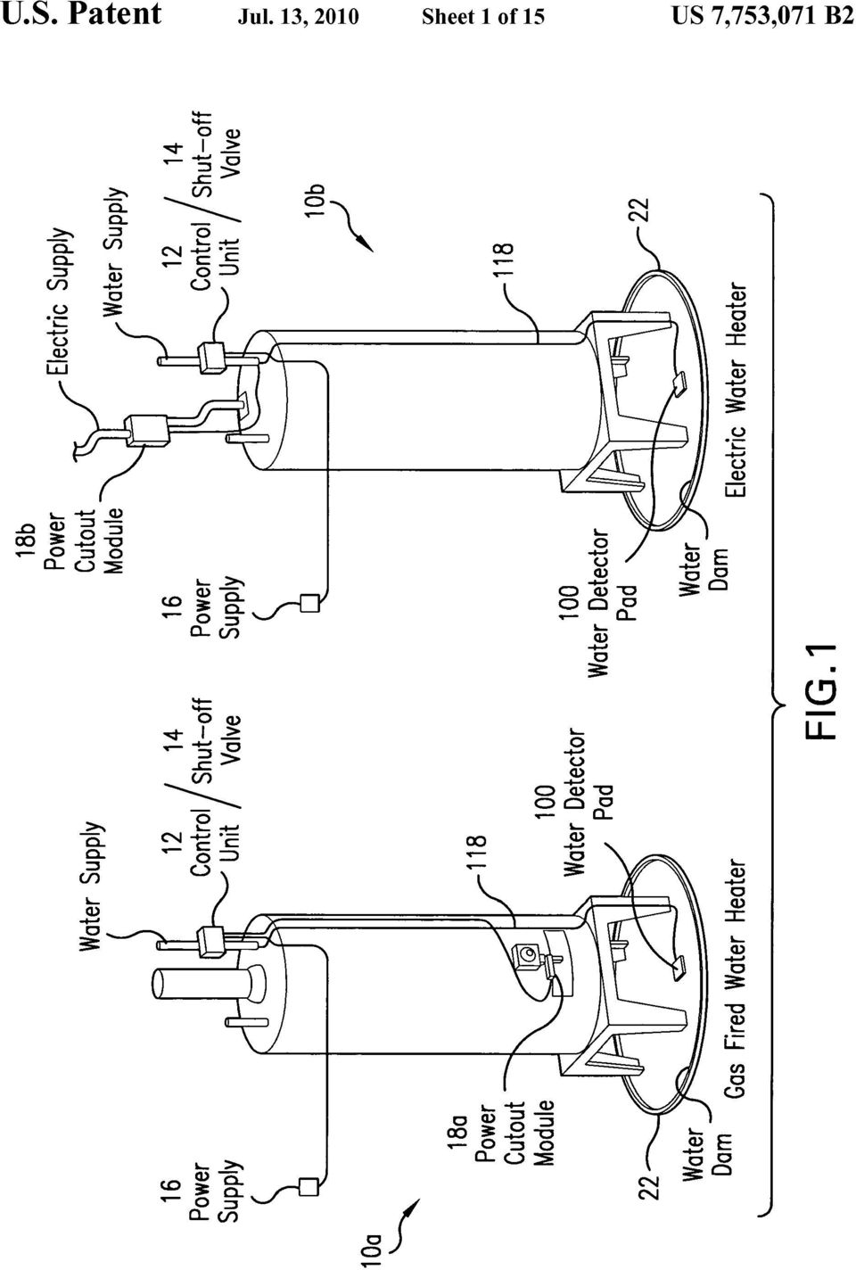
17 1 LEAK DETECTOR PAD CROSS-REFERENCE TO RELATED APPLICATION This application claims priority to US. Provisional Patent Application No. 60/884,566?led Jan. 11, 2007, Which is incorporated herein by reference. TECHNICAL FIELD OF THE DISCLOSURE The present disclosure generally relates to a Water sensor and, more particularly, to a leak detector pad including a Water sensor. Even more particularly, the present disclosure relates to a Water detector shut-off system that includes a leak detector pad for detecting Water leakage from household appliances, such as hot Water heaters, and shut-off mecha nisms, such as Water valves, for shutting off Water supply to a leaking appliance. BACKGROUND OF THE DISCLOSURE Household?ooding costs homeowners and insurance com panies millions of dollars in damages every year in the United States alone. Bursting pipes or leaking or malfunctioning appliances, for instance, can cause such household?ooding. The resultant?ooding often causes damage to the surround ing environment as Well as to the appliance itself. For example,?ooding of laundry rooms is such a common occur rence that many housing codes now require Washing machines to be positioned Within catch basins. Thus, When the inevitable over?ow occurs, it is hoped that the Water Will be contained Within the catch basins and that the Water Will not?ow into other regions of the laundry rooms. HoWever, unless the manually operated shut-off valves, Which are typically positioned at the Wall behind most Wash ing machines, are closed, Water can surge unrestricted through a burst supply hose or can spill from the tank of the malfunctioning Washing machine. It is estimated that the unrestricted?ow through the hoses or from the tanks can be on the order of 3 gallons per minute or 180 gallons an hour. Clearly, in an unmonitored situation, the?ow of Water Will rapidly exceed the storage capacity of a catch basin and also can exceed the capacity of a drain positioned Within the catch basin. Toilets can be a source of?ooding as Well. Generally, toilets include both a?oat valve and a seal that stops the?ow of Water into the toilet. If a drain line of the toilet becomes plugged, or if the?oat valve or seal malfunctions, Water can spill from Within the toilet bowl or re?ll tank onto the?oor. In addition, the Water supply line to the toilet can become loos ened or can fail. In such instances, Water Will be surging onto the bathroom?oor until the manually operated valve, Which is typically located behind the toilet, is shut off. Thus, large amounts of Water can?ood a bathroom if the condition remains unmonitored. Water heaters can also be a source of?ooding. If a tank of the Water heater springs a leak or if a Water line connected to the Water heater breaks, Water Will surge into the dwelling until the supply valve to the Water heater is shut off. With Water heaters, however, it is also desirable to shut off the?ow of electricity and heating fuel, such as oil or gas, to the Water heater. Many prior art appliance leak detector and shut-off systems include a Water sensor, or leak detector pad, a controller, and a Water supply valve. The leak detector pad is placed on the?oor near an appliance to be monitored. Upon contacting US 7,753,071 B Water during?ooding, the detector pad sends a signal to the control, Which in turn causes the Water supply valve to close to prevent further?ooding. What is still desired is a new and improved leak detector pad. Preferably the leak detector pad Will be compact, rugge dized, Waterproof, include no moving parts, be protected from dirt and corrosion, and be reusable after a?ood. In addition, the leak detector pad Will preferably be able to transmit an alarm signal a relatively long distance, such as 150 feet. SUMMARY OF THE DISCLOSURE The present disclosure provides a new and improved leak detector pad. According to one exemplary embodiment, the pad includes a circuit board having a bottom surface and a top surface, spaced?rst and second electrically conductive traces located on the bottom surface, and an electronic circuit mounted on the top surface. The circuit includes a?rst seg ment adapted to create an alternating current (AC) voltage Waveform, a second segment adapted to apply the AC voltage Waveform between the traces on the bottom surface of the circuit board, a third segment adapted to create a measure of a capacitance between the traces based upon an AC current?owing between the traces as a result of the AC voltage Waveform, and a fourth segment adapted to create a direct current (DC) voltage alarm signal if the measure of capaci tance provided by the third segment indicates the presence of?uid. According to one aspect, the leak detector pad further includes a Watertight encapsulation layer covering the top and bottom surfaces of the circuit board and the electronic circuit and the traces. According to an additional aspect, the pad also includes a relatively thicker shock-absorbing, Watertight over-mold layer covering the encapsulation layer on the top surface of the circuit board and the electronic circuit, side edges of the circuit board, and the encapsulation layer on edge portions of the bottom surface of the circuit board. Among other aspects and advantages, the new and improved leak detector pad of the present disclosure is com pact, ruggedized, Waterproof, includes no moving parts, is protected from dirt and corrosion, and can be reused after a?ood. In addition, the DC voltage alarm signal produced by the leak detector pad can be transmitted a relatively long distance. Additional aspects and advantages of the present disclo sure Will become readily apparent to those skilled in this art from the following detailed description, Wherein only an exemplary embodiment of the present disclosure is shown and described, simply by Way of illustration of the best mode contemplated for carrying out the present disclosure. As Will be realized, the present disclosure is capable of other and different embodiments, and its several details are capable of modi?cations in various obvious respects, all Without depart ing from the disclosure. Accordingly, the drawings and description are to be regarded as illustrative in nature, and not as restrictive. BRIEF DESCRIPTION OF DRAWINGS Reference is made to the attached drawings, Wherein ele ments having the same reference character designations rep resent like elements throughout, and Wherein: FIG. 1 is a perspective view of two exemplary embodi ments of Water heater leak detector shut-off systems includ ing leak detector pads constructed in accordance With the present disclosure;

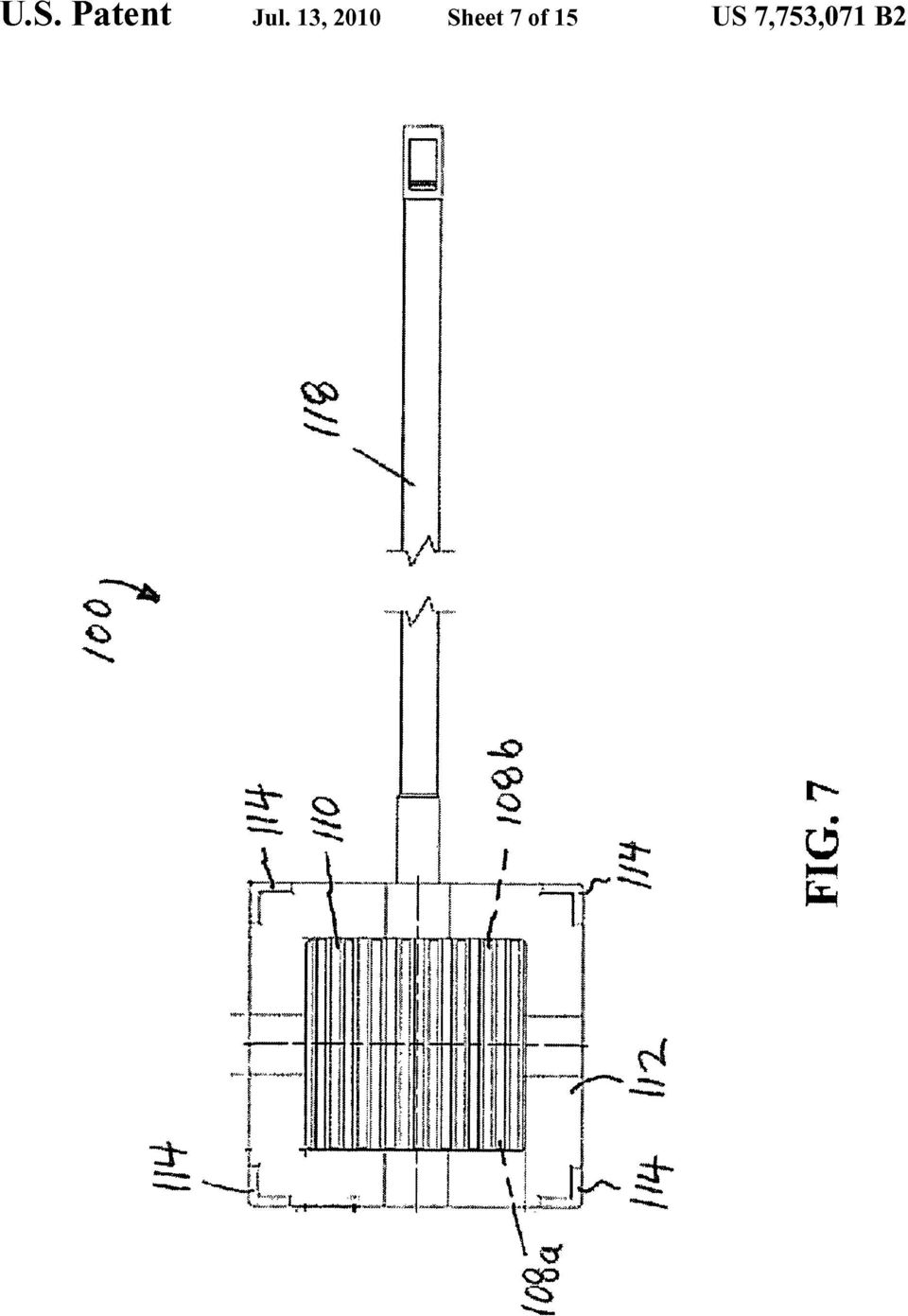
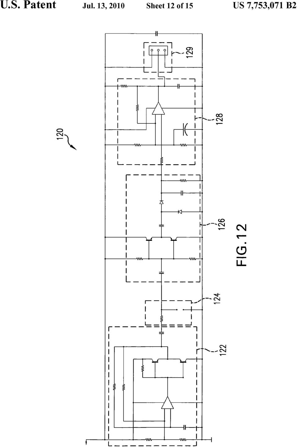
18 3 FIG. 2 is an enlarged top plan view of the leak detector pad of FIG. 1; FIG. 3 is a further enlarged top plan view of the leak detector pad of FIG. 1; FIG. 4 is an enlarged side elevation view of the leak detec tor pad of FIG. 1; FIG. 5 is a further enlarged side elevation view of the leak detector pad of FIG. 1; FIG. 6 is an even further enlarged side elevation view of a portion of the leak detector pad of FIG. 1 contained Within circle 6 of FIG. 5; FIG. 7 is an enlarged bottom plan view of the leak detector pad of FIG. 1; FIG. 8 is a further enlarged bottom plan view of the leak detector pad of FIG. 1; FIG. 9; is a plan view of a bottom surface of a circuit board of the leak detector pad of FIG. 1, Wherein exemplary embodiments of two traces according to the present disclo sure are shown; FIG. 10 is a plan view of a top surface of the circuit board of the leak detector pad of FIG. 1, Wherein an exemplary embodiments of a layout of an electronic circuit according to the present disclosure is shown; FIG. 11 is a block diagram of the electronic circuit of the leak detector pad of FIG. 1; FIG. 12 is an exemplary embodiment of an electrical sche matic of the electronic circuit of the leak detector pad of FIG. 1; and FIGS. 13A, 13B, and 13C are an enlarged view of the schematic of FIG. 12. DETAILED DESCRIPTION OF EXEMPLARY EMBODIMENTS Referring to FIG. 1, there are shown two exemplary embodiments of Water heater leak detector shut-off systems 10a, 10b including new and improved leak detector pads 100 constructed in accordance With the present disclosure. Among other bene?ts, the new and improved leak detector pad 100 of the present disclosure is compact, ruggedized, Waterproof, includes no moving parts, is protected from dirt and corrosion, and can be reused after a?ood. In addition, the leak detector pad 100 can transmit a signal a relatively long distance, such as 150 feet. FIGS provide further detailed views of the detector pad 100, but?rst the shut-off systems 10a, 10b are discussed to provide background information for the detector pad. In FIG. 1 there is shown a gas Water heater and an electric Water heater. In both cases, the shut-off systems 10a, 10b include a control unit 12, a Water supply shut-off valve 14, and a power supply 16 in addition to the leak detector pads 100. The power supply 16 is adapted to receive an alternating current (AC) voltage and convert the AC voltage to a direct current (DC) voltage for the shut-off system. For the gas Water heater, the shut-off system 1011 also includes a power cutout module 1811 for a natural gas burner of the heater (for oil heaters the power cutout module is connected to an oil burner), While for the electric Water heater the shut-off system 10b includes a power cutout module 18b for an electricity supply line connected to the heater. The shut-off systems also include Water dams 22, Which surround the Water detector pads 100 to collect Water leaking from the heaters. During a?ood that is a result of a leak from the Water heaters, Water collects around the Water detector pads 100 and the pads send alarm signals to the control units 12, Which in turn activate the shut-off valves 14 and the power cutout modules 18a, 18b. The control units 12 also include alarms, US 7,753,071 B such as a noisemaker and/ or a light, to indicate that the Water heater has been shut off due to a leak. The shut-off systems 1 0a, 1 0b thereby prevent additional Water, power, and natural gas from reaching the Water heaters until the heater is?xed and the shut-off systems 10a, 10b reset. Because of the Water proof construction of the detector pads 100, the pads can be dried and reused once the?oor is also dried. Referring now to FIGS. 2-13, the leak detector pad 100 includes a circuit board 102 having a bottom surface 104 and a top surface 106, spaced?rst and second electrically con ductive traces 108a, 108b located on the bottom surface of the circuit board 104, as shown best in FIG. 9, and an electronic circuit 120 mounted on the top surface 106 of the circuit board 102, as shown best in FIG. 10. A Watertight encapsulation layer 110 covers the bottom surface 104 of the circuit board 102 and the traces 108a, 108b and the top surface 106 of the circuit board and the electronic circuit 120. The encapsulation layer 1 10 can be seen, for example, in the enlarged view of the pad 100 shown in FIG. 6. According to one exemplary embodiment, the Waterproof encapsulation layer 100 com prises a thermoplastic polyamide, such as the MAC ROMELT OM line of low pressure molding materials avail able from Henkel in Dusseldorf, Germany. The leak detectorpad 100 also includes a relatively thicker, shock-absorbing, Watertight over-mold layer 112 covering the encapsulation layer 110 on the top surface 106 of the circuit board 102 and the electronic circuit 120, side edges of the circuit board 102, and the encapsulation layer 110 on edge portions of the bottom surface 104 of the circuit board. As shown best in FIGS. 7 and 8, the over-mold layer 112 does not extend over?ngers of the traces 108a, 108b. The over-mold layer 112 includes legs 114 extending from the edge portions of the bottom surface 104 of the circuit board 120, as shown best in FIGS According to one exemplary embodiment, the over-mold layer 112 also comprises a thermoplastic polyamide, such as the MACROMELT OM line of low pressure molding materials. Referring to FIG. 9, the traces 108a, 108b comprise co planer inter-digitated?ngers. The traces 108a, 108b are made of an electrically conductive material, such as copper, and are connected to the electronic circuit 120 through holes 116a, 116b in the circuit board 102. The holes 116a, 116b can be seen, for example, in FIG. 10. Referring to FIGS , the electronic circuit 120 includes a?rst segment 122 adapted to create anac voltage Waveform from the DC voltage provided by the control unit 12, a second segment 124 adapted to apply the AC voltage Waveform between the traces 108a, 108b on the bottom sur face 104 of the circuit board 102, a third segment 126 adapted to create a DC voltage indicative of a measure of a capaci tance between the traces 108a, 108b based upon an AC cur rent?owing between the traces 108a, 108b as a result of the AC voltage Waveform, and a fourth segment 128 adapted to create a DC voltage alarm signal if the measure of capacitance provided by the third segment 126 indicates the presence of?uid. The electronic circuit 120 further includes a?fth segment 129 connected to a cable 118 for connection to the control unit 12. The?fth segment 129 is adapted to provide electrical power to the other segments of the circuit 120 and receive the DC voltage alarm signal from the fourth segment 128. The Watertight over-mold layer 112 extends over a portion of the cable 118 to provide strain relief. The present disclosure, therefore, provides a new and improved leak detector pad. It should be understood, how ever, that the exemplary embodiment described in this speci?cation has been presented by Way of illustration rather than

19 5 limitation, and various modi?cations, combinations and sub stitutions may be effected by those skilled in the art Without departure either in spirit or scope from this disclosure in its broader aspects and as set forth in the appended claims. Accordingly, other embodiments are Within the scope of the following claims. In addition, the leak detector pad disclosed herein, and all elements thereof, are contained Within the scope of at least one of the following claims. No elements of the presently disclosed leak detector pad are meant to be disclaimed. What is claimed is: 1. A leak detector pad comprising: a circuit board having a bottom surface and a top surface; spaced?rst and second electrically conductive traces located on the bottom surface of the circuit board; an electronic circuit mounted on the top surface of the circuit board and including, a?rst segment adapted to create an alternating current (AC) voltage Waveform, a second segment adapted to apply the AC voltage Wave form between the traces on the bottom surface of the circuit board, a third segment adapted to create a measure of a capaci tance between the traces based upon an AC current?owing between the traces as a result of the AC volt age Waveform, and a fourth segment adapted to create a direct current (DC) voltage alarm signal if the measure of capacitance provided by the third segment indicates a presence of?uid. 2. A leak detector pad according to claim 1, further com prising a Watertight encapsulation layer covering the bottom surface of the circuit board and the traces. 3. A leak detector pad according to claim 2, Wherein the Watertight encapsulation layer also covers the top surface of the circuit board and the electronic circuit. 4. A leak detector pad according to claim 3, further com prising a relatively thicker shock-ab sorbing, Watertight over mold layer covering the encapsulation layer on the top surface of the circuit board and the electronic circuit, side edges of the circuit board, and the encapsulation layer on edge portions of the bottom surface of the circuit board. 5. A leak detector pad according to claim 4, Wherein the over-mold layer includes legs extending from the edge por tions of the bottom surface of the circuit board. 6. A leak detector pad according to claim 4, further com prising a cable connected to the electronic circuit and Wherein the Water-tight over-mold layer extends over a portion of the cable to provide strain relief. 7. A leak detector pad according to claim 1, Wherein the traces comprise inter-digitated?ngers. 8. A leak detector pad according to claim 6, Wherein the traces are co-planar. 9. A leak detector pad according to claim 1, Wherein the traces are copper. 10. A leak detector pad according to claim 1, Wherein the traces are connected to the electronic circuit through holes in the circuit board. 11. A leak detector pad according to claim 1, Wherein the third segment of the electronic circuit is adapted to create a DC voltage indicative of the measure of the capacitance between the traces. US 7,753,071 B A leak detector pad according to claim 1, Wherein the electronic circuit further includes a?fth segment connected to at least one cable for connection to a source of electrical power and a device for receiving the DC voltage alarm signal, Wherein the?fth segment is adapted to provide electrical power to the other segments of the circuit and receive the DC voltage alarm signal from the fourth segment. 13. A leak detector pad according to claim 12, Wherein the electronic circuit is adapted to receive electrical power in the form of a DC voltage. 14. A Water detector shut-off system including the leak detector pad of claim 1 and further including: a valve for controlling a Water supply; and a controller adapted to close the valve upon receiving the DC voltage alarm signal from the leak detector pad. 15. A system according to claim 14, further comprising an alarm, Wherein the controller is adapted to activate the alarm upon receiving the DC voltage alarm signal from the leak detector pad and activate power cutout modules to shut off power. 16. A system according to claim 15, further comprising a dam surrounding the detector pad, a reset button associated With the controller adapter, and a noisemaker/warning light associated With the alarm. 17. A leak detector pad comprising: a circuit board having a bottom surface and a top surface, and holes connecting the bottom and top surfaces; spaced?rst and second electrically conductive traces located on the bottom surface of the circuit board; and an electronic circuit mounted on the top surface of the circuit board and connected to the traces through the holes in the board, the circuit including, means for creating an alternating current (AC) voltage Waveform, means for applying the AC voltage Waveform between the traces on the bottom surface of the circuit board, means for creating a measure of a capacitance between the traces based upon an AC current?owing between the traces as a result of the AC voltage Waveform, and means for creating a direct current (DC) voltage alarm signal if the measure of capacitance indicates the presence of?uid. 18. A leak detector pad according to claim 17, further comprising a Watertight encapsulation layer covering the bot tom surface of the circuit board and the traces. 19. A leak detector pad comprising: a circuit board having a bottom surface and a top surface, and holes connecting the bottom and top surfaces; spaced?rst and second electrically conductive traces located on the bottom surface of the circuit board; an electronic circuit mounted on the top surface of the circuit board and connected to the traces through the holes in the board, the circuit adapted to measure a capacitance between the traces, and create a direct cur rent (DC) voltage alarm signal if the capacitance indi cates the presence of?uid; and a Water-tight encapsulation layer covering the bottom sur face of the circuit board and the traces. 20. A leak detector pad according to claim 19, Wherein the Watertight encapsulation layer also covers the top surface of the circuit board and the electronic circuit. * * * * *

Emergency Spill Basis For Collecting And Collecting?
 United States Patent [191 Verstraeten [54] EMERGENCY SPILL BASIN [75] [73] Inventor: Assignee: Alexander J. Verstraeten, Knokke-Heist, Belgium Funderingstechnieken Verstraeten B. V., Oostburg, Netherlands
US 20070139188A1 (19) United States (12) Patent Application Publication (10) Pub. No.: US 2007/0139188 A1 Ollis et al. HOME PROCESSOR /\ J\ NETWORK
 United States (12) Patent Application Publication (10) Pub. No.: US 2007/0139188 A1 Ollis et al. HOME PROCESSOR /\ J\ NETWORK") US 20070139188A1 (19) United States (12) Patent Application Publication (10) Pub. No.: US 2007/0139188 A1 Ollis et al. (43) Pub. Date: Jun. 21, 2007 (54) (75) (73) (21) (22) METHOD AND APPARATUS FOR COMMUNICATING
US 20070139188A1 (19) United States (12) Patent Application Publication (10) Pub. No.: US 2007/0139188 A1 Ollis et al. (43) Pub. Date: Jun. 21, 2007 (54) (75) (73) (21) (22) METHOD AND APPARATUS FOR COMMUNICATING
\ \ \ connection connection connection interface interface interface
 US 20140122910A1 (19) United States (12) Patent Application Publication (10) Pub. No.: US 20140122910 A1 Chiu et al. (43) Pub. Date: May 1, 2014 (54) RACK SERVER SYSTEM AND OPERATION Publication Classi?cation
(12) United States Patent (10) Patent No.: US 8,253,226 B2 Oguri (45) Date of Patent: Aug. 28, 2012
 United States Patent (10) Patent No.: US 8,253,226 B2 Oguri (45) Date of Patent: Aug. 28, 2012") US008253226B2 (12) United States Patent (10) Patent No.: US 8,253,226 B2 Oguri (45) Date of Patent: Aug. 28, 2012 (54) ELECTRONIC PARTS, AND METHOD FOR (56) References Cited ARRANGING SHIELDING CASE AND
US008253226B2 (12) United States Patent (10) Patent No.: US 8,253,226 B2 Oguri (45) Date of Patent: Aug. 28, 2012 (54) ELECTRONIC PARTS, AND METHOD FOR (56) References Cited ARRANGING SHIELDING CASE AND
US 20110043191A1 (19) United States (12) Patent Application Publication (10) Pub. No.: US 2011/0043191 A1 Gutierrez (43) Pub. Date: Feb.
 United States (12) Patent Application Publication (10) Pub. No.: US 2011/0043191 A1 Gutierrez (43) Pub. Date: Feb.") US 20110043191A1 (19) United States (12) Patent Application Publication (10) Pub. No.: US 2011/0043191 A1 Gutierrez (43) Pub. Date: Feb. 24, 2011 (54) PHOENIX PROBE X VOLTAGE TESTER Publication Classi?cation
US 20110043191A1 (19) United States (12) Patent Application Publication (10) Pub. No.: US 2011/0043191 A1 Gutierrez (43) Pub. Date: Feb. 24, 2011 (54) PHOENIX PROBE X VOLTAGE TESTER Publication Classi?cation
(12) United States Patent (16) Patent N6.= US 6,198,814 B1 Gill (45) Date of Patent: Mar. 6, 2001
 United States Patent (16) Patent N6.= US 6,198,814 B1 Gill (45) Date of Patent: Mar. 6, 2001") US006198814B1 (12) United States Patent (16) Patent N6.= Gill (45) Date of Patent: Mar. 6, 2001 (54) SYSTEM AND METHOD FOR ENTERING 5,621,790 * 4/1997 Grossman 6161...... 379/266 CALL OUTCOME RECORDS IN
US006198814B1 (12) United States Patent (16) Patent N6.= Gill (45) Date of Patent: Mar. 6, 2001 (54) SYSTEM AND METHOD FOR ENTERING 5,621,790 * 4/1997 Grossman 6161...... 379/266 CALL OUTCOME RECORDS IN
(71) Applicant: SPEAKWRITE, LLC,Austin, TX (US)
 Applicant: SPEAKWRITE, LLC,Austin, TX (US)") US 20130304465Al (19) United States (12) Patent Application Publication (10) Pub. No.: US 2013/0304465 A1 Henry et al. (43) Pub. Date: NOV. 14, 2013 (54) METHOD AND SYSTEM FOR AUDIO-VIDEO (52) US. Cl.
US 20130304465Al (19) United States (12) Patent Application Publication (10) Pub. No.: US 2013/0304465 A1 Henry et al. (43) Pub. Date: NOV. 14, 2013 (54) METHOD AND SYSTEM FOR AUDIO-VIDEO (52) US. Cl.
(12) United States Patent Armenio et a].
![(12) United States Patent Armenio et a].](/thumbs/40/20558097.jpg "(12) United States Patent Armenio et a].") US008425210B2 (12) United States Patent Armenio et a]. (10) Patent N0.: (45) Date of Patent: Apr. 23, 2013 (54) TWO-SETTINGVARIABLE-ECCENTRICITY VANE PUMP (75) Inventors: Giacomo Armenio, Livorno (IT);
US008425210B2 (12) United States Patent Armenio et a]. (10) Patent N0.: (45) Date of Patent: Apr. 23, 2013 (54) TWO-SETTINGVARIABLE-ECCENTRICITY VANE PUMP (75) Inventors: Giacomo Armenio, Livorno (IT);
(12) United States Patent
 United States Patent") US008914855B2 (12) United States Patent Whitmyer, Jr. (10) Patent N0.: (45) Date of Patent: US 8,914,855 B2 Dec. 16, 2014 (54) PORTABLE PASSWORD KEEPER WITH INTERNET STORAGE AND RESTORE (75) Inventor:
US008914855B2 (12) United States Patent Whitmyer, Jr. (10) Patent N0.: (45) Date of Patent: US 8,914,855 B2 Dec. 16, 2014 (54) PORTABLE PASSWORD KEEPER WITH INTERNET STORAGE AND RESTORE (75) Inventor:
(12> Ulllted States Patent (10) Patent N0.: US 6,591,288 B1 Edwards et al. (45) Date of Patent: Jul. 8, 2003
 Patent N0.: US 6,591,288 B1 Edwards et al. (45) Date of Patent: Jul. 8, 2003") ' ' US006591288B1 (12> Ulllted States Patent (10) Patent N0.: Edwards et al. (45) Date of Patent: Jul. 8, 2003 (54) DATA NETWORK ACCELERATED ACCESS EP 0837584 4/1998..... H04L/29/06 SYSTEM W0 WO 96/34340
' ' US006591288B1 (12> Ulllted States Patent (10) Patent N0.: Edwards et al. (45) Date of Patent: Jul. 8, 2003 (54) DATA NETWORK ACCELERATED ACCESS EP 0837584 4/1998..... H04L/29/06 SYSTEM W0 WO 96/34340
(54) (71) (72) Vedelago (TV) (IT) (73) (21) (22) (30) Chirignago (VE) (IT); Alberto Al?er, Foreign Application Priority Data
 (71) (72) Vedelago (TV) (IT) (73) (21) (22) (30) Chirignago (VE) (IT); Alberto Al?er, Foreign Application Priority Data") US 20130094227Al (19) United States (12) Patent Application Publication (10) Pub. No.: US 2013/0094227 A1 Scordino et al. (43) Pub. Date: Apr. 18, 2013 (54) (71) (72) (73) (21) (22) (30) MOUNTING DEVICE
US 20130094227Al (19) United States (12) Patent Application Publication (10) Pub. No.: US 2013/0094227 A1 Scordino et al. (43) Pub. Date: Apr. 18, 2013 (54) (71) (72) (73) (21) (22) (30) MOUNTING DEVICE
United States Patent [191 [11] Patent Number: 4,895,256
![United States Patent [191 [11] Patent Number: 4,895,256](/thumbs/29/13744178.jpg "United States Patent [191 [11] Patent Number: 4,895,256") I United States Patent [191 [11] Patent Number: 4,895,256 Johnston [45] Date of Patent: Jan. 23, 1990 [54] AIR CONDITIONING SUPPLY CARRIER 3,392,874 7/1968 3,627,122 12/1971 [76] Inventor: James E. Johnston,
I United States Patent [191 [11] Patent Number: 4,895,256 Johnston [45] Date of Patent: Jan. 23, 1990 [54] AIR CONDITIONING SUPPLY CARRIER 3,392,874 7/1968 3,627,122 12/1971 [76] Inventor: James E. Johnston,
IIIIIIIIIIIIIIIIIIIIIIIIIIIIIIn -_
 V,. v 1 US 20080196974A1 (19) United States (12) Patent Appl lca tlol Publication (10) Pub. N0.: US 2008/ 0196974 A1 GALVEL (43) Pub. Date: (54) DEVCE AND METHOD OF STANDBY LUBRFCATON FOR AN ENGNE (75)
United States Patent [191
 United States Patent [191 Fancy [54] REDUNDANT SIGNAL CIRCUIT [75] Inventor: Thomas A. Fancy, Westminster, Mass. [73] Assignee: General Electric Company, Schenectady, NY. [211 Appl. No.: 854,973 [22] Filed:
United States Patent [191 Romo et al.
 United States Patent [191 Romo et al. [54] APPARATUS FOR PREVENTING NECK INJURY [76] Inventors: Leon E. Romo, Box 1 A Rt. 5, Annapolis, Md. 211; Jack T. Andrish, 120 E. 216 St., Euclid, Ohio 44123 [22]
(12) United States Patent (10) Patent N0.: US 7,068,424 B1 Jennings et al. (45) Date of Patent: Jun. 27, 2006
 United States Patent (10) Patent N0.: US 7,068,424 B1 Jennings et al. (45) Date of Patent: Jun. 27, 2006") US007068424B1 (12) United States Patent (10) Patent N0.: US 7,068,424 B1 Jennings et al. (45) Date of Patent: Jun. 27, 2006 (54) MULTIPLE PULSE GENERATION 6,141,127 A * 10/2000 Boivin et a1...... 398/92
US007068424B1 (12) United States Patent (10) Patent N0.: US 7,068,424 B1 Jennings et al. (45) Date of Patent: Jun. 27, 2006 (54) MULTIPLE PULSE GENERATION 6,141,127 A * 10/2000 Boivin et a1...... 398/92
US 20090157756Al (19) United States (12) Patent Application Publication (10) Pub. No.: US 2009/0157756 A1 Sanvido (43) Pub. Date: Jun.
 United States (12) Patent Application Publication (10) Pub. No.: US 2009/0157756 A1 Sanvido (43) Pub. Date: Jun.") US 20090157756Al (19) United States (12) Patent Application Publication (10) Pub. No.: US 2009/0157756 A1 Sanvido (43) Pub. Date: Jun. 18, 2009 (54) FILE SYSTEM FOR STORING FILES IN Publication Classi?cation
US 20090157756Al (19) United States (12) Patent Application Publication (10) Pub. No.: US 2009/0157756 A1 Sanvido (43) Pub. Date: Jun. 18, 2009 (54) FILE SYSTEM FOR STORING FILES IN Publication Classi?cation
software, and perform automatic dialing according to the /*~102
 US 20140105199A1 (19) United States (12) Patent Application Publication (10) Pub. No.: US 2014/0105199 A1 Tian (43) Pub. Date: (54) METHOD AND APPARATUS FOR AUTOMATIC DIALING ACCESS POINTS (71) Applicant:
Plumbing Identification and Damage Assessment Guide
 Plumbing Identification and Damage Assessment Guide *Please note that not all systems will be represented exactly by these diagrams and photos. As a vendor, it is required that you familiar yourself with
(12) United States Patent (10) Patent No.: US 8,349,484 B2 Do et a]. (45) Date of Patent: Jan. 8, 2013
![(12) United States Patent (10) Patent No.: US 8,349,484 B2 Do et a]. (45) Date of Patent: Jan. 8, 2013](/thumbs/40/20543675.jpg "(12) United States Patent (10) Patent No.: US 8,349,484 B2 Do et a]. (45) Date of Patent: Jan. 8, 2013") US008349484B2 (12) United States Patent (10) Patent No.: US 8,349,484 B2 Do et a]. (45) Date of Patent: Jan. 8, 2013 (54) STACKING METHOD OF HIGH POWER 2007/0072083 A1 * 3/2007 Ikuta et al...... 429/246
US008349484B2 (12) United States Patent (10) Patent No.: US 8,349,484 B2 Do et a]. (45) Date of Patent: Jan. 8, 2013 (54) STACKING METHOD OF HIGH POWER 2007/0072083 A1 * 3/2007 Ikuta et al...... 429/246
US 201203 03424Al (19) United States (12) Patent Application Publication (10) Pub. N0.: US 2012/0303424 A1 Lundstrom (43) Pub. Date: NOV.
 United States (12) Patent Application Publication (10) Pub. N0.: US 2012/0303424 A1 Lundstrom (43) Pub. Date: NOV.") US 201203 03424Al (19) United States (12) Patent Application Publication (10) Pub. N0.: US 2012/0303424 A1 Lundstrom (43) Pub. Date: NOV. 29, 2012 (54) METHOD AND SOFTWARE FOR Publication Classi?cation
US 201203 03424Al (19) United States (12) Patent Application Publication (10) Pub. N0.: US 2012/0303424 A1 Lundstrom (43) Pub. Date: NOV. 29, 2012 (54) METHOD AND SOFTWARE FOR Publication Classi?cation
(12) Patent Application Publication (10) Pub. No.: US 2003/0035525 A1 Wu et al. (43) Pub. Date: Feb. 20, 2003
 Patent Application Publication (10) Pub. No.: US 2003/0035525 A1 Wu et al. (43) Pub. Date: Feb. 20, 2003") (19) United States US 20030035525A1 (12) Patent Application Publication (10) Pub. No.: US 2003/0035525 A1 Wu et al. (43) Pub. Date: (54) (76) (21) (22) SYSTEM AND METHOD FOR DISTINGUISHING TELEPHONE NUMBER
(19) United States US 20030035525A1 (12) Patent Application Publication (10) Pub. No.: US 2003/0035525 A1 Wu et al. (43) Pub. Date: (54) (76) (21) (22) SYSTEM AND METHOD FOR DISTINGUISHING TELEPHONE NUMBER
How To Fix A Leaky Water Heater
 Preventing water damage caused by plumbing fixtures Thousands of home insurance claims are filed every year. Some losses are major, others aren t, but they re always inconvenient and usually avoidable!
1iillllllllllllllilllllllllllllllllllllllllllllllllillllllllllllllllllllill
 1iillllllllllllllilllllllllllllllllllllllllllllllllillllllllllllllllllllill USO05615608A Ulllt d States Patent [19] [11] Patent Number: 5,615,608 Shaw et a]. [45] Date of Patent: Apr. 1, 1997 [54] REINFORCED
llllllllllllllillllllllllllllllllllllllllllllllllllllllllllllllllllllllllll
 llllllllllllllillllllllllllllllllllllllllllllllllllllllllllllllllllllllllll USOO5535162A United States Patent [19] [11] Patent Number: 5,535,162 Uenoyama [45] Date of Patent: Jul. 9, 1996 [54] ELECTRICALLY
(30) Foreign Application Priority Data
 Foreign Application Priority Data") US 20110149572A1 (19) United States (12) Patent Application Publication (10) Pub. No.: US 2011/0149572 A1 Yu-chow (43) Pub. Date: Jun. 23, 2011 (54) ROPE LIGHT (76) Inventor: K0 Yu-choW, Hong Kong SAR
US 20110149572A1 (19) United States (12) Patent Application Publication (10) Pub. No.: US 2011/0149572 A1 Yu-chow (43) Pub. Date: Jun. 23, 2011 (54) ROPE LIGHT (76) Inventor: K0 Yu-choW, Hong Kong SAR
Telephone Dressing Systems - Advantages and Disadvantages
 I US 20030185352A1 (19) United States (12) Patent Application Publication (10) Pub. No.: US 2003/0185352 A1 Savage et al. (43) Pub. Date: (54) AUTOMATED MESSAGE BROADCAST SYSTEM WITH DUAL MESSAGE SOURCES
(12) Ulllted States Patent (10) Patent N0.: US 8,389,837 B1 Leguia (45) Date of Patent: Mar. 5, 2013
 Ulllted States Patent (10) Patent N0.: US 8,389,837 B1 Leguia (45) Date of Patent: Mar. 5, 2013") US008389837B1 (12) Ulllted States Patent (10) Patent N0.: US 8,389,837 B1 Leguia (45) Date of Patent: Mar. 5, 2013 (54) STRINGED INSTRUMENT HAVINGA 4,836,076 A 6/1989 Bernier FRETBOARD CANTILEVERED OVER
US008389837B1 (12) Ulllted States Patent (10) Patent N0.: US 8,389,837 B1 Leguia (45) Date of Patent: Mar. 5, 2013 (54) STRINGED INSTRUMENT HAVINGA 4,836,076 A 6/1989 Bernier FRETBOARD CANTILEVERED OVER
US 20020116467A1 (19) United States (12) Patent Application Publication (10) Pub. No.: US 2002/0116467 A1 Boyer et al. (43) Pub. Date: Aug.
 United States (12) Patent Application Publication (10) Pub. No.: US 2002/0116467 A1 Boyer et al. (43) Pub. Date: Aug.") US 20020116467A1 (19) United States (12) Patent Application Publication (10) Pub. No.: US 2002/0116467 A1 Boyer et al. (43) Pub. Date: Aug. 22, 2002 (54) METHOD AND APPARATUS FOR Publication Classi?cation
US 20020116467A1 (19) United States (12) Patent Application Publication (10) Pub. No.: US 2002/0116467 A1 Boyer et al. (43) Pub. Date: Aug. 22, 2002 (54) METHOD AND APPARATUS FOR Publication Classi?cation
Home comfort: water heating
 Home comfort: water heating Water heating usage Hot water. It s one of those luxuries we give little thought to until we run out. This information is provided to help you get the most value and comfort
(12) United States Patent (10) Patent No.: US 8,512,370 B2 Sorensen (45) Date of Patent: Aug. 20, 2013
 United States Patent (10) Patent No.: US 8,512,370 B2 Sorensen (45) Date of Patent: Aug. 20, 2013") US008512370B2 (12) United States Patent (10) Patent No.: US 8,512,370 B2 Sorensen (45) Date of Patent: Aug. 20, 2013 (54) PILLOW WITH PLURALITY OF BALLS FOR (56) References Cited RELIEVING SINUS AND CONGESTION
US008512370B2 (12) United States Patent (10) Patent No.: US 8,512,370 B2 Sorensen (45) Date of Patent: Aug. 20, 2013 (54) PILLOW WITH PLURALITY OF BALLS FOR (56) References Cited RELIEVING SINUS AND CONGESTION
(12) United States Patent Edelen
 United States Patent Edelen") US008285799B2 (12) United States Patent Edelen (10) Patent N0.: (45) Date of Patent: Oct. 9, 2012 (54) QUOTA-BASED ARCHIVING (75) Inventor: James Edelen, Renton, WA (U S) (73) Assignee: Microsoft Corporation,
US008285799B2 (12) United States Patent Edelen (10) Patent N0.: (45) Date of Patent: Oct. 9, 2012 (54) QUOTA-BASED ARCHIVING (75) Inventor: James Edelen, Renton, WA (U S) (73) Assignee: Microsoft Corporation,
US 20070016324A1 (19) United States (12) Patent Application Publication (10) Pub. No.: US 2007/0016324 A1. Operating System. 106 q f 108.
 United States (12) Patent Application Publication (10) Pub. No.: US 2007/0016324 A1. Operating System. 106 q f 108.") US 20070016324A1 (19) United States (12) Patent Application Publication (10) Pub. No.: US 2007/0016324 A1 Oddiraj u et al. (43) Pub. Date: Jan. 18, 2007 (54) SYSTEM BOOT OPTMZER (75) nventors: Chandar
US 20070016324A1 (19) United States (12) Patent Application Publication (10) Pub. No.: US 2007/0016324 A1 Oddiraj u et al. (43) Pub. Date: Jan. 18, 2007 (54) SYSTEM BOOT OPTMZER (75) nventors: Chandar
(54) (75) (2006.01) (73) (21) (22) (63) Peschel, Schoengeising (DE); (30) Foreign Application Priority Data. Robert Trimpe, Wessling (DE)
 (75) (2006.01) (73) (21) (22) (63) Peschel, Schoengeising (DE); (30) Foreign Application Priority Data. Robert Trimpe, Wessling (DE)") US 20120073912Al (19) United States (12) Patent Application Publication (10) Pub. No.: US 2012/0073912 A1 CAMILO-MARTINEZ et al. (43) Pub. Date: Mar. 29, 2012 (54) (75) (73) (21) (22) (63) PNEUMATICALLY
US 20120073912Al (19) United States (12) Patent Application Publication (10) Pub. No.: US 2012/0073912 A1 CAMILO-MARTINEZ et al. (43) Pub. Date: Mar. 29, 2012 (54) (75) (73) (21) (22) (63) PNEUMATICALLY
EP 2 354 708 A2 (19) (11) EP 2 354 708 A2 (12) EUROPEAN PATENT APPLICATION. (43) Date of publication: 10.08.2011 Bulletin 2011/32
 (11) EP 2 354 708 A2 (12) EUROPEAN PATENT APPLICATION. (43) Date of publication: 10.08.2011 Bulletin 2011/32") (19) (12) EUROPEAN PATENT APPLICATION (11) EP 2 354 708 A2 (43) Date of publication:.08.2011 Bulletin 2011/32 (51) Int Cl.: F24H 3/08 (2006.01) F24H 8/00 (2006.01) (21) Application number: 111536.8 (22)
(19) (12) EUROPEAN PATENT APPLICATION (11) EP 2 354 708 A2 (43) Date of publication:.08.2011 Bulletin 2011/32 (51) Int Cl.: F24H 3/08 (2006.01) F24H 8/00 (2006.01) (21) Application number: 111536.8 (22)
3,2 74,344 AUTOMATIC DIALING DEVICE. Filed June 14, 1963. 5 Sheets-Sheet 1 24 \ l NVENTOR. CHARLES C. YOUNG / /////% B73744 2?
 Sept. 20, 1966 Filed June 14, 1963 c. c. YOUNG AUTOMATIC DIALING DEVICE 3,2 74,344 5 Sheets-Sheet 1 3 w. L? U; / m wk, m 5 V/Wh :: ///////,// F G 2 w 24 \ / /////% 2-4 l NVENTOR. CHARLES C. YOUNG B73744
' 2,092,586 SCREW DRIVER. Filed July 24, 1936. ' 2 Sheets-Sheet 1 INVENTOR. Sl qjarz Mama/{ck 1 _ / ' ATTORNEY
 Sept. 7, 1937,, s. N'AuMovlcH SCREW DRIVER Filed July 24, 1936 ' ' 2 Sheets-Sheet 1 INVENTOR Sl qjarz Mama/{ck 1 _ / ' ATTORNEY I Patented Sept. 7, 1937 UNITED STATES SCREW DRIVER PATENT OFFICE Stojan
i 1 4 115 5330355 122 123 X USE HOST USB B105 121R CONTROLLER 111a 40 11a 1 21
 US007519756B2 (12) Ulllted States Patent (10) Patent N0.: US 7,519,756 B2 Yamamoto et al. (45) Date of Patent: *Apr. 14, 2009 (54) METHOD AND APPARATUS FOR (52) US. Cl...... 710/302; 710/10; 710/14; CONTROLLING
US 20130073440A1 (19) United States (12) Patent Application Publication (10) Pub. No.: US 2013/0073440 A1 Chen (57)
 United States (12) Patent Application Publication (10) Pub. No.: US 2013/0073440 A1 Chen (57)") US 20130073440A1 (19) United States (12) Patent Application Publication (10) Pub. No.: US 2013/0073440 A1 Chen (43) Pub. Date: Mar. 21, 2013 (54) PAYROLL SYSTEM AND METHOD Publication Classi?cation (76)
US 20130073440A1 (19) United States (12) Patent Application Publication (10) Pub. No.: US 2013/0073440 A1 Chen (43) Pub. Date: Mar. 21, 2013 (54) PAYROLL SYSTEM AND METHOD Publication Classi?cation (76)
SERVICE MANUAL Order No.WH0911S001V0
 SERVICE MANUAL Order No.WH0911S001V0 Electrical Water Heater Model No. FCD-JTSA50-III FCD-JTSA60-III FCD-JTSA70-III FCD-JTSA80-III! WARNING This service information is designed for experienced repair technicians
(12) (10) Patent N0.: US 6,614,314 B2 d Haene et al. 45 Date 0f Patent: Se. 2 2003 (54) NON-LINEAR PHASE DETECTOR FOREIGN PATENT DOCUMENTS
 (10) Patent N0.: US 6,614,314 B2 d Haene et al. 45 Date 0f Patent: Se. 2 2003 (54) NON-LINEAR PHASE DETECTOR FOREIGN PATENT DOCUMENTS") United States Patent US006614314B2 (12) (10) Patent N0.: US 6,614,314 B2 d Haene et al. 45 Date 0f Patent: Se. 2 2003 a (54) NON-LINEAR PHASE DETECTOR FOREIGN PATENT DOCUMENTS (75) Inventors: Wesley Calvin
United States Patent US006614314B2 (12) (10) Patent N0.: US 6,614,314 B2 d Haene et al. 45 Date 0f Patent: Se. 2 2003 a (54) NON-LINEAR PHASE DETECTOR FOREIGN PATENT DOCUMENTS (75) Inventors: Wesley Calvin
wanagamem transformation and management
 US 20120150919Al (19) United States (12) Patent Application Publication (10) Pub. No.: US 2012/0150919 A1 Brown et al. (43) Pub. Date: Jun. 14, 2012 (54) (76) (21) (22) (60) (51) AGENCY MANAGEMENT SYSTEM
(12) United States Patent (10) Patent N0.: US 8,695,377 B2 Bachelier et a]. (45) Date of Patent: Apr. 15, 2014
![(12) United States Patent (10) Patent N0.: US 8,695,377 B2 Bachelier et a]. (45) Date of Patent: Apr. 15, 2014](/thumbs/40/20550530.jpg "(12) United States Patent (10) Patent N0.: US 8,695,377 B2 Bachelier et a]. (45) Date of Patent: Apr. 15, 2014") USOO8695377B2 (12) United States Patent (10) Patent N0.: Bachelier et a]. (45) Date of Patent: Apr. 15, 2014 (54) PROCESS AND APPARATUS FOR THE (52) us. Cl. SEPARATION OF AIR BY CRYOGENIC USPC..... 62/644;
USOO8695377B2 (12) United States Patent (10) Patent N0.: Bachelier et a]. (45) Date of Patent: Apr. 15, 2014 (54) PROCESS AND APPARATUS FOR THE (52) us. Cl. SEPARATION OF AIR BY CRYOGENIC USPC..... 62/644;
A COMPARISON OF WATER LEAK DETECTION AND SHUTOFF SYSTEMS
 A COMPARISON OF WATER LEAK DETECTION AND SHUTOFF SYSTEMS By Charles Ergle January 16, 2012 As every appraiser knows, water damage is the single highest continual source of claims at Chubb. Fires happen,
60 REDIRECTING THE PRINT PATH MANAGER 1
 US006788429B1 (12) United States Patent (10) Patent No.: US 6,788,429 B1 Clough et al. (45) Date of Patent: Sep. 7, 2004 (54) REMOTE PRINT QUEUE MANAGEMENT FOREIGN PATENT DOCUMENTS (75) Inventors: James
Hay (43) Pub. Date: Oct. 17, 2002
 Pub. Date: Oct. 17, 2002") US 20020152322A1 (19) United States (12) Patent Application Publication (10) Pub. No.: US 2002/0152322 A1 Hay (43) Pub. Date: Oct. 17, 2002 (54) (76) (21) (22) (51) (52) METHOD AND APPARATUS FOR FACILITATING
US 20020152322A1 (19) United States (12) Patent Application Publication (10) Pub. No.: US 2002/0152322 A1 Hay (43) Pub. Date: Oct. 17, 2002 (54) (76) (21) (22) (51) (52) METHOD AND APPARATUS FOR FACILITATING
EP 2 455 926 A1 (19) (11) EP 2 455 926 A1 (12) EUROPEAN PATENT APPLICATION. (43) Date of publication: 23.05.2012 Bulletin 2012/21
 (11) EP 2 455 926 A1 (12) EUROPEAN PATENT APPLICATION. (43) Date of publication: 23.05.2012 Bulletin 2012/21") (19) (12) EUROPEAN PATENT APPLICATION (11) EP 2 4 926 A1 (43) Date of publication: 23.0.2012 Bulletin 2012/21 (21) Application number: 11190024.7 (1) Int Cl.: G08B 2/14 (2006.01) G08B 2/00 (2006.01) G0B
(19) (12) EUROPEAN PATENT APPLICATION (11) EP 2 4 926 A1 (43) Date of publication: 23.0.2012 Bulletin 2012/21 (21) Application number: 11190024.7 (1) Int Cl.: G08B 2/14 (2006.01) G08B 2/00 (2006.01) G0B
(12) United States Patent Wen et a].
![(12) United States Patent Wen et a].](/thumbs/27/10120921.jpg "(12) United States Patent Wen et a].") ' US008719918B2 (12) United States Patent Wen et a]. (10) Patent N0.: () Date of Patent: May 6, 14 (54) (75) (73) (21) (22) (86) (87) () () (51) (52) (58) METHOD AND DEVICE FOR DISTRIBUTED SECURITY CONTROL
' US008719918B2 (12) United States Patent Wen et a]. (10) Patent N0.: () Date of Patent: May 6, 14 (54) (75) (73) (21) (22) (86) (87) () () (51) (52) (58) METHOD AND DEVICE FOR DISTRIBUTED SECURITY CONTROL
US 20020141557A1 (19) United States (12) Patent Application Publication (10) Pub. No.: US 2002/0141557 A1 STRANDBERG (43) Pub. Date: Oct.
 United States (12) Patent Application Publication (10) Pub. No.: US 2002/0141557 A1 STRANDBERG (43) Pub. Date: Oct.") ---- US 20020141557A1 (19) United States (12) Patent Application Publication (10) Pub. No.: US 2002/0141557 A1 STRANDBERG (43) Pub. Date: (54) SYSTEM AND METHOD FOR PROVIDING AN AUTOMATIC TELEPHONE CALL
---- US 20020141557A1 (19) United States (12) Patent Application Publication (10) Pub. No.: US 2002/0141557 A1 STRANDBERG (43) Pub. Date: (54) SYSTEM AND METHOD FOR PROVIDING AN AUTOMATIC TELEPHONE CALL
8 plumbing. plumbing. 2010 PulteGroup, Inc. All Rights Reserved.
 8 90 2010 PulteGroup, Inc. All Rights Reserved. drains All the water you use leaves the home through a drain. Maintaining drains prevents clogging, overflows, water damage, and other problems. care and
Protecting Your Home From Water Damage
 1 P a g e Protecting Your Home From Water Damage The first signs of water damage might seem trivial. But warnings like water stains on the ceilings or a leak under the kitchen sink can lead to real problems,
.711 vem or: 3,274,449. Sept. 20, 1966. Werner Pioch. (44%! / ##1## Altorne y W. PIOCH. Filed NOV. 12, 1963. 5 Sheets-Sheet 1
 W. PIOCH ELECTRICAL APPARATUS COMPRISING PRINTED CIRCUIT BOARDS Filed NOV. 12, 1963 5 Sheets-Sheet 1.711 vem or: by (44%! / ##1## Altorne y W. PIOCH ELECTRICAL APPARATUS COMPRISING PRINTED CIRCUIT BOARDS
US 20070028343A1 (19) United States (12) Patent Application Publication (10) Pub. N0.: US 2007/0028343 A1 Makowka (43) Pub. Date: Feb.
 United States (12) Patent Application Publication (10) Pub. N0.: US 2007/0028343 A1 Makowka (43) Pub. Date: Feb.") US 20070028343A1 (19) United States (12) Patent Application Publication (10) Pub. N0.: US 2007/0028343 A1 Makowka (43) Pub. Date: Feb. 8, 2007 (54) DISPOSABLE PROTECTIVE GARMENT Publication Classi?cation
US 20070028343A1 (19) United States (12) Patent Application Publication (10) Pub. N0.: US 2007/0028343 A1 Makowka (43) Pub. Date: Feb. 8, 2007 (54) DISPOSABLE PROTECTIVE GARMENT Publication Classi?cation
US 20120066004A1 (19) United States (12) Patent Application Publication (10) Pub. No.: US 2012/0066004 A1 Lee (43) Pub. Date: Mar.
 United States (12) Patent Application Publication (10) Pub. No.: US 2012/0066004 A1 Lee (43) Pub. Date: Mar.") US 212664A1 (19) United States (12) Patent Application Publication (1) Pub. o.: US 212/664 A1 Lee (43) Pub. Date: Mar. 15, 212 (54) (76) (21) (22) (6) METHOD AD SYSTEM FOR PERSOAL ISURACE COMPARISO AD
US 212664A1 (19) United States (12) Patent Application Publication (1) Pub. o.: US 212/664 A1 Lee (43) Pub. Date: Mar. 15, 212 (54) (76) (21) (22) (6) METHOD AD SYSTEM FOR PERSOAL ISURACE COMPARISO AD
(12> Ulllted States Patent (16) Patent N6.= US 6,320,621 B1 Fu (45) Date of Patent: Nov. 20, 2001
 Patent N6.= US 6,320,621 B1 Fu (45) Date of Patent: Nov. 20, 2001") US006320621B1 (12> Ulllted States Patent (16) Patent N6.= Fu (45) Date of Patent: Nov. 20, 2001 (54) METHOD OF SELECTINGADIGITAL 5,818,935 * 10/1998 Maa..... 380/20 ING SERVICE 5.900.908 * 5/1999 Kirkland
US006320621B1 (12> Ulllted States Patent (16) Patent N6.= Fu (45) Date of Patent: Nov. 20, 2001 (54) METHOD OF SELECTINGADIGITAL 5,818,935 * 10/1998 Maa..... 380/20 ING SERVICE 5.900.908 * 5/1999 Kirkland
Common Causes of High Water Bills
 Common Causes of High Water Bills An unusually high water bill is most often caused by a leak or change in water use. Some common causes of high water bills include: A leaking toilet, or a toilet that
US 20020072350A1 (19) United States (12) Patent Application Publication (10) Pub. No.: US 2002/0072350 A1 Fukuzato (43) Pub. Date: Jun.
 United States (12) Patent Application Publication (10) Pub. No.: US 2002/0072350 A1 Fukuzato (43) Pub. Date: Jun.") US 20020072350A1 (19) United States (12) Patent Application Publication (10) Pub. No.: US 20020072350 A1 Fukuzato (43) Pub. Date: Jun. 13, 2002 (54) BACKUP METHOD OF APPLICATIONS OF PORTABLE CELLULAR PHONE
US 20020072350A1 (19) United States (12) Patent Application Publication (10) Pub. No.: US 20020072350 A1 Fukuzato (43) Pub. Date: Jun. 13, 2002 (54) BACKUP METHOD OF APPLICATIONS OF PORTABLE CELLULAR PHONE
(Us) (73) Assignee: Avaya Technology Corp. Je?' McElroy, Columbia, SC (US); (21) Appl. No.: 10/413,024. (22) Filed: Apr. 14, 2003 (57) ABSTRACT
 (73) Assignee: Avaya Technology Corp. Je?' McElroy, Columbia, SC (US); (21) Appl. No.: 10/413,024. (22) Filed: Apr. 14, 2003 (57) ABSTRACT") US 20040202300A1 (19) United States (12) Patent Application Publication (10) Pub. No.: US 2004/0202300 A1 Cooper et al. (43) Pub. Date: Oct. 14, 2004 (54) CALL HANDLING USING NON-SPEECH CUES VIA A PERSONAL
US 20040202300A1 (19) United States (12) Patent Application Publication (10) Pub. No.: US 2004/0202300 A1 Cooper et al. (43) Pub. Date: Oct. 14, 2004 (54) CALL HANDLING USING NON-SPEECH CUES VIA A PERSONAL
Air Conditioner Water Heater Model ACWH18
 Air Conditioner Water Heater Model ACWH18 Installation Guide IMPORTANT! READ THIS FIRST! Commissioning of this unit must be done by a licensed HVAC technician. Commissioning includes making the electrical
US 201 10264472Al (19) United States (12) Patent Application Publication (10) Pub. N0.: US 201 1/0264472 A1 Mostelac (43) Pub. Date: Oct.
 United States (12) Patent Application Publication (10) Pub. N0.: US 201 1/0264472 A1 Mostelac (43) Pub. Date: Oct.") US 201 10264472Al (19) United States (12) Patent Application Publication (10) Pub. N0.: US 201 1/0264472 A1 Mostelac (43) Pub. Date: Oct. 27, 201 1 (54) DEDUCTIBLE SHIELD (57) ABSTRACT (75) Inventor: Felix
US 201 10264472Al (19) United States (12) Patent Application Publication (10) Pub. N0.: US 201 1/0264472 A1 Mostelac (43) Pub. Date: Oct. 27, 201 1 (54) DEDUCTIBLE SHIELD (57) ABSTRACT (75) Inventor: Felix
MAIN COMPUTER MONlTOR. INPUT/ OUTPUT ClRCUlT. 4,748,566 May 31, 1988. United States Patent [191. [11] Patent Number: [45] Date of Patent:
![MAIN COMPUTER MONlTOR. INPUT/ OUTPUT ClRCUlT. 4,748,566 May 31, 1988. United States Patent [191. [11] Patent Number: [45] Date of Patent:](/thumbs/29/13384343.jpg "MAIN COMPUTER MONlTOR. INPUT/ OUTPUT ClRCUlT. 4,748,566 May 31, 1988. United States Patent [191. [11] Patent Number: [45] Date of Patent:") United States Patent [191 Sasaki et al. [11] Patent Number: [45] Date of Patent: May 31, 1988 [54] ENGINE CONTROL APPARATUS [75] Inventors: Shoji Sasaki; Kenji Tabuchi, both of Katsuta, Japan [73] Assignee:
United States Patent [191 Sasaki et al. [11] Patent Number: [45] Date of Patent: May 31, 1988 [54] ENGINE CONTROL APPARATUS [75] Inventors: Shoji Sasaki; Kenji Tabuchi, both of Katsuta, Japan [73] Assignee:
. tlllll,1! 1% 11:11 I.,W/ "-111 // out AIHI/ ) I \\ M10. 1 I! (1' 1L- 1!!! I VEHICLE} I] r20 (TRAFFIC COMPUTER 10 RECEIVING UNIT 41 I \ ")SENSOR
![. tlllll,1! 1% 11:11 I.,W/ -111 // out AIHI/ ) I \\ M10. 1 I! (1' 1L- 1!!! I VEHICLE} I] r20 (TRAFFIC COMPUTER 10 RECEIVING UNIT 41 I \ )SENSOR](/thumbs/32/15591097.jpg ". tlllll,1! 1% 11:11 I.,W/ -111 // out AIHI/ ) I \\ M10. 1 I! (1' 1L- 1!!! I VEHICLE} I] r20 (TRAFFIC COMPUTER 10 RECEIVING UNIT 41 I \ )SENSOR") United States Patent [19] Albrecht et al. US005812069A [11] Patent Number: [] Date of Patent: Sep. 22, 1998 [54] METHOD AND SYSTEM FOR FORECASTING TRAFFIC FLOWS [75] Inventors: UWe Albrecht, Miinchen;
United States Patent [19] Albrecht et al. US005812069A [11] Patent Number: [] Date of Patent: Sep. 22, 1998 [54] METHOD AND SYSTEM FOR FORECASTING TRAFFIC FLOWS [75] Inventors: UWe Albrecht, Miinchen;
(12) United States Patent (10) Patent N0.2 US 6,767,167 B1 Rials (45) Date of Patent: Jul. 27, 2004
 United States Patent (10) Patent N0.2 US 6,767,167 B1 Rials (45) Date of Patent: Jul. 27, 2004") US006767167B1 (12) United States Patent (10) Patent N0.2 Rials () Date of Patent: Jul. 27, 2004 (54) METHOD AND APPARATUS FOR LIFTING 5,205,673 A 4/1993 Bolin et a1. AND STABILIZING A FOUNDATION 5,234,287
US006767167B1 (12) United States Patent (10) Patent N0.2 Rials () Date of Patent: Jul. 27, 2004 (54) METHOD AND APPARATUS FOR LIFTING 5,205,673 A 4/1993 Bolin et a1. AND STABILIZING A FOUNDATION 5,234,287
(72) Inventors: Juergen RIEDL, Koenigsbrunn (DE); USPC ( 267/285)
 Inventors: Juergen RIEDL, Koenigsbrunn (DE); USPC ( 267/285)") US 20130087957A1 (19) United States (12) Patent Application Publication (10) Pub. No.: US 2013/0087957 A1 RIEDL et al. (43) Pub. Date: Apr. 11, 2013 (54) DEVICE FOR DAMPING THE VIBRATIONS Publication Classi?cation
US 20130087957A1 (19) United States (12) Patent Application Publication (10) Pub. No.: US 2013/0087957 A1 RIEDL et al. (43) Pub. Date: Apr. 11, 2013 (54) DEVICE FOR DAMPING THE VIBRATIONS Publication Classi?cation
(12) United States Patent (10) Patent N0.: US 8,282,471 B1 Korner (45) Date of Patent: Oct. 9, 2012
 United States Patent (10) Patent N0.: US 8,282,471 B1 Korner (45) Date of Patent: Oct. 9, 2012") US008282471B1 (12) United States Patent (10) Patent N0.: US 8,282,471 B1 Korner (45) Date of Patent: Oct. 9, 2012 (54) COMPUTER-IMPLEMENTED SPORTS 2011/0003634 A1* 1/2011 Manteris..... 463/25 WAGERING
US008282471B1 (12) United States Patent (10) Patent N0.: US 8,282,471 B1 Korner (45) Date of Patent: Oct. 9, 2012 (54) COMPUTER-IMPLEMENTED SPORTS 2011/0003634 A1* 1/2011 Manteris..... 463/25 WAGERING
HG600/HG800. Hydro-Power Unit. Installation and Operation Guide
 HG600/HG800 Hydro-Power Unit Installation and Operation Guide Copyright 04 HydroSpin, All rights reserved. The data contained in this document is proprietary to HydroSpin. It is disclosed to the receiving
2,662,310 AUTOMATICALLY REVERSIBLE CURRENT-DRIVEN CHANNEL CLEANER. Filed Jan. 4, 1951. 2 Sheets-Sheet 1. Mté/M 6M), Tpw-méeudr ' INVENTOR.
, Tpw-méeudr ' INVENTOR.") Dec- 15, 1953 0. DE VlLLOTA 2,662,310 AUTOMATICALLY REVERSIBLE CURRENT-DRIVEN CHANNEL CLEANER Filed Jan. 4, 1951 2 Sheets-Sheet 1 / BY ' INVENTOR. I Mté/M 6M), Tpw-méeudr Dec. 15, 1953 c. DE ViLLOTA 2,662,310
Dec- 15, 1953 0. DE VlLLOTA 2,662,310 AUTOMATICALLY REVERSIBLE CURRENT-DRIVEN CHANNEL CLEANER Filed Jan. 4, 1951 2 Sheets-Sheet 1 / BY ' INVENTOR. I Mté/M 6M), Tpw-méeudr Dec. 15, 1953 c. DE ViLLOTA 2,662,310
Introducing. The Flood Free Zone. The Only Sensible Way To Prevent And Control Household Water Leaks
 Introducing The Flood Free Zone The Only Sensible Way To Prevent And Control Household Water Leaks Water absolutely essential for living devastating to the interior of a home when its out of control! The
A cure for water damage in real estate
 A cure for water damage in real estate Presented for BC Non-Profit Housing Association by Jeff Shearman, Zurich Services Corporation 2010 Zurich Canada Focused on our customer Reduce overall risk by reducing:
2010 Residential Water Heater Replacement Check List
 2010 Residential Water Heater Replacement Check List The intent of this check list is to provide installers a general reference for the enforcement of code requirements in the Greater San Diego Area. This
Load testing circuit. Knott, Arnold. Publication date: 2009. Document Version Publisher's PDF, also known as Version of record. Link to publication
 Downloaded from orbit.dtu.dk on: Feb 05, 2016 Load testing circuit Knott, Arnold Publication date: 2009 Document Version Publisher's PDF, also known as Version of record Link to publication Citation (APA):
US006282278B1 (12) United States Patent. (10) Patent N0.: US 6,282,278 B1 D0ganata et al. (45) Date 0f Patent: Aug. 28, 2001
 United States Patent. (10) Patent N0.: US 6,282,278 B1 D0ganata et al. (45) Date 0f Patent: Aug. 28, 2001") US006282278B1 (12) United States Patent (10) Patent N0.: US 6,282,278 B1 D0ganata et al. (45) Date 0f Patent: Aug. 28, 2001 (54) UNIVERSAL CONFERENCE CONTROL 5,758,281 * 5/1998 Emery et a1...... 455/428
US006282278B1 (12) United States Patent (10) Patent N0.: US 6,282,278 B1 D0ganata et al. (45) Date 0f Patent: Aug. 28, 2001 (54) UNIVERSAL CONFERENCE CONTROL 5,758,281 * 5/1998 Emery et a1...... 455/428
222252 211222 1111;111:131... ~~~~~~~~~~~~~~~~~~~ 2221522 [73] Assigneez Rockwell Semiconductor Systems 5,754,639 5/1998 Flockhart et al...
![222252 211222 1111;111:131... ~~~~~~~~~~~~~~~~~~~ 2221522 [73] Assigneez Rockwell Semiconductor Systems 5,754,639 5/1998 Flockhart et al...](/thumbs/31/14952948.jpg "222252 211222 1111;111:131... ~~~~~~~~~~~~~~~~~~~ 2221522 [73] Assigneez Rockwell Semiconductor Systems 5,754,639 5/1998 Flockhart et al...") I I US0059012A Ulllted States Patent [19] [11] Patent Number: Dez0nn0 [] Date of Patent: * May 4, 1999 [54] APPARATUS AND METHOD FOR 5,526,416 6/1996 DeZonno et al...... 379/266 IDENTIFYING RECORDS ()1?
I I US0059012A Ulllted States Patent [19] [11] Patent Number: Dez0nn0 [] Date of Patent: * May 4, 1999 [54] APPARATUS AND METHOD FOR 5,526,416 6/1996 DeZonno et al...... 379/266 IDENTIFYING RECORDS ()1?
Ulllted States Patent [19] [11] Patent Number: 6,141,545
![Ulllted States Patent [19] [11] Patent Number: 6,141,545](/thumbs/27/11642488.jpg "Ulllted States Patent [19] [11] Patent Number: 6,141,545") US0061445A Ulllted States Patent [19] [11] Patent Number: Begeja et al. [45] Date of Patent: *Oct. 31, 2000 [54] METHOD AND SYSTEM FOR REMOTE 5,440,614 8/1995 Sonberg et a1...... 455/414 CALL FORWARDING
US0061445A Ulllted States Patent [19] [11] Patent Number: Begeja et al. [45] Date of Patent: *Oct. 31, 2000 [54] METHOD AND SYSTEM FOR REMOTE 5,440,614 8/1995 Sonberg et a1...... 455/414 CALL FORWARDING
US 20140196633A1 (19) United States (12) Patent Application Publication (10) Pub. N0.: US 2014/0196633 A1 Shaw (43) Pub. Date: Jul.
 United States (12) Patent Application Publication (10) Pub. N0.: US 2014/0196633 A1 Shaw (43) Pub. Date: Jul.") US 20140196633A1 (19) United States (12) Patent Application Publication (10) Pub. N0.: US 2014/0196633 A1 Shaw (43) Pub. Date: Jul. 17, 2014 (54) SECONDARY CONTAINMENT PALLET (52) US. Cl. HAVING FLEXIBLE
US 20140196633A1 (19) United States (12) Patent Application Publication (10) Pub. N0.: US 2014/0196633 A1 Shaw (43) Pub. Date: Jul. 17, 2014 (54) SECONDARY CONTAINMENT PALLET (52) US. Cl. HAVING FLEXIBLE
Ulllted States Patent [19] [11] Patent Number: 6,029,830
![Ulllted States Patent [19] [11] Patent Number: 6,029,830](/thumbs/40/20861563.jpg "Ulllted States Patent [19] [11] Patent Number: 6,029,830") US006029830A Ulllted States Patent [19] [11] Patent Number: 6,029,830 Manookian [45] Date of Patent: Feb. 29, 2000 [54] SPORTS EQUIPMENT HANGING BELT 4,049,126 9/1977 Halverson..... 211/8701 4,052,805
US006029830A Ulllted States Patent [19] [11] Patent Number: 6,029,830 Manookian [45] Date of Patent: Feb. 29, 2000 [54] SPORTS EQUIPMENT HANGING BELT 4,049,126 9/1977 Halverson..... 211/8701 4,052,805
(12) United States Patent Petralia
 United States Patent Petralia") US007676410B2 (12) United States Patent Petralia (10) Patent N0.: (45) Date of Patent: Mar. 9, 2010 (54) (75) (73) (*) (21) (22) (65) (51) (52) (58) COMBINED DEBT CONSOLIDATION AND SETTLEMENT PROGRAM Inventor:
US007676410B2 (12) United States Patent Petralia (10) Patent N0.: (45) Date of Patent: Mar. 9, 2010 (54) (75) (73) (*) (21) (22) (65) (51) (52) (58) COMBINED DEBT CONSOLIDATION AND SETTLEMENT PROGRAM Inventor:
US 20100054637Al (19) United States (12) Patent Application Publication (10) Pub. N0.: US 2010/0054637 A1 TIRPAN (43) Pub. Date: Mar.
 United States (12) Patent Application Publication (10) Pub. N0.: US 2010/0054637 A1 TIRPAN (43) Pub. Date: Mar.") US 20100054637Al (19) United States (12) Patent Application Publication (10) Pub. N0.: US 2010/0054637 A1 TIRPAN (43) Pub. Date: Mar. 4, 2010 (54) ENCLOSURE FOR ITEMS SUSCEPTIBLE TO (52) US. Cl...... 383/64
US 20100054637Al (19) United States (12) Patent Application Publication (10) Pub. N0.: US 2010/0054637 A1 TIRPAN (43) Pub. Date: Mar. 4, 2010 (54) ENCLOSURE FOR ITEMS SUSCEPTIBLE TO (52) US. Cl...... 383/64
SF15K SF05KSS, SF10KSS
 Product Instruction Manual Speedflow SF05K, SF10K & SF15K SF05KSS, SF10KSS & SF15KSS Undersink unvented water heater V15.6/6 Version 3.2 Jan 2015 Thank you for purchasing a Hyco Speedflow unvented water
WINTERIZING YOUR HOME PLUMBING AT BLUE RIDGE SHORES
 WINTERIZING YOUR HOME PLUMBING AT BLUE RIDGE SHORES The following are suggestions to help you winterize your home plumbing. They are for homes where the heat is not left on during the winter months. There
POTENTIAL. SC DA Il'JA N INTERFACE m. (21) Appl. No.: 11/037,604
 Appl. No.: 11/037,604") US 20050125439A1 (19) United States (12) Patent Application Publication (10) Pub. No.: US 2005/0125439 A1 Nourbakhsh et al. (43) Pub. Date: Jun. 9, 2005 (54) METHOD AND APPARATUS FOR MULTI-CONTACT SCHEDULING
US 20050125439A1 (19) United States (12) Patent Application Publication (10) Pub. No.: US 2005/0125439 A1 Nourbakhsh et al. (43) Pub. Date: Jun. 9, 2005 (54) METHOD AND APPARATUS FOR MULTI-CONTACT SCHEDULING
(30) Foreign Application Priority Data
 Foreign Application Priority Data") US 20040015727A1 (19) United States (12) Patent Application Publication (10) Pub. No.: US 2004/0015727 A1 Lahti et al. (43) Pub. Date: Jan. 22, 2004 (54) SYNCHRONIZATION METHOD (76) Inventors: Jerry Lahti,
US 20040015727A1 (19) United States (12) Patent Application Publication (10) Pub. No.: US 2004/0015727 A1 Lahti et al. (43) Pub. Date: Jan. 22, 2004 (54) SYNCHRONIZATION METHOD (76) Inventors: Jerry Lahti,
(54) METHODS AND SYSTEMS FOR FINDING Publication Classi?cation CONNECTIONS AMONG SUBSCRIBERS TO AN EMAIL CAMPAIGN (51) Int- Cl
 METHODS AND SYSTEMS FOR FINDING Publication Classi?cation CONNECTIONS AMONG SUBSCRIBERS TO AN EMAIL CAMPAIGN (51) Int- Cl") US 201403 79420A1 (19) United States (12) Patent Application Publication (10) Pub. No.: US 2014/0379420 A1 Chestnut et al. (43) Pub. Date: Dec. 25, 2014 (54) METHODS AND SYSTEMS FOR FINDING Publication
US 201403 79420A1 (19) United States (12) Patent Application Publication (10) Pub. No.: US 2014/0379420 A1 Chestnut et al. (43) Pub. Date: Dec. 25, 2014 (54) METHODS AND SYSTEMS FOR FINDING Publication
7714 Evaluation 7 logic
 US 20140229045A1 (19) United States (12) Patent Application Publication (10) Pub. No.: US 2014/0229045 A1 Borchers et al. (43) Pub. Date: Aug. 14, 2014 (54) (75) (73) (21) (22) (86) (30) METHOD FOR OPERATING
600-GD & 600-GDL 600 SERIES GAS DETECTOR
 600-GD & 600-GDL 600 SERIES GAS DETECTOR INSTALLATION AND OPERATING INSTRUCTIONS This page has been deliberately left blank. Page 1 Table of Contents 1 WARRANTY...3 2 IMPORTANT...3 3 CAUTIONS WHEN USING
Oil and Coolant Circulating Heating System. Model - OCSM
 Oil and Coolant Circulating Heating System Model - OCSM Installation & Operation Manual 216280-000 REV 2 Identifying Your System The HOTSTART heating system is designed to heat fluids for use in marine
Underground Storage Tanks
 Underground Storage Tanks An Informational and Guidance Document for the University Community. Please contact Yale Environmental Health and Safety for latest Regulatory Requirements. A typical UST installation
This section gives you some helpful information and tips on running your home and the equipment in it.
 67 This section gives you some helpful information and tips on running your home and the equipment in it. Electricity Fuse board (electrical consumer unit) Make sure you know where your fuse board is and
4,670,900 Jun. 2, 1987
 United States Patent [19] Waldman [11] Patent Number: [45] Date of Patent: 4,670,900 Jun. 2, 1987 [54] SINGLE LINE TELEPHONE CALL FORWARDING DEVICE [76] Inventor: Herbert H. Waldman, 1739 52nd St., Brooklyn,
(12) United States Patent Halonen
 United States Patent Halonen") (12) United States Patent Halonen US006334053B1 () Patent N0.: (45) Date of Patent: Dec. 25, 2001 (54) PROCEDURE AND SYSTEM FOR PROVIDING AN ANSWERING SERVICE (75) Inventor: Mikko Halonen, Oulu (Fl) (73)
(12) United States Patent Halonen US006334053B1 () Patent N0.: (45) Date of Patent: Dec. 25, 2001 (54) PROCEDURE AND SYSTEM FOR PROVIDING AN ANSWERING SERVICE (75) Inventor: Mikko Halonen, Oulu (Fl) (73)
/ \33 40 \ / \\ \ \ M / 32. 28f 1. (19) United States (12) Patent Application Publication Lawser et al. NETWORK \ 36. SERVlCE 'NTERNET SERVICE
 United States (12) Patent Application Publication Lawser et al. NETWORK \ 36. SERVlCE 'NTERNET SERVICE") (19) United States (12) Patent Application Publication Lawser et al. US 20130336314A1 (10) Pub. N0.: US 2013/0336314 A1 (43) Pub. Date: Dec. 19, 2013 (54) (71) (72) (73) (21) (22) (63) METHOD FOR COMPLETING
(19) United States (12) Patent Application Publication Lawser et al. US 20130336314A1 (10) Pub. N0.: US 2013/0336314 A1 (43) Pub. Date: Dec. 19, 2013 (54) (71) (72) (73) (21) (22) (63) METHOD FOR COMPLETING
Ff'if ~ _ INVISIWALL. Shively (43) Pub. Date: NOV. 28, 2002 . LOCAL ONSITE. (Us) (21) Appl. No.: 09/865,377
 Pub. Date: NOV. 28, 2002 . LOCAL ONSITE. (Us) (21) Appl. No.: 09/865,377") US 20020178378A1 (19) United States (12) Patent Application Publication (10) Pub. No.: US 2002/0178378 A1 Shively (43) Pub. Date: NOV. 28, 2002 (54) SECURE NTRUSON DETECTON SYSTEM (76) nventor: Geo?'rey
US 20020178378A1 (19) United States (12) Patent Application Publication (10) Pub. No.: US 2002/0178378 A1 Shively (43) Pub. Date: NOV. 28, 2002 (54) SECURE NTRUSON DETECTON SYSTEM (76) nventor: Geo?'rey
How to Prevent Liquid Damage Property Losses
 1. The leading cause of property losses is from liquid damage. A review of Zurich North America claims data highlights the problem. 2. Water damage originates from a number of sources: Domestic water lines
Crawford Inspection Services C.C.B. # 76914 www.crawfordinspections.com
 Crawford Inspection Services C.C.B. # 76914 www.crawfordinspections.com Portland Area PO Box 665 West Linn, OR 97068 Ph: (503) 650-6957 Salem Area 5434 River Rd. N; #192 Keizer, OR 97303 Ph: (503) 362-5809
(12) United States Patent Christensen et al.
 United States Patent Christensen et al.") (12) United States Patent Christensen et al. US006303457B1 (10) Patent N0.: (45) Date of Patent: US 6,303,457 B1 *Oct. 16, 2001 (54) (76) (21) (22) (62) (51) (52) (58) (56) INTEGRATED CIRCUIT HAVING INTEGRAL
(12) United States Patent Christensen et al. US006303457B1 (10) Patent N0.: (45) Date of Patent: US 6,303,457 B1 *Oct. 16, 2001 (54) (76) (21) (22) (62) (51) (52) (58) (56) INTEGRATED CIRCUIT HAVING INTEGRAL
InHome Water Leak Detection Package
 InHome Water Leak Detection Package For Model Numbers ILD10A-L and ILD10A-B Installation Guide / Wiring Diagram For Creating Water Leak Detection-based Events with Line-Powered or Battery-Powered Sensors
(12) United States Patent (10) Patent N0.: US 8,721,047 B2 Sakurai et a]. (45) Date of Patent: May 13, 2014
![(12) United States Patent (10) Patent N0.: US 8,721,047 B2 Sakurai et a]. (45) Date of Patent: May 13, 2014](/thumbs/39/20155291.jpg "(12) United States Patent (10) Patent N0.: US 8,721,047 B2 Sakurai et a]. (45) Date of Patent: May 13, 2014") USOO8721047B2 (12) United States Patent (10) Patent N0.: US 8,721,047 B2 Sakurai et a]. (45) Date of Patent: May 13, 2014 (54) LIQUID EJECTION HEAD AND INK JET (56) References Cited PRINTING APPARATUS
USOO8721047B2 (12) United States Patent (10) Patent N0.: US 8,721,047 B2 Sakurai et a]. (45) Date of Patent: May 13, 2014 (54) LIQUID EJECTION HEAD AND INK JET (56) References Cited PRINTING APPARATUS
United States Patent [191 [11] Patent Number: 4,732,385
![United States Patent [191 [11] Patent Number: 4,732,385](/thumbs/30/14321926.jpg "United States Patent [191 [11] Patent Number: 4,732,385") United States Patent [191 [11] Patent Number: 4,732,385 Castellanos [45] Date of Patent: Mar. 22, 1988 [54] ROULETTE F 0R GAMI N G FOREIGN PATENT DOCUMENTS [76] Invento? Rodolfo 1,3- castf?lanos, Escalmendi,
United States Patent [191 [11] Patent Number: 4,732,385 Castellanos [45] Date of Patent: Mar. 22, 1988 [54] ROULETTE F 0R GAMI N G FOREIGN PATENT DOCUMENTS [76] Invento? Rodolfo 1,3- castf?lanos, Escalmendi,
Model: 400E-2M. Bermad Electrically Controlled Deluge Valve with Easy Lock Manual Reset. Installation Operation Maintenance. Application Engineering
 Model: 400E-2M Bermad Electrically Controlled Deluge Valve with Easy Lock Manual Reset Installation Operation Maintenance Application Engineering BERMAD 1. Safety First BERMAD believes that the safety
Gerlack [45] Date of Patent: Apr. 26, 1988
![Gerlack [45] Date of Patent: Apr. 26, 1988](/thumbs/27/10452530.jpg "Gerlack [45] Date of Patent: Apr. 26, 1988") United States Patent [19] [111 Patent Number: 4,740,764 Gerlack [] Date of Patent: Apr. 26, 1988 [54] PRESSURE SEALED WAVEGUIDE T0 2,527,146 10/ 1950 Mumford. COAXIAL LINE CONNECTION 3,086,181 4/ 1963
United States Patent [19] [111 Patent Number: 4,740,764 Gerlack [] Date of Patent: Apr. 26, 1988 [54] PRESSURE SEALED WAVEGUIDE T0 2,527,146 10/ 1950 Mumford. COAXIAL LINE CONNECTION 3,086,181 4/ 1963