CHAPTER 15 ADVANCED WASTEWATER TREATMENT
|
|
|
- Dwain Williams
- 8 years ago
- Views:
Transcription
1 CHAPTER 15 ADVANCED WASTEWATER TREATMENT TM /AFM 88-11, Volume III Sequence of processes. A number of different unit operations are used in varius configurations to make up an advanced wastewater treatment system. The particular situation determines the most applicable process design. The general sequence of unit operations typically used in advanced treatment is presented in schematic form in figure Table 15-1 presents the applications, advantages, and disadvantages of various advanced wastewater treatment processes arranged in such a way as to provide a ready comparison between alternative treatment processes. The applications listed are those for which the process is normally selected. However, many processes, although selected on the basis of their effectiveness in removal of a particular pollutant, obtain additional benefits in the control of other waste characteristics. 15-1

2 15-2

3 15-3
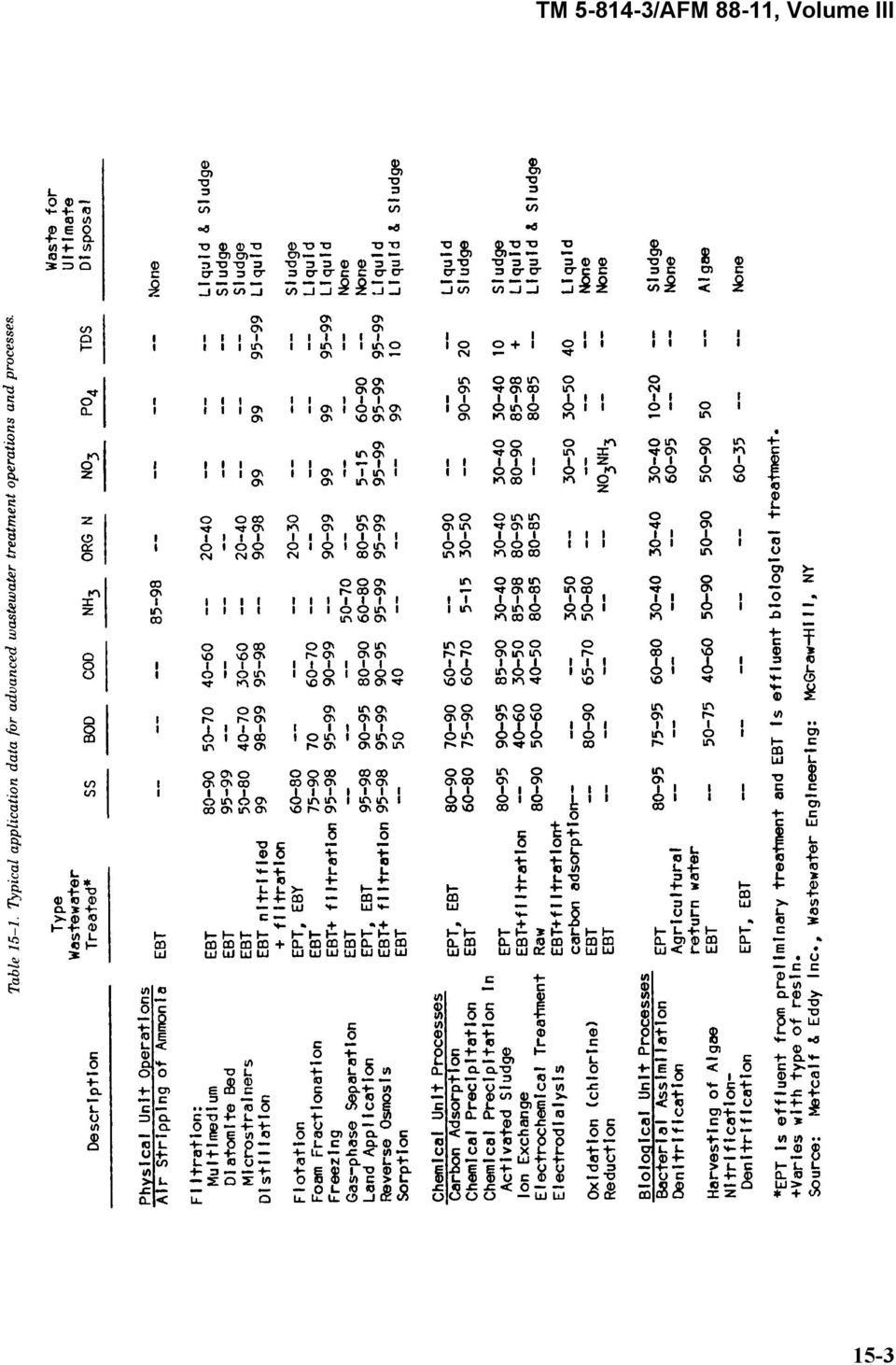
4 15-2. Polishing ponds. Wastewater treatment ponds may be used as a practical and economical method for upgrading existing secondary treatment facilities to obtain improved organic and suspended solids removal. Both aerobic and aerobic-anaerobic ponds can be used for this purpose. Ponds used for polishing purposes are subject to the same operating characteristics as those used for primary or secondary treatment, and the same precautionary design considerations must be applied. The design information and criteria presented in chapter 14 are applicable to design of polishing ponds. (See also Culp and Culp, 1971.) Post-aeration. This can be accomplished by either diffused, cascade, U-tube or mechanical aeration. Diffused aeration is carried out in tanks 9 to 15 feet deep and 10 to 50 feet wide (depth-to-width ratio is maintained at less than 2), with detention time of about 20 minutes. The maximum air requirement is approximately 0.15 cubic feet per gallon of wastewater treated. Mechanically aerated basins are 8 feet deep and require 15 to 50 square feet per aerator. Surface aeration is the most efficient mechanical aeration in terms of required horsepower (0.1 horsepower per 1,000 gallons of effluent). The drop required for cascade aeration in a stepped-weir structure or in a rapidly sloping channel filled with large rocks or concrete blocks will depend on the desired oxygen uptake: 2 feet of drop will be provided for each milligram per liter of dissolved oxygen increase required Microstraining. a. Description of process. A microstrainer consists of a rotating drum supporting a very fine, stainless steel or plastic screen. Wastewater is fed into the inside of the drum and filters radially outward through the screen, with the mat of solids accumulating on the screen inside the drum. The solids are flushed into a removal trough at the top of the drum by a pressurized backwash system. From this trough, the solids are returned to the head of the system. Process effluent wastewater can be used for the backwash. Table 15-2 provides performance data for several microscreen installations. 15-4

5 15-5
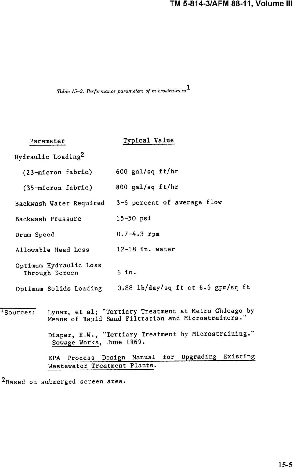
6 b. Design factors. Microstrainers will be designed on the basis of not exceeding 10.0 gallons per minute per square foot of submerged screen area at design maximum flow. Multiple units will be provided and all units will be protected against freezing. Typical opening sizes for microstraining fabrics are, 23, 35 and 60 microns (respective number of openings per square inch being 165,000, 80,000 and 60,000). With the 23- micron screen fabric, the microstrainer can be credited for 75 percent solids removal; 60 precent removal is achievable using the 35-micron fabric. Maximum solids loading for microstraining of activated sludge effluent is 0.88 pounds per day per square foot at a hydraulic loading of 6.6 gallons per minute per square foot. Table 15-3 presents typical power and space requirements for microscreens. c. Advantage and efficiency. An advantage of microstraining is the relatively low head loss (between 12 and 18 inches, with a 6-inch limit across a single screen). The efficiency of a microstrainer is determined by the hydraulic and solids loadings as well as by the filtering characteristics of the influent. Microstrainers will not remove colloidal material or small (micron size) algae. Microstrainers are also adversely affected by fluctuations in influent composition and quality. d. Hydraulic control. Hydraulic control of microscreening units is effected by varying the drum speed in proportion to the differential head across the screen. The controller is commonly set to give a peripheral drum speed of 15 feet per minute at 3 inches differential and 125 to 150 feet per minute at 6 inches. In addition, backwash flow rate and pressure may be increased when the differential reaches a given level. The operating drum submergence is related to the effluent water level and head loss through the fabric. The minimum drum submergence value for a given installation is the level of liquid inside the drum when there is no flow over the effluent weir. The maximum drum submergence is fixed by a bypass weir, which permits flows in excess of unit capacity to be bypassed; at maximum submergence, the maximum drum differential should never exceed 15 inches. Effluent and bypass weirs should be designed as follows: Select drum submergence level (70 to 75 percent of drum diameter) for no flow over the effluent weir; Locate top of effluent weir at selected submergence level; Determine maximum flow rate; Size effluent weir to limit liquid depth in effluent chamber above the weir to 3 inches at the maximum flow rate; Position the bypass weir 9 to 11 inches above effluent weir (3 inch head on effluent weir maximum flow plus 6 to 8 inch differential on drum at maximum drum speed and maximum flow); Size bypass weir length to prevent the level above effluent wire flow exceeding 12 to 18 inches at peak maximum flow or overflowing the top of the backwash collection hopper. 15-6

7 e. Backwashing. Backwash jets are directed against the outside of the microscreen drum as it passes the highest point in its rotation. About half the flow penetrates the fabric, dislodging the mat of solids formed on the inside. A hopper inside the drum receives the flushed-off solids. The hopper is positioned to compensate for the trajectory that the solids follow at normal drum peripheral velocities. Microscreen effluent is usually used for Backwashing. Straining is required to avoid clogging of backwash nozzles. The inline strainers used for this purpose will require periodic cleaning; the frequency of cleaning will be determined by the quality of the backwash water. (1) Sytems. The backwash system used by Zurn employs two header pipes; one operates continuously at 20 pounds per square inch, while the other operates at pounds per square inch. Under normal operating conditions, these jets operate at 35 pounds per square inch. Once a day they are operated at 50 pounds per square inch for ½ hour to keep the jets free of slime buildup. Should this procedure fail to keep the jets clean, the pressure is raised to 55 pounds per square inch. At this pressure the spring-loaded jet mouth widens to allow for more effective cleaning. (2) High pressure. Backwash pressure can be increased to compensate for heavy solids loadings which require higher pressure for thorough cleaning. The superiority of the higher-pressure system is manifested by the following: (a) Operation at 50 pounds per square inch, as opposed to 15 pounds per square inch, increases the process flow capacity 30 percent. (b) Suspended solids concentration in the backwash can increase from 260 milligrams per liter at 15 pounds per square inch to 425 milligrams per liter at 50 pounds per square inch. (c) Water consumption of the jets as a percent of process effluent decreases from 5 percent at 15 pounds per square inch to 2 percent at 50 pounds per square inch. In general, backwash systems are operated at as low a pressure as possible consistent with successful cleaning. High-pressure operation incurs added system maintenance, particularly jet replacement, and is used only as needed. f. Supplemental cleaning. Over a period of time, screen fabrics may become clogged with algal and slime growths, oil, and grease. To prevent clogging, cleaning methods in addition to Backwashing are necessary. (1) Ultraviolet lamps. Th reduce clogging from algal and slime growth, the use of ultraviolet lamps placed in close proximity to the screening fabric and monthly removal of units from service to permit screen cleaning with a mild chlorine solution is recommended. While most literature sources say ultraviolet lamps are of value, one authority feels these lamps are uneconomical because they require frequent replacement. Zurn Industries claims that, because their screening fabric is completely bonded to the supporting material, crevices where algae become lodged are eliminated and Backwashing alone is sufficient to remove algal and associated slime growths. (2) Hot water. Where oil and grease are present, hot water and/or steam treatment can be used to remove these materials from the microscreens. Plastic screens with grease problems are cleaned monthly with hot water at 1200 Fahrenheit to prevent damage to the screen material. Downtime for cleaning may be up to 8 hours. g. Operation. In starting a microscreening unit, care should be taken to limit differential water levels across the fabric to normal design ranges of 2 to 3 inches. For example, while the drum is being filled, it should be kept rotating and the backwash water should be turned on as soon as possible. This is done to limit the formation of excessive differential heads across the screen which would stress the fabric during tank fillup. Leaving the drum standing in dirty water should be avoided because suspended matter on the inside screen face which is above the water level may dry and prove difficult to remove. For this reason, introducing unscreened waters, such as plant overloads, into the microscreen effluent compartment should also be avoided. If the unit is to be left standing for any length of time, the tank should be drained and the fabric cleaned to prevent clogging from drying solids. 15-7

8 15-5. Filtration. a. Basic design parameters. The basic parameters to consider are the following: Type and size of filter media; Depth of filter; Rate, duration and timing of backwash; Filter run duration; Filtration rate; and Type of chemical pretreatment dosage requirement. b. Coarse-media filtration. (1) General design consideration. Filter media size will influence filter performance; smaller media will achieve better suspended solids removal, but will involve increased pressure drop and head loss buildup. Therefore, a balance between removal efficiency and hydraulic loading rate must be attained. For sewage applications, coarser media, higher flow rates and longer filter runs will be used. Chemical treatment of the feed water may be necessary to improve effluent quality. (2) Media sizes and filtration rate. Coarse media particles must have an effective size of approximately 1.3 millimeters with a uniformity coefficient of approximately 1. Sand or anthracite coal may be used, with coal giving a poorer solids removal but producing less pressure drop. Refer to the EPA Process Design Manual for Suspended Solids Removal for additional information regarding media specification. The design application rate for coarse-media filters will be 5 gallons per minute per square foot at design maximum flow. (3) Effectivenness. Single-media, coarse sand filters will be credited with 60 percent removal of suspended solids when the sand media size is no greater than 1.0 millimeters and the flow rate is no greater than 4 gallons per minute per square foot. Biochemical oxygen demand removal efficiencies will be dependent on the biochemical oxygen demand fraction of the suspended solids that is removed since dissolved organic materials generally pass through the filter. c. Multi-media filtration. Multi-media filtration, as compared to single-media filtration, will provide better suspended solids removal with longer filter runs at higher flow rates. A 75 percent suspended solids removal efficiency with multi-media filtration will be an acceptable design allowance for a design application rate of 5 gallons per minute per square foot. Filter aids such as alum can be used to increase removal efficiency. An application rate of 6 gallons per minute per square foot at maximum design flow will be utilized for design. Typical design parameters for multi-media filtration processes are given in tables 15-4 and

9 d. Upflow filtration. Upflow filtration utilizes a pressurized wastewater feed with flows in the upward direc-tion. Upward flow overcomes the fine-to-coarse particle-size distribution disadvantage of single-media filters. The media used is sand on top of gravel, with some models containing a grate on top of the sand layer to keep it compacted during filtration. This type of filter will achieve an average suspended-solids removal of 85 per- cent and is capable of higher solids loading than conventional filters. The maximum design filtration rate will be 8 gallons per minute per square foot. Continuous upflow, air wash filters are also available. e. Filter washing. All filters, with the exception of the upflow type, will require a reverse flow or backwash rate of 15 gallons per minute per square foot. An increased application or forward wash rate of 25 gallons per minute per square foot will be used for upflow filters. The required design duration of the wash cycle will be 8 minutes. The source of wash water in sewage filtration applications will be filter effluent or chemically coagulated and settled effluent rather than secondary effluent to ensure that the filter wash supply will always be free of large quantities of suspended solids. A filter wash flow indicator should be included so that the operator can be sure that the desired wash rate is being maintained at all times. The wasted wash water must be reprocessed. Storage facilities will be provided with filter wash wastewater returning to process at a controlled rate not to exceed 15 percent of the inflow. Provisions must be made to store the incoming flow during the filter wash cycle or, if there are no parallel units, to increase the rate on the other filters during the washing cycle. Either mechanical surface wash equipment or air scouring facilities will be provided as part of the backwashing design considerations Activated carbon adsorption. Use of activated carbon adsorption will be based on carbon column studies performed on the waste with the type of carbon that is to be used in the operating process at the site proposed. a. Process configurations. (1) Downflow. When used in a downflow configuration, carbon adsorption beds will accomplish filtration as well as adsorption. This generally is an inefficient use of the activated carbon and will require frequent backwashing. When the feedwater suspended solids concentration is greater than 50 to 65 milligrams per liter, solids removal pretreatment must be provided. Downflow carbon adsorption processes operate at hydraulic loadings of 2 to 10 gallons per minute per square foot of column cross-section area. The columns must be maintained in an aerobic condition to prevent sulfide formation; this will be accomplished by maintaining dissolved oxygen levels in feed and backwashing waters. (2) Upflow. Upflow carbon adsorption can be operated in three different modes. At hydraulic loadings less than 2 gallons per minute per square foot, the carbon bed remains packed at the bottom of the column, providing filtration as well as adsorption. (This filtration can cause backwashing problems.) At hydraulic loadings of 4 to 7 gallons per minute per square foot, the carbon is partially expanded and suspended solids pass through the bed. At loadings greater than 7 gallons per minute per square foot, the carbon bed is lifted. Upflow carbon beds are usually operated in the expanded-bed or partially expanded-bed mode and normally require no backwashing. However, periodic backwashing is helpful in removing carbon fines. Post-filtration will be provided to remove suspended solids from the effluent. 15-9

10 (3) Pulsed bed. A "pulsed bed" is defined as an upflow carbon adsorption system where a layer of exhausted carbon is withdrawn from the bottom of the carbon bed, with a regenerated layer being added to the top of the bed. This technique approximates countercurrent operation and is a nearly-continuous process. (4) Gravity and pressurized flow. Gravity-flow systems have the advantage of eliminating the need for pumps and pressure vessels. The restricting factor in gravity flow is head loss. For this reason, pretreatment for suspended solids removal is required. Gravity-flow systems can either downflow or upflow. The upflow, expanded-bed configuration will facilitate maintenance of a constant head loss. Pressurized-flow systems will offer more flexibility in process design by operating at higher flow rates and over wider ranges of pressure drop. (5) Series and parallel arrangement. Carbon contacting beds can be arranged as single stages, independently operated; or as multi-stages, either in series or in parallel. Series configurations achieve more complete organic removal and will be used when carbon adsorption is required to remove 90 percent of the total plant organics. Economic studies indicate that two-stage series operation is least expensive in terms of operating costs. For lower levels of treatment, single-stage, parallel contactors staggered in their status of operation or degree of exhaustion can produce the desired product by blending of individual effluent. (6) Regeneration. Activated carbon is regenerated in a step heating process; refer to the EPA Process Design Manual for Carbon Adsorption for design details. Carbon regeneration systems include preliminary dewatering of the carbon slurry to a moisture content of 40 to 50 percent, heating in a multiple-hearth furnace to 1,500-1,700 degrees Fahrenheit, quenching of regenerated carbon, and recycle to contactors. The regeneration process requires 3,200 British thermal units for burning off the impurities and 1 pound steam per pound of regenerated carbon. Air pollution control equipment is required, usually an afterburner and a wet scrubber or bag filter. (7) Carbon transport. The carbon is usually transported within the system as a slurry at velocities between 2.5 and 10 feet per second. Lower velocities make the system vulnerable to solids deposition and higher velocities cause abrasion in pipes. Velocities of 3 to 4 feet per second, with 4 pounds water per pound of carbon (0.5 gallon water per pound carbon), are recommended. The carbon slurry can be stored before and after regenera-tion, or it can be transported directly to and from the contactors. The latter arrangement requires at least two spare contactors and is a significant cost factor in pressurized systems. (8) Backwashing. Backwashing frequency is determined by head loss buildup, with lower flow rates usually allowing less frequent backwash. Backwashing is supplemented by surface washing and air scouring, and the complete operation lasts 15 to 45 minutes. Backwashing should provide 30 to 50 percent bed expansion while consuming no more than 5 percent of normal feed rate (i.e., 15 to 20 gallons per minute per square foot). Effluent can be used for backwash and then returned to the primary treatment stage. b. Process design parameters. Where practical, carbon column studies should be conducted on the waste to be treated to determine the process design parameters. These studies should use the type of activated carbon that will be used in operating the full-scale plant. (1) Pretreatment. Pretreatment will be provided as necessary to keep the suspended solids concentrations below 50 milligrams per liter unless the carbon bed is to be used as a filter also. (2) Carbon size. The carbon will be 8x 30 mesh, granular carbon unless carbon column studies show a different size to be more effective. (3) Contact time. Contact time is the most important design factor affecting organics removal and should be determined empirically for the particular situation. Typical values range from 18 to 36 minutes. (4) Hydraulic loadings. Hydraulic loadings between 2 and 10 gallons per minute per square foot are acceptable; there appears to be little effect on organics removal in this range. The main consideration is with head loss buildup. Gravity-flow systems are limited to hydraulic loadings less than 4 gallons per minute per square foot

11 (5) Carbon quantities and adsorption capacity. Carbon requirements range from 250 pounds to 350 pounds of carbon per million gallons treated; 300 pounds per million gallons is the preferred value. The adsorption capacity of carbon is affected by several factors and should be determined experimentally for each particular wastewater to be treated. Factors which influence adsorption include surface area, nature of the material to be adsorbed (adsorbate), ph, temperature, nature of carbon (adsorbent), and complexity of material to be adsorbed. The adsorption capacity of carbon per cycle usually ranges from 0.25 to 0.87 pounds COD removed per pound of carbon applied. Th obtain guidance regarding the selection of the type of activated carbon to be used in bench-scale or pilot-scale studies, refer to chapter 4 of the EPA Process Design Manual for Carbon Adsorption. c. Equipment. The effluent quality requirement will deterimine the required contact time and this in turn will set the approximate total carbon volume. The hydraulic loading will determin the total cross-sectional area and total carbon bed depth. The total bed depth can be divided between beds in series, and the total cross-sectional area can be divided into separate carbon beds in parallel. Vessel heights should provide for bed expansion of 50 percent. Contact tanks should have length-to-diameter ratio of between 0.75 and 2.0, with carbon depth usually greater than 10 feet. The tanks should be constructed of concrete or lined carbon steel. Typical coating materials range from a painted, coal tar epoxy to laminated rubber linings. The carbon transport system must be designed to resist the abrasiveness of carbon slurry. More specific design details can be obtained from the EPA Process Design Manual for Carbon Adsorption and from equipment manufacturers Phosphorus removal. 1. General approaches. Mineral addition and lime addition are the principal methods for in-plant removal of phosphorus from wastewater. The most commonly used of these metal salts are: alum, a hydrated aluminum sulfate (Al SO ).18 H 0); sodium aluminate (Na O.Al O ); ferric sulfate (Fe (SO ) ); ferrous sulfate (FeSO ); ferric chloride (FeCl ); and ferrous chloride (FeCl ). Mineral addition is usually followed by anionic polymer addition, which aids flocculation; the ph may require adjustment depending on the particular process. In lime addition, phosphorus removal is attained through the chemical precipitation of hydroxyapatite, Ca OH (PO ). When designing the phosphorus removal system, consideration must be given to the phosphorus levels in the system effluent suspended solids. Additional information may be found in the EPA Process Design Manual for Phosphorous Removal. b. Mineral addition using aluminum. (1) Aluminum requirements. The theoretical requirement for aluminum (Al) in the precipitation process is a mole ratio of aluminum to phosphorus of 1:1. Actual case histories have indicated considerably higher (2:1) than stoichiometeric quantities of aluminum are needed to meet phosphorus removal objectives. Alum, Al 2(SO 4) 3.18H2O, is the aluminum additive most frequently used, with sodium aluminate being substituted when alum addition would force the ph too low for other treatment processes. The theoretical weight ratio of alum to aluminum is 11:1 and in practice alum weight ratios in the range of 13:1 to 22:1 (depending on the degree of removal desired) have been needed. For higher removal efficiencies, the Al:P ratio must be increased. Table 15-6 lists the Al:P (and Fe:P) ratios required for 75, 85 and 95 percent phosphorus removal. Laboratory, pilot plant, or full-scale trial runs are often necessary to determine the most effective mineral dosages. (2) Addition at primary treatment stage. In the primary treatment stage, the mineral is added directly to the raw sewage which is then mixed, adjusted for ph (if necessary), flocculated, and clarified. The mixing and flocculation are to be carried out in specially designed units, or within existing systems at 15-11

12 appropriate locations such as manholes, Parshall flumes or pre-aeration tanks. For maximum phosphorus removal, the mineral addition will be downstream of return streams such as digester supernatant. The required procedure for mineral addition at the primary stage is as follows: Add mineral to raw sewage and mix thoroughly; Add alkali (if necessary for ph adjustment) 10 seconds later; Allow reaction for at least 10 minutes; Add anionic polymer and flash mix for 20 to 60 seconds; Provide mechanical or air flocculation for 1 to 5 minutes; and Deliver flocculated wastewater to sedimentation units. The advantages of removing phosphorus at the primary stage are the flexibility of chemical feeding, the adequate detention times and mixing conditions available, the reduced suspended solids and biochemical oxygen demand loading on the ensuing secondary treatment stage, and the ease of process instrumentation. The principal disadvantage is that a significant portion of the phosphates is not in the orthophosphate form at the primary treatment stage and therefore does not precipitate easily. Mineral addition also causes increased solids production (1.5 to 2.0 times the weight of normal primary solids), and the solids density increases with increasing aluminum dosages. Solids increases attributable to aluminum addition are about 4 pounds per pound of aluminum added, up to stoichiometric proportions, after which the weight gain is less. The addition of alum to the primary stage generates large quantities of metal hydroxide sludge, which is difficult to dewater. Therefore, alum addition to the primary clarifier shall be implemented with prior approval from HQDA (CEEC-EB) WASH DC for Army projects and HQ USAF/LEEE WASH DC for Air Froce projects. (3) Addition at secondary treatment stage. The advantages of mineral addition to the activated sludge process are enhanced sludge removal properties, shorter residence times, more effective phosphorus removal because of sludge recycle, relatively small additional solids production (which improves sludge density and dewaterability), and flexibility to changing conditions. The extra solids production, however, does involve additional sludge handling just as when alum is added at the primary stage. Therefore, alum addition to the aeration basin shall only be implemented with prior approval from HQDA (CEEC-EB) WASH DC for Army projects and HQ USAF/LEEE WASH DC for Air Force projects. In the activated sludge process, the chemical is added near the discharge point(s) into the aeration basin(s). Mixing of the chemical and wastewater must occur in the basin but premature precipitation must be prevented. Phosphorus capture will occur primarily in the sedimentation units following aeration in the basin. For trickling filter plants, it has been demonstrated that precipitation in the final clarifier can be both effective and controllable, as per EPA Manual 670/ Orthophosphate predominates at this point and it precipitates readily; also, biodegradable detergents, which can interfere with precipitation, are largely absent. If underfiow solids from a dosed final clarifier are returned to the primary clarifier, it will result in unusually effective clarification there. If the operation is not done effectively, poorly treated effluent can escape into the receiving water. In order to allow for incorporating the advantages of chemical treatment in both the primary and secondary clarifiers, provisions for future installa-tion of chemical addition and mixing facilities will be provided at the primary clarifier. Facilities or provisions for mineral addition to both primary and secondary clarifiers will provide flexibility of operation. Chemical treatment in both clarifiers can then be used if experience shows it to be the most effective technique at the particular plant involved. Initially, equipment will be provided only at the secondary clarifier unless bench studies or pilot plant operations show a more effective performance at another location or show the necessity of chemical feed at the primary clarifier also. (a) ph. The optimum ph for precipitation by aluminum is about 6.0, which agrees with the operating ph range for activated sludge processes. While this makes phosphorus removal during activated sludge treatment very effective, it interferes slightly with nitrification, which has an optimum ph range of 7.0 to 8.0. When both nitrification and phosphorus removal are desired to be accomplished in a single process such as extended aeration, nutrient removal is effectively accomplished at a ph of about

13 (b) Velocity gradients. The velocity gradient will be determined using equation G values greater than 75 sec- will cause some floc disintegration and this is usually exceeded in typical aeration basins. To achieve better settling and therefore more effective phosphorus removal, gentle mixing will be provided toward the end of the aeration basin or in a flocculation chamber. (c) Weight ratio. For a combined chemical-biological phosphorus removal system, the weight ratio of the net volatile solids in the aeration basin to the aluminum added to it must exceed the Al:P weight ratio (i.e., not less than 3) to prevent the occurance of non-settleable suspended solids in the effluent from the aeration basin. The more biological solids produced from the system, the greater the aluminum dosage that can be used without effluent suspended solids problems. (d) Mineral precipitates. In general, sludges containing mineral precipitates of phosphorus are stable in sludge digestion and heat treatment. The phosphates, as well as the insoluble hydroxides of excess minerals, do not resolubilize and they have no detrimental effects on the digestion process. (4) Addition at final settling basin. At the final settling basin, phosphorus removal is very effective because most of the soluble phosphates are in the orthophosphate form, which is the easiest to precipitate. The general procedure for mineral addition is essentially the same as in the primary stage. A surface overflow rate of 500 gallons per day per square foot should be used to size the final settling basin. c. Mineral addition using iron. (1) Iron requirements. The theoretical requirement for iron in phosphorus precipitation in terms of mole ratio of iron to phosphorus (Fe:P) is 1:1 for the ferric ion and 3:2 for the ferrous ion. Actual plant results indicate that the mole ratio for the ferrous ion is closer to 1:1. With the same mole ratio for ferrous and ferric ions, the weight ratio (Fe:P) is 1.8:1. As with aluminum, however, experience has indicated that the weight ratios are higher. The optimum ph range for ferric iron precipitation of phosphorus is 4.5 to 5.0, and for ferrous iron about 8.0. Ferrous salts cause a lowering of ph and may necessitate addition of alkali; however, alkali addition is not necessary when there is a subsequent aeration step. (2) Effectiveness. Addition of ferric forms of iron tends to yield a fine, light floc which does not settle well, but subsequent addition of lime and/or a polymer aids flocculation and settling. Ferrous iron addition may present residual problems in that excess ferrous ions may not hydrolyze and settle out at a ph lower than 8.0; lime addition will raise the ph and alleviate this problem. Ferrous salts yield good results when oxygen is available, such as in the activated sludge process. Ferric and ferrous iron addition, together with lime or polymer flocculation aids, is particularly applicable to primary treatment without a subsequent activated sludge step because there is little effluent floc carryover. However; for military installations, it is preferred that chemical addition follow the biological reactor. d. Mineral addition treatment schemes. Pilot plant study and full-scale plant operation will determine the most effective and practical treatment scheme for a particular situation. This most often involves multiplepoint chemical addition with recycle of mineral sludges. In the case of trickling filter plants, mineral addition, with a split of about 20 percent at the primary stage and 80 percent at final clarification with sludge recycle from the final settler to the primary settler; provides very effective phosphorus removal and good clarification. When removal requirements permit 5 milligrams per liter or more of phosphorus in the effluent stream, required treatment will follow the trickling filter. For very high phosphorus removal efficiencies, multi-media filtration is added after secondary settling (see a. above)
 to prevent the occurance of non-settleable suspended solids in the effluent from the aeration basin.")
14 e. Mineral selection and dosages. (1) Cost and availability. The choice of minerals should be based on cost of materials, availability of materials, and process performance. Costs and availability will be determined for each particular situation. Aluminum and iron salts are in the same cost range, with aluminum salts somewhat more expensive. (2) Side effects of various minerals. Both aluminum and iron additives will produce soluble side products in the form of chlorides, sulfates, and sodium compounds, as well as some free acids and alkalis due to hydrolysis. These side products are seldom a serious problem, however, and can be controlled by adding only the proper amount of chemical and through the use of the automatic monitoring instrumentation. Alum and FeCl 3 are the most commonly used mineral salts, and both cause an alkalinity drop which can lower ph if the buffering capacity is not adequate. Iron tends to yield higher effluent residuals (around 6 milligrams per liter as Fe) than aluminum (less than 0.5 milligrams per liter as Al). Aluminum addition produces 30 to 50 percent less additional solids than iron additives, and the sludge has greater dewaterability and sludge density. Aluminate and alum produce about the same amount of sludge but the aluminate sludge is considerably less dense. Alum addition tends to produce better effluent clarity than does aluminate. (3) Determination of dosage. Mineral dosages will be determined by the weight ratios and, when applicable, by pilot plant and laboratory studies and full-scale plant test runs. Alum dosages are usually in the range of 150 to 250 milligrams per liter as Al 2(SO 4) 3.18H2O for an average influent phosphorus concentration of about 10 milligrams per liter. Typical iron dosages range from 10 to 25 milligrams per liter as Fe. These typical dosages will accomplish 80 to 90 percent phosphorus removal. Greater phosphorus removal (down to residuals less than 0.5 mg/l as P) can be obtained by using multi-media filtration techniques. Refer to the EPA Process Design Manual for Phosphorous Removal. f. Lime treatment. (1) Process description and conditions. Lime addition accomplishes phosphorus removal through the chemical precipitation of hydroxyapatite (Ca5OH(PO 4) 3). Although the solubility product theoretically determines the amount left in solution, the actual determining factor in removal efficiency is the efficiency of the clarifiers. The precipitation of phosphorus by lime requires a high alkalinity, with a ph of 11 being optimum. Therefore, the lime dosage is not a function of phosphate concentration, but rather it depends on the amount of lime necessary to attain the proper ph. This in turn is largely dependent on influent wastewater alkalinity, which is illustrated in figure Typically, a lime dosage of as much as 400 milligrams per liter as CaO will be necessary to attain a ph of

15 (2) Advantages of lime treatment. Phosphorus removal by lime addition has these advantages: no soluble side products; improved oil, grease and scum removal; less corrosion in sludge handling systems; and recovery of the lime. The disadvantage is that the high ph required for lime addition has a detrimental effect on any downstream biological treatment process, including activated sludge, trickling filters and sludge digestion. (3) Treatment configurations. Lime treatment can be either a single-stage or a two-stage process depending on the degree of phosphorus removal required and the alkalinity of the wastewater. A low alkalinity of about 150 milligrams per liter as CaCO will yield a poorly settleable floc. A high alkalinity 3 requires subse-quent recarbonation (CO contact) to lower the ph, which in turn causes CaCO to percipitate, 2 3 and requires a second stage to settle out the CaCO sludge and provide better clarification. A high alkalinity 3 (200 mg/l as CaCO ), on the other hand, will yield a good settling floc at a ph as low as 9.5, thus eliminating 3 the need for a second stage since the CaCO precipitate will come out in the first stage. This process will be 3 considered as an alternative where the use of mineral salts would not be satisfactory
 Treatment configurations. Lime treatment can be either a single-stage or a two-stage process depending on the degree of phosphorus removal required and the alkalinity of the wastewater.")
16 15-16 (4) Single-stage lime treatment. The general procedure for single stage treatment is as follows: (a) Add lime slurry to wastewater as needed to obtain a ph of 9.5 to 10.5 and provide rapid mixing for about 30 seconds. (b) Provide flocculation and sedimentation. (c) If recalcination is used, thicken the sludge to 8-20 percent solids, centrifuge to percent solids, and then recalcine to CaO and Ca(OH) 2. This is usually not economical for the typical military-size installation. (d) After sedimentation, recarbonate for about 15 minutes to obtain the ph necessary for subsequent treatment or discharge. (5) Two-stage lime treatment. For two-stage treatment, the procedure is as follows: (a) Add lime to wastewater as needed to obtain ph equal to and provide mixing for about 30 seconds. (b) Provide flocculation and settling (sludge can be recalcined as in single-stage). (c) Provide recarbonation for 5 to 15 minutes to obtain a ph of 9.5 to (d) Provide second stage settling (sludge recalcined as required). (e) Again recarbonate for about 15 minutes to obtain the ph required for following treatment or discharge. (6) Effectiveness. Lime addition at the primary treatment stage is effective in removing from 80 to 90 percent of phosphorus. It also reduces biochemical oxygen demand by 50 to 70 percent, suspended solids by 85 percent, nitrogen by about 25 percent, and coliforms by as much as 99.9 percent. However, the igh ph necessary for this type of treatment causes difficulties in downstream biological treatment processes. Neutralization (recarbonation) may be required before biological treatment. Primary lime treatment will reduce the organic load on the secondary treatment stage and will reduce secondary sludge by almost half; the primary sludge, however, will increase about threefold. With lime treatment in the primary treatment stage, recalcination is often impractical because CaCo3 may not precipitate in sufficient quantities. A more effective and flexible technique is lime addition as a separate stage after secondary treatment. The advantages of this are the flexibility of operation and the backup function of the secondary system. Either single-stage or two-stage lime treatment can be used; however, two-stage treatment is preferred becaue it produces a better clarified effluent, has more lime recovery potential, and provides higher phosphorus removal efficiencies. The mixing, flocculation and settling units can be separate or integrated units. The integratedtype unit (upflow clarifier) works well but sludge blanket problems are encountered. Integrated units that work without sludge blankets and separate units are recommended. (7) Lime addition treatment schemes. Lime addition in the primary treatment can make use of existing process units, or separate units can be used. Modifications such as sludge recycle to the flocculation chamber and polymer addition improve settleability of the sludge and thereby improve phosphorus removal efficiency. Mineral addition can also be used (after primary treatment with lime) to improve overall phosphorus removal efficiency. For additional information refer to the EPA Process Design Manual for Phosphorous Remova. (8) Performance and dosage criteria. The lime requirement can vary over a wide range, depending on operating ph and water composition. Alkalinity affects the lime dose, as can calcium hardness. One part by weight of CaO can react with from 0.89 to 1.79 parts of bicarbonate alkalinity (expressed as CaCo 3); the lower value applying to very soft waters and the higher value to very hard waters. In addition to the reaction of lime with hardness, other competing reactions occur in lime treatment of wastewater. Also, there may be incomplete reaction of the lime. These complications make calculation of lime dose difficult; consequently, determination of lime dose is largely empirical. Some approximate values are given in the U.S. EPA Process Design Manual for Phosphorous Removal. The lime dose will usually be in the range of 300 to 400 milligrams per liter as CaO for two-stage treatment, and from 150 to 200 milligrams per liter where singlestage treat-ment is satisfactory.
 After sedimentation, recarbonate for about 15 minutes to obtain the ph necessary for subsequent treatment or discharge.")
17 (9) Recarbonation. This subject is discussed in detail in the EPA Process Design Manual for Phosphorous Removal Land application Systems. a. Background. The use of land and biomass growth upon and within the soil has a long and interesting history. This history, as well as a much more detailed treatment of land application of wastewaters is covered in EPA 625/ It should be noted that this manual is intended to be supplemented by the U.S. EPA manual for detailed design criteria. This has been done because of the broad site-specific design conditions that exist for land application systems. b. Health hazards and regulatory limitations. Because land treatment of wastewater entails a higher risk than other treatment processes of introducing pathogenic micro-organisms and toxic chemicals into groundwater and surface water, land treatment system design must carefully consider all possible means to prevent water supply contamination. Additionally, state and local health regulations often dictate land treatment process design criteria. Therefore, these regulations must be consulted early in the design phase and frequently throughout construction and operation to ensure consistent compliance. c. Treatment capabilities and objectives. Land treatment of domestic wastewater which has undergone secondary treatment and sludges from wastewater treatment plants may involve one of the following modes (Land treatment of wastewater after primary treatment is acceptable for isolated locations with restricted access when limited to crops which are not for direct human consumption.): Slow rate filtration; Rapid infiltration; Overland flow; Use of wetlands; and Subsurface incorporation. Two methods of land treatment apply to sludges: Composting and land spreading; and Subsurface incorporation. d. Slow rate processes. Slow rate processes essentially mean irrigation of crops, grassland or forest land based upon the demand of the vegetation. Typical application methods involve pipeline to row crops, surface distribution along furrows and ridges on the contour, sprinkler irrigation, or drip irrigation. Sprinklers and drip irrigation require that wastewater is quite free of solid suspended matter In arid to semi-arid areas, utilization of such wastewaters-even if only to recreational areas on a military compound-should be seriously considered both for conservation and to improve local aesthetics. e. Rapid infiltration. Rapid infiltration, often called "infiltration percolation, involves almost complete saturation of the soil column and potentially also the rock beneath. A thick, sandy regolith with low water table is required. Fresh water wells, well points and springs must be sufficiently far away as to not receive contamination. Often the object is to renovate water and to recapture the effluent again with special wells or underdrains for re-use in cooling or irrigation. Rapid infiltration may often be used to prevent the intrusion of saline water on an atoll or sandy coastal plain site. Although vegetation utilization is not planned for rapid infiltration systems, studies have shown that use of deep rooted plants, an active root and humus mat, and tolerant vegetation will much improve the quality of the recovered water. Vegetation must be carefully selected and, of course, some water will be lost to evapotranspiration and to production of biomass but the "living filter" will produce excellent quality water beneath the surface. (See D Itri et al., 1982.) f. Overland flow. This process involves a surface phenomena and depends strongly on vegetation and the myriad organisms in the humus layer of a sloped field. Wastewater is applied over the upper reaches of sloped terraces carefully constructed to match the contour of the land. Runoff after surface flow is collected in ditches. Application may be from linear pipeline sprayers, plastic trickle irrigators, or using rotating sprinklers. Overland flow could be used in forested land or to produce forage. Like the bio-filter concept, such systems not only remove suspended solids, kill pathogens and lower biochemical oxygen demand, but dramatically lower levels of nitrogen and phosphorus. (See D'Itri et al., 1984.) 15-17

18 g. Natural wetlands. Although true wetlands occupy only 3 percent of U.S. land surface, these areas offer great potential for recharging water tables and refurbishing wastewaters. Purposeful utilization of the ecologically complex habitats is new to modern man, who began to recognize around 1970 that fresh and salt water marshes, swamps, peat bogs, cypress domes, and strands could provide excellent, very inexpensive treatment. With proper system management and design, wetlands can treat wastewater without damaging the existing ecology; in fact, nutrient addition can enhance productivity and increase wildlife and overall aesthetic value. During cold periods, wetlands cannot handle discharges; therefore, storage in lagoons in necessary. Loading capacity has been estimated at about 40 persons per acre. Artifical wetlands have been constructed on sandy soil, using impervious plastic liner. Others have been made of less pervious silt and lined with clay. Peat bogs have been very successfully used in Minnesota and in Europe. In deep swamps-natural or artificial-water hyacinth, duckweed, wolffia and other aquatic plants have been used to remove nutrients o from wastewater. Limitations of such vegetational techniques have been placed at 35 N latitude. (See Sanks and Asano, 1976.) h. Subsurface application. Basically, the subsurface systems involve either soil mounds or subsurface filters (chap 6). Such systems ae used wehre adverse soil conditions exist, such as high water table, relatively impermeable clay-rich soils, or shallow bedrock. i. Composting of sludge. Where sufficient, inexpensive biomass is available (such as bark, wood chips, sawdust or other agricultural wastes), sewage may be directly mixed with organic matter and composted in open windrows or in a ventilated building. Such processes require a great deal of biomass, but the biomass may be dried in the sun with mechanical turning and then re-used to soak up more sewage. This systems may be used only if flows are small. Composting has most successfully been used on sludges from any of the unit operations discussed in this manual. Composting techniques were developed in China and India in ancient times, rediscovered in Europe in the 1800s, and recently have been utilized in the U.S. (Singley et al, 1982; Borchardt et al., 1981; Parr et al., 1982.) (1) Moisture control. Sludges may be composted without addition of organic matter but are generally too moist. Some bulky organic matter such as the organic portion of solid waste should be used to blend with the sludge and chipped media to entrain air and soak up moisture. Moisture content should be kept at around percent. (2) Techniques. The easiest and least expensive composting technique involves using partially dried, recycled compost, some new "bulking agent, and sludge mixed with a front-end loader or with mechanical mixers to the correct moisture content. The compost is then windrowed and turned "inside-out, outside-in several times at about one month intervals. An even simpler technique involves collecting leaves or other biomass during the year, piling the bulking agent in windrows, and pouring sludge into a depression shoveled along the length of the windrow. Such simple techniques and a six-month curing period will assure sufficient pathogen kill to allow use of the compost on military base shrubs, lawns or parks. A more elaborate scheme has been developed at Beltsville by USDA. In this system, blowers, aeration pipes and, usually, a roofed building allow mroe rapid "curing;; and a more continuous sludge processing. By this system, about 2.5 dry tons of sludge may be composted per acre, including space for the building, office, runoff control and adequate landscaping. Before any composting technique is used, a belt of trees should be established surrounding the work area for odor control (which in proper composting is minimal), dust dampening and seclusion. Partially finished compost combined with fresh sludge has been treated with earthworms, which stabilize compost even more rapidly. Earthworms may be removed from the compost by drum screening; but on military posts, their main function would be to speed up sludge stabilization and produce an easily handled, granular soil amendment from what had previously been a noxious slurry

19 j. Land spreading of sludges. Soil biota are capable of stabilizing most organic wastes, including oily sludges. Today, only about 25 percent of sludges are spread on land; even less are composted. However, the organic materials in sludges are beneficial in restoring fertility to soils disturbed by mining, gravel operations or poor agricultural practices. There are, however, some major limitations. Concentrated sludges (if not composted or otherwise stabilized) placed on land should be immediately covered to prevent odor production and insect breeding.. Sludges can be sliced or injected into soil or into stubble, using special equipment. Deep snow and deep frost will stop land spreading operations. Although heavy metals concentrations in some city or industrial sludges hae prevented their agricultural use, this limitation should not apply to waste sludges on military posts. Particularly useful for design of sludge land disposal is EPA Report 625/ (See also Seabloom et al., 1978.) Nitrification. + a. Process description. Nitrification occurs in two steps: first NH 4 is converted to NO2G by Nitrosomonas bacteria; then the NO2 G is converted to NO3G by Nitrobacter bacteria. This process is limited by the relatively slow growth rate of Nitrosomonas. The following discussion is mainly applicable to activated sludge processes and nitrification. Additional information may be found in EPA Process Design Manual for Nitrogen Control. b. Single-stage nitrification. When nitrification utilizing the activated sludge process is designed as a single stage, a longer detention time (12 to 24 hours as compared with the usual 2 to 8 hours) is necessary in the aeration basin in order to provide an effective microbial population. This is interpreted in terms of "mean solids residence time (SRT), which is defined as the amount of mixed-liquor, volatile suspended solids under aeration (in pounds) divided by the sum of suspended solids wasted and suspended solids lost in the effluent (in pounds per day). The mean solids residence time will be maintained at 10 to 20 days or longer, depending on the temperature; in terms of hydraulic detention time, 12 to 24 hours is typical. Temperature o has a significant effect on the nitrification reaction rate, which approximately doubles for every 10 C rise in o o temperature between 6 C and 25 C. A minimum dissolved oxygen level of 1.0 milligrams per liter is sufficient for nitrification. However, since dissolved oxygen concentration is a critical parameter, the aeration system will be designed to provide a residual dissolved oxygen of 2.0 milligrams per liter and ph 8.5, using lime addition if necessary. The optimum ph has been reported to be 8.4. Lime requirements will vary with the temperature and must be determined for each case. Nitrification consumes approximately 7.5 milligrams per liter of alkalinity per milligram per liter ammonia nitrogen oxidized. (1) Effect of toxic substances. Nitrification can be inhibited by certain toxic substances, such as halogen-substituted phenolic compounds, thiourea and its derivatives, halogenated solvents, heavy metals, cyanides, phenol, and cresol. These, however, are usually associated with industrial wastes. (Table 10-4 gives information on materials that inhibit nitrification.) (2) Design criteria for single-stage nitrification in activated sludge, extended aeration processes. The design of single-stage nitrification systems will provide for: (a) Increased aeration tank capacity and additional aeration to maintain dissolved oxygen level at 2.0 milligrams per liter; (b) A hydraulic detention time of 12 to 24 hours; (c) Sludge handling equipment suited to light, poorly compacted sludge, with recycle capacity of 150 percent of average flow; (d) Food-to-micro-organism ratio of less than 0.25 pounds biochemical oxygen demand per pound mixed liquor, volatile suspended solids; (e) Sludge retention time during winter conditions in excess of 20 days; and (f) Lime feeding equipment to provide alkalinity at a rate of 7.5 milligrams per liter per milligram per liter of ammonia oxidized, and a ph between 8.0 and

20 c. Separate-stage nitrification. Separate-stage nitrification simply separates the nitrification process from the activated sludge process. A typical system is illustrated in figure The main advantage to this system is that it allows individual optimization of the activated sludge and nitrification processes in terms of hydraulic and organic loadings. The relationship between ammonia removal rate and mixed liquor, volatile suspended solids concentration is shown in figure There is little sludge waste in the separate nitrification system and total sludge recycle is to be used. Detention time will be from 3 to 5 hours, based on influent flow with clarifier overflow rates between 500 and 800 gallons per day per square foot. Diffused air will be supplied at approximately 1 standard cubic foot per minute per gallon of wastewater treated

Engineers Edge, LLC PDH & Professional Training
 510 N. Crosslane Rd. Monroe, Georgia 30656 (770) 266-6915 fax (678) 643-1758 Engineers Edge, LLC PDH & Professional Training Copyright, All Rights Reserved Engineers Edge, LLC An Introduction to Advanced
CHAPTER 8 UPGRADING EXISTING TREATMENT FACILITIES
 CHAPTER 8 UPGRADING EXISTING TREATMENT FACILITIES 8-1. General. Upgrading of wastewater treatment plants may be required to handle increased hydraulic and organic loadings to meet existing effluent quality
WASTEWATER TREATMENT OBJECTIVES
 WASTEWATER TREATMENT OBJECTIVES The student will do the following: 1. Define wastewater and list components of wastewater. 2. Describe the function of a wastewater treatment plant. 3. Create a wastewater
 IMPACT OF CHEMICALS ADDITION IN WATER/WASTEWATER TREATMENT ON TDS CONCENTRATION AND SLUDGE GENERATION Jurek Patoczka, PhD, PE Hatch Mott MacDonald 27 Bleeker Str., Millburn, NJ 07041 (973) 912 2541 jurek.patoczka@hatchmott.com
Wastewater Nutrient Removal
 Wastewater Nutrient Removal An overview of phosphorus and nitrogen removal strategies Presented by: William E. Brown, P.E. Peter C. Atherton, P.E. Why are nutrients an issue in the environment? Stimulates
DESCRIPTION OF STORMWATER STRUCTURAL CONTROLS IN MS4 PERMITS
 DESCRIPTION OF STORMWATER STRUCTURAL CONTROLS IN MS4 PERMITS Phase I MS4 permits require continuous updating of the stormwater system inventory owned and operated by the MS4. They also include inspection
GUIDELINES FOR LEACHATE CONTROL
 GUIDELINES FOR LEACHATE CONTROL The term leachate refers to liquids that migrate from the waste carrying dissolved or suspended contaminants. Leachate results from precipitation entering the landfill and
Coagulation and Flocculation
 Coagulation and Flocculation Groundwater and surface water contain both dissolved and suspended particles. Coagulation and flocculation are used to separate the suspended solids portion from the water.
Chemistry at Work. How Chemistry is used in the Water Service
 Chemistry at Work How Chemistry is used in the Water Service WATER TREATMENT Everyday, more than 100 water treatment works in Northern Ireland put approximately 680 million litres of water into the supply
Cambridge Wastewater Treatment Facility
 Cambridge Wastewater Treatment Facility Emergency Situations If you have a water or sewer emergency that relates to the City s utility system call the Public Works office at 763-689-1800 on normal working
WISCONSIN WASTEWATER OPERATORS ASSOCIATION
 Integrity. People. Knowledge. WISCONSIN WASTEWATER OPERATORS ASSOCIATION ANNUAL CONFERENCE GREEN BAY Resources. MEETING LOW LEVEL PHOSPHORUS LIMITS BY CHEMICAL ADDITION WHAT IS PHOSPHORUS Atomic # 15 Electron
Removing Heavy Metals from Wastewater
 Removing Heavy Metals from Wastewater Engineering Research Center Report David M. Ayres Allen P. Davis Paul M. Gietka August 1994 1 2 Removing Heavy Metals From Wastewater Introduction This manual provides
WASTE WATER TREATMENT SYSTEM (OPERATING MANUALS )
") Page 1 of 76 1.0 PURPOSE The purpose of the Wastewater Treatment System is to remove contaminates from plant wastewater so that it may be sent to the Final Plant Effluent Tank and eventually discharged
Page 1 of 76 1.0 PURPOSE The purpose of the Wastewater Treatment System is to remove contaminates from plant wastewater so that it may be sent to the Final Plant Effluent Tank and eventually discharged
Ion Exchange Softening
 Ion Exchange Softening Ion-exchange is used extensively in small water systems and individual homes. Ion-exchange resin, (zeolite) exchanges one ion from the water being treated for another ion that is
Facility Classification Standards
 Facility Classification Standards Approval Date: April 3, 2009 Effective Date: April 3, 2009 Approved By: Nancy Vanstone, Deputy Minister Version Control: Replaces Facility Classification Standards dated
Environmental Technology March/April 1998
 Treating Metal Finishing Wastewater Sultan I. Amer, Ph.D. AQUACHEM INC. Environmental Technology March/April 1998 Wastewater from metal finishing industries contains high concentrations of contaminants
SYNERGISTIC APPLICATION OF ADVANCED PRIMARY AND SECONDARY WASTEWATER TREATMENT SYSTEMS
 SYNERGISTIC APPLICATION OF ADVANCED PRIMARY AND SECONDARY WASTEWATER TREATMENT SYSTEMS Published in Water and Waste Digest membrane issue, November 2008 Miroslav Colic; Chief Scientist, Clean Water Technology
Iron and Manganese BACTERIA AND IRON AND MANGANESE
 Iron and Manganese Iron and manganese control is the most common type of municipal water treatment in Minnesota. Iron and manganese occur naturally in groundwater. Neither element causes adverse heath
A HOMEOWNERS GUIDE ON-SITE SEWAGE MANAGEMENT SYSTEMS
 GEORGIA DEPARTMENT OF HUMAN RESOURCES ENVIRONMENTAL HEALTH SECTION A HOMEOWNERS GUIDE TO ON-SITE SEWAGE MANAGEMENT SYSTEMS March 12, 2002 WHAT IS AN ON-SITE SEWAGE MANAGEMENT SYSTEM An on-site sewage management
Description of the Water Conserv II Facility
 Description of the Water Conserv II Facility Introduction The Water Conserv II (WCII) Water Reclamation Facility provides service to a majority of the southwest section of Orlando. The WCII facility has
Well Water Iron Removal Using Quantum DMI-65 Granular Filter Media
 Well Water Iron Removal Using Quantum DMI-65 Granular Filter Media ASME Research Committee Power Plant and Environmental Chemistry Overland Park, Kansas April 2-4, 2007 Prepared by: W. H. Stroman Primary
How To Remove Iron From Water
 ISR IRON REMOVAL MEDIA Description INDION ISR is a special media designed to provide excellent catalytic properties to remove dissolved iron from ground water. INDION ISR is an insoluble media which oxidizes
Iron and manganese are two similar elements
 L-5451 2-04 Drinking Water Problems: Iron and Manganese Mark L. McFarland, Associate Professor and Extension Soil Fertility Specialist Monty C. Dozier, Assistant Professor and Extension Water Resources
Appendix B: Water Treatment Scenarios from AMD Treat
 Appendix B: Water Treatment Scenarios from AMD Treat 103 of 104 Jeddo Tunnel Abandoned Mine Drainage Passive vs. Active Treatment Cost Estimates Provided by Office of Surface Mining AMD Treat Software
Residuals Management Somersworth Drinking Water Treatment Facility. Ian Rohrbacher, Treatment Operator IV
 Residuals Management Somersworth Drinking Water Treatment Facility A HISTORICAL OVERVIEW OF SURFACE WATER TREATMENT RESIDUALS HANDLING Ian Rohrbacher, Treatment Operator IV Background We are a Grade III
Treatment options for hydrogen sulfide. Testing for hydrogen sulfide
 Sometimes hot water will have a sour smell, similar to that of an old damp rag. This smell often develops when the thermostat has been lowered to save energy or reduce the potential for scalding. Odor-causing
Water Softening for Hardness Removal. Hardness in Water. Methods of Removing Hardness 5/1/15. WTRG18 Water Softening and Hardness
 Water Softening for Removal 1 in Water High concentration of calcium (Ca2+) and magnesium (Mg2+) ions in water cause hardness Generally, water containing more than 100 mg/l of hardness expressed as calcium
SEPTIC SYSTEMS. 1. Building sewer connects the building plumbing to the septic tank.
 SEPTIC SYSTEMS Who Has A Septic System? Approximately 30 percent of Connecticut s population is served by on-site subsurface sewage disposal systems (a.k.a. septic systems). This means a large percentage
The formation of polluted mine water
 The formation of polluted mine water Abandoned Mine Drainage How it happens How we can fix it Bruce Golden Western PA Coalition for Abandoned Mine Reclamation What we ll cover Brief Discussion about Mining
Subject: Technical Letter 22 April 1977 Removal of Water Supply Contaminants -- Copper and Zinc
 STATE OF ILLINOIS Department of Registration and Education JOAN G. ANDERSON DIRECTOR. SPRINGFIELD BOARD OF NATURAL RESOURCES AND CONSERVATION JOAN G. ANDERSON CHAIRMAN BIOLOGY THOMAS PARK CHEMISTRY H.
Nutrient Removal at Wastewater Treatment Facilities. Nitrogen and Phosphorus. Gary M. Grey HydroQual, Inc. ggrey@hydroqual.com 201 529 5151 X 7167
 Nutrient Removal at Wastewater Treatment Facilities Nitrogen and Phosphorus Gary M. Grey HydroQual, Inc. ggrey@hydroqual.com 201 529 5151 X 7167 1 Agenda Nitrification and Denitrification Fundamentals
Town of New Castle Utility Department Introduction
 Town of New Castle Utility Department Introduction Town of New Castle Utility Department Mission Statement Our commitment is to ensure that our customers receive high quality water and wastewater treatment
POTW PHOSPHORUS REMOVAL PROCESSES
 POTW PHOSPHORUS REMOVAL PROCESSES Ohio Lake Erie Phosphorus Task Force - December 20, 2007 ROBERT M. BONNETT, PE Northeast Ohio Regional Sewer District OUTLINE SOURCES AND FORMS IN WASTEWATER TYPICAL POTW
Oasis Clearwater ENVIRONMENTAL SYSTEMS WASTEWATER TREATMENT ENGINEERS
 Oasis Clearwater ENVIRONMENTAL SYSTEMS WASTEWATER TREATMENT ENGINEERS The evolution continues in decentralised wastewater technology... The Process Decentralised wastewater treatment systems are defined
Water Water Treatment Plant Tour
 Water Water Treatment Plant Tour Don Rankin, Superintendent Topeka, KS 66606 785-368-3111 Tel 785-368-3825 FAX For a complete list of contacts with phone numbers, FAX numbers and email addresses, click
Hardness - Multivalent metal ions which will form precipitates with soaps. e.g. Ca 2+ + (soap) Ca(soap) 2 (s)
 Ca(soap) 2 (s)") Water Softening (Precipitation Softening) (3 rd DC 178; 4 th DC 235) 1. Introduction Hardness - Multivalent metal ions which will form precipitates with soaps. e.g. Ca 2+ + (soap) Ca(soap) 2 (s) Complexation
Water Softening (Precipitation Softening) (3 rd DC 178; 4 th DC 235) 1. Introduction Hardness - Multivalent metal ions which will form precipitates with soaps. e.g. Ca 2+ + (soap) Ca(soap) 2 (s) Complexation
Coagulation and Flocculation in Water and Wastewater Treatment
 W, A. R, Coagulation and Flocculation in Water and Wastewater Treatment Second Edition 02,/f John Bratby,» :.'; '5 s " - ' '! ' " ; i '. ', ' j ',... -,..,.,.-* ;, 0 61^/16*36 S "+ "J6 27 48 FAX 0 6151/16
CERTIFICATION TO OPERATE WATER AND WASTEWATER TREATMENT SYSTEMS APPLICATION INSTRUCTIONS
 COMMONWEALTH OF PENNSYLVANIA DEPARTMENT OF ENVIRONMENTAL PROTECTION STATE BOARD FOR CERTIFICATION OF WATER AND WASTEWATER SYSTEMS OPERATORS CERTIFICATION TO OPERATE WATER AND WASTEWATER TREATMENT SYSTEMS
Provided below is a description of the processes generating wastewater in a poultry plant and a typical pretreatment and full treatment system.
 II. PROCESS OVERVIEW Provided below is a description of the processes generating wastewater in a poultry plant and a typical pretreatment and full treatment system. II.1. Wastewater Generation A typical
REMOVAL OF PHOSPHATE FROM WASTEWATER USING LOW-COST ADSORBENTS
 International Journal of Engineering Inventions ISSN: 2278-7461, www.ijeijournal.com Volume 1, Issue 7 (October2012) PP: 44-50 REMOVAL OF PHOSPHATE FROM WASTEWATER USING LOW-COST ADSORBENTS Dr. C.R.Ramakrishnaiah
Phosphorus Removal. Wastewater Treatment
 Phosphorus Removal In Wastewater Treatment by Derek Shires (512) 940-2393 Derek.Shires@ett-inc.com Why do we care? Eutrophication of surface water - Especially reservoirs Maximum agronomic uptake - Limiting
A NOVEL ION-EXCHANGE/ELECTROCHEMICAL TECHNOLOGY FOR THE TREATMENT OF AMMONIA IN WASTEWATER
 A NOVEL ION-EXCHANGE/ELECTROCHEMICAL TECHNOLOGY FOR THE TREATMENT OF AMMONIA IN WASTEWATER ABSTRACT Leonard P. Seed, M.Sc., P.Eng., Enpar Technologies Inc. * Daren D. Yetman, A.Sc.T., Enpar Technologies
NUTRIENT REMOVAL FROM SECONDARY EFFLUENT BY ALUM FLOCCULATION AND LIME PRECIPITATION*
 University of Wisconsin Engineering Experiment Station Reprint Number 708 Int. J. Air Wat. Poll. Pergamon Press 1964. Vol. 8, pp. 487-500. Printed in Great Britain. NUTRIENT REMOVAL FROM SECONDARY EFFLUENT
Table 1.1: Typical Characteristics of Anaerobically Digested Wastewater
 Solar Detoxification of Distillery Waste Anil K. Rajvanshi and Nandini Nimbkar Nimbkar Agricultural Research Institute (NARI), P.O. Box 44, PHALTAN-415523, Maharashtra E-mail : nariphaltan@gmail.com Introduction
Glossary of Wastewater Terms
 Glossary of Wastewater Terms Activated Sludge Sludge that has undergone flocculation forming a bacterial culture typically carried out in tanks. Can be extended with aeration. Advanced Primary Treatment
Using Magnesium Hydroxide
 Industrial Wastewater Neutralization Using Magnesium Hydroxide May 15, 2012 Steve Leykauf, Presenter Discussion Topics What is Magnesium Hydroxide? Technical Benefits of Magnesium Hydroxide Economic Benefits
Module 16: The Activated Sludge Process - Part II Instructor Guide Answer Key
 Unit 1 Process Control Strategies Exercise Module 16: The Activated Sludge Process - Part II Instructor Guide Answer Key 1. What are the six key monitoring points within the activated sludge process? Ans:
City of Lakeland s Wetlands Treatment System An Overview
 An Overview In response to more stringent requirements for wastewater discharges in the early 1980 s, the City explored options for the advanced treatment required, with the Wetland Treatment System proving
CERTIFIED SEPTIC EVALUATION PREPARED FOR MATT HASHEM 1673 MT. MAJOR HWY, ALTON, NH 03810
 DATE: May 31, 2013 N.H. LICENSED DESIGNER OF SUBSURFACE DISPOSAL SYSTEMS 216 Hill Road Phone & Fax: 934-6206 Franklin, NH 03235 Cell: 393-3085 CERTIFIED SEPTIC EVALUATION PREPARED FOR MATT HASHEM 1673
ENVIRONMENTAL ISSUES IN THE RENDERING INDUSTRY. Gregory L. Sindt, P.E. Environmental Engineer Bolton and Menk, Inc.
 Summary ENVIRONMENTAL ISSUES IN THE RENDERING INDUSTRY Gregory L. Sindt, P.E. Environmental Engineer Bolton and Menk, Inc. The rendering industry has a significant positive impact on environmental quality.
Phosphorus Removal. P.F. Strom, 2006; do not copy without written permission.
 Phosphorus Removal Dr. Peter F. Strom, Professor Dept. of Environmental Sciences Cook College, Rutgers University 14 College Farm Road New Brunswick, NJ 08901-8551 (732) 932-8078; strom@aesop.rutgers.edu
Rehabilitation of Wastewater Treatment Plant of Sakhnin City in Israel by Using Advanced Technologies
 Rehabilitation of Wastewater Treatment Plant of Sakhnin City in Israel by Using Advanced Technologies Yasar Avsar 1, Hussein Tarabeah 2, Shlomo Kimchie 3, Izzet Ozturk 4, Hadi Naamneh 2 1 Yildiz Technical
During the past decade, the city of
 An Advanced Pollution Control Facility s Conversion to Four-Stage Bardenpho to Improve Biological Nitrogen Removal Timur Deniz, Thomas W. Friedrich, and John Milligan During the past decade, the city of
Phosphorus. Phosphorus Lake Whatcom Cooperative Management. www.ecy.wa.gov/programs/wq/nonpoint/phosphorus/phosphorusban.html
 Phosphorus Phosphorus Brochure Lake Whatcom Cooperative Management Reducing Phosphorus Website Washington State Department of Ecology www.ecy.wa.gov/programs/wq/nonpoint/phosphorus/phosphorusban.html Nutrients
PROPAK AquaBio Complete Water Restoration Systems
 PROPAK AquaBio Complete Water Restoration Systems Conserving natural resources and lowering operating expenses is no longer an option, it is a necessity. Water, sewer and discharge fees are continuing
THE MARSHALL STREET ADVANCED POLLUTION CONTROL FACILITY (CLEARWATER, FLORIDA) CONVERSION TO 4-STAGE BARDENPHO TO IMPROVE BIOLOGICAL NITROGEN REMOVAL
 CONVERSION TO 4-STAGE BARDENPHO TO IMPROVE BIOLOGICAL NITROGEN REMOVAL") THE MARSHALL STREET ADVANCED POLLUTION CONTROL FACILITY (CLEARWATER, FLORIDA) CONVERSION TO 4-STAGE BARDENPHO TO IMPROVE BIOLOGICAL NITROGEN REMOVAL ABSTRACT Timur Deniz, Ph.D., Thomas W. Friedrich, P.E.
THE MARSHALL STREET ADVANCED POLLUTION CONTROL FACILITY (CLEARWATER, FLORIDA) CONVERSION TO 4-STAGE BARDENPHO TO IMPROVE BIOLOGICAL NITROGEN REMOVAL ABSTRACT Timur Deniz, Ph.D., Thomas W. Friedrich, P.E.
Experts Review of Aerobic Treatment Unit Operation and Maintenance. Bruce Lesikar Texas AgriLife Extension Service
 Experts Review of Aerobic Treatment Unit Operation and Maintenance Bruce Lesikar Texas AgriLife Extension Service Overview Overview of Aerobic Treatment Units Installing for accessibility to system components
1.3 Wastewater and Ambient Water Quality
 1.3 Wastewater and Ambient Water Quality Applicability and Approach...25 General Liquid Effluent Quality...26 Discharge to Surface Water...26 Discharge to Sanitary Sewer Systems...26 Land Application of
AP ENVIRONMENTAL SCIENCE 2007 SCORING GUIDELINES
 AP ENVIRONMENTAL SCIENCE 2007 SCORING GUIDELINES Question 1 Read the Fremont Examiner article below and answer the questions that follow. (a) Identify ONE component of the sewage that is targeted for removal
Total Suspended Solids Total Dissolved Solids Hardness
 Total Suspended Solids (TSS) are solids in water that can be trapped by a filter. TSS can include a wide variety of material, such as silt, decaying plant and animal matter, industrial wastes, and sewage.
Corrosivity of Water Supplies
 WD-DWGB-3-4 2009 Corrosivity of Water Supplies What is meant by Corrosivity? Corrosive water can be defined as a condition of water quality which will dissolve metals from metallic plumbing at an excessive
This Questionnaire is divided into 8 sections referring to different capacity areas on the safe use of wastewater in agriculture:
 Annex - II Questionnaire to support the Capacity Development Needs Assessment In the framework of the Capacity Development Project on Safe Use of Wastewater 1 in Agriculture Phase I The Food and Agriculture
Development of Advanced Wastewater Treatment and Reclamation System
 14 Development of Advanced Wastewater Treatment and Reclamation System TAKESHI TERAZAKI *1 HOZUMI OTOZAI *2 KOSUKE SHIGIISHI *2 HIDEO SUZUKI *3 HIROSHI NAKASHOJI *4 HIROYUKI KAWAMOTO *5 Recycling and the
Wastewater Reuse. Typical treated wastewater is:
 Wastewater Reuse Most metal finishing industries have in-house wastewater treatment to economically dispose of the acids, alkali, oils, and dissolved metals in the rinse water and occasional tank solution
SUSTAINABLE URBAN DRAINAGE SYSTEMS
 overflow can lead into a permeable conveyance system to increase further the benefit and reduce the need for pipe systems. Pollutant removal rates have been shown to be high, with some pollutants being
for Sediment Removal desired levels. The filtered water then can be chemically treated to ensure its safety. Municipal water Preliminary settling
 Treating Water for Sediment Removal J.R. Miner Lakes, ponds, and streams are important sources of water for many farms, rural camps, and households as well as for many municipalities in Oregon. Even under
BASIC WATER TREATMENT OF STEAM BOILERS
 BASIC WATER TREATMENT OF STEAM BOILERS Steve Kenny and Dave Pope Chemco Water Technology Vancouver, WA This is a brief discussion on low-pressure steam boiler chemistry. It provides dry kiln boiler operators
Filtration. Filtration 1
 Filtration Filtration plays an important role in the natural treatment of groundwater as it percolates through the soil. It is also a major part of most water treatment. Groundwater that has been softened,
Septic System Care & Maintenance
 Septic System Care & Maintenance A User s Guide for Home/Cottage Owners Spring 2003 Preventing Septic Failure & Malfunction How many of us know how our septic system works, or think we know? We expect
Using composting beds to treat acidity in saline drain water
 Government of Western Australia Department of Water Using composting beds to treat acidity in saline drain water Introduction Acidic saline water is common in drains used to manage shallow saline watertables
Type of Sewer Systems. Solomon Seyoum
 Type of Sewer Systems Solomon Seyoum 0 Learning objectives Upon completion of this lecture, the participants will be able to differentiate between types of sewer systems and discuss different aspects of
RULE 8-8 - ORGANIC COMPOUNDS - WASTEWATER COLLECTION AND SEPARATION SYSTEMS
 BAY AREA AIR QUALITY MANAGEMENT DISTRICT RULE 8-8 - ORGANIC COMPOUNDS - WASTEWATER COLLECTION AND SEPARATION SYSTEMS (ADOPTED: January 17, 1979) (AMENDED: November 1, 1989; October 6, 1993; June 15, 1994;
Understanding and Living With Your Septic System
 Chapter 9 Understanding and Living With Your Septic System Rural versus urban sewage treatment One of the big difference between rural and city life is how sewage is dealt with. Cities usually have community
Characterizing Beauty Salon Wastewater for the Purpose of Regulating Onsite Disposal Systems
 Characterizing Beauty Salon Wastewater for the Purpose of Regulating Onsite Disposal Systems Fred Bowers 1,2, Ph.D. New Jersey Department of Environmental Protection Division of Water Quality August 14,
Detention Ponds. Detention Ponds. Detention Ponds. Detention Ponds. Detention Ponds. Detention Ponds. CIVL 1112 Detention Ponds - Part 1 1/12
 CIVL 1112 - Part 1 1/12 The water cycle, also known as the hydrologic cycle, describes the continuous movement of water on, above and below the surface of the Earth. The water cycle, also known as the
Homeowner s Guide to Maintaining a Sewage Treatment System
 Homeowner s Guide to Maintaining a Sewage Treatment System Warren County Combined Health District 416 South East Street Lebanon, OH 45036 513-695-1220 Sewage Treatment Systems Septic Tank and Soil Absorption
Alberta Onsite Wastewater Management Association Installer Training Program
 Alberta Onsite Wastewater Management Association Installer Training Program OWTS 100 Overview and Principles of Wastewater Treatment Systems Brief Review of All Types of Systems 1. Know the general principles
Hardness ions also interfere with many chemical processes such as chemical compounding and aqueous cleaners.
 Water Softeners Industrial Water Purification (800) CAL-WATER By Dave Peairs, Cal Water, Technical Director Rev: 06/08/2004 Before any discussion of water softeners, we must first define what hard water
Presented by Paul Krauth Utah DEQ. Salt Lake Countywide Watershed Symposium October 28-29, 2008
 Basic Nutrient Removal from Water Beta Edition Presented by Paul Krauth Utah DEQ Salt Lake Countywide Watershed Symposium October 28-29, 2008 Presentation Outline Salt Lake County waters / 303(d) listings
Indiana State Department of Health Construction Guidelines for Gravity and Flood-Dose Trench Onsite Systems
 Indiana State Department of Health Construction Guidelines for Gravity and Flood-Dose Trench Onsite Systems The septic tank-absorption field sewage treatment system is composed of two major elements; the
A Guide to Trouble-Free Cooling Towers
 A Guide to Trouble-Free Cooling Towers A basic understanding of cooling tower operation and maintenance will help keep a cooling water system running in top condition, year after year By David M. Suptic
Swamp Area Passive Treatment System Kettle Creek Watershed, Clinton County, PA
 Swamp AMD Chemistry Swamp Area Passive Treatment System Kettle Creek Watershed, Clinton County, PA A Technical Report for Trout Unlimited and the Kettle Creek Watershed Association Prepared by Hedin Environmental
Water Treatment. Session Objectives
 Water Treatment Session Objectives To demonstrate the need for treatment of surface waters and some groundwaters for drinking purposes. To introduce the concept of the multiple barrier principle and to
Water Treatment & Purification Chemicals
 Lime-Out Extra Water Treatment Cleaning Chemicals Dissolves tough lime, calcium & rust stains Non-abrasive thick jelly like liquid clings to vertical surfaces Cleans tubs, sinks, shower doors, dishwashers
CWD BALDWIN PLANT NEW RESIDUALS HANDLING SYSTEM
 CWD BALDWIN PLANT NEW RESIDUALS HANDLING SYSTEM OTCO Water Workshop March, 2011 Frank Woyma Plant Manager Nick Pizzi Vice-President EE&T ENVIRONMENTAL ENGINEERING & TECHNOLOGY, INC. Objectives Review the
Appendix 2-1. Sewage Treatment Process Options
 Appendix 2-1 Sewage Treatment Process Options Table of Contents Appendix 2-1 Sewage Treatment Process Options 1 Introduction...1 2 Chemically Enhanced Primary Treatment (CEPT) Processes...2 2.1 CEPT with
TREATMENT OF PHOSPHATE FERTILIZER PLANT WASTE WATER IN FLORIDA FOR DISCHARGE AND RE USE PURPOSES
 TREATMENT OF PHOSPHATE FERTILIZER PLANT WASTE WATER IN FLORIDA FOR DISCHARGE AND RE USE PURPOSES JOHN F. BOSSLER, SIEMENS Water Technologies Corp., Hoffman Estates, IL RONALD TRAVIS, SIEMENS Water Technologies
FERTIGATION. Lawrence J. Schwankl
 production FERTIGATION Lawrence J. Schwankl F ertigation is the injection of fertilizers through the irrigation system. Microirrigation systems are well-suited to fertigation because of their frequency
Looking after your Septic Tank System
 Looking after your Septic Tank System Name: Bought to you by Address: File this in your property file. 0800 TO FLUSH Call 0800 TO FLUSH 1 What do you know about your septic tank system? Just like your
Lance DeClue, REHS Environmental Health Specialist II County of San Diego Department of Environmental Health
 Lance DeClue, REHS Environmental Health Specialist II County of San Diego Department of Environmental Health Basic OWTS system design and function OWTS maintenance OWTS failures & repairs OWTS-STS (Supplemental
Minnesota. BMI Project No. M21.037315
 Wastewater Treatment Facility Plan City of Paynesville Minnesota BMI Project No. M21.037315 March 2009 TABLE OF CONTENTS EXECUTIVE SUMMARY... 1 A. GENERAL... 1 B. DESIGN PARAMETERS... 1 C. COST ESTIMATES...
ALL YOU NEED TO KNOW...
 ALL YOU NEED TO KNOW... What do you know about your septic tank system? For the purposes of this booklet, a septic tank system refers to any kind of on-site sewage management system including traditional
INFORMATION SHEET ORDER NO. R5-2011-XXXX TRIANGLE ROCK PRODUCTS, INC. FLORIN ROAD AGGREGATE PLANT SACRAMENTO COUNTY
 ORDER NO. R5-2011-XXXX INFORMATION SHEET Background Triangle Rock, Inc. (Discharger) submitted a Report of Waste Discharge (RWD) on 23 August 2010. The Discharger is expanding the mining operations at
Advanced Wastewater Treatment and Disposal Systems. Water and Wastewater Utility Operation and
 Advanced Wastewater Treatment and Disposal Systems Water and Wastewater Utility Operation and Management for Tribes Preliminary Treatment Primary Treatment Secondary Treatment Tertiary Treatment Disinfection
BMP #: Dry Wells / French Drains
 Structural BMP Criteria BMP #: Dry Wells / French Drains A Dry Well, or French Drain, is a variation on an Infiltration Trench that is designed to temporarily stores and infiltrate rooftop runoff. Key
Florida Department of Environmental Protection
 Florida Department of Environmental Protection Background Mobile vehicle and equipment washing involves washing at a location where vehicles are based (such as a trucking company, warehouse, bus station,
Feasibility study of crystallization process for water softening in a pellet reactor
 International A. H. Mahvi, Journal et al. of Environmental Science & Technology Feasibility study of crystallization... Vol. 1, No. 4, pp. 1-4, Winter 5 Feasibility study of crystallization process for
COD/BOD 5 Reduction with ROTAMAT Fine and Micro Screens
 COD/BOD 5 Reduction with ROTAMAT Fine and Micro Screens Removal of particulate material from wastewater Eco-efficient use of capital Water pollution control through maximum COD/BOD 5 reduction Service
WASTE WATER TREATMENT for surface treatment applications
 WASTE WATER TREATMENT for surface treatment applications Effluent an important cost factor Effluent cannot be avoided Water and compound are essential for vibratory mass finishing. During the finishing
Index. protection. excavated drop inlet protection (Temporary) 6.50.1 6.51.1. Block and gravel inlet Protection (Temporary) 6.52.1
 6.50.1 6.51.1. Block and gravel inlet Protection (Temporary) 6.52.1") 6 Index inlet protection excavated drop inlet protection (Temporary) 6.50.1 HARDWARE CLOTH AND GRAVEL INLET PROTECTION Block and gravel inlet Protection (Temporary) sod drop inlet protection ROCK DOUGHNUT
6 Index inlet protection excavated drop inlet protection (Temporary) 6.50.1 HARDWARE CLOTH AND GRAVEL INLET PROTECTION Block and gravel inlet Protection (Temporary) sod drop inlet protection ROCK DOUGHNUT