HYOSUNG MOTORS & MACHINERY INC. SERVICE MANUAL SERVICE MANUAL
|
|
|
- Rudolph Leonard
- 8 years ago
- Views:
Transcription
1 HYOSUNG MOTORS & MACHINERY INC. SERVICE MANUAL SERVICE MANUAL

2 FOREWORD GROUP INDEX This manual contains an introductory description on HYOSUNG / and procedures for its inspection/service and overhaul of its main components. Other information considered as generally known is not included. Read GENERAL INFORMATION section to familiarize yourself with outline of the vehicle and MAINTENANCE and other sections to use as a guide for proper inspection and service. This manual will help you know the vehicle better so that you can assure your customers of your optimum and quick service. This manual has been prepared on the basis of the latest specification at the time of publication. If modification has been made since then, difference may exist between the content of this manual and the actual vehicle. Illustrations in this manual are used to show the basic principles of operation and work procedures. They may not represent the actual vehicle exactly in detail. WARNING This manual is intended for those who have enough knowledge and skills for servicing HYOSUNG vehicles. Without such knowledge and skills, you should not attempt servicing by relying on this manual only. Instead, please contact your nearby authorized HYOSUNG motorcycle dealer. GENERAL INFORMATION 1 PERIODIC MAINTENANCE 2 ENGINE 3 FUEL SYSTEM 4 ELECTRICAL SYSTEM CHASSIS 5 6 SERVICING INFORMATION 7 HYOSUNG MOTORS & MACHINERY INC. COPYRIGHT HYOSUNG MOTORS & MACHINERY INC

3 HOW TO USE THIS MANUAL TO LOCATE WHAT YOU ARE LOOKING FOR: 1. The text of this manual is divided into sections. 2. As the title of these sections are listed on the previous page as GROUP INDEX, select the section where you are looking for. 3. Holding the manual as shown at the right will allow you to find the first page of the section easily. 4. On the first page of each section, its contents are listed. Find the item and page you need. COMPONENT PARTS Example: Front wheel

4 SYMBOL Listed in the table below are the symbols indicating instructions and other information necessary for servicing and meaning associated with them respectively. SYMBOL Torque control required. Data beside it indicates specified torque. Apply oil. Use engine oil unless otherwise specified. Apply SUPER GREASE A. Apply SILICONE GREASE. Apply MOLY PASTE. Apply BOND DEFINITION Apply SUPER GREASE C. SYMBOL Apply THREAD LOCK Apply or use brake fluid. Measure in voltage range. Measure in resistance range. Measure in current range. Use special tool. DEFINITION

5 NOTE Difference between photographs and actual motorcycles depends on the markets.

6 GENERAL INFORMATION CONTENTS INFORMATION LABELS 1-1 GENERAL PRECAUTIONS 1-1 SERIAL NUMBER LOCATION 1-3 FUEL AND OIL RECOMMENDATIONS 1-4 BREAK-IN PROCEDURES 1-5 CYLINDER CLASSIFICATION 1-5 EXTERIOR ILLUSTRATION 1-6 SPECIFICATIONS 1-8 1

7 1-1 GENERAL INFORMATION WARNING / CAUTION / NOTE Please read this manual and follow its instructions carefully. To emphasize special information, the symbol and the words WARNING, CAUTION and NOTE have special meanings. Pay special attention to the messages highlighted by these signal words. Please note, however, that the warning and cautions contained in this manual cannot possibly cover all potential hazards relating to the servicing, or lack of servicing, of the motorcycle. In addition to the WARNING and CAUTION stated, you must use good judgement and basic mechanical safety principles. If you are unsure about how to perform a particular service operation, ask a more experienced mechanic for advice. GENERAL PRECAUTIONS WARNING Indicates a potential hazard that could result in death or injury. CAUTION Indicates a potential hazard that could result in vehicle damage. NOTE Indicates special information to make maintenance easier or instructions cleaner. WARNING Proper service and repair procedures are important for the safety of the service machanic and the safety and reliability of the vehicle. When 2 or more persons work together, pay attention to the safety of each other. When it is necessary to run the engine indoors, make sure that exhaust gas is forced outdoors. When working with toxic or flammable materials, make sure that the area you work in is well-ventilated and that you follow all off the material manufacturer s instructions. Never use gasoline as a cleaning solvent. To avoid getting burned, do not touch the engine, engine oil or exhaust system during or for a while after engine operation. After servicing fuel, oil, exhaust or brake systems, check all lines and fittings related to the system for leaks.

8 GENERAL INFORMATION 1-2 WARNING If parts replacement is necessary, replace the parts with HYOSUNG Genuine Parts or their equivalent. When removing parts that are to be reused, keep them arranged in an orderly manner so that they may be reinstalled in the proper order and orientation. Be sure to use special tools when instructed. Make sure that all parts used in reassembly are clean, and also lubricated when specified. When use of a certain type of lubricant, bond, or sealant is specified, be sure to use the specified type. When removing the battery, disconnect the negative cable first and then positive cable. When reconnecting the battery, connect the positive cable first and then negative cable, and replace the terminal cover on the positive terminal. When performing service to electrical parts, if the service procedures do not require use of battery power, diconnect the negative cable at the battery. Tighten cylinder head and case bolts and nuts, beginning with larger diameter and ending with smaller diameter, from inside to outside diagonally, to the specified tightening torque. Whenever you remove oil seals, gaskets, packing, O-rings, locking washers, cotter pins, circlips, and certain other parts as specified, be sure to replace them with new ones. Also, before installing these new parts, be sure to remove any left over material from the mating surfaces. Never reuse a circlip. When installing a new circlip, take care not to expand the end gap larger than required to slip the circlip over the shaft. After installing a circlip, always ensure that it is completely seated in its groove and securely fitted. Do not use self-locking nuts a few times over. Use a torque wrench to tighten fasteners to the torque values when specified. Wipe off grease or oil if a thread is smeared with them. After reassembly, check parts for tightness and operation. WARNING To protect environment, do not unlawfully dispose of used motor oil and other fluids: batteries, and tires. To protect Earth s natural resouces, properly dispose of used vehicles and parts.

9 1-3 GENERAL INFORMATION SERIAL NUMBER LOCATION The frame serial number or V.I.N. (Vehicle Identification Number) is stamped on the steering head tube. The engine serial number is located on the left upside of crankcase assembly. These numbers are required especially for registering the machine and ordering spare parts. FRAME SERIAL NUMBER ENGINE SERIAL NUMBER

10 GENERAL INFORMATION 1-4 FUEL AND OIL RECOMMENDATION FUEL Gasoline used should be graded 85~95 octane (Research Method) or higher. An unleaded gasoline type is recommended. ENGINE OIL ENGINE OIL SPECIFICATION Classification system API SAE BRAKE FLUID Specification and classification: DOT3 or DOT4 FRONT FORK OIL Use fork oil : TELLUS #22 Grade Over SG 10W/30 or 10W/40 If an SAE 10W/30 or 10W/40 motor oil is not available, select an alternative according to the following chart. Use a premium quality 4-stroke motor oil to ensure longer service life of your motorcycle. WARNING Don t mix the unrecommended oil. It could damage the engine. When refilling the oil tank, don t allow the dust to get inside. Mop the oil spilt. Don t put the patch on the cap. It could disturb the oil to be provided and damage the engine. WARNING Since the brake system of this motorcycle is filled with a glycol-based brake fluid by the manufacturer, do not use or mix different types of fluid such as silicone-based and petroleum-based fluid for refilling the system, otherwise serious damage will result. Do not use any brake fluid taken from old or used or unsealed containers. Never re-use brake fluid left over from a previous servicing, which has been stored for a long period.

11 1-5 GENERAL INFORMATION BREAK-IN PROCEDURES During manufacture only the best possible materials are used and all machined parts are finished to a very high standard but it is still necessary to allow the moving parts to BREAK-IN before subjecting the engine to maximum stresses. The future performance and reliability of the engine depends on the care and restraint exercised during its early life. The general rules are as follows: Keep to these break-in procedures: Initial 800km Up to 1,600km Less than 1/2 throttle Less than 3/4 throttle Upon reaching an odometer reading of 1,600 km you can subject the motorcycle to full throttle operation. Do not maintain constant engine speed for an extended period during any portion of the break-in. Try to vary the throttle position. CYLINDER CLASSIFICATION The engine of / is composed of the two cylinder, is classified into the front cylinder and rear cylinder as basis of the motorcycle ahead. Rear cylinder Front cylinder FRONT

12 GENERAL INFORMATION 1-6 EXTERIOR ILLUSTRATION( ) ,120 1, , ,080

13 1-7 GENERAL INFORMATION EXTERIOR ILLUSTRATION( )
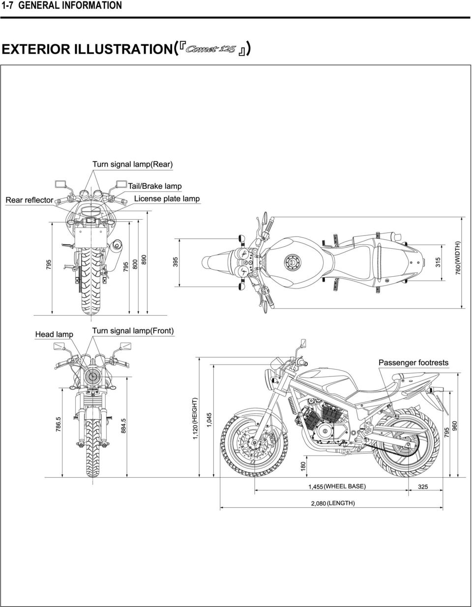
14 GENERAL INFORMATION 1-8 SPECIFICATIONS DIMENSIONS AND DRY MASS Overall length 2,080 mm (81.9 in) Overall width 760 mm (29.9 in) Overall height 1,120 mm (44.1 in) Wheelbase 1,455 mm (53.7 in) Ground clearance 180 mm (7.1 in) Unladen mass 170 kg (375 lbs) 167 kg (368 lbs) ENGINE Type Four-stroke, DOHC, air-cooled and oil-cooled Number of cylinder V-2 cylinder Bore 57.0 mm (2.24 in) 44.0 mm (1.73 in) Stroke 48.8 mm (1.92 in) 41.0 mm (1.61 in) Piston displacement 249 cm3 (15.2 in 3 ) cm3 (7.6 in 3 ) Carburetor BDS 26TYPE (DOUBLE) Starter system Electric starter Lubrication system Wet sump TRANSMISSION Clutch Wet multi-plate type Transmission 5-speed constant mesh Gearshift pattern 1-down, 4-up Final reduction Gear ratio, 1st nd rd th th Drive chain 520 HO 112 links 428 HO 136 links
 Carburetor BDS 26TYPE (DOUBLE) Starter system Electric starter Lubrication system Wet sump TRANSMISSION Clutch Wet multi-plate type Transmission 5-speed constant mesh Gearshift pattern")
15 1-9 GENERAL INFORMATION CHASSIS Front suspension Telescopic type Rear suspension Swingarm type Steering angle 33 (right & left) Caster 25.5 Trail 85 mm (3.35 in) 76 mm (2.29 in) Front brake Disk brake Rear brake Disk brake Front tire size 110/ H Rear tire size 150/ H Front fork stroke 120 mm (4.72 in) ELECTRICAL Ignition type CDI type Ignition timing Spark plug Battery Fuse Head lamp Turn signal lamp 13 B.T.D.C.at 2,000 rpm and 30 B.T.D.C.at 6,000 rpm CR8E 12V 12Ah 15 A HI : 60 W LO : 55 W 10 W Brake / Tail lamp 21 / 5 W Speedometer lamp 1.7 W 3 High beam indicator lamp 1.7 W Turn signal indicator lamp(right & left) 1.7 W 2 License plate lamp Neutral indicator lamp CAPACITIES 5 W 1.7 W HI : 35 W LO : 35 W Fuel tank 17.0 l Engine oil, oil change 1,450 ml with filter change 1,500 ml overhaul 1,800 ml 1,650 ml Front fork oil (One side) 400 ± 2.5 cc 262 cc NOTE The specifications are subject to change without notice.
 1.7 W 2 License plate lamp Neutral indicator lamp CAPACITIES 5 W 1.7 W HI : 35 W LO : 35 W Fuel tank 17.")
16 PERIODIC MAINTENANCE 2 CONTENTS PERIODIC MAINTENANCE SCHEDULE 2-1 PERIODIC MAINTENANCE CHART 2-1 LUBRICATION POINTS 2-2 MAINTENANCE PROCEDURES 2-3 VALVE CLEARANCE 2-3 SPARK PLUG 2-5 EXHAUST PIPE NUTS AND MUFFLER MOUNTING BOLTS 2-5 AIR CLEANER 2-6 CARBURETOR 2-7 FUEL HOSE 2-8 CLUTCH 2-8 ENGINE OIL 2-9 ENGINE OIL FILTER 2-10 DRIVE CHAIN 2-11 BRAKE SYSTEM 2-13 STEERING 2-17 FRONT FORK 2-17 REAR SUSPENSION TIRE 2-18 CHASSIS BOLTS AND NUTS 2-18 COMPRESSION PRESSURE 2-19 OIL PRESSURE 2-20

17 2-1 PERIODIC MAINTENANCE PERIODIC MAINTENANCE SCHEDULE The chart below lists the recommended intervals for all the required periodic service work necessary to keep the motorcycle operating at peak performance and economy. Item Air cleaner element Exhaust pipe nuts and muffler mounting bolts Valve clearance adjust Cylinder head nut Cylinder head & Cylinder Spark plug Fuel hose Engine oil filter Engine oil Throttle cable Idle speed Clutch CHASSIS Item Drive chain Brake Brake hose Brake fluid Tires Steering Front forks Rear suspension Chassis bolts and nuts Interval Interval Initial 1,000 km Every 4,000 km Every 8,000 km page Tighten Inspect Tighten Clean Inspect Replace Replace Inspect Inspect Inspect CAUTION More frequent servicing should be performed on motorcycles that are used under severe conditions. PERIODIC MAINTENANCE CHART ENGINE Clean every 3,000 km Replace every 12,000 km Tighten Inspect Tighten Remove carbon Clean Replace Inspect Replace every 4 years Replace Replace Inspect Inspect Inspect Initial 1,000 km Every 4,000 km Every 8,000 km page Clean and lubricate every 1,000km Inspect Inspect Inspect Inspect Inspect Replace every 4 years Inspect Replace every 2 years Inspect Inspect Tighten Inspect Inspect Inspect Inspect Tighten CAUTION Using poor quality replacement parts can cause your motorcycle to wear more quickly and shorten its useful life. Use only genuine Hyoung replacement parts or their equivalent

18 PERIODIC MAINTENANCE 2-2 LUBRICATION POINT Proper lubrication is important for smooth operation and long life of each working part of the motorcycle. Major lubrication points are indicated below. 1 Clutch lever holder 2 Drive chain 3 Side stand pivot and spring hook 4 Speedometer gear box 5 Front brake lever holder 6 Throttle cable 7 Rear brake pedal pivot O - Motor oil, G - Grease NOTE Before lubricating each part, clean off any rusty spots and wipe off any grease, oil, dirt or grime. Lubricate exposed parts which are subject to rust, with either motor oil or grease whenever the motorcycle has been operated under wet or rainy condition.

19 2-3 PERIODIC MAINTENANCE MAINTENANCE PROCEDURE This section describes the service procedure for each section of the periodic maintenance. VALVE CLEARANCE Inspect Interval Inspect Initial 1,000 km and Every 4,000 km. CAUTION The clearance specification is for COLD state. The valve clearance specification is different for intake and exhause valves. Valve clearance adjustment must be checked and adjusted, 1) at the time of periodic inspection, 2) when the valve mechanism is serviced, and 3) when the camshaft is disturbed by removing it for servicing. Remove the spark plug. (Refer to page 2-5) Remove the fuel tank. (Refer to page 4-1) Remove the cylinder head cover 1 and 2. Remove the magneto cover plug 3 and the timing inspection plug 4. Rotate the magneto rotor to set the front cylinder s piston at TDC (Top Dead Center) of the compression stroke. (Rotate the rotor until F line on the rotor is aligned with the center of hole on the crankcase.) 1 [FRONT CYLINDER] [REAR CYLINDER] To inspect the front cylinder s valve clearance, insert the thickness gauge to the clearance between the camshaft and the tappet. Valve clearance (when cold) IN mm (0.004~0.008 in) EX mm (0.008~0.012 in) Thickness gauge :
 at the time of periodic inspection, 2) when the valve mechanism is serviced, and 3) when the camshaft is disturbed by removing it for")
20 PERIODIC MAINTENANCE 2-4 If the clearance is out of specification, first remove the cam chain tensioner, camshaft housing, camshaft. To install the tappet shim at original position, record the shim NO. and clearance with A, B, C, D mark on the cylinder head as the illustration. Select the tappet that agree with tappet clearance (vertical line) and shim NO.(horizontal line) as refer to the tappet shim selection chart. (Refer to page ) Adjust valve timing, install the camshaft housing and the tensioner. After the crankshaft rotate about 10 times, measure the valve clearance. If the clearance be not agree, adjust the standard clearance as the same manner above. In case that valve adjustment which there is no the tappet shim selection chart, please follow instructions of example in the below. For example, the intake clearance is 0.4 and the shim is 170 (1.70 mm), select 195 (1.95 mm) of the shim which 170 (1.70 mm) of the shim add up the excess clearance 0.25 mm when adjust with the standard 0.15 as the intake standard clearance mm. CAUTION Valve clearance should be checked when the engine is cold. If you don t rotate the crankshaft about 10 times before measuring the valve clearance, there is no meaning of valve clearance. A C B D Rotate the magneto rotor to set the rear cylinder s piston at TDC(Top Dead Center) of the compression stroke. (Rotate the rotor 285 counter-clockwise from the F line, and until the R line on the rotor is aligned with the center of hole on the crankcase.) Inspect the rear cylinder s valve clearance with the same manner of the front cylinder.
 Adjust valve timing, install the camshaft housing and the tensioner. After the crankshaft rotate about 10 times, measure the valve clearance.")
21 2-5 PERIODIC MAINTENANCE SPARK PLUG Inspect Interval Clean Initial 1,000 km and Every 4,000 km, Replace Every 8,000 km. Disconnect the spark plug caps. Remove the spark plugs. TYPE Hot type Standard type Cold type SPARK PLUG SPECIFICATION CR7E CR8E CR9E Remove the carbon deposite with wire or pin and adjust the spark plug gap to mm, measuring with a thickness gauge. Spark plug gap Thickness gauge : mm (0.028~0.032 in) Check to see the worn or burnt condition of the electrodes. If it is extremly worn or burnt, replace the plug. And also replace the plug if it has a broken insulator, damaged thread, etc. Install the spark plug, and then tighten it to specified torque. Spark plug : 20~25 N m (2.0~2.5 kg m) 0.7 ~ 0.8mm (0.028 ~ in) EXHAUSE PIPE NUTS AND MUFFLER MOUNTING BOLTS Inspect Interval Tighten Initial 1,000 km and Every 4,000 km. Tighten the exhaust pipe nuts 1, and muffler mounting bolts 2 to the specified torque. Exhaust pipe nut : 18~28 N m (1.8~2.8 kg m) Muffler mounting bolt : 20~30 N m (2.0~3.0 kg m) [ Front Cylinder ] 1
22 PERIODIC MAINTENANCE AIR CLEANER Inspect Interval Clean Every 3,000 km, Replace Every 12,000 km. The air cleaner is located under the fuel tank. Remove the fuel tank. Remove the four screw 3. Pull up the air cleaner cover and the air cleaner element [ Rear Cylinder ] 3 4
23 2-7 PERIODIC MAINTENANCE Clean the air cleaner element for the following: When the air cleaner element clean with the air gun, necessarily blow at the inside by compressed air. Carefully examine the air cleaner element for tears during cleaning. Replace it with a new one if it is torn. Assemble the element completely or damage severely the engine. Be careful not to allow water to go inside the air cleaner element. CARBURETOR Inspect Interval Inspect Initial 1,000 km and Every 4,000 km. IDLE SPEED Connect an engine tachometer to the high tension cord. Start up the engine and set its speed at anywhere 1,450 and 1,550 rpm by turning throttle stop screw 1. Engine idle speed CAUTION Make this inspection when the engine is hot. 1,450 1,550 rpm Engine tachometer : CAUTION More frequent servicing may be performed on motorcycles that are used under severe conditions, also clean the air cleaner element when replacing the oil to prevent damage of the engine. 1 THROTTLE CABLE PLAY There should be mm play on the throttle cable. To adjust the throttle cable play. Tug on the throttle cable to check the amount of play. Loosen the lock nut 2 and turn the adjuster 3 in or out until the specified play is obtained. Secure the lock nuts while holding the adjuster in place. Throttle cable play mm (0.02~0.04 in) 2 3
24 PERIODIC MAINTENANCE 2-8 FUEL HOSE Inspect Interval Inspect Initial 1,000 km and Every 4,000 km, Replace every 4 years. Remove the front and rear seat. (Refer to page 6-1) Inspect the fuel hoses for damage and fuel leakage. If any defects are found, the fuel hoses must be replaced. CLUTCH Inspect Interval Inspect Initial 1,000 km and Every 4,000 km. Clutch play should be 4 mm as measured at the clutch lever holder before the clutch begins to disengage. If the play in the clutch is incorrect, adjust it in the following way : Loosen the lock nut 1 and screw the adjuster 2 on the clutch lever holder all the way in. Loosen clutch cable adjuster lock nut 3. Turn the clutch cable adjuster 4 in or out to acquire the specified play. Tighten lock nut while holding the adjuster in position. The clutch cable should be lubricated with a light weight oil whenever it is adjusted. Clutch cable play 4 mm (0.16 in) [ ] [ ]
25 2-9 PERIODIC MAINTENANCE GEARSHIFT LEVER HEIGHT ADJUSTMENT Loosen the lock nut 1. With the link rod 2 turned, adjust the gearshift lever height. ENGINE OIL Inspect Interval Replace Initial 1,000 km and Every 4,000 km. Oil change Filter change Overhaul engine Engine oil type Necessary amount of engine oil 1,450 ml 1,500 ml 1,800 ml SAE 10W/30 or 10W/40 API Over SG Oil should be changed while the engine is warm. Oil filter replacement at the above intervals, should be together with the engine oil change. Keep the motorcycle upright. Place an oil pan below the engine, and drain the oil by removing the filler cap 3 and drain plug 4. Tighten the drain plug 4 to the specified torque, and pour fresh oil through the oil filler. Use an API classification of Over SG oil with SAE 10W/30 or 10W/40 viscosity. Oil drain plug : 18~20 N m (1.8~2.0 kg m) 1,450 ml 1,500 ml 1,650 ml 1 2 Start up the engine and allow it to run for several minutes at idling speed. Turn off the engine and wait about three minutes, then check the oil level through the inspection window. If the level is below mark F, add oil to F level. If the level is above mark F, drain oil to F level.
26 PERIODIC MAINTENANCE 2-10 CAUTION Never operate the motorcycle if the engine oil level is below the Lower line mark(l) in the inspection window. Never fill the engine oil above the Upper line mark(f). Engine oil level being most suitable about 1mm under the Upper line mark(f) of the engine oil lens. In case of the engine oil pouring in excessively, the engine output being made insufficient. Be careful not to pouring in the engine oil excessively. CAUTION Necessarily, confirm and clean the oil strainer 1 when replace the engine oil (specially, when first replacement). CAUTION More frequent servicing may be performed on motorcycles that are used under severe conditions. ENGINE OIL FILTER Inspect Interval Replace Initial 1,000 km and Every 4,000 km. Drain the engine oil as described in the engine oil replacement procedure. Remove the oil filter cap 2. Remove the oil filter. Install the new O-ring Install the new oil filter. Install the new O-ring 4 and spring 5 to the oil filter cap. Install the oil filter cap. CAUTION Before installing the oil filter cap, apply engine oil lightly to the new O-ring
27 2-11 PERIODIC MAINTENANCE OIL FILTER INSTALLATION CAUTION When install the oil filter, necessarily, HYOSUNG character and 16510H05240 part s NO. install toward the outside, otherwise can damage the engine. WARNING Engine oil and exhaust pipes can be hot enough to burn you. Wait until the oil drain plug and exhaust pipes are cool enough to touch with bare hands before draining oil. Add new engine oil and check the oil level as described in the engine oil replacement procedure. DRIVE CHAIN Inspect Interval CAUTION Use HYOSUNG MOTORCYCLE GENUINE OIL FIL- TER only, since the other make s genuine filters and after-market parts may differ filtering performance and durability, which could cause engine damage or oil leaks. Hyosung motors genuine oil filter is also not usable for the motocycles. Clean and Lubricate Every 1,000 km. Visually check the drive chain for the possible defects listed below. (Support the motorcycle by the jack or block, turn the rear wheel slowly by hand with the transmission shifted to Neutral.) Loose pins Excessive wear Damaged rollers Improper chain adjustment Dry or rusted links Kinked or binding links If any defects are found, the drive chain must be replaced. INSERTION DIRECTION HYOSUNG 16510H05240 LUSTER MATERIAL OUTSIDE
28 PERIODIC MAINTENANCE 2-12 Loose the axle nut 1. NOTE When replacing the drive chain, replace the drive chain and sprocket as a set. Tense the drive chain fully by turning both chain adjusters 2, 3. Count out 21 pins (20 pitches) on the chain and measure the distance between the two points. If the distance exceeds the service limit, the chain must be replaced. Drive chain 20pitch length Service limit mm (12.58 in) mm (10.10 in) 3 Loosen or tighten both chain adjusters, until the chain has mm of slack in the middle between the engine and rear sprockets. The marks, on both chain adjusters must be at the same position on the scale to ensure that the front and rear wheels are correctly aligned. Drive chain slack mm (0.79 ~ 1.18 in)
29 2-13 PERIODIC MAINTENANCE Place the motorcycle on jack or block for accurate adjustment. After adjusting the drive chain, tighten the axle nut to the specified torque. Tighten both chain adjusters, securely. Rear axle nut : 90~140 N m (9.0~14.0 kg m) Recheck the drive chain slack after tightening the axle nut. Wash the drive chain with kerosine. If the drive chain tends to rust quickly, the intervals must be shortened. After washing and drying the chain, oil it with a engine oil or chain lubricating oil. CAUTION The drive chain for this motorcycle is made of the special material. The chain should be replaced with a 520HO for and 428SO for. Use of another chain may lead to premature chain failure. 20~30mm (0.79~1.18 in) BRAKE SYSTEM Inspect Interval [ BRAKE ] Inspect Initial 1,000 km and Every 4,000 km. [ BRAKE HOSE & BRAKE FLUID ] Inspect Initial 1,000 km and Every 4,000 km. Replace the brake hoses Every 4 years, Replace the brake fluid Every 2 years.
30 PERIODIC MAINTENANCE 2-14 BRAKE FLUID LEVEL CHECK Keep the motorcycle upright and place the handlebars straight. Check the brake fluid level by observing the lower limit line (LOWER) on the front brake fluid reservoir. When the level is below the lower limit line (LOWER), replenish with brake fluid that meets the following specification. Specification and Classification : DOT 3 or DOT 4 CAUTION The brake system of this motorcycle is filled with a glycol-based brake fluid. Do not use or mix different types of fluid such as silicone-based or petroleum-based. Do not use any brake fluid taken from old, used or unsealed containers. Never re-use brake fluid left over from the last servicing or stored for a long period. CAUTION Brake fluid, if it leaks, will interfere with safe running and immediately discolor painted surfaces. Check the brake hoses and hose joints for cracks and oil leakage before riding. BRAKE PAD WEAR The extend of brake pad wear can be checked by observing the grooved limit on the pad. When the wear exceeds the grooved limit, replace the pads with new ones. CAUTION Replace the brake pad as a set, otherwise braking performance will be adversely affected. FRONT AND REAR BRAKE PAD REPLACEMENT Remove the brake caliper. Remove the brake pads. To reassmble, reverse the above sequence. Front brake caliper mounting bolt : 18~28 N m (1.8~2.8 kg m) Rear brake caliper mounting bolt : 18~28 N m (1.8~2.8 kg m) LOWER LIMIT LINE [ Front Brake ] [ Rear Brake ] [ Front Brake ]
31 2-15 PERIODIC MAINTENANCE FRONT AND REAR BRAKE FLUID REPLACEMENT Place the motorcycle on a level surface and keep the handlebars straight. Remove the master cylinder reservoir cap and diaphragm. Suck up the old brake fluid as much as possible. Fill the reservoir with new brake fluid. Specification and Classification : DOT 3 or DOT 4 Connect a clear hose 1 to the air bleeder valve and insert the other end of the hose into a receptacle. Loosen the air bleeder valve and pump the brake lever until the old brake fluid is completely out of the brake system. [ Rear Brake ] 1 Close the air bleeder valve and disconnect the clear hose. Fill the reservoir with new brake fluid to the upper line. Replace the rear brake s fluid with the same manner of the front brake. Front brake caliper air bleeder valve :6~9 N m (0.6~0.9 kg m) Rear brake caliper air bleeder valve :6~9 N m (0.6~0.9 kg m)
32 PERIODIC MAINTENANCE 2-16 AIR BLEEDING OF THE BRAKE FLUID CIRCUIT Air trapped in the brake fluid circuit acts like a cushion to absorb a large proportion of the pressure developed by the master cylinder and thus interferes with the full braking performance of the brake caliper. The presence of air is indicated by sponginess of the brake lever and also by lack of braking force. Considering the danger to which such trapped air exposes the machine and rider, it is essential that, after remounting the brake and restoring the brake system to the normal condition, the brake fluid circuit be purged of air in the following manner : Fill the master cylider reservoir to top of the inspection window. Replace the reservoir cap to prevent dirt from entering it. Attach a hose to the air bleeder valve, and insert the free end of the hose into a receptacle. Bleed air from the brake system. Squeeze and release the brake lever several times in rapid succession and sqeeze the lever fully without releasing it. Loosen the bleeder valve by turning it a quarter of a turn so that the brake fluid runs into the receptacle, this will remove the tension of the brake lever causing it to touch the handlebar grip. Then, close the air bleeder valve, pump and squeeze the brake lever, and open the valve. Repeat this process until the fluid flowing into the receptacle no longer contains air bubbles. NOTE While bleeding the brake system, replenish the brake fluid in the reservoir as necessary. Make sure that there is always some fluid visible in the reservoir. Close the air bleeder valve, and disconnect the hose. Fill the reservoir with brake fluid to the upper line. Bleed the rear brake s air with the same manner of front brake. Front brake caliper air bleeder valve : 6~9 N m (0.6~0.9 kg m) Rear brake caliper air bleeder valve : 6~9 N m (0.6~0.9 kg m) CAUTION Handle brake fluid with care : the fluid reacts chemically with paint, plastics, rubber materials, etc.
33 2-17 PERIODIC MAINTENANCE FRONT BRAKE LAMP SWITCH The front brake lamp switch is located beneath the front brake lever. Loosen the switch fitting screws and adjust the timing by moving the switch body forward or backward. REAR BRAKE LAMP SWITCH Adjust the rear brake lamp switch so that the brake lamp will come on just before pressure is felt when the brake pedal is depressed. STEERING Inspect Interval Inspect Initial 1,000 km and Every 4,000 km. Steering should be adjusted properly for smooth turning of handlebars and safe running. Overtight steering prevents smooth turning of the handlebars and too loose steering will cause poor stability. Check that there is no play in the steering stem while grasping the lower fork tubes by supporting the machine so that the front wheel is off the ground, with the wheel straight ahead, and pull forward. If play is found, perform steering bearing adjustment as described in page 6-29 of this manual. FRONT FORK Inspect Interval Inspect Every 4,000 km. Inspect the front forks for oil leakage, scoring or scratches on the outer surface of the inner tubes. Replace any defective parts, if necessary. REAR SUSPENSION Inspect Interval Inspect Every 4,000 km. Inspect the rear shock absorber for oil leakage and mounting rubbers including engine mounting for wear and damage. Replace any defective parts, if necessary.(refer to page 6-36)
34 PERIODIC MAINTENANCE 2-18 TIRE Inspect Interval Inspect Initial 1,000 km and Every 4,000 km. TIRE TREAD CONDITION Operating the motorcycle with excessively worn tires will decrease riding stability and can lead to loss of control. Inspect shortage of tire thread s depth by the tire wear indicator. Replace the front and rear tires at once when appear the tire wear indicator. TIRE PRESSURE If the tire pressure is too high or too low, steering will be adversely affected and tire wear increased. Therefore, maintain the correct tire pressure for good roadability or shorter tire life will result. Cold inflation tire pressure is as follows. COLD INFLATION TIRE PRESSURE Front Rear CHASSIS BOLTS AND NUTS Inspect Interval SOLD RIDING DUAL RIDING KPa kgf/cm 2 psi KPa kgf/cm 2 psi Tighten Initial 1,000 km and Every 4,000 km. Check that all chassis bolts and nuts are tightened to their specified torque.(refer to page 7-12) Tire wear indicator mark CAUTION Tire wear indicator The standard tire on / is 110/ H for front and 150/ H for rear. The use of tires other than those specified may cause instability. It is highly recommended to use a HYOSUNG Genuine Tire.
35 2-19 PERIODIC MAINTENANCE COMPRESSION PRESSURE The compression of a cylinder is a good indicator of its internal condition. The decision to overhaul the cylinder is often based on the results of a compression test. Periodic maintenance records kept at your dealership should include compression reading for each maintenance service. Compression pressure Standard 14~16 kg/cm 2 (at 500 rpm) Service limit 12 kg/cm 2 (at 500 rpm) Low compression pressure can indicate any of the following conditions : Excessively worn cylinder wall Worn-down piston or piston rings Piston rings stuck in grooves Poor seating of valves Ruptured or otherwise defective cylinder head gasket COMPRESSION TEST PROCEDURE NOTE Before testing the engine for compression pressure, make sure that the cylinder head bolts are tightened to the specified torque values and valves are properly adjusted. Have the engine warmed up by idling before testing. Be sure that the battery used is in fullycharged condition. Remove the parts concerned and test the compression pressure in the following manner. Loosen the oil cooler mounting bolts from the frame. Remove all the spark plug. Fit the compression gauge in one of the plug holes, while taking care that the connection is tight. Keep the throttle grip in full-open position. Crank the engine a few seconds with the starter, and record the maximum gauge reading as the compression of that cylinder. Compression gauge : Standard Service limit Compression pressure 11~13 kg/cm 2 (at 500 rpm) 10 kg/cm 2 (at 500 rpm)
36 PERIODIC MAINTENANCE 2-20 OIL PRESSURE Check the oil pressure periodically. This will give a good indication of the condition of the moving parts. Oil pressure If the oil pressure is lower or higher than the specification, the following causes may be considered. LOW OIL PRESSURE Oil leakage from the oil passage Damaged O-ring Defective oil pump Combination of above items HIGH OIL PRESSURE Engine oil viscosity is too high Clogged oil passage Combination of the above items Standard 2.0 ± 0.5 kg/cm2 (at 65 3,000 rpm) OIL PRESSURE TEST PROCEDURE Check the oil pressure in the following manner. Remove the oil check plug and install the adapter of oil pressure gauge at the removed position. Connect an engine tachometer. Warm up the engine as follows : Summer : 10 min. at 2,000 rpm. Winter : 20 min. at 2,000 rpm. After warming up, increase the engine speed to 3,000 rpm. (with the engine tachometer), and read the oil pressure gauge. Oil pressure gauge : Engine tachometer : Oil pressure Standard 0.9 ~1.1 kg/cm2 (at 65 3,000 rpm)
37
38 ENGINE CONTENTS ENGINE REMOVAL AND REINSTALLATION 3-1 ENGINE REMOVAL 3-1 ENGINE REINSTALLATION 3-5 ENGINE DISASSEMBLY 3-7 STARTER MOTER 3-7 CYLINDER HEAD COVER 3-8 PISTON 3-12 MAGNETO COVER 3-13 MAGNETO ROTOR 3-13 CLUTCH COVER 3-14 CLUTCH 3-15 PRIMARY DRIVE GEAR 3-16 OIL PUMP 3-16 GEARSHIFT SHAFT 3-17 ENGINE COMPONENT INSPECTION AND SERVICE 3-19 ENGINE REASSEMBLY CAUTION Mark an identification of assembly location on each removed part so that each will be restored to the original position during reassembly. Wash clean and dry the removed parts before inspecting and measuring. Oil the rotating or sliding parts before assembly. Make sure to use the correct type of lubricant where specified. Check that each rotating or sliding part moves or operates smoothly after assembly. Make sure to follow the bolt tightening order where specified. If the correct length of the bolt is confused when tightening the crankcase or cover, insert all the bolts and check that the tightening margin is equal in each bolt.
39 3-1 ENGINE ENGINE REMOVAL AND REINSTALLATION ENGINE REMOVAL NOTE If the engine is dirtied, wash the machine with a suitable cleaner before removing the engine. Remove the front seat.(refer to page 6-1) Remove the fuel tank.(refer to page 4-1) Drain the engine oil.(refer to page 2-9) Disconnect the battery lead wire 1. CAUTION First, disconnect the lead wire. AIR CLEANER With the two screw loosened, remove the air cleaner case. Loosen the clamp screw. 1 CARBURETOR Remove the carburetor after removed the intake pipes. (Refer to page 4-5) Disconnect the vacuum hoses 2. ( ) 2
40 ENGINE 3-2 CLUTCH CABLE Disconnect the clutch cable end out of clutch lever. Disconnect the clutch cable end out of clutch release arm. EXHAUST PIPE AND MUFFLER With the exhaust pipe bolts and muffler mounting bolts removed, remove the exhaust pipes and mufflers. [ Front Cylinder ] [ Rear Cylinder ]
41 3-3 ENGINE ELECTRIC PARTS With take out the spark plug caps, remove the spark plug. Remove the starter motor lead wire. Remove the engine ground lead wire 1. [ Front Cylinder ] [ Rear Cylinder ] 1 Disconnect the magneto coupler 2. 2
42 ENGINE 3-4 ENGINE SPROCKET Remove the engine sprocket cover. Remove the breather hose. Loosen the bolt and remove the link rod. Flatten the lock washer. Remove the engine sprocket nut 1 and washer. NOTE When loosening the engine sprocket nut, depress the brake pedal. 1 Remove the engine sprocket. NOTE If it is difficult to remove the engine sprocket, loosen the rear axle nut, chain adjusters 2 3 to provide additional chain slack.(refer to page 2-11) 2 3
43 3-5 ENGINE Remove the oil cooler. Support the engine using an engine jack. Remove the engine mounting nuts and bolts. Remove the engine from the frame. CAUTION Remove the carburetor when removing or installing the engine necessarily. When removing the carburetor, loosen the intake pipe mounting bolts at the same time. ENGINE REINSTALLATION Reinstall the engine in the reverse order of engine removal. Install the engine mounting bolts and nuts. Tighten the engine mounting bolts and nuts to the specified torque. Engine mounting bolt : N m ( kg m)
44 ENGINE 3-6 ENGINE SPOCKET Loosen the rear axle nut and chain adjusters, left and right. Install the engine sprocket. Tighten the engine sprocket nut 1 to the specified torque. Engine sprocket nut : 80~100 N m (8.0~10.0 kg m) NOTE When tightening the engine sprocket nut, depress the rear brake pedal. Bend the lock washer securely. Install the gearshift arm and adjust the gearshift lever height.(refer to page 2-9) Connect each electric part and its couplers.(refer to page 7-23~30) Install the exhaust pipes and mufflers. Install the carburetor and air cleaner. 1 After remounting the engine, the following adjustments are necessary. Engine idling speed Refer to page 2-7 Throttle cable play Refer to page 2-7 Clutch cable play Refer to page 2-8 Drive chain Refer to page 2-11 Gearshift lever height Refer to page 2-9 Engine oil level Refer to page 2-9
45 3-7 ENGINE ENGINE DISASSEMBLY STARTER MOTOR Remove the starter motor. Remove the gear position switch. Remove the contacts 1 and springs Remove the three union bolts.
46 ENGINE 3-8 CYLINDER HEAD COVER Remove the cylinder head cover. To set the piston at TDC(Top Dead Center). CAUTION Align the index mark on the magneto rotor with the index mark on the magneto cover as turn the crankshaft counter-clockwise. To set piston at TDC(Top Dead Center) of the compression stroke as align the F mark for front cylinder and the R mark for rear cylinder. Remove the cam chain tensioner. [ Front Cylinder ] [ Rear Cylinder ]
47 3-9 ENGINE With the three bolts removed, remove the cam chain guide NO.2. Remove the camshaft housing. Remove the camshaft (IN. EX.). Remove the C-ring.
48 ENGINE 3-10 Loosen the two cylinder head base cover nuts. Loosen the three cylinder head base nuts. Loosen the four cylinder head stud bolts. Remove the chain guide NO.1 and cylinder head.
49 3-11 ENGINE Remove the tappet and the shim. CAUTION Draw out the tappet and shim with the strong magnet not to be scratched. CAUTION The tappet and shim should be lined so that each will be restored to the original position during reassembly. Compress the valve spring by using the special tool. Valve spring compressor : Valve spring compressor attachment : 09916H35C00 ( ) Valve spring compressor attachment : 09916H5100 ( ) Take out the valve cotter from the valve stem. Remove the valve spring retainer. Pull out valve from the other side.
50 ENGINE 3-12 Remove the two cylinder base nuts and cylinder. cylinder. CAUTION If tapping with the plastic hammer is necessary, pay attention to break the fins. Rear Cylinder Front Cylinder Piston pin puller : NOTE Make an identification on each piston head so that confirmed the Remove the rear cylinder head and cylinder with the same manner of the front cylinder head and cylinder removal. PISTION Place a clean rag over the cylinder base to prevent piston pin circlips from dropping into crankcase. Remove the piston pin circlips with long-nose pliers. Remove the piston pin by using the special tool.
51 3-13 ENGINE MAGNETO COVER Remove the magneto cover. Remove in the order of spacer 1, shaft 2, starter idle gear 3. MAGNETO ROTOR With the magneto rotor held immovable using the special tool, loosen the rotor nut. Conrod holder : Remove the magneto rotor by using the special tool. Rotor remover( ) : Rotor remover ( ) : Rotor remove sliding shaft :
52 ENGINE 3-14 Remove the key 1. Remove the starter driven gear 2. Remove the cam chain tensioner 3 and cam chain 4. CLUTCH COVER Remove the clutch release arm Remove the clutch cover bolts. Remove the clutch cover.
53 3-15 ENGINE CLUTCH With the primary drive gear held immovable, remove the clutch spring mounting bolts diagonally. Remove the disk pressure 1. Remove the clutch drive and driven plates. Flatten the lock washer With the clutch sleeve hub held immovable using special tool, remove the clutch sleeve hub nut. Clutch sleeve hub holder :
54 ENGINE 3-16 Remove the clutch sleeve hub 1 and primary driven gear assembly 2. PRIMARY DRIVE GEAR With the magneto rotor held immovable using special tool, remove the primary drive gear nut. Conrod holder : CAUTION This bolt has left-hand thread. If turning it counter-clockwise( ), it may cause damage. Pay attention at the primary drive gear with two washer. Remove the key and cam chain 3. Remove the cam chain tensioner OIL PUMP Remove the circlip 5 and oil pump driven gear. 5
55 3-17 ENGINE Remove the pin 1. With the three screws loosened, remove the oil pump 2. GEARSHIFT SHAFT Draw out the gearshift shaft 3. With the cam guide screws loosened, draw out the guide and lifter. Remove the cam driven gear. CAUTION Pay attention to not lost the gearshift pawl, pin, spring with the cam driven gear removal With the neutral cam stopper plug loosened, remove the washer, spring, stopper.
56 ENGINE 3-18 Remove the crankcase securing bolts. Separate the crankcase into 2 parts, right and left, with a special tool. Crankcase separator : CAUTION When separating the crankcase, necessarily, remove it after installed the special tool (Crankcase separator) on the side of clutch. In case separate oppositely, the gearshift cam stopper will be damaged in the side of magneto. NOTE Fit the crankcase separater, so that the tool arms parallel the side of the crankcase. Remove the gearshift fork shaft 1 and gearshift fork 2. Remove the gearshift cam 3. Remove the driveshaft assembly 4, countershaft assembly 5. Remove the oil pump idle gearshaft 6. Remove the crankshaft by using the special tool. Crankcase separator :
57 3-19 ENGINE ENGINE COMPONENT INSPEC- TION AND SERVICE Cylinder head distortion Valve head thickness CAUTION Be sure to identify each removed part as to its location, and lay the parts out in groups designated as Front cylinder, Rear cylinder, Exhaust, Intake, so that each will be restored to the original location during assembly. CYLINDER HEAD DISTORTION Decarbonate in combustion chamber. Check the gasketed surface of the cylinder head for distortion with a straightedage and thickness gauge, taking a clearance reading at several places as indicated. If the largest reading at any position of the straightedge exceeds the limit, replace the cylinder head. Service limit 0.05 mm (0.002 in) Thickness gauge : VALVE FACE WEAR Visually inspect each valve face for wear. Replace any valve with an abnormally worn face. The thickness of the valve face decreases as the face wears. Measure the valve head. If it is out of specification, replace the valve with a new one. Service limit 0.5 mm (0.02 in) Vernier calipers : VALVE STEM RUNOUT Check the valve stem for abnormal wear or bend. Place the valve on V-blocks and measure runout. If the service limit is exceeded or abnormal condition exists, replace the valve. (B.T.D.C) Intake open (T.D.C) (A.T.D.C) Exhaust close Valve stem runout Service limit 0.05 mm (0.002 in) Dial gauge : Magnetic stand : V-block : (A.B.D.C) Intake close (B.B.D.C) Exhaust open (B.D.C) Valve timing diagram
58 ENGINE 3-20 CAMSHAFT The camshaft should be checked for runout and also for wear of cams and journals if the engine has been noted to produce abnormal noise or vibration or a lack of output power. Any of these abnormality could be caused by a worn camshaft. CAMSHAFT WEAR Worn-down cams are often the cause of mistimed valve operation resulting in reduced output power. The limit of cam wear is specified for both intake and exhaust cams in terms of cam height, which is to be measured with a micrometer. Replace camshafts if found it worn down to the limit. Cam height Intake cam Exhaust cam Valve clearance Service limit mm (1.345 in) mm (1.343 in) Micrometer(25~50 mm) : Tappet & shim wear When measuring the valve clearance, the clearance should be within the standard range. Intake valve Exhaust valve Standard(When cold) 0.1~0.2 mm (0.004~0.008 in) 0.2~0.3 mm (0.008~0.012 in) (T.D.C) (B.T.D.C) Intake open (A.T.D.C) Exhaust close (B.B.D.C) Exhaust open (A.B.D.C) Intake close (B.D.C) Valve timing diagram Inspect the tappet for wear and scratch. If modification or scratch is present, replace the tappet. The shim has various size. Replace the thin shim to valve clearance is narrow, or the thick shim to valve clearance is wide as that shim thickness was installed with standard at present. (Refer to page ) SHIM KIND There are 41 kinds of shim which thickness is increased by each mm from 1.20 mm to 2.20 mm.
59 3-21 ENGINE VALVE HEAD RADIAL RUNOUT Place a dial gauge as shown and measure valve head radial runout. If the service limit is exceeded, replace the valve. Valve head radial runout Valve guide-valve stem clearance Valve stem diameter 4.475~4.490 mm Service limit 0.03 mm ( in) Dial gauge : Magnetic stand : V-block : VALVE GUIDE-VALVE STEM CLEAR- ANCE Measure the clearance in the valve guide-valve stem, by rigging up the dial gauge as shown. If the clearance is measured exceeds the limit specified below, then determine whether the valve or the guide should be replaced to reduce the clearance to within the standard range: IN. EX. IN. EX. Dial gauge : Magnetic stand : Standard 0.010~0.037 mm (0.0004~ in) 0.030~0.057 mm (0.0012~ in) VALVE STEM DIAMETER Measure the valve stem outside diameter. If the diameter measured exceeds the standard, replace the valve. Standard (0.1762~ in) (0.1565~ in) 4.455~4.470 mm 3.975~3.990 mm 3.955~3.970 mm (0.1754~ in) (0.1557~ in) Micrometer(0~25 mm) : VALVE SPRING The force of the coil spring keeps the valve seat tight. A weakened spring results in reduced engine power output and often accounts for the chattering noise coming from the valve mechanism. Check the valve springs for proper strength by measur ing their free length and also by the force required to compress them. If the spring length is less than the service limit or if the force required to compress the spring does not fall within the specified range, replace both the inner and outer springs as a set.
60 ENGINE 3-22 Valve spring free length(in. & EX.) Valve spring tension (IN. & EX.) Cylinder distortion mm (1.488 in) Service limit Venier calipers : ~13.9 kgf (26.7~30.6 lbs) Standard mm (1.482 in) 30.0 kgf (66.1 lbs) at length 33.7 mm (1.33 in) at length mm (1.10 in) CYLINDER DISTORTION Check the gasketed surface of the cylinder for distortion with a straightedge and thickness gauge, taking a clearance reading at several places as indicated. If the largest reading at any position of the straightedge exceeds the limit, replace the cylinder. Cylinder bore Standard ~ mm (2.2441~ in) Service limit 0.05 mm (0.002 in) Thickness gauge : CYLINDER BORE Measure the cylinder bore diameter at six place. If any one of the measurements exceeds the limit, overhaul the cylinder and replace the piston with an oversize, or replace the cylinder. Service limit mm ( in) Cylinder bore Standard ~ mm (1.7323~ in) Service limit mm ( in) Cylinder gauge set : CAM CHAIN TENSION ADJUSTER Check that the push rod slides smoothly with the lock shaft handle 1 clockwise. If it does not slide smoothly, replace the cam chain tension adjuster with a new one. 1
61 3-23 ENGINE CAM CHAIN TENSIONER Check the contacting surface of the cam chain tensioner. If it is worn or damaged, replace it with a new one. CAM CHAIN AND CAM CHAIN GUIDE Check the cam chain for wear, damage and kinked or binding links. If any defects are found, replace it with a new one. Check the cam chain guide for wear and damage. If it is found to be damaged, replace it with a new one. PISTON DIAMETER INSPECTION Measure the outside diameter of piston in the direction perpendicular to the piston pin axis at the height from the skirt as shown in the illustration using a micrometer. If the measurement is found less than the service limit, replace the piston. Piston diameter Piston oversize Piston-to-cylinder clearance Piston-to-cylinder clearance Standard 0.05~0.06 mm (0.0020~ in) Standard 0.03~0.04 mm (0.0012~ in) Service limit mm ( in) mm ( in) 0.5, 1.0 mm (0.02, 0.04 in) Micrometer(50~75 mm) : Micrometer(25~50 mm) : PISTON-TO-CYLINDER CLEARANCE To determine the piston-to-cylinder clearance, calculate the difference between the cylinder bore and outside diameter of the piston. Service limit mm ( in) Service limit 0.1 mm ( in) (0.6 in)
HYOSUNG MOTORS & MACHINERY INC. SERVICE MANUAL SERVICE MANUAL 99000HP8910
 HYOSUNG MOTORS & MACHINERY INC. SERVICE MANUAL SERVICE MANUAL 99000HP890 FOREWORD GROUP INDEX This manual contains an introductory description on HYOSUNG and procedures for its inspection/service and overhaul
13. REAR WHEEL/BRAKE/SUSPENSION
 13. REAR WHEEL/BRAKE/SUSPENSION 13 3.5~4.5kg-m 8.0~10.0kg-m 0.8~1.2kg-m 3.0~4.0kg-m 2.4~3.0kg-m 3.5~4.5kg-m 6.0~8.0kg-m 13-0 13. REAR WHEEL/BRAKE/SUSPENSION 13 REAR WHEEL/BRAKE/SUSPENSION SERVICE INFORMATION...
1/29/2008 DR70. Baja Motorsports Inc. P.O. Box 61150 Phoenix, AZ 85082 Toll Free: 888-863-2252 PART NUMBERS PRICES ARE SUBJECT TO CHANGE 1 of 43
 DR70 Toll Free: 888-863-2252 PART NUMBERS PRICES ARE SUBJECT TO CHANGE 1 of 43 CYLINDER & CYLINDER HEAD 1 DR70-001 883099044472 CYLINDER 1 1 2 DR70-002 883099044489 GASKET, CYLINDER 1 1 3 DR70-003 883099044496
Unit: mm(in) Item Standard value Service limit Axle shaft run out - 0.2(0.008)
 Item Standard value Service limit Axle shaft run out - 0.2(0.008)") Rear Wheel/Brake/Suspension 13. Rear Wheel/Brake/Suspension Service Information 13-1 Troubleshooting 13-2 Rear Wheel 13-3 Rear Cushion 13-4 Rear Swing Arm 13-7 Service Information General Safety If the
Rear Wheel/Brake/Suspension 13. Rear Wheel/Brake/Suspension Service Information 13-1 Troubleshooting 13-2 Rear Wheel 13-3 Rear Cushion 13-4 Rear Swing Arm 13-7 Service Information General Safety If the
1/29/2008 DR50. Baja Motorsports Inc. P.O. Box 61150 Phoenix, AZ 85082 Toll Free: 888-863-2252 PART NUMBERS PRICES ARE SUBJECT TO CHANGE 1 of 45
 DR50 Toll Free: 888-863-2252 PART NUMBERS PRICES ARE SUBJECT TO CHANGE 1 of 45 CYLINDER & CYLINDER HEAD Part UPC Number Description Baja Description 1 DR50-001 842645074424 CYLINDER 1 1 2 DR50-002 842645074431
1/29/2008 DR125 / DR150. Baja Motorsports Inc. P.O. Box 61150 Phoenix, AZ 85082 Toll Free: 888-863-2252 PARTS AND PRICES ARE SUBJECT TO CHANGE 1 of 55
 DR125 / DR150 Toll Free: 888-863-2252 PARTS AND PRICES ARE SUBJECT TO CHANGE 1 of 55 CYLINDER HEAD ASSY. 1 125-001 883099006937 CYLINDER HEAD COVER 1 1 2 125-002 883099006944 BOLT M6X28 2 3 3 125-003 883099006951
DR50 Hensim Dirt Runner 49cc Dirt Bike (VIN PREFIX LLCH or LUAH)
") Page 1 of 21 Product Information Baja Web > Product Information > Parts Lists > DIRTBIKE > DR50 Hensim Dirt Runner 49cc Dirt Bike (VIN PREFIX LLCH or LUAH) DR50 Hensim Dirt Runner 49cc Dirt Bike (VIN PREFIX
Page 1 of 21 Product Information Baja Web > Product Information > Parts Lists > DIRTBIKE > DR50 Hensim Dirt Runner 49cc Dirt Bike (VIN PREFIX LLCH or LUAH) DR50 Hensim Dirt Runner 49cc Dirt Bike (VIN PREFIX
DR90. Baja Motorsports Inc. P.O. Box 61150 Phoenix, AZ 85082 Toll Free: 888-863-2252 PART NUMBERS AND PRICES ARE SUBJECT TO CHANGE 1 of 51
 DR90 Toll Free: 888-863-2252 PART NUMBERS AND PRICES ARE SUBJECT TO CHANGE 1 of 51 CYLINDER & CYLINDER HEAD 1 DR90-001 842645048166 CYLINDER 1 1 2 DR90-002 842645048173 GASKET, CYLINDER 1 1 3 DR90-003
STEERING HANDLEBAR/FRONT WHEEL/ FRONT SHOCK ABSORBER
 14 14 STEERING HANDLEBAR/FRONT WHEEL/ SCHEMATIC DRAWING ------------------------------------------------- 14-1 SERVICE INFORMATION------------------------------------------------ 14-2 TROUBLESHOOTING-----------------------------------------------------
DR125 and DR150 Hensim Dirt Runner 125cc and 150cc Dirt Bike (VIN PREFIX LLCH or LUAH)
") Parts Lists - DR125 and DR150 Hensim Dirt Runner 125cc and 150cc Dirt Bike (VIN PR... Page 1 of 25 Product Information Baja Web > Product Information > Parts Lists > DIRTBIKE > DR125 and DR150 Hensim Dirt
Parts Lists - DR125 and DR150 Hensim Dirt Runner 125cc and 150cc Dirt Bike (VIN PR... Page 1 of 25 Product Information Baja Web > Product Information > Parts Lists > DIRTBIKE > DR125 and DR150 Hensim Dirt
DR90. Baja Motorsports Inc. P.O. Box 61150 Phoenix, AZ 85082 Toll Free: 888-863-2252 PART NUMBERS AND PRICES ARE SUBJECT TO CHANGE 1 of 51
 DR90 Toll Free: 888-863-2252 PART NUMBERS AND PRICES ARE SUBJECT TO CHANGE 1 of 51 CYLINDER & CYLINDER HEAD Part UPC Number Description Baja Description 1 DR90-001 842645048166 CYLINDER 1 1 2 DR90-002
BR150 Pmi Baja Reaction 150cc Go Kart (VIN PREFIX L4VM)
") Page 1 of 21 Product Information Baja Web > Product Information > Parts Lists > GOKART > BR150 Pmi Baja Reaction 150cc Go Kart (VIN PREFIX L4VM) BR150 Pmi Baja Reaction 150cc Go Kart (VIN PREFIX L4VM)
Page 1 of 21 Product Information Baja Web > Product Information > Parts Lists > GOKART > BR150 Pmi Baja Reaction 150cc Go Kart (VIN PREFIX L4VM) BR150 Pmi Baja Reaction 150cc Go Kart (VIN PREFIX L4VM)
3. INSPECTION/ADJUSTMENT
 3 3 INSPECTION/ADJUSTMENT SERVICE INFORMATION-------------------------------------------------- 3-1 MAINTENANCE SCHEDULE (XCITING 500) ------------------------- 3-3 MAINTENANCE SCHEDULE (XCITING 250) -------------------------
Volkswagen Jetta, Golf, GTI 1999, 2000 Brake System 47 Brakes - Hydraulic Components (Page GR-47)
") 47 Brakes - Hydraulic Components (Page GR-47) FS III front brake calipers, servicing Front brake caliper piston, removing and installing FN 3 front brake calipers, servicing Front caliper piston, removing
47 Brakes - Hydraulic Components (Page GR-47) FS III front brake calipers, servicing Front brake caliper piston, removing and installing FN 3 front brake calipers, servicing Front caliper piston, removing
INDEX INTRODUCTION. Reference No. 10-21L-01 R E V I S E D : 2 0 0 5 0 2
 10-21L-01 SRM-2305, SRM-2305SI 1 1 INTRODUCTION We are constantly working on technical improvement of our products. For this reason, technical data, equipment and design are subject to change without notice.
System Saver 318 Air Compressor for Mack E-Tech and ASET Engines
 Maintenance Manual 31 System Saver 318 Air Compressor for Mack E-Tech and ASET Engines Revised 08-05 NON-THROUGH DRIVE THROUGH DRIVE Service Notes About This Manual This manual provides service and repair
Volkswagen B3 Passat Manual Transmission 02A 34 Manual Transmission - Controls, Assembly (Page GR-34) 02A 5-speed. Gearshift cable/lever installing
 02A 5-speed. Gearshift cable/lever installing") 34 Manual Transmission - Controls, Assembly (Page GR-34) 02A 5-speed Gearshift cable/lever installing Gearshift housing repairing Gearshift lever repairing lever/relay lever, installing Gearshift mechanism
34 Manual Transmission - Controls, Assembly (Page GR-34) 02A 5-speed Gearshift cable/lever installing Gearshift housing repairing Gearshift lever repairing lever/relay lever, installing Gearshift mechanism
STEERING SYSTEM - POWER
 STEERING SYSTEM - POWER 1990 Nissan 240SX 1990 STEERING Nissan - Power Rack & Pinion Axxess, Maxima, Pulsar NX, Sentra, Stanza, 240SX, 300ZX DESCRIPTION The power steering system consists of a rack and
INSPECTION BEFORE RIDING
 INSPECTION BEFORE RIDING Check the following items before riding. ITEM Engine cum transmission oil Fuel Tyres Battery Speedometer Lighting Steering Throttle Clutch Brakes Wheels WHAT TO CHECK FOR Availability
TABLE OF CONTENTS. Section 1 - Assembling your new pit bike.
 Orion Pit Bike Sales Owners Manual (All information and content is the property of Orion Pit Bike Sales. Any attempt to copy or resell is a direct violation of our copyright. All violators will be prosecuted)
MAINTENANCE OF WHEELMOVE IRRIGATION SYSTEMS
 MAINTENANCE OF WHEELMOVE IRRIGATION SYSTEMS F. Richard Beard, Agricultural Equipment, Structures and Electricity Robert W. Hill, Biological & Irrigation Engineering Boyd Kitchen, Uintah County Extension
TECHNICAL BULLETIN. Meritor WABCO Cab Leveling Valves and Chassis Leveling Valves. How the Cab Leveling and Chassis Leveling Valves Work
 Revised 02-00 TECHNICAL BULLETIN Meritor WABCO Cab Leveling Valves and Chassis Leveling Valves This technical bulletin covers both cab and chassis leveling valves manufactured by Meritor WABCO. While the
CHROME FRONT BRAKE MASTER CYLINDER KIT
 -J075 REV. 009-0-0 CHROME FRONT BRAKE MASTER CYLINDER KIT GENERAL Kit Number 5-99D, 5-99D Models These Chrome Master Cylinder Kits are designed to replace the original equipment front brake master cylinder
2007 Hummer H3. 2007 BRAKES Disc Brakes - H3. Fastener Tightening Specifications Specification Application
 2007 BRAKES Disc Brakes - H3 SPECIFICATIONS FASTENER TIGHTENING SPECIFICATIONS Fastener Tightening Specifications Specification Application Metric English Backing Plate Bolts 135 N.m 100 lb ft Brake Hose
Raider Pro 250 (single-seat / double-seat): Service Manual EEC Version: 1.5 April.2005 FOREWORD
: Service Manual EEC Version: 1.5 April.2005 FOREWORD") FOREWORD This service manual has been specially prepared to provide all the necessary information for the proper maintenance and repair of the RAIDER PRO 250 (EEC-approved for on-road use). The Buggy fits
FOREWORD This service manual has been specially prepared to provide all the necessary information for the proper maintenance and repair of the RAIDER PRO 250 (EEC-approved for on-road use). The Buggy fits
DiscPlus DX195 and DX225 Air Disc Brakes
 Revised 11-04 Technical Bulletin Revised 1 Technical 11-04 Bulletin DiscPlus DX195 and DX225 Air Disc Brakes Inspection, Installation and Diagnostics Air Disc Brake Inspection Intervals and Procedures
Chapter 7 Hydraulic System Troubleshooting
 Chapter 7 Hydraulic System Troubleshooting General The following troubleshooting information is provided as a general guide to identify, locate and correct problems that may be experienced with the hydraulic
2003 ACCORD - Automatic Transmission Removal
 2003 ACCORD - Automatic Transmission Removal Special Tools Required Engine support hanger, A and Reds AAR-T-12566 Engine hanger balancer bar VSB02C000019 Front subframe adapter VSB02C000016 These special
12. REAR WHEEL/BRAKE/SUSPENSION
 12 12 12-0 SERVICE INFORMATION... 12-1 REAR BRAKE... 12-5 TROUBLESHOOTING... 12-2 REAR SHOCK ABSORBER... 12-8 REAR WHEEL... 12-3 REAR FORK... 12-9 SERVICE INFORMATION GENERAL INSTRUCTIONS When installing
Volkswagen Jetta, Golf, GTI 1999, 2000 Brake System 46 Brakes - Mechanical Components (Page GR-46)
") 46 Brakes - Mechanical Components (Page GR-46) Front brakes Brake pads, removing and installing Brake pads, removing and installing FN 3 brake caliper, servicing FS III brake caliper, servicing Rear wheel
46 Brakes - Mechanical Components (Page GR-46) Front brakes Brake pads, removing and installing Brake pads, removing and installing FN 3 brake caliper, servicing FS III brake caliper, servicing Rear wheel
Rebuild Instructions for 70001 and 70010 Transmission
 Rebuild Instructions for 70001 and 70010 Transmission Brinn, Incorporated 1615 Tech Drive Bay City, MI 48706 Telephone 989.686.8920 Fax 989.686.6520 www.brinninc.com Notice Read all instructions before
Cylinder head, removing and replacing
 15-1 Cylinder head, removing and replacing WARNING! Do not re-use any fasteners that are worn or deformed in normal use. Some fasteners are designed to be used only once, and are unreliable and may fail
ENGINE FUEL FUEL FILTER... FUEL HEATER... INJECTOR... SUPPLY PUMP... COMMON RAIL... FUEL PRESSURE LIMITTER...
 FUEL FILTER............................ FUEL HEATER.......................... INJECTOR.............................. SUPPLY PUMP.......................... COMMON RAIL.......................... FUEL PRESSURE
FZ6-ST FZ6-STC SUPPLEMENTARY SERVICE MANUAL LIT-11616-18-43 5VX-28197-11
 FZ6-ST FZ6-STC SUPPLEMENTARY SERVICE MANUAL LIT-66-8-43 5VX-2897- FOREWORD This Supplementary Service Manual has been prepared to introduce new service and data for the FZ6-ST/FZ6-STC. For complete service
Drive shaft, servicing
 Volkswagen Passat B6 - Drive shaft, servicing Стр. 1 из 41 40-7 Drive shaft, servicing Drive shafts, overview I - Assembly overview: Drive axle with CV joint VL100 40-7, Drive axle with CV joint VL100,
Quad Lander 250 SERVICE MANUAL
 FORWARD CONTENTS HOW TO USE THIS MANUAL SERIAL NUMBER Quad Lander 250 SERVICE MANUAL Homepage Contents FORWARD This service manual contains the technical data of each component inspection and repair for
ENGINE Dinli 904 D1033-011
 ENGINE Dinli 904 D1033-011 ENGINE Model Item Part no Description Specification Quantity 01 E140000-01 E14 ENGINE 450C.C. 1 FENDER SEAT D1033-021 FENDER SEAT Model Item Part no Description Specification
Trouble Shooting. Pump
 Trouble Shooting Pump Trouble Possible Cause Remedy Oil leaking in the area of water pump crankshaft Worn crankshaft seal, bad bearing, grooved shaft, or failure of retainer o-ring. Excessive play on crankshaft
Char-Lynn Hydraulic Motor. Repair Information. 10 000 Series. October, 1997
 Char-Lynn Hydraulic Motor October, 1997 Repair Information Geroler Motor Two Speed 001 27 Retainer inside bore of valve plate bearingless motors only 4 15 16 3 6 35 Parts Drawing 25 2 2 1 19 17 36 40 47
Rear wheel brakes, servicing. Стр. 1 из 45. Note:
 Volkswagen Touareg - Rear wheel brakes, servicing Стр. 1 из 45 46-2 Rear wheel brakes, servicing Rear brakes, FN 44 brake caliper, servicing Note: After replacing brake pads, depress brake pedal firmly
For exploded diagram and part number information, refer to the Spare Parts Catalog available on our website at www.rockshox.com.
 For exploded diagram and part number information, refer to the Spare Parts Catalog available on our website at www.rockshox.com. Information contained in this publication is subject to change at anytime
Adjustment Data MAZDA - 626-2.0 Comprex D - RF-CX
 Adjustment Data MAZDA - 626-2.0 Comprex D - RF-CX Engine (general) Engine code RF Capacity 1998 (cc) Idle speed 725 ± 25 Valve clearance Valve clearance Cold Inlet 0.25 (mm) Exhaust 0.35 (mm) Compression
TABLE OF CONTENTS. iii
 TABLE OF CONTENTS GENERAL INFORMATION 1 PERIODIC MAINTENANCE AND TUNE-UP PROCEDURES 5 ENGINE 9 LUBRICATION SYSTEM 24 FUEL SUPPLY SYSTEM 28 TRANSMISSION COMPONENTS 33 ELECTRICAL STARTING SYSTEM 36 BELT
C O N T E N T S 1 ABOUT THIS PARTS LIST... 2 ENGINE GROUP... 3 3 CONTENTS-FRAME GROUP
 C O N T E N T S 1 ABOUT THIS PARTS LIST... 2 2 CONTENTS-ENGINE ENGINE GROUP ENGINE GROUP... 3 3 CONTENTS-FRAME GROUP FRAME GROUP... 5 4 ENGINE PARTS LIST... 9 5 FRAME PARTS LIST...37 1 ABOUT THIS PARTS
Class 5 to 7 Truck and Bus Hydraulic Brake System
 Class 5 to 7 Truck and Bus Hydraulic Brake System Diagnostic Guide 1st Edition * 5+0 Important Service tes The information in this publication was current at the time of printing. The information presented
INSTRUCTIONS. FLHR/C/S (Road King) FRONT END LOWERING KIT 1WARNING -J03242 REV. 10-19-04. General. Removal (Left and Right Forks) Kit Number 54614-05
 FRONT END LOWERING KIT 1WARNING -J03242 REV. 10-19-04. General. Removal (Left and Right Forks) Kit Number 54614-05") INSTRUCTIONS -J04 REV. 0-9-04 General FLHR/C/S (Road King) FRONT END LOWERING KIT This kit is designed for installation on 00 and later FLHR/C/S Model Motorcycles. Road King models use the conventional
INSTRUCTIONS -J04 REV. 0-9-04 General FLHR/C/S (Road King) FRONT END LOWERING KIT This kit is designed for installation on 00 and later FLHR/C/S Model Motorcycles. Road King models use the conventional
Service Manual. 150cc Product 6150/7150/200 Series
 Service Manual 150cc Product 6150/7150/200 Series FOREWORD This service manual has been specially prepared to provide all the necessary information for the proper maintenance and repair of the 6150/7150
PREVENTION MAINTENANCE CHECKLIST FOR TRACTORS, TRUCKS, AND AUTOMOBILES
 PREVENTION MAINTENANCE CHECKLIST FOR TRACTORS, TRUCKS, AND AUTOMOBILES Farm Machinery Fact Sheet FM-21 By Dr. Von H. Jarrett, Extension Agricultural Engineer Systematic sequence for inspection GASOLINE
BUYERS GUIDE. IMPORTANT: Spoken promises are difficult to enforce. Ask the dealer to put all promises in writing. Keep this form.
 BUYERS GUIDE IMPORTANT: Spoken promises are difficult to enforce. Ask the dealer to put all promises in writing. Keep this form. VEHICLE MAKE MODEL YEAR VIN NUMBER DEALER STOCK NUMBER (Optional) WARRANTIES
Aprilia.no. RS 50 96-98 Eng.6M
 01 Carburettor - oil pump 02 Drive shaft 03 Head - piston 04 Primary gear shaft 05 Gearbox driven shaft 06 Selector 07 Clutch 08 Clutch cover 09 Right crankcase 10 Left crankcase 11 Ignition unit RS 50
Motorcycle 2012 Model: RM-Z250 Date: August 2011
 RM-Z250L2 Motorcycle 2012 Model: RM-Z250 Date: August 2011 New Features New graphics Key Features 1. 249cm3, 4-stroke, fuel-injected, DOHC engine, designed compact and lightweight, powers the RM-Z250's
Curriculum for Motorcycle Mechanic (6 Months)
") Curriculum for Motorcycle Mechanic (6 Months) Page 1 Contents Overall objective of the course: 3 Competencies gained after completion of the course:. 3 Job opportunities available immediately and in the
Curriculum for Motorcycle Mechanic (6 Months) Page 1 Contents Overall objective of the course: 3 Competencies gained after completion of the course:. 3 Job opportunities available immediately and in the
For exploded diagram and part number information, refer to the Spare Parts Catalog available on our website at www.rockshox.com.
 For exploded diagram and part number information, refer to the Spare Parts Catalog available on our website at www.rockshox.com. 2 0 0 5 D U K E A I R X C / S L / R A C E S E R V I C E G U I D E Information
SLP 1.85 Ratio Offset Rocker Arms with Valve Springs, LS3
 PART #50190 SLP 1.85 Ratio Offset Rocker Arms with Valve Springs, LS3 PACKING LIST Before installation, use this check list to make sure all necessary parts have been included. ITEM QTY CHECK PART NUMBER
Fuel Injection Pump, Rotary (005-014)
") Fuel Injection Pump, Rotary View Related Topic Page 1 of 30 Fuel Injection Pump, Rotary (005-014) Table of Contents Summary General Information Preparatory Steps Remove Front Gear Train Rear Gear Train
Fuel Injection Pump, Rotary View Related Topic Page 1 of 30 Fuel Injection Pump, Rotary (005-014) Table of Contents Summary General Information Preparatory Steps Remove Front Gear Train Rear Gear Train
Table of Contents. Overview 1. Pump Disassembly 2. Control Disassembly / Reassembly 7. Pump Reassembly 13. Adjustment Procedures DR Control 19
 Table of Contents Overview 1 Pump Disassembly 2 Control Disassembly / Reassembly 7 Pump Reassembly 13 Adjustment Procedures DR Control 19 Adjustment Procedures DRG Control 20 Adjustment Procedures DFR
LF-1 CYLINDER HEAD COVER
 PITBIKE AB, SWEDEN LIFAN 50cc SOHC parts catalogue Copyright PITBIKE AB, SWEDEN LF- CYLINDER HEAD COVER 5 6 7 8 9 0 5 /P5FMI 0/P5FMI /P50FMH /P5FMI-B /P5FMI /P5FMI 5/P50FMH GB/T9 /P5FMI 5/P5FMI 8/P50FMG
Webinar Series. Committee. Disc Brake Wheels Off Inspection and Reline. Presents
 1 APTA Bus Webinar Technical Series Maintenance Committee Webinar Series Presents Disc Brake Wheels Off Inspection and Reline January 21, 2015 2 Introduction Welcome to today s webinar in which we will
P7100 PUMP INSTALLATION INSTRUCTIONS Diesel Care & Performance Inc
 P7100 PUMP INSTALLATION INSTRUCTIONS Diesel Care & Performance Inc Installation Timing Pin Location CAUTION: Before installing the injection pump, be sure that number 1 cylinder is at the Top Dead Center
PARTS MANUAL EH12-2 ENGINE. Model. PUB-EP5713 Rev. 7/99
 PARTS MANUAL Model EH12-2 ENGINE PUB-EP5713 Rev. 7/99 940 Lively Blvd. Wood Dale, IL 60191 Phone: 630-350-8200 Fax: 630-350-8212 e-mail: sales@robinamerica.com www.robinamerica.com Copyright 1999 Robin
Cooling system components, removing and installing
 Engine BHW Cooling system components, removing and installing Page 1 / 24 19-1 Cooling system components, removing and installing Warning! When doing any repair work, especially in the engine compartment,
Turbocharger system components, servicing
 21-1 Turbocharger system components, servicing Engine codes: AAZ, 1Z, AHU Observe rules of cleanliness Page 21-10 Turbocharger hoses and lines, connecting Page 21-11 WARNING! Do not re-use any fasteners
PALLET JACK - 2.5 TON
 PALLET JACK - 2.5 TON 39939 SET UP AND OPERATING INSTRUCTIONS Visit our website at: http://www.harborfreight.com Read this material before using this product. Failure to do so can result in serious injury.
MODEL G300 BRAKE BLEEDER
 MODEL G300 BRAKE BLEEDER Installation, Operation & Repair Parts Information Branick Industries, Inc. 4245 Main Avenue P.O. Box 1937 Fargo, North Dakota 58103 REV060616 P/N: 81-0035G 1 THIS PAGE INTENTIONALLY
COVERED. WE VE GOT YOU H-D EXTENDED SERVICE PLAN GET TO KNOW THE HDFS FAMILY: ASK YOUR DEALER FOR MORE INFORMATION. www.hdfsi.com
 H-D EXTENDED SERVICE PLAN www.hdfsi.com WE VE GOT YOU COVERED. GET TO KNOW THE HDFS FAMILY: Harley-Davidson Insurance Harley-Davidson Extended Service Plan Harley-Davidson Debt Protection Plan Harley-Davidson
EM 58. 19. REMOVE NO. 2 MANIFOLD STAY (a) Remove the bolt, nut and stay.
 Remove the bolt, nut and stay.") 57 ROVAL 1. DISCHARGE FUEL SYST PRESSURE (See page FU-9) 2. DISCONNECT CABLE FROM NEGATIVE BATTERY TERMINAL CAUTION: Wait at least 90 seconds after disconnecting the cable from the negative (-) battery
57 ROVAL 1. DISCHARGE FUEL SYST PRESSURE (See page FU-9) 2. DISCONNECT CABLE FROM NEGATIVE BATTERY TERMINAL CAUTION: Wait at least 90 seconds after disconnecting the cable from the negative (-) battery
This is the civilian transfer case with the cooling loop only found in the driven gear half of the front case.
 INTRODUCTION The Transfer case used in the AMG Hummer is a New Venture Gear, model 242. This case has been in use for the H-1/Hummer since the early 1990 s. There have been modifications to the internal
DO NOT attempt to repair hub and wheel bearing assembly.
 Page 1 of 6 HUB & WHEEL BEARINGS (WITH PULSE VACUUM HUBLOCK) DO NOT attempt to repair hub and wheel bearing assembly. Removal DO NOT remove hub lock assembly by prying on hub lock legs. This can crack
MEASURING WHEEL ALIGNMENT
 MEASURING WHEEL ALIGNMENT 2003-04 WHEEL ALIGNMENT Specifications & Procedures - Hummer - H2 Steering and vibration complaints are not always the result of improper alignment. One possible cause is wheel
PRINCE 50 Parti di ricambio agg. al 30-11-09
 . 缸 头 罩 部 件 CYLINDER HEAD COVER(FOR EUROPE) 50000 COVER COMP HEAD 2 5000 GASKET HEAD COVER 3 50002 Aeration Head Cover 4 50372 AERATION CAP 5 50355 TUBE BREATHER 6 50356 TIE-IN 7 50358 AERATION TUBE ASSY
AUTOMOBILE MECHANIC STUDENT INTERNSHIP SKILLS LIST Provo School District
 AUTOMOBILE MECHANIC STUDENT INTERNSHIP SKILLS LIST Provo School District Repairs and overhauls automobiles, buses, trucks, and other automotive vehicles: Examines vehicle and discusses with customer or
11. COOLING SYSTEM 11-0 COOLING SYSTEM BET & WIN 50
 11 COOLING SYSTEM SERVICE INFORMATION------------------------------------------------ 11-1 TROUBLESHOOTING----------------------------------------------------- 11-1 RADIATOR ------------------------------------------------------------------
FJ2. 2 Ton Trolley Floor Jack Assembly & Operating Instructions
 FJ2 2 Ton Trolley Floor Jack Assembly & Operating Instructions READ ALL INSTRUCTIONS AND WARNINGS BEFORE USING THIS PRODUCT. This manual provides important information on proper operation & maintenance.
Service Manual Rol-Lift
 R 2000 Service Manual Rol-Lift Series: T and E Developed by Generic Parts Service This manual is intended for basic service and maintenance of the Rol-Lift pallet jack. The pallet jacks you are servicing
DYNA RIDER FOOTBOARD KIT
 -J0 REV. 0-0-0 DYNA RIDER FOOTBOARD KIT GENERAL Kit Number 000 Models For model fitment information, see the P&A Retail Catalog or the Parts and Accessories section of www.harley-davidson.com (English
Volkswagen Jetta, Golf, GTI 1999, 2000 2.8 Liter VR6 2V Engine Mechanical, Engine Code(s): AFP 17 Engine-Lubrication (Page GR-17)
: AFP 17 Engine-Lubrication (Page GR-17)") 17 Engine-Lubrication (Page GR-17) Lubrication system components, removing and installing Oil filter housing, disassembling and assembling Oil pan, removing and installing Oil pressure and oil pressure
17 Engine-Lubrication (Page GR-17) Lubrication system components, removing and installing Oil filter housing, disassembling and assembling Oil pan, removing and installing Oil pressure and oil pressure
SCREAMIN' EAGLE PRO TWIN CAM 110 (1800 CC) BOLT-ON CON- VERSION KIT
 BOLT-ON CON- VERSION KIT") -J0 REV. 0-0-0 SCREAMIN' EAGLE PRO TWIN CAM 0 (00 CC) BOLT-ON CON- VERSION KIT GENERAL Kit Number 000 Models For model fitment information, see the P&A Retail Catalog or the Parts and Accessories section
-J0 REV. 0-0-0 SCREAMIN' EAGLE PRO TWIN CAM 0 (00 CC) BOLT-ON CON- VERSION KIT GENERAL Kit Number 000 Models For model fitment information, see the P&A Retail Catalog or the Parts and Accessories section
Contents. Description Page Description Page
 Contents Description Page Description Page Auger Housing Assembly 1 Muffler 18 Handle and Control Assembly 3 Fuel Tank r Assembly 19 Engine and Drive Assembly 5 Clutch Retarder 20 Cylinder Head 7 Retarder
356 CHECKLIST ELECTRICAL: CHASSIS:
 356 CHECKLIST ELECTRICAL: Headlights hi/lo beam Taillights Running lights Turn signals Brake lights License light(s) Fog lights Reverse light Horn Dome lights Dash lights Temp guage Tank level guage Tachometer
FOR ANY QUESTIONS, PLEASE CALL US @ 727.347.9915 M-F 8:00a.m.-8:00p.m. EST. REAR BRAKES 1 AEROSPACE COMPONENTS 727.347.9915
 REAR BRAKES 1 AEROSPACE COMPONENTS 727.347.9915 REAR BRAKES Before getting started, remove all stock braking components. Pre-assembly of parts: Clean the bolts and the threads in the hat with acetone.
Volkswagen New Beetle 2.0 Liter 4-cyl General, Engine (Engine Code AEG) 15 Engine- Cylinder head, Valvetrain (Page GR-15)
 15 Engine- Cylinder head, Valvetrain (Page GR-15)") 15 Engine- Cylinder head, Valvetrain (Page GR-15) Cylinder head, removing and installing Compression, checking Valve train, servicing Camshaft oil seal, replacing Camshaft, removing and installing Hydraulic
15 Engine- Cylinder head, Valvetrain (Page GR-15) Cylinder head, removing and installing Compression, checking Valve train, servicing Camshaft oil seal, replacing Camshaft, removing and installing Hydraulic
INSIDE ENGINE COMPARTMENT TOYOTA AIR CONDITIONING ENGLISH EUROPE,GENERAL,AUSTRALIA
 INSIDE ENGINE COMPARTMENT TOYOTA AIR CONDITIONING ENGLISH EUROPE,GENERAL,AUSTRALIA INTRODUCTION IMPORTANT NOTICE This manual has been designed for technicians who are qualified and educated in the proper
1993 VOLKSWAGEN ENGINES 2.5L 5-Cylinder. EuroVan
 Article Text ARTICLE BEGINNING 1993 VOLKSWAGEN ENGINES 2.5L 5-Cylinder EuroVan * PLEASE READ THIS FIRST * NOTE: For engine repair procedures not covered in this article, see ENGINE OVERHAUL PROCEDURES
Slide the new steering column shaft through the steering column from the driver compartment.
 Slide the new steering column shaft through the steering column from the driver compartment. Push the column shaft through the steering column until the machined end is out past the column lower bushing.
Sample G1 ASE-type Certification Test. Sample ASE Maintenance and Light Repair (G1)-Type Certification Test
-Type Certification Test") Sample G1 ASE-type Certification Test Sample ASE Maintenance and Light Repair (G1)-Type Certification Test Content Area Questions In Test Percentage Of Test A. Engine Systems 9 16% B. Automatic 4 7% Transmissions
Sample G1 ASE-type Certification Test Sample ASE Maintenance and Light Repair (G1)-Type Certification Test Content Area Questions In Test Percentage Of Test A. Engine Systems 9 16% B. Automatic 4 7% Transmissions
POSEIDON 2-29, 2-25 & 2-22 POSEIDON 2-29, 2-25 & 2-22 XT
 POSEION 2-29, 2-25 & 2-22 POSEION 2-29, 2-25 & 2-22 XT Repair Manual Index A. Safety precautions 3 B. Technical data 4 C. Structure 5-6. Service / Repair 7-23 E. Tools 24 F. Function 25-26 G. Electric
ARTICLE BEGINNING APPLICATION IDENTIFICATION DESCRIPTION LUBRICATION & ADJUSTMENT TROUBLE SHOOTING. MANUAL TRANSMISSIONS Saab 5-Speed Transaxle
 Article Text ARTICLE BEGINNING MANUAL TRANSMISSIONS Saab 5-Speed Transaxle APPLICATION TRANSMISSION APPLICATION ÄÄÄÄÄÄÄÄÄÄÄÄÄÄÄÄÄÄÄÄÄÄÄÄÄÄÄÄÄÄÄÄÄÄÄÄÄÄÄÄÄÄÄÄÄÄÄÄÄÄÄÄÄÄÄÄÄÄÄÄ Vehicle Application Transmission
Oregon Fuel Injection
 Corporate Office: P.O. Box 21121, VE Pump Removal and Installation Cummins Lock Timed Applications Removal Clean the exterior of the injection pump and mounting surfaces. 1. Disconnect the fuel return
Motorcycle Service Manual
 KX450F Motorcycle Service Manual Quick Reference Guide This quick reference guide will assist you in locating a desired topic or procedure. Bend the pages back to match the black tab of the desired chapter
Pallet Jack. OWNER S MANUAL Model MH1230. Important Safety Instructions Assembly Instructions Parts and Hardware Identification
 OWNER S MANUAL Model MH1230 Important Safety Instructions Assembly Instructions Parts and Hardware Identification Pallet Jack CAUTION: Read, understand and follow ALL instructions before using this product
PUMP MAINTENANCE SCHEDULE AND CHECKLISTS
 PUMP MAINTENANCE SCHEDULE AND CHECKLISTS Providing a maintenance schedule defined specifically by run hours or yardage pumped serves only as a general guideline given the large amount of variables a unit
Front brakes (FN- 3), servicing
, servicing") j a t Front brakes (FN- 3), servicing 46-1 Front brakes, servicing Note: Install complete repair kit. After replacing brake pads and before moving vehicle, depress brake pedal several times firmly to properly
j a t Front brakes (FN- 3), servicing 46-1 Front brakes, servicing Note: Install complete repair kit. After replacing brake pads and before moving vehicle, depress brake pedal several times firmly to properly
Rotary Lift Trouble Shooting Guide
 Rotary Lift Trouble Shooting Guide INDEX I. Surface Lifts Page No. 1. Power Unit... 2 2. Two Post Lifts... 3 3. Four Post Lifts... 4 II. Inground Lifts 1. Semi and Full Hydraulic lifts... 5 2. Side by
Trouble Shooting Tech Tips Operation
 Steering Components TroubleShooting Tech Tips Table of Contents Basic Steering System Operation 2 Sector Shaft Adjustments 4 Drag Link Adjustment 5 Relief Valve/Unloading Valve Adjustment 6 Ross TAS Automatic
3620 W 11th Streetб Houston, TX 77008 Telephone: 713-635-6291 Email: sales@kellogg-american.com Website: www.kellogg-american.com
 Unpackaging & Handling Be sure to carefully inspect the unit before accepting the shipment. If any damage has occurred document it with the trucking company immediately. Contact your Kellogg Distributor
DR70-XR Xmoto 70cc Dirt Bike (VIN PREFIX L98B)
") Page 1 of 25 Product Information Baja Web > Product Information > Parts Lists > DIRTBIKE > DR70-XR Xmoto 70cc Dirt Bike (VIN PREFIX L98B) DR70-XR Xmoto 70cc Dirt Bike (VIN PREFIX L98B) Engine [Image] ENGINE
Page 1 of 25 Product Information Baja Web > Product Information > Parts Lists > DIRTBIKE > DR70-XR Xmoto 70cc Dirt Bike (VIN PREFIX L98B) DR70-XR Xmoto 70cc Dirt Bike (VIN PREFIX L98B) Engine [Image] ENGINE
SELF-STEERING AXLE TABLE OF CONTENTS
 SELF-STEERING AXLE TABLE OF CONTENTS Section 1 - Introduction Section 2 - Pre-Installation Check List Section 3 - Ride Height Adjustments Section 4 - Suspension Mount Section 5 - Axle Mount Section 6 -
BOWIE PUMPS OPERATION - MAINTENANCE
 BOWIE PUMPS OPERATION - MAINTENANCE PUMPING PRINCIPLE: The meshing owieeof the gears cause a slight depression, with the resulting enmeshing of the gears causing a vacuum drawing the fluid being pumped
2006 HEADSHOK Service Video #1
 LEFTY SPEED DLR DAMPING CARTRIDGE This document explains how to properly remove, disassemble, inspect, reassemble and reinstall the Lefty Speed DLR2 damping cartridge. It is a document to be used in conjunction
REMOVAL AND INSTALLATION
 303-01C-1 REMOVAL AND INSTALLATION Engine Body On Special Tool(s) Adapter For 303-D043 303-D043-02 or equivalent Special Tool(s) 303-01C-1 Turbocharger Lifting Bracket 303-1266 Wrench, Fan Clutch Nut 303-214