Operations & Maintenance Manual. Weatherford MP10 Mud Pump
|
|
|
- Vivien Riley
- 10 years ago
- Views:
Transcription
1 Operations & Maintenance Manual Weatherford MP10 Mud Pump

2 Model MP10 Triplex Mud Pump The Weatherford Model MP10 is a single acting triplex mud pump rated for 1000 HP in oilfield drilling applications. Compatibility with field proven design standards and high quality fabrication techniques assure performance and durability in the most demanding drilling conditions. The pump is supplied skid mounted with a comprehensive array of accessory equipment. Specifications Rated Power HP Maximum Speed RPM (at crankshaft) Minimum Speed...40 RPM (at crankshaft) Stroke Length...10 IN Gear Reduction Ratio :1 Rated Rod Load...84,100 LB Complete Pump Kit Weight.39,900 LB Pump & Skid Only Weight..35,500 LB Valve Pot...API-6 Maximum Fluid Temp F Mechanical Efficiency...90% Performance Ratings Plunger Size (Inch) Displacement (GAL/REV) Rated Pressure (PSI) Pump Capacity Jackshaft Speed 170 RPM 450 RPM 500 RPM 550 RPM 590 RPM , , , , , , , Horsepower [email protected] 2006 Weatherford. All Rights Reserved MP10RB
 Stroke Length...10 IN Gear Reduction Ratio...4.207:1 Rated Rod Load...84,100 LB Complete Pump Kit Weight.39,900 LB Pump & Skid Only Weight..35,500 LB Valve Pot.")
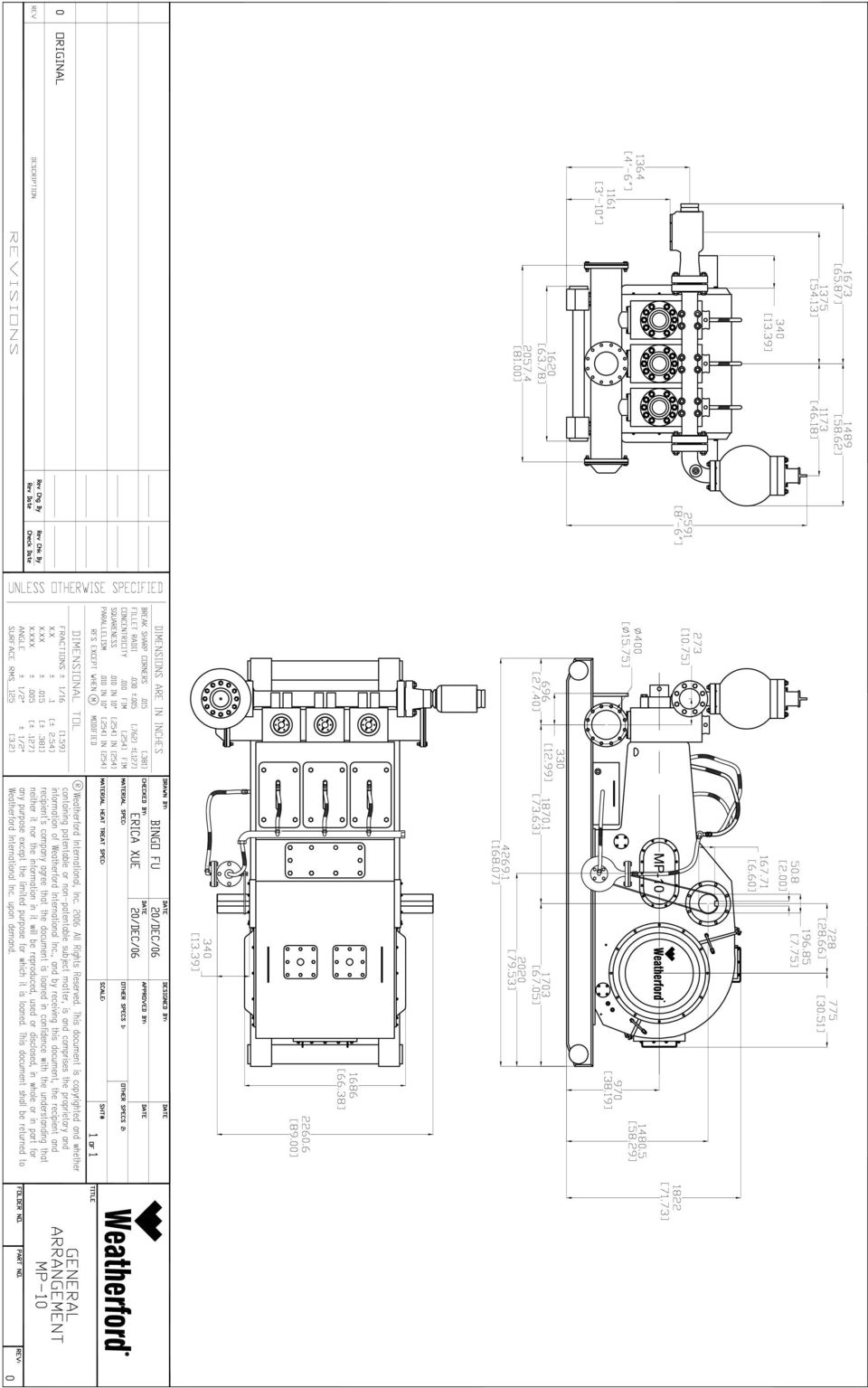
3 Model MP10 General Dimensions Suction: 12 Flanged Discharge: 5-1/8 API Flanged Note: 1. Capacities shown based on 100% volumetric efficiency. Actual capacities will be lower based on discharge pressures and fluid properties. 2. Drawings shown are typical and should not be used for fabrication purposes. Weatherford products and services are subject to Weatherford s standard terms and conditions. For more information concerning the full line of Weatherford products and services, please consult your authorized Weatherford representative. Unless noted otherwise, trademarks and services noted herein are the property of Weatherford. [email protected] 2006 Weatherford. All Rights Reserved MP10RB

4 PINION SHAFT ASSY FRAME ASSY CROSSHEAD ASSY FLUID END ASSY PULSATION DAMPENER ASSY DISCHARGE BLOCK ASSY RELIEF VALVE ASSY CRANKSHAFT ASSY HOSE SYSTEM ASSY MP1000 LUBRICATING SYSTEM ASSY

5
6

7
8
9
10

11

12

13

14
15

16 PARTS LIST Weatherford Mud Pump MP10 Revision Level A Item Part Number Frame Assy. Parts Torque Ft-Lb Qty Assembly, frame, MP Cover, window, inclined, MP Gasket, cover, window, inclined, MP Bolt 1/2"-13UNC-2BX1 3/ Cover, top, w/ breather seat, MP Gasket, cover, top, MP Bolt 1/2"-13UNC-2BX1 3/ Cap, breather, MP SCREW 5/8"-11UNCX7.28" NUT 5/8"-11UNC Pin, cylinder, 1/2 x 1.78, MP Pim, cotter, MP Signboard, rotation, MP Bolt 1/2"-13UNC-2BX1 3/4" Plate, window, back, MP Gasket, plate, window, back, MP Plug, Z, 1/2", NPT, MP Cartridge, scale, oil, MP Scale, oil, MP Gasket, plate, drain, MP SCREW 1/2"-13UNCX1 3/4" Plate, drain w/ relief, MP Plate, drain, MP Bolt 5/8"-11UNCX1 3/4" Cover, window, profile, MP Gasket, cover, window, profile, MP Gasket, flat, 14, MP Meter, pressure, 60x0-145psi, MP Chassis, frame, MP Bolt 1"-8NCX3" Nut 1"-8UNC-2B Washer, M Hood, canvas, MP10-1 Weatherford International 515 Post Oak Blvd Houston, Texas /29/2009, Page 1 of 10

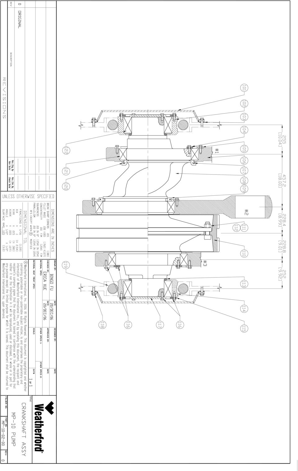
17 PARTS LIST Weatherford Mud Pump MP10 Revision Level A Item Part Number Crankshaft Assy. Parts Torque Ft-Lb Qty ASSEMBLY, CRANKSHAFT, MP10, WFT COVER, MAIN BEARING, MP10, WFT CARRIER, BEARING LEFT, MP10, WFT GASKET, MAIN BEARING COVER, MP10, WFT RETAINER, INNER RACE, OUTBOARD BRG, MP10, WFT RETAINER, OUTER RACE, ECC. BRG, MP10, WFT STRAP, ECCENTRIC, MP10, WFT RETAINER, CRANKSHAFT BRG. INNER, MP10, WFT CRANKSHAFT, MP10, WFT RETAINER, INNER RACE, CENTER BRG, MP10, WFT GEAR, ECCENTRIC RING, BIG, MP10, WFT CAPSCREW, 1 1/2-8UNC X 4 1/ NUT, LOCK, 11/2-8UNC SPACER, MAIN BRG, MP10, WFT CARRIER, BEARING, RIGHT, MP10, WFT RETAINER, OUTER RACE, MAIN BRG, MP10, WFT CAPSCREW, DRILLED HEAD, 5/8-11UNC X 1 1/ RETAINER, INNER RACE, MAIN BRG, MP10, WFT BOLT 5/8-11UNC X 1 3/ Bolt 2 1/2"-8UNCX15.2" Screw, allen 5/8"-11UNCX2 1/2" Bearing, 929/558.8QV, MP Bearing, HY, MP10-2 Weatherford International 515 Post Oak Blvd Houston, Texas /29/2009, Page 2 of 10

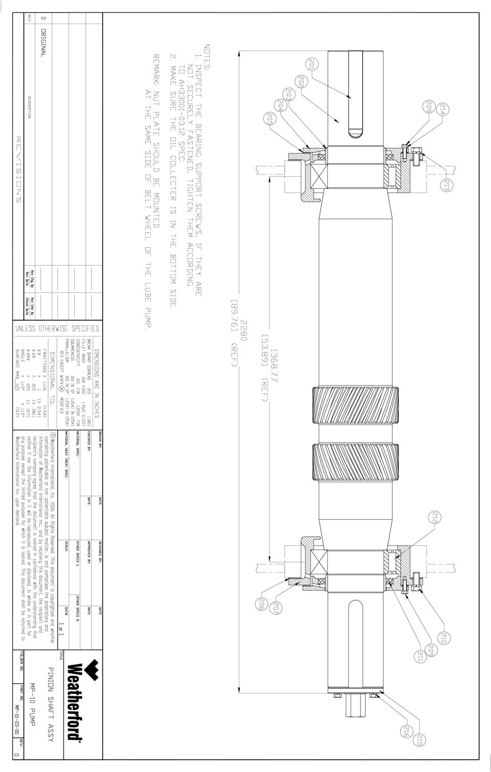
18 PARTS LIST Weatherford Mud Pump MP10 Revision Level A Item Part Number Pinion Shaft Assy. Parts Torque Ft-Lb Qty ASSEMBLY, PINION SHAFT, MP10, WFT KEY, 2IN X 2IN X 8IN SHAFT, PINION, MP10, WFT RING, OIL SEAL WEAR, MP10, WFT CARRIER, OIL SEAL, MP10, WFT GASKET, OIL SEAL CARRIER, MP10, WFT GASKET, OIL SEAL CARRIER, MP10, WFT CARRIER, PINION BEARING, MP10, WFT CAPSCREW, HEX HEAD, 1/2-13UNC X 1 3/ CAPSCREW, HEX HEAD, 7/8-9UNC X SEAL, OIL, 8.5 X 10.5 X BEARING, PINION SHAFT E32840H, MP10, WFT WASHER, LOCK, M WASHER, LOCK, M Jigger, manual, MP Bolt 5/8"-11UNCX2" - 3 Weatherford International 515 Post Oak Blvd Houston, Texas /29/2009, Page 3 of 10

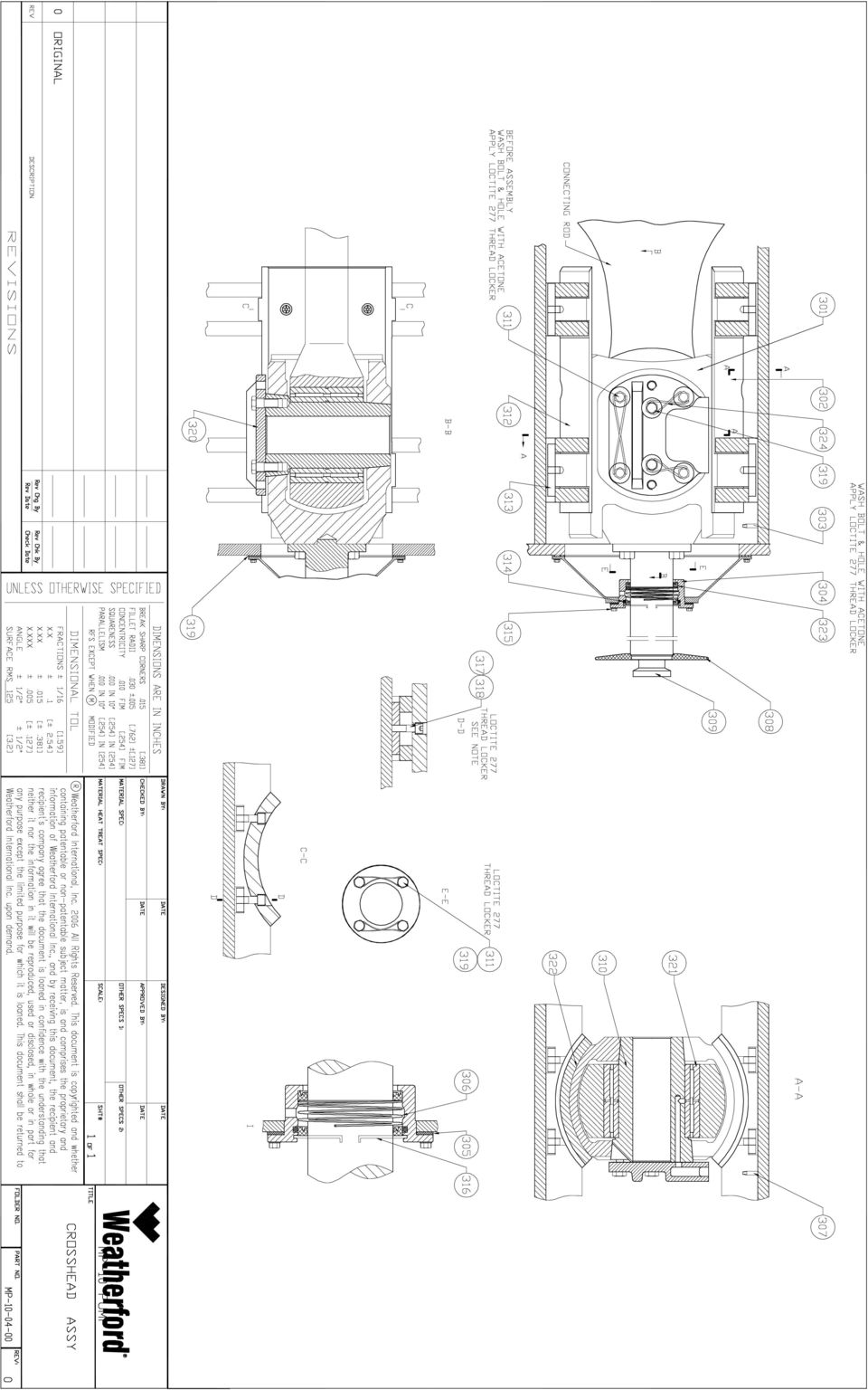
19 PARTS LIST Weatherford Mud Pump MP10 Revision Level A Item Part Number Cross Head Assy. Parts Torque Ft-Lb Qty ASSEMBLY, CROSSHEAD, MP10, WFT CROSSHEAD, MP10, WFT GUIDE, CROSSHEAD UPPER, MP10, WFT Plug, lube port crosshead MP BOX, DIAPHRAM STUFFING, MP10, WFT GASKET, DIAPHRAM STUFFING BOX, MP10, WFT SPRING, DIAPHRAM STUFFING BOX, MP10, WFT NIPPLE, PIPE, 3/8 X 2, MP10, WFT Plate, baffle, fluid, MP EXTENSION, CROSSHEAD, MP10, WFT PIN, CROSSHEAD, MP10, WFT CAPSCREW, HEX HEAD, DRILLED, 1-8UNC X 2 1/ GUIDE, CROSSHEAD LOWER, MP10, WFT PLATE, LOCKING, CROSSHEAD GUIDE, MP10, WFT BAFFLE, FLUID DISC, MP10, WFT, RUBBER Bolt 3/8"-16UNCX1 1/2' RETAINER, RING, SEAL DIAPHRAM STUFFING BOX, MP10, WFT CAPSCREW, SOCKET HEAD, 3/4-10UNC X 2 1/ LOCTITE THREADLOCKER N/A WIRE, ZINC PLATED CS, L=300mm - N/A RETAINER, CROSSHEAD PIN, MP10, WFT BEARING, CROSSHEAD H, MP10, WFT GASKET, DIAGHRAM PLATE, MP10, WFT - N/A SEAL, DOUBLE LIP, 4.5 X 5.5 X 0.5, MP10, WFT Screw, allen 1"-8UNCX2 1/2" - 12 Weatherford International 515 Post Oak Blvd Houston, Texas /10/2009, Page 1 of 1

20 PARTS LIST Weatherford Mud Pump MP10 Revision Level A Item Part Number Fluid End Assy. Parts Torque Ft-Lb Qty ASSEMBLY, MODULE, FLUID CYLINDER, MP MODULE, FLUID CYLINDER, MP10 WFT, 4135, NICKLE COATING RING, THREAD, MP10, WFT HEAD, CYLINDER, MP10, WFT SEAL, CLYLINER, MP10, WFT PLUG, CYLINDER HEAD, MP10, WFT CAGE, LINER, MP10, WFT ORING, 92.5 X 3.55, HNBR MANIFOLD, DISCHARGE, MP10, WFT SEAL, VALVE COVER, MP10, WFT STUD 1 1/2-8UNC X NUT, HEX, 1 1/2-8UNC - 2B COVER, VALVE, MP10, WFT GUIDE, VALVE, UPPER, MP10, WFT Cylinder, Hydraulic, MP RETAINER, UPPER VALVE GUIDE, MP10, WFT RETAINER SCREW 3/8"-16UNC X Washer, M SPRING, VALVE, MP10, WFT ASSEMBLY, VALVE, MP10, WFT NUT, LOCK, PISTON, MP10, WFT Piston, 5.00IN, MP8/ Piston, 5.50IN, MP 8/ Piston, 6.00IN, MP 8/ Seal, piston, MP ROD, PISTON, MP10, WFT Liner, 5.00, MP 8/ Liner, 5.50IN, MP 8/ Liner, 6.00IN, MP 8/ ASSEMBLY, HOSE, MP10, WFT CLAMP, PISTON ROD, MP10, WFT SPRING, VALVE GUIDE, MP10, WFT ORING, 185 X 7, HNBR CAPSCREW, HEX HEAD, 7/8-9UNC X 45MM MANIFOLD, SUCTION, MP10, WFT FLAT, WASHER M Bolt 7/8"-9UNCX3.15" NUT, HEX, 7/8-9UNC - 2B Gasket, 355 X 341 X δ2, MP FLANGE, BLIND SUCTION, MP10/13/16, WFT COVER, FLANGE, SUCTION MANIFOLD, MP10, WFT BAG, AIR, SUCTION MANIFOLD, MP Nut, 1 1/2"-8UNC-2B STUD 1 1/2-12UNF - 8UNC X Gasket, M39, MP NUT, HEX, 1 1/4-8UNC - 2B STUD 1 1/4-12UNF - 8UNC X NUT, HEX, 1 3/8-8UNC - 2B STUD 1 3/8-12UNF - 8UNC X Weatherford International 515 Post Oak Blvd Houston, Texas /29/2009, Page 5 of 10

21 PARTS LIST Weatherford Mud Pump MP10 Revision Level A Item Part Number Discharge Block Assy. Parts Torque Ft-Lb Qty Assembly, block discharge, MP Block, discharge, MP Filter, discharge, MP Connector, block, discharge, MP Flange, blind, discharge block, MP Flange, discharge, MP Connector, flange, MP Ring, seal, M95.25, MP Flange, welded, cinnector bend, MP Ring, seal, M161.93, MP Ring, seal, M161.94, MP Bolt, 1 1/2"-8UNC-12UNCX Nut, 1 1/2"-8UNC-2B Stud, 7/8"-9UNCX Nut, 7/8-9UNC-2B Bolt, 7/8"-9UNC-1 1/2" - 8 Weatherford International 515 Post Oak Blvd Houston, Texas /29/2009, Page 6 of 10
22 PARTS LIST Weatherford Mud Pump MP10 Revision Level A Item Part Number Lubrication Assy. Parts Torque Ft-Lb Qty Assembly, system, lubricating, MP Pump, lubricating, 2S, MP Sleeve, taper, lubricating, MP Gear, M9, lubricating, MP Strainer, lubricating, wo/ tube, MP Connector, 1/2"-3/4"-16UNC Connector, 3/8"-9/16-16UNC Connector, 1/2"-15/16-16UNC Elbow, connector, Z 1/4"X9/16-16UNC Elbow, connector, Z 3/8"X9/16-16UNC Nut, 15/16"-16UNC Nut, 3/4"-16UNC Nut, M8.2X9/16"-16UNC Tube, copper, M8-9200mm Tube, copper, M mm Tube, copper, M mm Tube, copper, M mm Weatherford International 515 Post Oak Blvd Houston, Texas /29/2009, Page 7 of 10
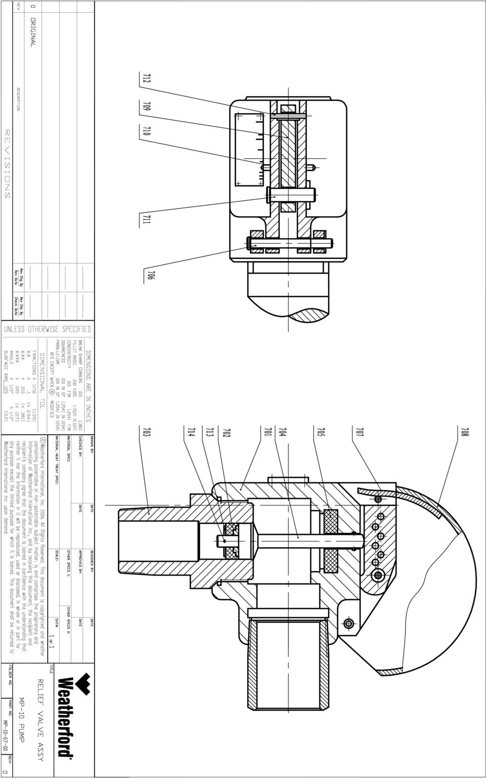
23 PARTS LIST Weatherford Mud Pump MP10 Revision Level A Item Part Number Relief Valve Assy. Parts Torque Ft-Lb Qty ASSEMBLY, VALVE, LEVER TYPE HIGH PRESSURE RELIEVE, MP10, WFT BLOCK, FLUID CYLINDER, RELIEF VALVE, MP10, WFT PISTON, RELIEF VALVE, MP10, WFT BODY, VALVE, MP10, WFT ROD, VALVE, MP10, WFT PLATE, DAMPING, RELIEF VALVE, MP10, WFT PIN, LONG, MP10, WFT LOCK WASHER, RELIEF VALVE, MP10 WFT CAGE, RELIEF VALVE, MP10, WFT CUTTER, RELIEF VALVE, MP10, WFT PIN, SAFETY, RELIEF VALVE, MP10, WFT PIN, SHORT, RELIEF VALVE, MP10, WFT PIN, RETAINING, RELIEF VALVE, MP10, WFT WASHER, FLAT, M PIN, GROOVED, MP10, WFT - 1 Weatherford International 515 Post Oak Blvd Houston, Texas /29/2009, Page 8 of 10
24 PARTS LIST Weatherford Mud Pump MP10 Revision Level A Item Part Number Hose System Assy. Parts Torque Ft-Lb Qty Assembly, system, hose, MP Assembly, tank, water, MP Pump, hose, MP Flange, pump, hose, MP Seat, pump, hose, MP Cover, pump, hose, MP Belt, pump, hose, 3048, MP Tube, main, hose, 3049, MP Hose 5/8" Hose 1" Sheave, hose, MP Connector, Z1"X1 1/2"-12UNC Connector, exteror, NPT, Z1"XZ1" MP Connector, inner, NPT, Z1", MP Connector, 3/8"X9/16"-16UNCX2" Elbow, connector, NPT, Z1"XZ1"X Bolt, 1/2"-13UNCX2 1/2" Nut, 1/2"-13UNC-2B Bullnose, Z1", MP10-3 Weatherford International 515 Post Oak Blvd Houston, Texas /29/2009, Page 9 of 10
25 PARTS LIST Weatherford Mud Pump MP10 Revision Level A Item Part Number Pulsation Dampner Assy. Parts Torque Ft-Lb Qty ASSEMBLY, DISCHARGE DAMPENER (KB-75), MP SERIES WFT Window, inspection, pulsation dampner, MP TEE, CHARGING, PULSATION DAMPENER, MP SERIES Botl, connection, pulsation dampner, MP NUT, COMPRESSION, PULSATION DAMPENER, MP SERIES PLUG, INLET, PULSATION DAMPENER, MP SERIES VALVE, CHECK, MP SERIES WFT GAUGE, PSI, BACK MOUNT LIQUID FILLED COVER, TOP, DAMPENER, MP SERIES WFT BLADDER, DAMPENER, MP SERIES WFT PLATE, FILTER, PULSATION DAMPENER, MP SERIES HOUSING, PULSATION DAMPENER, MP SERIES Screw, allen, 5/8"-11UNCX2" Stud, 1 1/2"-8UNC-12UNCX Nut, 1 1/2"-8UNC-2B - 12 Weatherford International 515 Post Oak Blvd Houston, Texas /29/2009, Page 10 of 10
26 Operation & Maintenance Manual Weatherford MP8 & MP10 Mud Pump
27 Page 2, Document OMM810, Revision A
28 TABLE OF CONTENTS PREFACE...4 SAFETY PRECAUTIONS...5 SPECIFICATIONS...6 INSTALLATION...7 DRIVE SYSTEMS...7 DRIVE SYSTEMS...8 SUCTION SYSTEM REQUIREMENTS...9 RELIEF VALVE...10 LINER WASH SYSTEM...11 POWER END OIL...12 LUBRICATION SYSTEM...14 TORQUE PRELOAD VALUES...15 PREVENTATIVE MAINTENANCE SCHEDULE...16 MAINTENANCE AND INSPECTION SCHEDULE...17 INITIAL STARTUP...18 NORMAL MAINTENANCE...19 VALVE REPLACEMENT...20 PISTON AND LINER REPLACEMENT...23 EXTENSION RODS & OIL SEALS...26 MAJOR SERVICE...29 CROSSHEAD CLEARANCE & ALIGNMENT...30 MAIN GEAR REPLACEMENT...32 BEARINGS...33 MAIN BEARING CAP INSTALLATION...35 FLUID END MODULE REPLACEMENT...36 Page 3, Document OMM810, Revision A
29 PREFACE The information provided in this document has been provided to support and guide the personnel who operate, maintain, and monitor the performance of the mud pumping equipment on drilling rigs. Weatherford mud pumps are very durable machines, however proper operation and maintenance procedures are absolutely critical for safely and to insure the pumps provide the expected service life. This document is intended to for skilled operators and mechanics that have previous experience working with similar types of equipment. Basic pump and hydraulic experience, as well as heavy equipment mechanic experience, is required as a prerequisite. It is not written as a training guide for inexperienced operators or mechanics. Stop and request additional assistance if you feel you do not have sufficient skills, tools, or training to safely and effectively operate or maintain this equipment. Weatherford pumps are sold and supported through Weatherford company stores and our extensive network of authorized distributors. All Weatherford distributors have the ability to answer your questions and provide you the support you may need to maintain and service your pump. Weatherford reserves the right to change or update all information provided in this document, at any time, without notice. Page 4, Document OMM810, Revision A
30 SAFETY PRECAUTIONS 1. Do not perform any operation, maintenance, or lubrication of this equipment until you have read and understood the information provided to you in this manual. If you have any questions please contact Weatherford. 2. Never attempt a service procedure until you are certain all pressure has been removed from the pump and the drive is disengaged and all lock-out, tag-out procedures have been complied with. 3. Never operate the pump without a relief valve, rupture disk, or other type of overpressure safety device properly installed. 4. Never exceed the rated pressure or speed of the pump for any reason. 5. Never operate the pump without proper guards in place for all moving parts. 6. Use caution when solvents are used to clean or degrease equipment. Most solvents are highly flammable. Such solvents can also diffuse into the body through skin and eye contact and can cause health hazards -- use proper protective clothing as required by the Material Safety Data Sheet for each solvent. Weatherford cannot anticipate every possible circumstance that might involve a potential hazard; therefore the warnings listed in this publication are not inclusive. As the user, you must decide if a particular operating mode, repair technique, or tool is safe before performing or using. Contact Weatherford or our authorized distributor for the most complete and current information before starting any repair job. Contact Weatherford at any time if you are unsure about any procedure involving Weatherford equipment. Page 5, Document OMM810, Revision A
31 SPECIFICATIONS MP8 MP10 Maximum Rated Power (HP) 800 1,000 Maximum Rated Speed (RPM) Minimum Rated Speed (RPM) Pump Type Triplex Triplex Stroke Length (IN) 9 10 Internal Gear Reduction Ratio 4.185: :1 Gear Type Double Helical Double Helical Valve Pot Size API-6 API-6 Pump Weight (LB) 32,900 39,900 Nominal Oil Capacity (GAL) Oil Type & Viscosity 0 F-85 F Ambient AGMA No. 4 EP AGMA No. 4 EP 30 F-155 F Ambient AGMA No. 6 EP AGMA No. 6 EP Maximum Operating Pressure (PSI) 4 5,000 5, /2 4,275 5, ,575 4, /2 2,950 3, ,475 3, /2 2,100 2,500 Displacement (GAL/REV per Crankshaft Revolution) / / / Pressure limited by standard fluid end module. High pressure modules are available as an option for services at up to 7,500 PSI. Consult Weatherford for additional information. Page 6, Document OMM810, Revision A
32 INSTALLATION Weatherford mud pumps come mounted to a small I-Beam style oilfield skid. The skid is used to protect the pump during initial transportation to a location for unitization; however it may also be used as part of the larger structural skid for the complete mud pump package with power. In some cases, packagers my prefer to remove the standard Weatherford skid and mount the pump directly to a larger skid with power and inlet piping to reduce the overall size and weight of the equipment package. In any case, it is critical that the supporting foundation directly under the pump be level and strong enough to support the forces and vibrations generated by the pump during operation. Do not use bolts to force the pump frame to mate up with an uneven mounting surface. The standard skid is resistant to bending, but can be twisted relatively easily of the pump is not mounted properly, or the skid is not located on a level and solid foundation. Due to the wide variety of different unitization systems used by Weatherford distributors and end users, you should contact the company that integrated the pump to the skid with power for any questions about the suitability of the pump location. Page 7, Document OMM810, Revision A
33 DRIVE SYSTEMS The most common method of driving a Weatherford mud pump is through V-Belts or a chain drive. Since the introduction of Kevlar belt reinforcements, the vast majority of these pumps are now connected to engines or motors using V- belts. They require less maintenance and are typically more economical to install than a comparable chain drive. Direct drive arrangements, either through a drive shaft or coupling, are also possible but are rarely used in actual practice. V-Belt Drive Precautions: 1. Periodically check the condition of the sheave grooves for damage such as wear or cracks. The side walls of the belt grooves should be straight and show no signs of unusual wear or rounding. Operation with rusted or worn grooves will rapidly wear the V-belt. Never operate the pump with any signs of cracks or other structural damage in the sheave. 2. Before the belts are tensioned, the sheaves should be aligned. It is critical that the grooves are aligned on both sheaves, and that the faces of the sheaves are square. This insures the pump shaft and the driver shaft are parallel. If the sides of both sheaves are the same distance from the edge of the V-belt, the easiest way to check the alignment is to pull a string or wire across the centerline of the sheaves from one end to the other. Move one sheave in or out until the string contacts each sheave face on two locations. 3. V-belts should be tensioned by moving the sheaves apart with a suitable screw and plate system that is integral to the pump base. Due to the wide variety of different belt designs available today, consult with the supplier of the belt and sheaves for information regarding the proper belt tension, tightening procedure for the hub. Do not exceed the recommended belt tension under any circumstances, such as trying to compensate for worn sheaves or belts. 4. Once the belts have tensioned, perform a final check of the alignment and insure all mounted bolts are secure. Due to the wide variety of different methods to secure a sheave to the shaft, consult the supplier of the sheave for instructions on how to properly secure the sheave and hub to the shaft. Chain Drive Precautions Chain drive systems are not supplied directly from Weatherford. Chain drives require emersion in an oil bath to lubricate the chain. Consult your chain drive supplier for specific information on the care and maintenance of your chain drive. Page 8, Document OMM810, Revision A
34 SUCTION SYSTEM REQUIREMENTS Weatherford mud pumps should be coupled to a centrifugal charge pump to insure a good supply of fluid and pressure are maintained at the pump inlet at all times. Running the pump with insufficient suction pressure due to incorrectly sized charge pump or poor inlet piping design can cause the pump to run rough and also dramatically reduce the life of pistons, liners, valves, and power end components. It is possible to run the pumps off tank pressure only in certain situations, however it is not recommended. The optimal pressure at the pump inlet during operation is PSI, and the normal accepted range of pressure is PSI. These pressures should be measured at the pump inlet, while the pump is running. The centrifugal charge pump should be sized to provide at least 20% more flow the maximum required by the pump with the largest size plunger you expect to run in normal operation. It is suggested that a pressure gauge be installed in the suction piping just before the pump inlet. This gauge can be very useful to help diagnose potential suction system issues once the equipment is in operation. The charge pump may be driven using V-belts off of the mud pump input shaft, however this method makes it difficult to efficiently mount the pump and inlet system piping, and also may not provide sufficient RPM to the charge pump for proper operation when the mud pump is operating at lower speeds. The most common method is to use a booster pump powered by an AC electric motor. The control panel for the mud pump should be setup so that the mud pump cannot be started until the centrifugal charge pump is running and had developed at least 15 PSI. Weatherford mud pumps are supplied with an inlet manifold with 3 flanged connections. The pump can be operated with suction pipe connected to any one of these inlets. The inlet piping should be at least 12 in diameter, the same as the pump inlet, and should be as straight and free of bends, elbows, and restrictions as possible. A run of at least 5 of straight pipe directly before the inlet of the pump is ideal. Page 9, Document OMM810, Revision A
35 RELIEF VALVE Under no circumstances should the Weatherford mud pump be operated without a relief valve or rupture disc in place. A properly installed pressure relief device is absolutely critical prevent damage to the pump and to insure the safety of people working in the area. The relief valve must be mounted directly on the outlet of the pump discharge flange with no valves or other devices upstream of it that could restrict or block the flow to the valve. The relief valve should be set to open and relieve pressure at no more that 15% above the rated discharge pressure of the pump. Note that the rated discharge pressure of the pump is not the rated pressure of the fluid end modules; it is the rated pressure of the particular size piston currently installed in the pump. Both shear pin style and reset style relief valves are acceptable, but the set, or cracking, pressure of both should be checked regularly to insure they are fully functional and properly sized to the pistons currently in the pump. The relief valves should be sized to insure they can pass the full flow of the pump, with maximum size pistons installed, with only a small back pressure rise of less than 100 PSI when bypassing the full flow of the pump. The return line from the relief valve should be piped to go back to the mud tank, and not the inlet of the pump. The return line should be equal to the outlet size of the relief valve, and there should be no restrictions or valves in the line that could be accidentally closed and interfere with the relieving action of the relief valve. The relief valve should be mounted above the level of mud in the tank and the return line run gradually sloping down to the tank level with no dips or low spots where mud could collect, harden, and potentially block the return flow back to the tank. Most contractors have specific policies about the relief valve piping, and Weatherford suggests these policies by followed. If there are any concerns or questions, please contact Weatherford directly for more information. Page 10, Document OMM810, Revision A
36 LINER WASH SYSTEM Mud pump pistons require a constant supply of cool fluid on the back, or atmospheric side of the piston during operation for proper life. This fluid and associated delivery method are commonly referred to as the liner wash system. The fluid serves to lubricate the boundary between the piston and liner to reduce friction and also to carry away heat generated by the wiping action of the piston on the liner walls. To insure optimal service life of both the pistons and liners, it is absolutely critical that the liner wash system be properly installed and maintained. Approximately 10 gallons per minute of fluid per cylinder is required to insure properly lubricate and cool the pistons and liners, and even a few second disruption of this flow during operation can cause the pistons and liners to fail. The typical liner wash fluid is a mixture of water and RV style anti-freeze. The anti-freeze prevents freezing, and also provides additional lubricity to the fluid that improves durability. The Weatherford MP8 and MP10 pumps are supplied with a moving nozzle type liner wash system. Cooling fluid is pumped from a charge pump and flexible rubber hose through a specially designed extension rod clamp. A copper spray tube connects to the clamp and directs the flow of cooling fluid directly on the back side of the piston assembly where it is then deflected to the ID of the liner. This method insures the back of the piston and bore of the liner are constantly flooded with fluid at all times during operation. The system should be inspected daily to insure that: 1. The liner wash fluid is clean and free of contamination from the drilling mud. The drilling mud is abrasive and will adversely affect the durability of the pistons and liners. The water will pick up a bit of drilling mud that leaks past the pistons, so it s important to change it regularly. 2. An ample supply of fluid is flowing from each of the spray tubes. 3. The spray tubes are properly aligned and spraying directly on the back of the piston assemblies. Improperly aligned spray tubes will allow excessive liner wash fluid to splash onto the crosshead extension rods, which could contaminate the power end oil. 4. The hose that supplies fluid to the clamps is not cracked or kinked. 5. The spray fluid is cool and has not overheated. 6. Clean out the screens and settling chamber in the fluid reservoir. Page 11, Document OMM810, Revision A
37 POWER END OIL One of the most important aspects of pump operation and maintenance is to insure that the power end oil is maintained at the proper level, is clean and free of contamination, and is regularly changed as part of an ongoing maintenance program. It is also important to insure that the oil pressure lubrication pump is operating properly. Operating the pump with oil levels below recommended, with dirty or contaminated oil, or when the pressure lubrication pumps are not working properly can cause premature wear on the power end, including complete failure of the power end bearings and gears. Fixing this kind of damage is expensive and often required a full overhaul at a repair center. Weatherford warranty does not cover damage that results from operation with substandard lubrication. Weatherford receive a factory run test before shipment, however all oil is drained from the pumps after testing, so the pumps are shipped without any oil in the power end. Before operating the pump, remove the power end inspection cover and check for any water or debris that may have accumulated during shipment or storage. Clean and flush the power end if necessary before filling with new oil. The power end must be filled with oil before the pump can be operated. The MP8 and MP10 pumps require a nominal capacity of 100 gallons; however the actual oil level should be monitored and adjusted using the dipsticks. Weatherford supplies each pump with two dipsticks, conveniently located on either side of the pump at the rear of the power end. Use only new, high quality oil in the Weatherford pumps. The power end oil is critical maintaining the durability of the power end components, so this is one area where it is wise to spend whatever money is necessary to insure you are getting the best quality available. This is important: Operation of the pump for any period of time with the wrong type, poor quality, contaminated, or different viscosity oils will result in premature wear and potentially irreversible damage to the power end components. Use only non-corrosive, anti-foaming gear oil with extreme pressure (EP) additive. The actual oil viscosity required is dependent on the ambient temperatures expected in operation. Oil Type & Viscosity 0 F-85 F Ambient AGMA No. 4 EP AGMA No. 4 EP 30 F-155 F Ambient AGMA No. 6 EP AGMA No. 6 EP Page 12, Document OMM810, Revision A
38 Once each week, check the oil level in the pump using the oil dipsticks (10) located on either side of the power frame. The stationary level should be measured only when the pump is not in operation and has been allowed to sit for at least 10 minutes to allow the oil in the pump to fully drain back into the sump. The proper oil level is filled to the mark as shown below for both stationary and running positions. Page 13, Document OMM810, Revision A
39 LUBRICATION SYSTEM The power end of the Weatherford mud pump is lubricated by a combination of splash and pressurized oil directed to critical areas by copper tubing from a common oil distribution manifold mounted on the back of the power frame, and then also a smaller distribution manifold at the top of the crosshead chamber. The standard oil pressure system supplied is a small internally mounted gear pump driven off the main gear. Normal operating pressure varies based on pump speed, oil viscosity, and operating pressure, however it should be between PSI in most cases. Pumps with this system in place can be operated at crankshaft speeds as low as 40 RPM provided that the oil pressure reading is at least 5 PSI. A small relief valve is installed on the main oil distribution manifold. This valve is set to crack open at 40 PSI to relieve excess pressure. Oil pressure should be steady. It will be higher when first starting a pump and the oil is cold, but will drop as the oil temperature increases to normal operating levels. When performing major inspections of the pump, always check to make sure oil flows easily from all oil injection ports, and that the copper distribution lines are not damaged, bent, or the connections have worked loose. Also, regularly check the condition of the pump inlet strainer and clean as necessary. A plugged strainer will cause the oil pressure to drop. An external, motor driven lube system with filter is an option. The standard internal lube pump and distribution manifold is shown below. The normal backlash between the lube pump gear and the main gear should be when cool to allow room for the gear teeth to expand when the pump reaches operating temperature and not place excessive side loads on the lube pump shaft. Page 14, Document OMM810, Revision A
40 TORQUE PRELOAD VALUES Insuring that the critical fasteners are properly preloaded with torque prior to initial startup, during routine, semi-annual inspections, and during any maintenance procedures will help insure your Weatherford mud pump performs properly, with a minimum of downtime or maintenance required. Failure to use proper torque values can cause fasteners to come loose over time which could result in major damage, or may cause the studs to fail due to stress fatigue. It is very important to achieve the torque values listed. Insufficient torque as well as excessive torque can both cause failures. An impact wrench may be used to draw up bolts but cannot be relied on to provide a final torque preload. Always use a calibrated torque wrench to apply the final torque values to the nut or bolt. For easy and accurate identification, the proper torque values for all fasteners are provided on the Part List of the pump next to each respective item. Use these values when performing the maintenance procedures listed in the following sections. Page 15, Document OMM810, Revision A
41 PREVENTATIVE MAINTENANCE SCHEDULE Regular preventative inspection and maintenance is vital to the keeping the Weatherford pumps operating properly year after year. It will allow you to detect small problems early, when they can be easily fixed before they become major issues that involve downtime and expensive repairs. Each company should have their own program in place, but below is a minimal set of areas to check and inspect that should be a mandatory part of any preventative maintenance schedule: 1. Inspect the power end oil for signs of contamination. Flush and change if necessary. Before adding new oil, carefully flush away and contaminants form the power end, especially in the oil troughs below the crossheads and in the compartment on the tops of the crosshead guides. Clean any debris from the lube pump inlet screen. 2. Remove the upper clean out covers (12) on both sides of the power frame and clean out the debris settling chamber inside. The pump should be allowed to sit idle for at least one hour before cleaning out the chamber to allow all debris to settle. It is normal for a few gallons of oil to run out during this process, and new oil should be added back into the sump to make up this amount after the process is complete. 3. Remove the ½ hex head capscrew (22) from the lower drain cover plate (8) and allow any water or condensation that has contaminated the oil to drain out. Water is heavier than oil and will settle out to the bottom over time, so the pump should be allowed to sit idle for at least one hour before draining to give the oil and water ample time to separate. Make sure new oil is added back into the sump if necessary to bring the oil level back to normal level. 4. Verify the power end oil pressure is within the normal PSI range using the pressure gauge (6) supplied on the rear of the frame. Investigate the cause of any sudden changes in oil pressure from one inspection period to another. 5. Open the rear cover (29) and give the pump a general inspection for any signs of unusual damage or wear. Verify that the main bearing bolts are properly preloaded and crosshead slides are smooth. 6. Insure that safety wire is place on all affected power end fasteners. If any broken wires are found, inspect the part to see if there are any visible reasons for the breakage. If none can be found, retorque the fastener and replace the safety wire. 7. Lastly, and possibly most importantly, if the pump is knocking, getting hot, vibrating, pulsating, or in some other way operating outside of what has been normal, stop what you are doing and figure out the cause of the problem. Fixing a small problem early is always the best option. Page 16, Document OMM810, Revision A
42 MAINTENANCE AND INSPECTION SCHEDULE The table below represents a typical inspection and preventative maintenance schedule. Each installation and pump operation program is different, so this schedule should be considered a minimal level of inspection and maintenance and used as a guide only. If there are additional areas that you feel should be inspected, or you feel the frequency of inspection shown below is not frequent enough, and then Weatherford suggests you update this schedule to fit your situation. In all circumstances, if you do not believe the pump is operating properly, or the installations or components are damaged or otherwise unsafe, do not continue to operate the pump. Shut down immediately until the problem has been identified and corrected. Inspection or Maintenance Procedure Piston Initial Startup Rig Move Size Change Event or Frequency of Procedure 1st 30 Days Daily Weekly Monthly 6 Months Pressure Relief Valve Installed X X X Pressure Relief Valve Set Properly X X X X Pressure Relief Valve Operation X X X Operators Know Maximum Rated Operating PSI X X X X Condition of Belts & Sheaves X X X Drive Belt Tension and Alignment X X X Pump Rotates Freely and Smoothly By Hand X X Direction of Rotation Correct X X Crosshead Clearance X X Inlet Pressure Steady and Within Normal Range X X X Discharge Pressure Steady X X X Pump Noise and Vibrations In Normal Range X X X Liner Wash Reservior Filled X X X Liner Wash Fluid Clean and Cool X X X Liner Wash Spray Tubes Properly Positioned X X X Ample Flow From Liner Wash Spray Tubes X X X Liner Wash Supply Hose Not Cracked or Frayed X X X Liner Wash Tank Screens Cleaned Out X X X Power End Oil Correct Type/Viscosity X X Change & Flush Power End Oil X X X Power End Oil Level Correct X X X Power End Oil Not Contaminated X X X Power End Oil Pressure Normal X X X Power End Oil Temperature Normal X X X Internal Lube Pump Gear Backlash Normal X X X Lube Pump Gear to Shaft Coupling Bolts Tight X X X Fluid End Fasteners Torque Preload Normal X X X X Power End Fastener Torque Preload Normal X X X Main Bearing Cap Bolts Properly Preloaded X X X Safety Wire In Place On Power End Bolts X X X Bearing Clearance X X Power End Fully Inspected for Wear or Damage X X X Page 17, Document OMM810, Revision A
43 INITIAL STARTUP Weatherford mud pumps are delivered to customers with all power end oil drained after our factory run tests are complete. The power end should be inspected and drained and flushed if necessary to remove any condensation that may have formed of the MP8 and MP10 pumps during shipment or storage. Fill the power end with new, high quality oil to the level required. The actual oil capacity can be determined using the dipsticks located on the sides of the power frame to the rear of the pump. When filling the pump with oil for the first time, recheck the level after the pump has run for 30 minutes and add extra oil if necessary to compensate for oil that collects in cavities and surfaces of the power frame. Before startup, disengage the drive system and rotate the pump by hand for several complete revolutions of the crankshaft to insure there are no unusual knocks, vibrations, or tight spots. Weatherford supplies a pinion rotation tool, Item 216, with the pump that allows you to attach a standard socket wrench to the pinion shaft to rotate it, or it may also be possible to use the pump drive sheave for leverage. If the pump does not rotate smoothly, investigate the source of the problem before operating the pump. Make sure that the pump input shaft is set to rotate only in the direction shown below: Page 18, Document OMM810, Revision A
44 NORMAL MAINTENANCE Weatherford mud pumps are durable and trouble free to operate, however there are several maintenance operations on what are considered expendables that will require periodic replacement even with normal operation of the pump. The pump has been designed with ease of service in mind, so these maintenance procedures can be accomplished by individuals with only limited mechanical skills and a minimum of special tools and time. Considering that these maintenance procedures will need to be performed periodically, it is recommended that the operator of these pumps insure that he has an ample supply of spare parts on hand locally, and that any special tools that may be required like valve seat pullers are available. We also recommend that local personnel responsible for performing normal maintenance be identified and trained in advance so they can perform these procedures efficiently when required. These normal maintenance procedures will include: Replacing valves, valve springs, and valve seats Replacing pistons and liners Replacing diaphragm stuffing box (extension rod) oil seals Before you begin any maintenance procedure, read the entire section carefully and familiarize yourself with the basic procedure. Make sure you have all tools needed and replacement parts on hand. If there are any questions, contact Weatherford or one of our authorized distributors for further information. Weatherford always recommends that any gaskets or seals disturbed by a maintenance procedure be replaced with new instead of reused, so it is important to have a good supply of these items on hand before attempting any maintenance. Page 19, Document OMM810, Revision A
45 VALVE REPLACEMENT Valves require periodic replacement as a result of wear between the sealing surface of the seat and the valve insert. Valve service may also be required when valve springs are damaged or valve guides have worn. All of these issues will noticeably affect the operation and performance of the pump. In general, valve problems usually result in rough pump operation with progressively worse levels of pulsations, vibrations, and noise. These symptoms are often accompanied by a drop in pump output, or volumetric efficiency, and can cause the pump to delivery lower volumes of mud than the speed and piston size would normally provide. The MP8 and MP10 use the same fluid end. For reference during the following setups, a cross section of the fluid end is shown below: 1. Page 20, Document OMM810, Revision A
46 Remove the cylinder head cover, 403, and the discharge valve pot cover, 412, using a bar and hammer to loosen and unscrew the covers in a counterclockwise manner. Repeat for the remaining two cylinders of the pump. 2. Once the covers are removed, take out the retainers, guides, valve springs, and valves. Note the position and orientation of these parts before they are removed. It will be important that they are reinstalled in the same positions. This should leave only the suction and discharge valve seats still in the fluid cylinder modules. 3. The valve seats on the standard MP8 and MP10 pumps are machined with a 2 per foot taper on the diameter. This taper not only secures the valve seat to the fluid cylinder module, but it also seals the joint between the two items. To remove the valve seat from the fluid end module, it must be pulled up and out of the module using considerable force and often a high impact load. A special valve puller tool is required for this service. Weatherford offers a hydraulic valve puller, which is the most commonly used method to pull these large diameter valves. The puller is usually the same, different puller heads, or claws, are often required to adapt to the wide variety of valve seats available for these pumps. If you use an aftermarket supplied valve puller, make sure to read and follow the directions they supply and contact Weatherford if there are any conflicting instructions. A typical hydraulic valve puller kit is shown below. Follow the instructions supplied by the MFG of the puller for safe operation. Page 21, Document OMM810, Revision A
47 4. Using the valve puller, first remove the discharge valve seats, and then remove the suction valve seats. Valves that have been in service for extended periods of time, or at high pressures, may be stubborn to remove. In those cases, dry ice can be used to chill the valve seat and cause it to shrink, making pulling easier. 5. Carefully clean the inside of the fluid cylinder module and all parts removed. Use water and a good cleaning solvent to remove all dirt and grease. 6. Inspect the module for signs of leakage between the valve seat and mating tapered surface on the module. This is known as wash out, and must be corrected before new valves are installed. If caught early, it may be possible to lap a new valve seat into the module and remove the damaged area. In more severe cases, the module may need to be taken to a machine shop to re-bore the valve taper, or it may require replacement. 7. Make sure the valve seat and mating surface on the fluid end module is clean and dry before installing new seats. This is a metal to metal seal, and no grease, sealant, or other foreign material should be used. 8. Replace the valve, valve seat, and valve spring with new components. If the valves guides show excessive wear, these should be replaced as well or the new valves will wear prematurely. 9. The valve seats must be driven into the module using a soft metal bar, like brass, and a hammer. The seat should make a solid, ringing sound when struck as an indication it has been firmly seated. Check to make sure the valve seat is straight and cannot be removed by hand pulling. 10. Replace the remaining guides, retainers, caps, and covers in the reverse order that they were removed. Before installation, apply a liberal amount of grease to the bore and the threads of both the covers and the module. Screw the covers into position and tighten securely with a bar and hammer. Page 22, Document OMM810, Revision A
48 PISTON AND LINER REPLACEMENT The piston and liner assemblies will require regular change out to compensate for the wear involved in pumping the abrasive drilling mud. Mud leakage from the back on the liner and into the pump cradle area is a sign of this wear, and these components should be inspected and changed at the first sign of leakage to prevent more extensive maintenance. The wear and frequency of repairs are directly linked to the operating pressures, speeds, the quality of the mud, and performance and maintenance off the liner wash system. The piston and liner assemblies are removed through the front of the pump after the cylinder cover, item 403, has been removed. The liner assembly is heavy, so take precautions when removing it form the pumps to prevent pinch and back injuries. A cross section of the liner assembly is shown below for reference during these procedures: Page 23, Document OMM810, Revision A
49 1. The first step to change out the pistons and liners is to remove the piston rod clamp assembly, Item 426. Note that the piston rod clamp assembly is a matched set originally made from one piece, then sawed into two pieces for each half of the clamp. They have matching numbers on them and should always be kept together as a set. Do not allow them to be mismatches with clamp halves from other sets. 2. Next, rotate the pump input shaft so the piston rod is pushed into its full forward position, then continue to rotate so that the extension rod is in the full rear position on the cylinder you want to work on first. Friction between the piston and liner should hold the piston rod assembly in the forward position, so it should separate from the extension rod as it retracts back to the power end. This will create space in the cradle area to facilitate removal of the liners and pistons. 3. Remove the cylinder cover, Item 403, cylinder plug, Item 405, and the liner cage, Item Remove the liner assembly by pulling it forward thought the front of the fluid cylinder module. Tapping the rear of the liner with a rubber mallet should free it from the module. 5. Once the piston rod is free from the liner, take it to a bench for disassembly and replacement of the piston. There are flats machined into the piston rod, Item 423, OD for gripping with a vice or wrench to prevent it from rotating when removing the Piston Nut, Item 420. Note that it is often handy to weld the end of a proper size wrench to the main pump skid to hold the piston rod assembly in place for direct field replacement of the piston. 6. Clean all parts thoroughly and replace any that show signs of wear or damage. 7. To reinstall the components, first install a new piston assembly on the piston rod, and make sure there is an o-ring in place between the metal base on the back of the piston assembly and the piston rod. 8. Drive the piston rod assembly into the liner using wood block and hammer. Drive the piston rod into a position about 1 back from the fluid end side of the liner. 9. Apply a coating of grease to the internal threads of the thread ring, Item 402, and the external threads of the cylinder cover, Item Replace the liner assembly in the fluid end module. 11. Install a new liner seal, Item 404, in front of the liner, Item 424 and behind the cylinder plug, item 405. Hold it in place with grease if necessary to keep from falling out of position. 12. Replace the liner seals, liner cage, cylinder plug, and cylinder cover. Page 24, Document OMM810, Revision A
50 13. Rotate the pump shaft to move the extension rod, Item 309, forward until to approaches the back of the piston rod. A guide pin on the back of the piston rod, Item 423, should center and pilot the two pieces into piston, so make sure the pin is properly aligned before bringing both pieces together. 14. Replace the piston rod clamp assembly, Item 426. The liner wash spray tube connections should be on the top side of the clamp. Note: New rod clamps may have a ½ or greater gap between faces of the clamps when new, but as they wear this gap will get smaller. The clamp will work properly as long as there is some gap between both halves. When the two halves make contact, they must be replaced as the clamp will no longer be able to mate the faces of the piston and extension rods with sufficient forces to keep them in contact throughout the pumping stroke. Page 25, Document OMM810, Revision A
51 EXTENSION RODS & OIL SEALS The extension rod oil seals are also known as diaphragm stuffing box seals. These seals are vital to keeping power end oil inside the power end, and for keeping dirt and water from external sources from contaminating the power end oil. Weatherford has designed the MP8 and MP10 pumps with a dual seal arrangement. Item 329 is a single lip, spring energized oil seal. Its only purpose is to wipe oil from the inside of the power frame off the extension rod as the rod moves forward through the seal on the discharge stroke. Item 323 is a double lip oil seal, and its primary purpose is to keep water and dirt that comes into contact with the extension rod on the exterior of the pump out of the power end oil. It also serves a secondary purpose of wiping any oil off the extension rod that gets past Item 329 so that is runs off through the drain hole in the bottom of the stuffing box gland and back into the power end oil sump. The extension rod, Item 309, has a chrome plated OD to resist wear and corrosion. However the surface can become scratched or scored over time, and if that happens it can interfere with the function of the oil seal. The oil seals themselves will also wear over time, which will allow oil to escape from the power end and into the liner wash water reservoir, or will allow water and dirt to contaminate the power end oil. The oil seals should be changed as necessary to prevent these problems, and the extension rod should be examined whenever the seals are serviced. If the rod is scratches or scored, it should be replaced or recoated to insure optimal function of the oil seals. A cross section of the extension rods and oil seal arrangement is shown below for reference. Page 26, Document OMM810, Revision A
52 1. Remove the piston rod clamp assembly, Item 426. These need to be kept together as a set and not mixed with clamp halves from other cylinders. 2. Open up a gap between the ends of the extension rod and piston rod by turning the pump input shaft so that the extension rod first pushes the piston rod to the full forward position, then continue to rotate until the 3. Remove the diaphragm stuffing box capscrews, Item 315. The diaphragm stuffing box assembly, Item 304, can now be removed by pulling to off the end of the extension rod. Note that the drain hole in the bottom of the diaphragm stuffing box is located at the 6 o clock position. It will need to be reinstalled in that same position. 4. Repeat this process on the other two cylinders of the pump. Once the diaphragm stuffing box assemblies have been removed, they can be taken to a bench for removal and replacement of the internal oil seals, Items 323 and 329 and o-ring, Item 314. The oil seals are accessed by first removing the retainer ring, Item When replacing the oil seals, make sure the lips of both seals face open to the power end. The smaller lip on the double lip seal, Item 323, will face toward the fluid end, but the larger main lip still faces to the power end. Note that the double lip seal, Item 323, can be used in both positions if necessary; however the single lip seal, Item 329, cannot be used in the outer position. Single Lip Seal, Item 329 Double Lip Seal, Item 323 Power End Fluid End 6. If the extension rods are not damaged, you may stop at this point and just replace the oil seals. When replacing the diaphragm stuffing box, coat the rod with a light oil to make it easier to install, and make sure that the spring that loads the seal lips does not slip out of the groove. It can severely damage the extension rod and allow fluid leakage if it does. Page 27, Document OMM810, Revision A
53 7. If the extension rods are damaged and must be replaced, first rotate the pump so that the extension rod is at the full forward position in the stroke for best access. 8. Remove the safety wire and then remove the 4 socket head capscrews, Item 311, that secure the extension rod to the face of the crosshead. 9. Replace or recoat the extension rods as necessary Make sure the face of the crosshead and the face of the extension rod are clean and free of debris. Insert the alignment boss of the extension rod into the mating counterbore of the crosshead; push the extension rod into position, then secure with the retainer capscrews, Item After the capscrews are properly torqued, replace the safety wire. 12. Replace the diaphragm stuffing box assemblies as outlined in Step Make sure the fluid baffle, Item 308, is in place before making up the extension rod clamp and restarting the pump. Page 28, Document OMM810, Revision A
54 MAJOR SERVICE Eventually, Weatherford mud pumps will require significant maintenance or service procedures to continue to perform and operate properly. Many of these maintenance procedures are best handled in a shop with proper equipment and trained personnel. While simple in concept, the MP8 and MP10 pumps are large, heavy pieces of equipment that must be assembled and setup with a great deal of precision to insure proper function and durability. Without the proper training and the right equipment, a casual mechanic may spend a great deal of time and money on the overhaul of a pump only to produce less than satisfactory results. Weatherford suggests all major service procedures be attempted only in shops or by personnel that have previous experience and training working with similar pumps. Weatherford, and our authorized distributors, have the training and equipment to handle these procedures and we will be happy to work with you on any service procedure. We also have programs available to train your mechanics on our service procedures so you may address them yourself if you have the tools and equipment available. Due to the detailed, complex nature of some of these major service procedures, and the inability of Weatherford to anticipate beforehand every issue or complication that might be present with an actual pump service procedure, we have only provided general information about major repairs and not a step by step procedure. Page 29, Document OMM810, Revision A
55 CROSSHEAD CLEARANCE & ALIGNMENT Normal crosshead clearance on new MP8 or MP10 pumps is This clearance is measured with a long feeler gauge between the top of the crosshead and the inside of the top slide. Measure the clearance over the entire length of the crosshead. This clearance will open up gradually as a result of normal crosshead-slide wear, however in no circumstances should it be less that.020. and it should measure approximately the same thickness from front to back. Shims can be removed from under the top slide to open up clearance without affecting pump alignment. Excessive clearance is not normally an issue; however it can result in pump knocking, especially when the pump suction pressure is low. For optimal life of the pistons, liners, and extension rod oil seals, the crosshead (and extension rod) should run as close to the same horizontal centerline as the bore of the liner. Weatherford checks these values carefully prior to delivery of new pumps, and we use the fact that the crosshead bore is machined in the same operation as the diaphragm plate bore and the power frame nose plate bore to provide optimal alignment of these three key features. On new pumps, we use shims under the crosshead slide to insure that the centerline of the extension rod is within.025 of the centerline of the power frame noseplate bore in both the vertical and horizontal directions. We then insure the centerline of the extension rod is within.030 of the centerline of the diaphragm plate bore in the vertical direction, and.025 in the horizontal direction. We make these measurements with the crosshead in both the full forward and full rearward positions. Since shimming the crosshead affects the alignment of both bores, Weatherford chooses to optimize the concentricity of the extension rod to noseplate bores, as this will have the greatest impact on the life of the pistons and liners. Page 30, Document OMM810, Revision A
56 There are a number of different ways to inspect this alignment, and the feasibility of using them depends on the equipment available, skill of the operator, and time available. One of the quickest and easiest ways to get a general idea of the crosshead alignment is to measure the vertical alignment of the extension rod to the diaphragm plate bore: 1. Remove the diaphragm stuffing box assembly. 2. Position the crosshead at mid-stroke. 3. Using ID calipers or a telescoping gauge and micrometer, measure the distance from the exact top of the diaphragm plate bore to the exact top of the extension rod. Record that number. 4. Using the same technique, measure from the bottom of the bore to the bottom of the extension rod. Record that number. 5. If the difference between the two numbers is greater than.030, you may add or remove shims under the crosshead to improve alignment. 6. If the distance measured on the top of the rod is larger than the distance on the bottom of the rod, the crosshead is running below the centerline of the pump, and shims can be added under the lower crosshead slide to raise the crosshead position. This can only be done if, after shims are added under the lower slide to raise the crosshead position, there is still at least.020 clearance between the crosshead and top slide. 7. If the distance measured on the top of the rod is smaller than the distance measured on the bottom of the rod, the crosshead is running above the pump centerline and can be lowered and shims can be removed under the lower slide to lower the crosshead position. Note Be careful before shimming the pump to correct a perceived alignment or crosshead clearance issue. Special training and equipment are required to get accurate measurements, and you could make a problem worse by changing alignments based on inaccurate information, or bad parts. For example: A poorly made extension rod may not run true on the crosshead. You do not want to realign the entire pump to try to compensate for a poorly made extension rod. Loose bolts that secure the top slide can affect its position and cause you to measure less crosshead clearance that is really present if the bolts were only properly torqued. Page 31, Document OMM810, Revision A
57 MAIN GEAR REPLACEMENT The main gear and pinion gear will wear over time and require replacement. Wear will have two components, tooth pitting and tooth breakage. In most cases, normal wear will result in gear failure due to pitting. Tooth breakage is most often the result of operation or system related problems that impart high shock loads on the pump gear sets. Gears should always be replaced as a complete set for maximum service life. It is not desirable to run new gear against an old gear that already has a wear pattern. The main gear bolts to the crankshaft using a series of bolts and nuts around a hub. On MP8 and MP10 pumps, the gear must fit over the hub on the crankshaft with a clearance fit. The clearance between the bore of the gear and the OD of the hub, before installation, should be between.001 and.005. To insure the gear has been properly mounted, check the runout of the gear face using a set of dial calipers. It s best to check the runout before the crankshaft is installed in the pump, or by positioning dial calipers as shown below on the frame and both faces of the gear. Actual runout is the difference in readings of both indicators. If the runout exceeds.006, remove the gear and try to identify why it is not mating flush to the crankshaft. Page 32, Document OMM810, Revision A
58 BEARINGS Weatherford mud pumps use premium, anti-friction roller bearing construction at all locations in the power end. These bearings are very durable and offer outstanding load carrying capacity; however they are precision instruments and require careful handling and installation to insure optimal performance. The MP8 and MP10 pumps use the following style bearings: Mains: Self Aligning, Spherical Roller Bearings Eccentrics: Cylindrical Roller Bearings Pinions: Cylindrical Roller Bearings Crosshead: Double Row Needle Roller Bearings The bearings require no special adjustments once installed because they rely on precision fits to the shaft or housing to provide the proper interference and clearance after assembly. If the inner or outer race of a bearing is removed for any reason and you want to reuse the race, it must only be reinstalled back on the same roller assembly from which it was originally removed. If a bearing fails for any reason, the entire bearing assembly must be replaced. Protect new bearings from corrosion and dirt by storing only in an indoor, climate controlled area. Leave the protective packaging on the bearing if possible, however if it becomes damaged, make sure to provide a light coating of oil to the bearing to inhibit corrosion and cover with plastic wrap to keep out dirt and dust. If the bearing is dirty, clean it thoroughly with a solvent before attempting to install on the pump. Remove old bearings that will not be reused from the pump by driving them off the shaft with a bar and hammer. They may also be cut off the shaft using a torch, but you must be very careful not to damage the housing or shaft. Always use an anti-seize compound to lubricate the shaft or housing when installing a bearing to assist with fit and assembly. Bearings bores should be expanded using heat to facilitate installation. Use a F oil bath to evenly apply heat the bearings to expand the bores for assembly. Do not overheat or immerse the bearings in the oil bath for longer that 3 minutes, as this can weaken the bearing steel through tempering. Once the bearing is properly fixed on the shaft, hold it in position until the bearing cools and grips on the shaft. Always allow the bearings to air cool, and never cool the bearings with water or other liquids. Page 33, Document OMM810, Revision A
59 Housing and shaft fits to the bearings should be checked before installation to insure bearings will have the proper running clearances after they are installed. Weatherford uses C 3 internal clearance bearings to provide the best performance and support for the oil film under a wide range of operations, oil conditions, and ambient temperatures. C N bearings can also be used when replacing, however the clearance values shown below for new and worn bearings will change. Required bearings and housing fits are shown below. T refers to a Tight, or interference fit. L refers to a Loose, or clearance fit. All dimensions are in inches and measurements should be made only when all parts are at ambient temperature. Main Bearings MP8 Pumps MP10 Pumps Inner Race to Shaft...T.0022 T.0032 T.0024 T.0048 Outer Race to Bore...L.0020 T.0000 L.0034 T.0004 Eccentric Bearings Inner Race to Shaft...T T.0070 T T.0090 Outer Race to Bore...T.0020 T.0040 T.0000 T.0040 Crosshead Bearings Outer Race to Bore...T.0022 T.0034 T.0000 T.0030 Inner Race to Pin...T.0010 T.0020 T.0010 T.0030 Pinion Bearings Inner Race to Shaft...T.0014 T.0024 T.0020 T.0042 Outer Race to Bore...L.0004 L.0024 L.0042 L Carrier OD to Frame Bore...L.0030 L.0080 L.0030 L.0080 Page 34, Document OMM810, Revision A
60 MAIN BEARING CAP INSTALLATION The installation of the main bearing caps is critical to the proper adjustment of the main bearings. The main bearing caps are designed to secure the bearing carriers with a.003 clamp, or preload. Due to the large diameters and precision nature of the fit requirements, final preload is achieved through the use of shims installed under the main bearing cap to provide the correct bearing preload. The correct procedure for installing and shimming the main bearing caps is outlined below: 1. Install.020 shims under both sides of the main bearing caps 2. Place a 1 long section of 1/32 diameter lead wire or Plastigauge between the OD of the main bearing carrier, Item 102, and the ID of the main bearing cap directly in the center of the cap. 3. Tighten the main bearings bolts, Item116, to the proper torque preload in three equal, steadily applied stages. You must use a hydraulic torque wrench or torque multiplier wrench to achieve the proper preload. 4. Remove the bolts and main bearing cap, peel off the now flat lead wire, and measure the thickness using a micrometer. Record this number. 5. Calculate the thickness of the new shims required in the following manner. Take the thickness of the original shims (.020 ) and subtract the thickness of the flattened lead wire you just recorded (let s use.006 for the purpose of this example). Then, subtract.003 from that number. The result is =.011 This calculation gives you the thickness required for the new shims, You must repeat this process for both the left hand and right hand bearing caps. 7. Install the correct size shims under each main bearing cap and tighten the main bearing bolts to the proper preload. 8. Verify the loading on the inner and outer rollers of each bearing to insure an equal number of rollers are loaded. Page 35, Document OMM810, Revision A
61 FLUID END MODULE REPLACEMENT Fluid end modules are normally not a maintenance item; however extended operation at high pressures and exposure to more corrosive drilling fluids can eventually lead to fatigue cracks. Fatigue cracks can also develop as a result of extended operation with poor suction system conditions. Improper seating of valve seats to the module valve seating deck will also lead to wash out of the seating area as a due to high pressure erosion of the steel by the mud leaking past the seat under pressure. For these reasons, it is very important to install and maintain the suction system properly, and to address the cause of unusual pump knocks or vibrations as soon as they are detected. Note that Weatherford MP8 and MP10 pumps use a new and improved fluid cylinder module design with and additional 2 studs (6 total per pump) at the top of the module used to mount the module to the power frame. This design provides a much more powerful clamping force between the module and frame and eliminates any chance of movement between the module and frame under pumping action. Old style F modules can be used in an emergency, however the extra mounting studs are not used as the old style modules are not drilled and tapped to accept these extra studs. Page 36, Document OMM810, Revision A
Owner s Manual. Models: 2S5P & 3S5P OPERATION AND MAINTENANCE OF SELF-PRIMING CENTRIFUGAL TRASH PUMPS PEDESTAL DRIVE
 Owner s Manual Models: 2S5P & 3S5P OPERATION AND MAINTENANCE OF SELF-PRIMING CENTRIFUGAL TRASH PUMPS PEDESTAL DRIVE WARNING!! Installation & Operating Instructions Self-Priming Centrifugal Pump DO NOT
Rebuild Instructions for 70001 and 70010 Transmission
 Rebuild Instructions for 70001 and 70010 Transmission Brinn, Incorporated 1615 Tech Drive Bay City, MI 48706 Telephone 989.686.8920 Fax 989.686.6520 www.brinninc.com Notice Read all instructions before
Trouble Shooting. Pump
 Trouble Shooting Pump Trouble Possible Cause Remedy Oil leaking in the area of water pump crankshaft Worn crankshaft seal, bad bearing, grooved shaft, or failure of retainer o-ring. Excessive play on crankshaft
STEERING SYSTEM - POWER
 STEERING SYSTEM - POWER 1990 Nissan 240SX 1990 STEERING Nissan - Power Rack & Pinion Axxess, Maxima, Pulsar NX, Sentra, Stanza, 240SX, 300ZX DESCRIPTION The power steering system consists of a rack and
Chapter 7 Hydraulic System Troubleshooting
 Chapter 7 Hydraulic System Troubleshooting General The following troubleshooting information is provided as a general guide to identify, locate and correct problems that may be experienced with the hydraulic
Table of Contents. Overview 1. Pump Disassembly 2. Control Disassembly / Reassembly 7. Pump Reassembly 13. Adjustment Procedures DR Control 19
 Table of Contents Overview 1 Pump Disassembly 2 Control Disassembly / Reassembly 7 Pump Reassembly 13 Adjustment Procedures DR Control 19 Adjustment Procedures DRG Control 20 Adjustment Procedures DFR
IMPORTANT DOCUMENTATION DO NOT DISCARD!
 PART NO.: 6441-263C SERIES GRT 3 JAW PARALLEL GRIPPERS INFORMATION SHEET IMPORTANT DOCUMENTATION DO NOT DISCARD! Use this information sheet to assist with gripper installation and setup. File with maintenance
Char-Lynn Hydraulic Motor. Repair Information. 10 000 Series. October, 1997
 Char-Lynn Hydraulic Motor October, 1997 Repair Information Geroler Motor Two Speed 001 27 Retainer inside bore of valve plate bearingless motors only 4 15 16 3 6 35 Parts Drawing 25 2 2 1 19 17 36 40 47
DiscPlus DX195 and DX225 Air Disc Brakes
 Revised 11-04 Technical Bulletin Revised 1 Technical 11-04 Bulletin DiscPlus DX195 and DX225 Air Disc Brakes Inspection, Installation and Diagnostics Air Disc Brake Inspection Intervals and Procedures
Constantemp Double Wall Low pressure steam-water Heater F-340LDW,F-640LDW, F-940LDW and F-1240LDW
 Installation, Operating and Maintenance Instructions 90/4.5.5 Rev. 0 Constantemp Double Wall Low pressure steam-water Heater F-340LDW,F-640LDW, F-940LDW and F-1240LDW Table of Contents SECTION I... 2 INSTALLATION...
POSEIDON 2-29, 2-25 & 2-22 POSEIDON 2-29, 2-25 & 2-22 XT
 POSEION 2-29, 2-25 & 2-22 POSEION 2-29, 2-25 & 2-22 XT Repair Manual Index A. Safety precautions 3 B. Technical data 4 C. Structure 5-6. Service / Repair 7-23 E. Tools 24 F. Function 25-26 G. Electric
BOWIE PUMPS OPERATION - MAINTENANCE
 BOWIE PUMPS OPERATION - MAINTENANCE PUMPING PRINCIPLE: The meshing owieeof the gears cause a slight depression, with the resulting enmeshing of the gears causing a vacuum drawing the fluid being pumped
Fuel Injection Pump, Rotary (005-014)
") Fuel Injection Pump, Rotary View Related Topic Page 1 of 30 Fuel Injection Pump, Rotary (005-014) Table of Contents Summary General Information Preparatory Steps Remove Front Gear Train Rear Gear Train
Fuel Injection Pump, Rotary View Related Topic Page 1 of 30 Fuel Injection Pump, Rotary (005-014) Table of Contents Summary General Information Preparatory Steps Remove Front Gear Train Rear Gear Train
INSTRUCTIONS AND PARTS LIST FOR MODEL 70H & 75H HAND-OPERATED HYDRAULIC PRESS
 INSTRUCTIONS AND PARTS LIST FOR MODEL 70H & 75H HAND-OPERATED HYDRAULIC PRESS SETTING UP THE PRESS FOR OPERATION For shipping convenience, the gauge, pump handle, hoist crank, screw nose and base angles
Service Manual Rol-Lift
 R 2000 Service Manual Rol-Lift Series: T and E Developed by Generic Parts Service This manual is intended for basic service and maintenance of the Rol-Lift pallet jack. The pallet jacks you are servicing
BETTIS CONVERSION INSTRUCTIONS TO CONVERT HD SERIES ACTUATORS TO HD-M3, HD-SR-M3 HD-M3HW OR HD-SR-M3HW SERIES PNEUMATIC ACTUATORS
 BETTIS CONVERSION INSTRUCTIONS TO CONVERT HD SERIES ACTUATORS TO HD-M3, HD-SR-M3 HD-M3HW OR HD-SR-M3HW SERIES PNEUMATIC ACTUATORS PART NUMBER: 132581 REVISION: A RELEASE DATE: 24 March 2000 Page 1 of 10
300 SERIES 331, 332, 333, 344, 356 AND 367 MODELS
 Section: MOYNO 500 PUMPS Page: 1 of 8 Date: March 1, 1998 SERVICE MANUAL MOYNO 500 PUMPS 300 SERIES 331, 332, 333, 344, 356 AND 367 MODELS Mechanical Seal Models Packing Gland Models MODELS DESIGN FEATURES
2" & 3" Poly Wet Seal Pump Instruction Manual
 Always place the pump as close to the liquid to be pumped as possible. Keep the suction line short and with few bends. Keep the pump and engine on a level foundation. A poor foundation and a heavy suction
HYDRAULIC TABLE CART 500-LB.
 HYDRAULIC TABLE CART 500-LB. OWNER S MANUAL WARNING: Read carefully and understand all MACHINE ADJUSTMENT AND OPERATION INSTRUCTIONS before operating. Failure to follow the safety rules and other basic
This instruction is valid for all ACD pump models shown on page 2
 Screw pumps ACD Maintenance and Service Instruction This instruction is valid for all ACD pump models shown on page 2 Contents Page List of components 2 Exploded view/ordering code 3 Service intervals
Tri-Homo Style Operation and Maintenance Instructions
 Tri-Homo Style Operation and Maintenance Instructions One Research Drive Stratford, CT 06615 (203) 375-0063 www.sonicmixing.com 1 Installation and Start-up Do not perform following adjustments without
1.8 CRANKSHAFT OIL SEALS
 SERIES 60 SERVICE MANUAL 1.8 CRANKSHAFT OIL SEALS An oil seal is fitted between each end of the crankshaft and the bores of the flywheel housing and gear case cover to retain the lubricating oil in the
Stainless Steel Single and Dual Circulation Kits
 Instruction Sheet P/N 160780 01 Stainless Steel Single and Dual Circulation Kits Introduction The single and dual high-pressure circulation kits allow you to vary and control the circulation rate of coating
Rexroth Hydraulic Pump A10VO Series User Manual
 Rexroth Hydraulic Pump A10VO Series User Manual Rexroth Hydraulic pump A10VO Series User Manual Revised 5/1/2009 Page 1 of 12 Functional Purpose This pump is preferred over a fixed displacement (gear)
Char-Lynn Spool Valve Hydraulic Motors. Repair Information. W Series Geroler Motors
 Char-Lynn Spool Valve Hydraulic Motors Repair Information W Series Geroler Motors with Parking Brake 004 Nut Key Ring, Retaining Bearing Ring, Retaining Ring, Retaining Washer (Thick), Pressure Washer,
Volkswagen Jetta, Golf, GTI 1999, 2000 2.8 Liter VR6 2V Engine Mechanical, Engine Code(s): AFP 17 Engine-Lubrication (Page GR-17)
: AFP 17 Engine-Lubrication (Page GR-17)") 17 Engine-Lubrication (Page GR-17) Lubrication system components, removing and installing Oil filter housing, disassembling and assembling Oil pan, removing and installing Oil pressure and oil pressure
17 Engine-Lubrication (Page GR-17) Lubrication system components, removing and installing Oil filter housing, disassembling and assembling Oil pan, removing and installing Oil pressure and oil pressure
Fleck 4650. Service Manual INSTALLATION AND START-UP PROCEDURE TABLE OF CONTENTS JOB SPECIFICATION SHEET
 Fleck 4650 Service Manual TABLE OF CONTENTS JOB SPECIFICATION SHEET...1 INSTALLATION AND START-UP PROCEDURE...1 CONTROL VALVE DRIVE ASSEMBLY...2 CONTROL DRIVE ASSEMBLY FOR CLOCK...3 BYPASS VALVE ASSEMBLY...4
OPERATION AND MAINTENANCE MANUAL 5-1/4 B-84-B-5 FIRE HYDRANT
 OPERATION AND MAINTENANCE MANUAL 5-1/4 B-84-B-5 FIRE HYDRANT INDEX AMERICAN - DARLING 5-1/4 IN. B-84-B-5 FIRE HYDRANT OPERATION AND MAINTENANCE MANUAL OPERATION AND MAINTENANCE REPAIRS Operation and Maintenance...
TUTORIAL. REbUILdING. front CALIpER O-RING CONVERSION CORVETTE 1965-82. Part #: HT-1
 Part #: HT-1 1965-82 CORVETTE O-RING CONVERSION front CALIpER REbUILdING TUTORIAL Choosing a Brake Caliper Rebuild Kit Standard Lip Seals vs. O-Ring Seals Lip seal design seals are used on 1965-1982 Corvette
WHAT YOU DON T KNOW ABOUT ACCUMULATORS CAN KILL YOU!
 WHAT YOU DON T KNOW ABOUT ACCUMULATORS CAN KILL YOU! Atlanta (Monroe) GA 770-267-3787 [email protected] www.gpmhydraulic.com What You Don t Know About Hydraulic Accumulators Can Kill You TABLE OF CONTENTS
TRANS-05, Torque Tube Removal, Rebuilding, and Installation
 TRANS-05, Torque Tube Removal, Rebuilding, and Installation Tools Metric Wrench Set Metric Socket Set Jack Stands (6 minimum) Floor Jack 8mm Cheesehead socket (also referred to as 12 point internal socket
Installation and Operating Instructions Installation Instructions for SS EPE-316L Series
 INSTR3010 0406 Installation and Operating Instructions Installation Instructions for SS EPE-316L Series Congratulations on your purchase of this Aqua-Pure high flow, single housing filtration system. This
TABLE OF CONTENTS. I. TROUBLESHOOTING... 2 - Section 1.01: Common Problems/Solutions... 2
 BAL Accu-Slide System I. Table of Contents TABLE OF CONTENTS I. TROUBLESHOOTING... 2 - Section 1.01: Common Problems/Solutions... 2 II. GETTING STARTED... 5 - Section 2.01: Tools You Will Need... 5 - Section
REPAIR INSTRUCTIONS UNDER BODY CYLINDER (UM, UL)
") Table of contents 1. Introduction... 3 1.1. Scope of use... 3 1.2. General remarks... 3 1.3. Contact Hyva... 3 1.4. Precautions... 4 1.5. Spare parts... 4 1.5.1. Prior to use... 4 1.6. Recycling and Reuse
Table of contents 1. Introduction... 3 1.1. Scope of use... 3 1.2. General remarks... 3 1.3. Contact Hyva... 3 1.4. Precautions... 4 1.5. Spare parts... 4 1.5.1. Prior to use... 4 1.6. Recycling and Reuse
PARTS LIST T30 MODEL 2545 TWO STAGE INDUSTRIAL AIR COMPRESSOR
 Ingersoll-Rand Company 800-B Beaty Street P. O. Box 1803 Davidson, NC 28036 1-800-AIR-SERV (1-800-247-7378) www.air.ingersoll-rand.com PARTS LIST T30 MODEL 2545 TWO STAGE INDUSTRIAL AIR COMPRESSOR Ingersoll-Rand
Maintenance and Service Instruction
 Screw pumps E4 Maintenance and Service Instruction E4 1 IMO AB This instruction is valid for all E4 pump models shown on page 2 Contents Page List of components 2 Exploded view/ordering code 3 Service
OPERATING AND MAINTENANCE INSTRUCTIONS PUMP TYPE 215.10
 OPERATING AND MAINTENANCE INSTRUCTIONS PUMP TYPE 215.10 To Pump model Pump number Our order Your order Order date Reference Item number Destination Plant Before storing, installation, operation or maintenance
2100 AD 015 0009 Mirror Elevator Ball Nut Replacement Procedure
 2100 AD 015 0009 Mirror Elevator Ball Nut Replacement Procedure Derek Guenther 1/28/2015 Rev. Purpose The purpose of this document is to describe the procedure necessary to replace one of the ball nuts
Volkswagen New Beetle 2.0 Liter 4-cyl General, Engine (Engine Code AEG) 17 Engine-Lubrication system (Page GR-17)
 17 Engine-Lubrication system (Page GR-17)") 17 Engine-Lubrication system (Page GR-17) Lubrication system components, removing and installing Oil pan, removing and installing Oil pressure and oil pressure switch, checking Dynamic oil pressure warning
17 Engine-Lubrication system (Page GR-17) Lubrication system components, removing and installing Oil pan, removing and installing Oil pressure and oil pressure switch, checking Dynamic oil pressure warning
2006 HEADSHOK Service Video #1
 LEFTY SPEED DLR DAMPING CARTRIDGE This document explains how to properly remove, disassemble, inspect, reassemble and reinstall the Lefty Speed DLR2 damping cartridge. It is a document to be used in conjunction
OPERATING INSTRUCTION MANUAL FOR S-240 HYDRAULIC CUTTERS WITH PARTS LIST
 HUSKIE TOOLS, INC. OPERATING INSTRUCTION MANUAL FOR S-240 HYDRAULIC CUTTERS WITH PARTS LIST GENERAL INFORMATION GUIDE FOR S-240 CUTTER The following steps are guidelines for safe operation of the Huskie
Hydraulic Trouble Shooting
 Hydraulic Trouble Shooting Hydraulic systems can be very simple, such as a hand pump pumping up a small hydraulic jack, or very complex, with several pumps, complex valving, accumulators, and many cylinders
TECHNICAL SERVICE MANUAL
 TECHNICAL SERVICE MANUAL HEAVY-DUTY PUMPS SERIES 4195 AND 495 SIZES GG - AL SECTION TSM 144 PAGE 1 of 10 ISSUE D CONTENTS Introduction....................... 1 Safety Information.................... 2
TUTORIAL. REbUILdING. REAR CALIpER O-RING CONVERSION CORVETTE 1965-82. Part #: HT-2
 Part #: HT-2 1965-82 CORVETTE O-RING CONVERSION REAR CALIpER REbUILdING TUTORIAL Choosing a Brake Caliper Rebuild Kit Standard Lip Seals vs. O-Ring Seals Lip seal design seals are used on 1965-1982 Corvette
M A N U A L 13-10-05
 Documentation The following information sheets illustrate the description below: 12-WW01-4G-E Sectional view of the lance with main dimensions 12-W101-6G-E Sectional view of the head of the lance with
DeZURIK 3-20" BAW AWWA BUTTERFLY VALVES WITH TRANSFER MOLDED SEAT
 3-20" BAW AWWA BUTTERFLY VALVES WITH TRANSFER MOLDED SEAT Instruction D10386 August 2013 Instructions These instructions provide installation, operation and maintenance information for BAW Butterfly Valves.
This is the civilian transfer case with the cooling loop only found in the driven gear half of the front case.
 INTRODUCTION The Transfer case used in the AMG Hummer is a New Venture Gear, model 242. This case has been in use for the H-1/Hummer since the early 1990 s. There have been modifications to the internal
P7100 PUMP INSTALLATION INSTRUCTIONS Diesel Care & Performance Inc
 P7100 PUMP INSTALLATION INSTRUCTIONS Diesel Care & Performance Inc Installation Timing Pin Location CAUTION: Before installing the injection pump, be sure that number 1 cylinder is at the Top Dead Center
Oil and Coolant Circulating Heating System. Model - OCSM
 Oil and Coolant Circulating Heating System Model - OCSM Installation & Operation Manual 216280-000 REV 2 Identifying Your System The HOTSTART heating system is designed to heat fluids for use in marine
STEERING HANDLEBAR/FRONT WHEEL/ FRONT SHOCK ABSORBER
 14 14 STEERING HANDLEBAR/FRONT WHEEL/ SCHEMATIC DRAWING ------------------------------------------------- 14-1 SERVICE INFORMATION------------------------------------------------ 14-2 TROUBLESHOOTING-----------------------------------------------------
TYPE E Main Valve Sizes 3 /8 through 12
 SD 3001F PRINTED IN U.S.A. SD 3001F/0707 A B TYPE E MAIN VALVE C D E TYPE E Main Valve Sizes 3 /8 through 12 The Spence Type E Main Valve is of normally closed, single seat design featuring packless construction,
INSTALLATION & OPERATING INSTRUCTIONS
 INSTALLATION & OPERATING INSTRUCTIONS WARNING RISK OF ELECTRIC SHOCK. CONNECT ONLY TO A CIRCUIT PROTECTED BY A GROUND-FAULT CIRCUIT-INTERRUPTER. THE UNIT SHOULD BE INSTALLED BY A QUALIFIED SERVICE REPRESENTATIVE.
Cylinder head, removing and replacing
 15-1 Cylinder head, removing and replacing WARNING! Do not re-use any fasteners that are worn or deformed in normal use. Some fasteners are designed to be used only once, and are unreliable and may fail
Operations & Maintenance Manual
 Operations & Maintenance Manual Model MP-16 Triplex Pump Valve over Valve January 2014 Manual Part Number 1842861 Chapter 1: Introduction Table of Contents Chapter 1: Introduction...1 1.1 Product Details...
SERIES ASM NEOPRENE/EPMD FLANGED SINGLE SPHERE CONNECTOR CONNECTORS. Pressures to 225 PSIG (15.51 barg) Temperatures to 230ºF (110ºC)
 Temperatures to 230ºF (110ºC)") APPLICATIONS Process Industry Weak Acids Alkalies Compressed Air Pulp & Paper MODELS ASM - Flanged Connection OPTIONS Control Rods Oil & Gas Water & Waste Pump suction & discharge Sea water Chemical lines
APPLICATIONS Process Industry Weak Acids Alkalies Compressed Air Pulp & Paper MODELS ASM - Flanged Connection OPTIONS Control Rods Oil & Gas Water & Waste Pump suction & discharge Sea water Chemical lines
Trillium 40 Axis Spring Tensioner Wire Replacement Instructions
 Trillium 40 Axis Spring Tensioner Wire Replacement Instructions 1 Overview The objective is to replace the broken axis spring tensioner wire. This requires the following tasks: 1. Remove the seismometer
MKV Golf GTI Rear Brake Service - Replace Pads and Rotors
 Page 1 Installation Procedures MKV Golf GTI Rear Brake Service - This tutorial is provided as a courtesy by ECS Tuning. Proper service and repair procedures are vital to the safe, reliable operation of
OPERATING and MAINTENANCE MANUAL SERIES 2700A CONTROL VALVE CONTENTS. INTRODUCTION...1 Scope...1 Description...1 Valve Identification...
 OPERATING and MAINTENANCE MANUAL SERIES 2700A CONTROL VALVE CONTENTS INTRODUCTION...1 Scope...1 Description...1 Valve Identification...2 1.0 VALVE INSTALLATION...2 2.0 VALVE MAINTENANCE...3 Actuator Disassembly...3
SE-100-1, SE-200-1, SE-500-1, and SE-1000-1 AIR CHAMP PRODUCTS. User Manual SE BRAKE MODELS: (i) MTY (81) 83 54 10 18 ventas@industrialmagza.
 MTY (81) 83 54 10 18 ventas@industrialmagza.") AIR CHAMP PRODUCTS User Manual SE BRAKE MODELS: SE-00-, SE-200-, SE-500-, and SE-000- (i) FORM NO. L-20084-E-040 In accordance with Nexen s established policy of constant product improvement, the specifications
AIR CHAMP PRODUCTS User Manual SE BRAKE MODELS: SE-00-, SE-200-, SE-500-, and SE-000- (i) FORM NO. L-20084-E-040 In accordance with Nexen s established policy of constant product improvement, the specifications
System Saver 318 Air Compressor for Mack E-Tech and ASET Engines
 Maintenance Manual 31 System Saver 318 Air Compressor for Mack E-Tech and ASET Engines Revised 08-05 NON-THROUGH DRIVE THROUGH DRIVE Service Notes About This Manual This manual provides service and repair
INSTALLATION, OPERATION & MAINTENANCE MANUAL
 INSTALLATION, OPERATION & MAINTENANCE MANUAL Flanged Disk Check Valve with Strainer Ref. GENEBRE: 2450 2451 2452 1 INSTRUCTIONS FOR INSTALLATION, OPERATION & MAINTENANCE MANUAL 1. Spare parts... 3 1.1
Class 5 to 7 Truck and Bus Hydraulic Brake System
 Class 5 to 7 Truck and Bus Hydraulic Brake System Diagnostic Guide 1st Edition * 5+0 Important Service tes The information in this publication was current at the time of printing. The information presented
Medium Pressure Diaphragm Pumps
 Medium Pressure Diaphragm Pumps Installation, Operation, Repair, and Parts Manual Description Form L-1382 (10/15, Rev. D) California Proposition 65 Warning -- This product and related accessories contain
Fire Hydrant Troubleshooting
 Fire Hydrant Troubleshooting Pulsation or chatter during opening and flow of water from hydrant. Loose condition in stem at lower valve plate nut. Tighten lower valve plate nut and secure with SS lock
AKRAPOVIC SLIP-ON EXHAUST SYSTEM for the HONDA CB1000R
 Installation instructions: *502131* AKRAPOVIC SLIP-ON EXHAUST SYSTEM for the HONDA CB1000R Congratulations on purchasing an Akrapovic exhaust system. Please read these installation instructions carefully.
Slide the new steering column shaft through the steering column from the driver compartment.
 Slide the new steering column shaft through the steering column from the driver compartment. Push the column shaft through the steering column until the machined end is out past the column lower bushing.
Select Radiators Installation Guide
 Select Radiators Installation Guide Table of Contents Informational Symbols...3 Before You Begin...4 Select Rough-In... 5 Connection Installation...6 Optional Piping Arrangements...7 Conventional Wall
Power Cube Open Source Ecology Page 1. Power Cube. Version 4
 Power Cube Open Source Ecology Page 1 Power Cube Version 4 Power Cube Open Source Ecology Page 2 Contents Table of Contents Power Cube... 1 Contents...2 Introduction... 3 Bill Of Materials...4 Discrete
Volkswagen Jetta, Golf, GTI 1999, 2000 Brake System 47 Brakes - Hydraulic Components (Page GR-47)
") 47 Brakes - Hydraulic Components (Page GR-47) FS III front brake calipers, servicing Front brake caliper piston, removing and installing FN 3 front brake calipers, servicing Front caliper piston, removing
47 Brakes - Hydraulic Components (Page GR-47) FS III front brake calipers, servicing Front brake caliper piston, removing and installing FN 3 front brake calipers, servicing Front caliper piston, removing
Cooling system components, removing and installing
 Page 1 of 34 19-1 Cooling system components, removing and installing WARNING! The cooling system is pressurized when the engine is warm. When opening the expansion tank, wear gloves and other appropriate
16 April 2012 1032011-F 1994-2002 Dodge Adjustable Track bar with Relocation Bracket 1
 16 April 2012 1032011-F 1994-2002 Dodge Adjustable Track bar with Relocation Bracket 1 BD Adjustable Track Bar w/bracket Dodge 2500-3500 4WD Models 1994-2002 Dodge 1500 4WD Model 1994-2001 P/N# 1032011-F
3620 W 11th Streetб Houston, TX 77008 Telephone: 713-635-6291 Email: [email protected] Website: www.kellogg-american.com
 Unpackaging & Handling Be sure to carefully inspect the unit before accepting the shipment. If any damage has occurred document it with the trucking company immediately. Contact your Kellogg Distributor
Repair of Hyd-ro-ac Actuators
 Repair of Hyd-ro-ac Actuators OVERHAUL INSTRUCTIONS SS-.2A-1V SS-.5A-1V SS-.5A-2V Read the entire contents of these instructions before installing the actuator and before making any connections to the
ARTICLE BEGINNING APPLICATION IDENTIFICATION DESCRIPTION LUBRICATION & ADJUSTMENT TROUBLE SHOOTING. MANUAL TRANSMISSIONS Saab 5-Speed Transaxle
 Article Text ARTICLE BEGINNING MANUAL TRANSMISSIONS Saab 5-Speed Transaxle APPLICATION TRANSMISSION APPLICATION ÄÄÄÄÄÄÄÄÄÄÄÄÄÄÄÄÄÄÄÄÄÄÄÄÄÄÄÄÄÄÄÄÄÄÄÄÄÄÄÄÄÄÄÄÄÄÄÄÄÄÄÄÄÄÄÄÄÄÄÄ Vehicle Application Transmission
OPERATING INSTRUCTIONS. Shortening Filter Model No. 99-A, 102-A, & 107-A Series LIMITED WARRANTY PRODUCT SPECIFICATION
 OPERATING INSTRUCTIONS Shortening Filter Model No. 99-A, 102-A, & 107-A Series TABLE OF CONTENTS PAGE Installation... 2 Operating... 3 Cleaning... 5 Parts List... 6 & 7 Troubleshooting... 8 LIMITED WARRANTY
Plus ESG50GL Battery-powered, High-speed Cable Cutter
 INSTRUCTION MANUAL Serialnummer GATOR Plus ESG50GL Battery-powered, High-speed Cable Cutter Read and understand all of the instructions and safety information in this manual before operating of servicing
FJ2. 2 Ton Trolley Floor Jack Assembly & Operating Instructions
 FJ2 2 Ton Trolley Floor Jack Assembly & Operating Instructions READ ALL INSTRUCTIONS AND WARNINGS BEFORE USING THIS PRODUCT. This manual provides important information on proper operation & maintenance.
Cooling system components, removing and installing
 Engine BHW Cooling system components, removing and installing Page 1 / 24 19-1 Cooling system components, removing and installing Warning! When doing any repair work, especially in the engine compartment,
Failure to comply with the following cautions and warnings could cause equipment damage and personal injury.
 1.0 IMPORTANT RECEIVING INSTRUCTIONS Visually inspect all components for shipping damage. Shipping Damage is not covered by warranty. If shipping damage is found, notify carrier at once. The carrier is
BACKPACK SPRAYERS. MODEL NOS: KSP16 & KSP20 Part Nos: 3402270 & 3402275 OPERATING & MAINTENANCE INSTRUCTIONS GC04/12
 BACKPACK SPRAYERS MODEL NOS: KSP16 & KSP20 Part Nos: 3402270 & 3402275 OPERATING & MAINTENANCE INSTRUCTIONS GC04/12 INTRODUCTION Thank you for purchasing this CLARKE Sprayer, designed for use only with
ASSEMBLY DIAGRAM AND ASSEMBLY REFERENCE ULTIMA OLD SCHOOL 2 EVO & TC BELT DRIVE UNITS
 ASSEMBLY DIAGRAM AND ASSEMBLY REFERENCE ULTIMA OLD SCHOOL 2 EVO & TC BELT DRIVE UNITS BELT DRIVE ASSEMBLIES Part# 58-850 2 Old School Belt Drive Assembly - Polished Part# 58-851 2 Old School Belt Drive
HYDRAULIC LIFT TABLE CART 2200-LB.
 HYDRAULIC LIFT TABLE CART 2200-LB. OWNER S MANUAL WARNING: Read carefully and understand all MACHINE ADJUSTMENT AND OPERATION INSTRUCTIONS before operating. Failure to follow the safety rules and other
SunMaxx Solar Filling Station Operating Instructions
 SunMaxx Solar Filling Operating Instructions Content 1. Declaration of conformity... 2 2. Introduction... 2 3. Transportation and unpacking... 4 4. Mounting and commissioning... 5 5. End of operation...
Engine, Drive Train, and Hydraulic Repair Indicator Quick Reference Guide
 Engine, Drive Train, and Hydraulic Repair Indicator Quick Reference Guide Planned Indicators Planned Indicators SM provide the best insight Service Meter Hours CAT Engine Repair Indicators Description
Round Housing with Side Ports
 Power Steering Steering Control Unit (SCU) Parts and Repair Information 5 Series Steering Control Units 001 Square Housing with Side Ports Round Housing with Side Ports T E L RP Round Housing with End
DYNA RIDER FOOTBOARD KIT
 -J0 REV. 0-0-0 DYNA RIDER FOOTBOARD KIT GENERAL Kit Number 000 Models For model fitment information, see the P&A Retail Catalog or the Parts and Accessories section of www.harley-davidson.com (English
3. SEISCO PARTS & SERVICE REMOVAL AND REPAIR GUIDE
 4 3. SEISCO PARTS & SERVICE REMOVAL AND REPAIR GUIDE A. Changing the Control Board B. Replacing a Heating Element C. Thermistor Replacement D. High Limit Switch Replacement E. Level Detector Replacement
Unit: mm(in) Item Standard value Service limit Axle shaft run out - 0.2(0.008)
 Item Standard value Service limit Axle shaft run out - 0.2(0.008)") Rear Wheel/Brake/Suspension 13. Rear Wheel/Brake/Suspension Service Information 13-1 Troubleshooting 13-2 Rear Wheel 13-3 Rear Cushion 13-4 Rear Swing Arm 13-7 Service Information General Safety If the
Rear Wheel/Brake/Suspension 13. Rear Wheel/Brake/Suspension Service Information 13-1 Troubleshooting 13-2 Rear Wheel 13-3 Rear Cushion 13-4 Rear Swing Arm 13-7 Service Information General Safety If the
Webinar Series. Committee. Disc Brake Wheels Off Inspection and Reline. Presents
 1 APTA Bus Webinar Technical Series Maintenance Committee Webinar Series Presents Disc Brake Wheels Off Inspection and Reline January 21, 2015 2 Introduction Welcome to today s webinar in which we will
CAM-03, Camshaft Assembly Oil Seal Replacement
 CAM-03, Camshaft Assembly Oil Seal Replacement Tools Jack stands Floor Jack Metric Socket set Metric Wrench set Porsche Timing Belt Tension tool (P9201) Flywheel Lock (P9206) Balance Shaft Pin Spanner
with installation dynafact boost GAUGE this manual is for use with systems 64050-64054
 owners manual with installation instructions dynafact boost GAUGE this manual is for use with systems 64050-64054 GENERAL INSTALLATION PRACTICES This manual is an installation guide for all 1. Banks DynaFact
2007 Hummer H3. 2007 BRAKES Disc Brakes - H3. Fastener Tightening Specifications Specification Application
 2007 BRAKES Disc Brakes - H3 SPECIFICATIONS FASTENER TIGHTENING SPECIFICATIONS Fastener Tightening Specifications Specification Application Metric English Backing Plate Bolts 135 N.m 100 lb ft Brake Hose
Oregon Fuel Injection
 Corporate Office: P.O. Box 21121, VE Pump Removal and Installation Cummins Lock Timed Applications Removal Clean the exterior of the injection pump and mounting surfaces. 1. Disconnect the fuel return
ROUGHNECK II Pumpless Drain
 SERVICE BULLETIN SB4027 Rev. I 1/11 For Used Oil Only ROUGHNECK II Pumpless Drain Model #4110-022 FOR USED OIL ONLY (Black) For Antifreeze Only Model #4110-023 FOR USED ANTIFREEZE ONLY (Green) Patent #
Fisher 1061 Pneumatic Piston Rotary Actuator with Style F & G Mounting Adaptations
 Instruction Manual 1061 F & G Actuator Fisher 1061 Pneumatic Piston Rotary Actuator with Style F & G Mounting Adaptations Contents Introduction... 1 Scope of Manual... 1 Description... 2 Specifications...
TITAN Fuel Tanks. INSTALLATION INSTRUCTIONS G e n e r a t i o n V
 TITAN pt. no.: 02 0000 0143 Important: Please read these instructions carefully and completely before starting the installation. TITAN Fuel Tanks INSTALLATION INSTRUCTIONS G e n e r a t i o n V Extended
LU6X-130 Instructions and Parts List (including LU6X Basic) Operating Instructions
 Operating Instructions") LORTONE LU6X-130 Item # 061-092 LU6X Basic Item # 061-090 LU6X-130 Instructions and Parts List (including LU6X Basic) Operating Instructions Introduction The LU6X is one the most versatile pieces of equipment
LORTONE LU6X-130 Item # 061-092 LU6X Basic Item # 061-090 LU6X-130 Instructions and Parts List (including LU6X Basic) Operating Instructions Introduction The LU6X is one the most versatile pieces of equipment
BRAKE DRUM AND ROTOR SERVICE INFORMATION
 SERVICE INFORMATION To achieve maximum drum life and optimum performance, proper brake maintenance and brake balance are essential. Consult your truck or trailer manufacturer s maintenance manual for proper
Turbocharger system components, servicing
 21-1 Turbocharger system components, servicing Engine codes: AAZ, 1Z, AHU Observe rules of cleanliness Page 21-10 Turbocharger hoses and lines, connecting Page 21-11 WARNING! Do not re-use any fasteners
13. REAR WHEEL/BRAKE/SUSPENSION
 13. REAR WHEEL/BRAKE/SUSPENSION 13 3.5~4.5kg-m 8.0~10.0kg-m 0.8~1.2kg-m 3.0~4.0kg-m 2.4~3.0kg-m 3.5~4.5kg-m 6.0~8.0kg-m 13-0 13. REAR WHEEL/BRAKE/SUSPENSION 13 REAR WHEEL/BRAKE/SUSPENSION SERVICE INFORMATION...