GENERAL MOTORS. Hydra-Matic 4L30-E automatic transmission
|
|
|
- Jasmin Cross
- 10 years ago
- Views:
Transcription
1 - 1 - GENERAL MOTORS Hydra-Matic 4L30-E automatic transmission Assembly manual by Hans Verhoeven New Zealand 2008 Revision 1.0 April 2008

2 Index. 1. Index. 2. Foreword. 3. About the author. 4. About this manual. 5. History of the 4L30-E transmission. 6. Tools you need. 7. In the beginning there is the selector shaft assembly. 8. Assembly of the internal components. 9. We re going to do some planetary indexing on the Ravigneaux The third clutch assembly. 11. The sprag race assembly where it can all go wrong! 12. The second clutch assembly. 13. Installation of the 3 rd clutch into the 2 nd clutch drum. 14. It's now time to determine the "final end play". 15. Lets get on to the reverse clutch. 16. The center support assembly. 17. Installation of the reverse clutch piston. 18. It s time for a little MacGyver. 19. An engagement is coming up. 20. The overdrive internal components. 21. Just when you thought your problems were over... cursing is now allowed. 22. The overdrive clutch assembly. 23. It's plate time again! 24. The overdrive sun gear. 25. On to that big rod The turbine shaft. 26. The 4 th clutch assembly. 27. The oil pump assembly. 28. Ring the bell, it s time for the bell housing. 29. Installation of the convert housing on the adapter case. 30. The accumulator piston assembly. 31. The servo piston assembly. 32. The extension case assembly. 33. The adapter case valve body. 34. The main valve body assembly 35. A word on the mode switch. 36. Case and associated parts. (illustration) 37. Case and associated part list. 38. Pump assembly. (illustration) 39. Main valve body. (illustration) 40. Adapter valve body. (illustration) 41. Overdrive internal components. (illustration) 42. Internal components. (illustration) 43. Internal components part list. 44. Center support assembly. (illustration) 45. Bushings, Bearings & Washer Locations. (illustration) 46. Seal locations. (illustration) 47. Legal talks.

3 Foreword. This manual is not intended to be a standard work of the HOW-TO reassemble the General Motors 4L30-E transmission, nor is it written with the professional mechanic in the back of my mind. The reason I wrote it has been solely for my own purpose. Although realizing that 99.9 % of the people won t even consider taking a transmission that s playing up out of their car let alone disassemble it, it has been a very interesting experience. Transmissions have always been the field of professionals and hidden with a shroud of mist. As you can understand I can not take any responsibility of the possible consequences. Not waving a red flag here. It is certainly possible for a back yard mechanic as I am myself to accomplish a complete rebuild of a complex assembly. Before you start ask yourself a few questions: Do I have enough experience or should I stay with changing oil and spark plugs? Do I have enough time? (consider at least three to four working days) Do I have enough tools? Do I have the workspace to arrange all the parts in an orderly manner? If the answers on these few questions are positive, go ahead and indulge yourself! Good luck!

4 About the author. Born in 1963 in the Netherlands and living abroad in various countries he and his family of five decided to settle down at the bottom of the earth in New Zealand. That s where the Isuzu Trooper, and more specific the 4L30-E transmission, the main subject of this manual were bought. Part of his education is the Naval Academy in The Netherlands. A career as a seagoing officer followed. Later he came involved in skydiving, did almost 2000 jumps and was rated as a parachute rigger. Hans has always had a keen interest in mechanics and electronics. At the age of seven he devised his own calculation machine that worked basically with a few clothes pegs from his mother. The pegs were converted into switches using push pins. Capacitors, some wire and 3 volt light bulbs completed the part list. After soldering and many hours of trial and error the result was a working but very limited version of the modern calculator. Pushing the pegs in a certain order gave the answer to a simple addition. As money was limited the largest number the machine could handle were equal to the number of light bulbs. At the age of twelve engines became part of his life. Starting with little 2 stroke 50cc. engines, becoming bigger and more complex with time. Throughout his life he was always looking for technical challenges others wouldn t dare to touch. There was once an enormous Scania DS14 a 14 liter (855 cu in) V8 diesel engine in his little shed. The door had to be widened to move it in and out. His marine career left him with a passion for the oceans. Sailing became his thing. At any stage he had a smaller or bigger sailboat and later sailing yachts. One of his biggest challenges has yet to come: building his own 13 meter (43 ft) sailing yacht and circumnavigate the globe. Nowadays Hans is involved in property maintenance and development. Dr. J. Havel

5 About this manual. Throughout this manual you will find all parts to be written by it s full name followed by the part number which correspond with pictures and the drawings at the end of this manual. For instance: Stick the overdrive internal gear 528 on the overdrive carrier assembly 525. Every now and then I tried to make a sensible comment, note or remark. At least describe the way I managed to accomplish a task. As I ve written before, these methods, solutions and comments are based on common knowledge, basic instinct and even some educated guesses. Following these guidelines will eventually lead you to a working transmission. I will add one of the following four sign when extra attention is needed. Info Note Stop Caution As English is not my first language you have to forgive me the spelling mistakes. They are left in for people who s main task in life is correcting them. Also I have given names to certain details that might not comply with the correct technical term.

6 History of the 4L30-E transmission. It all starts back in the 60 s and early 70 s. Opel, the European car manufacturer starts selling their Kadett, Rekord and other models with the then popular Trimatic and later called TH180 automatic transmissions. After adding a converter clutch this trans became known as the TH180-C. In the USA the TH180-C got it s fame under the name 3L30. Throughout this period all GM transmissions were and still are produced at the General Motors plant in Strasbourg, France. As both Opel and Buick were part of the General Motors group, Opel reached the US market through the Buick dealerships. For reasons only GM knows they decided to add an overdrive to the 3L30. As the main case of the 3L30 could not accommodate the overdrive they were forced to put it in it s own case and mounted it in front of the 3L30. The 4L30-E was born! This adaptor case has it s own valve body and even it s own oil pan. The 4L30-E became so popular that other car manufacturers started using it. You can find this transmissions on Isuzu Trooper and Rodeo s, BMW s 3 and 5 series and probably a few more brands. The 4L30-E designation system is as follows: 4 four speed L Longitudinal 30 Series based on torque capacity E Electronic controlled

7 Tools you need. As I mentioned before I have written this manual with the back yard mechanic in the back of my mind. The list of specialized tools had to be as short as possible. Therefore I had to think up methods to accomplish certain tasks where a special tool would otherwise be needed. If you have a toolbox filled with the usual spanners, screwdrivers, a socket set you re 95 % OK. The only more or less special things you need to buy or borrow are: A torque wrench up to 40 Newton meters (30 Ft lb) Some snap ring pliers. One straight and one with a bend. A very small punch for driving out the spring pins. Although not absolutely necessary a simple multi-meter for adjusting the mode switch.
 Some snap ring pliers. One straight and one with a bend.")
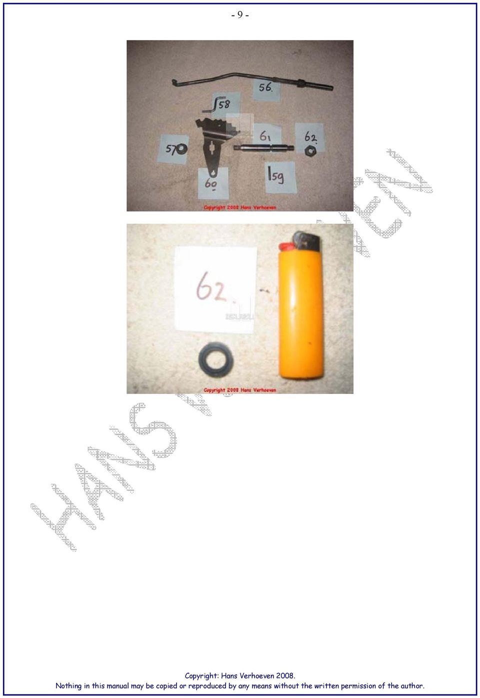
8 In the beginning there is the selector shaft assembly Lets start with a simple job: We re going to install the selector shaft 61 into the main case 36. Install selector shaft seal 62 using petroleum jelly. Assemble parking lock actuator assembly 56 and the parking lock and range selector lever 60. Then using parking lock lever nut 57 install this into the main case 36. Install spring pin 59 without pushing it completely in. Forget about link 58 at this stage. It will come much later when installing the valve bodies.

9 - 9 -
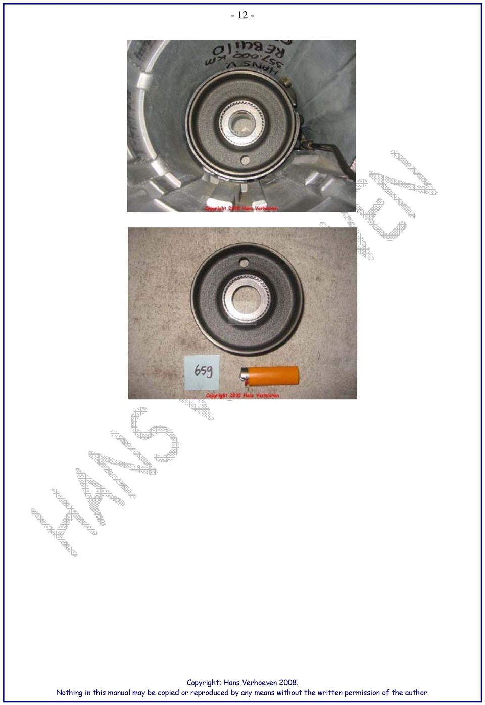
10 Assembly of the Internal Components Next step is rotating the main case 36 to vertical. Install brake band 664 and line up the servo pin area with the hole.

11 Install thrust bearing 675 using petroleum jelly Install brake or reaction sun drum 659 inside the brake band664.

12
13 We re going to do some planetary indexing on the Ravigneaux.... Sounds good to tell your grandchildren, but it s actually an important step. If you read and follow this procedure you can save yourself a lot of frustration. If you look carefully at the picture below you can see 2 different ID marks. I ve painted them yellow for your convenience. One has only a single yellow mark (top right and bottom left) while the other has double yellow marks (top left and bottom right). With a magnifying glass you must be able to find similar spots on the teeth of the pinion gears. Beware they are sometimes very hard to find! Align the ID marks on the long pinions to the corresponding marks on the front of the carrier 653. Without the right alignment it s impossible to assemble the planetary carries assembly 653 on the reaction sun gear 658 and not using a sledgehammer. Once the teeth are lined up with the ID marks slowly and WITHOUT force slide the reaction sun gear 658 onto the planetary carries assembly 653.

14 Next thing to do is drop the planetary carries assembly 653 into the main case 36 on top of thrust bearing 675.

15 Time for a check Sticking a screwdriver or similar through the servo pin hole and hold the brake band 654 in place. Then turn the planetary carrier a couple of times and check if the ID marks still line up. Install output shaft/input sun washer 652 and THEN the output shaft/input sun bearing 651 on top of the planetary carrier using some petroleum jelly.

16 The third clutch assembly.. Start with installing the 3 rd clutch inner piston seal 635 on the 3 rd clutch drum 634 inner piston using petroleum jelly. Make sure the seal isn't upside down. The biggest diameter of the conical shaped seal should be facing the drums bottom.

17 Install 3 rd clutch outer piston seal 637 on 3 rd clutch piston 638 using petroleum jelly. Make sure the check ball in piston 638 is moving freely by shaking it. A drop of clean ATF on the check ball wouldn't hurt at this stage.

18 Grease inside of 3 rd clutch drum 634 with some petroleum jelly and place the 3 rd clutch piston 638 inside the 3 rd clutch drum 634. Installing the piston 638 into the drum 634 can be hard because the new seal 637 is shaped conical and will not easily slide into the drums cylinder. Use a little hooked tool or similar to work around the edges to work the seal in. NEVER USE EXCESSIVE FORCE! Place the 12 piston clutch springs 611 on 3 rd clutch piston 638.

19 Place 3rd clutch springs seat 639 on the just installed 12 springs. Install retaining ring 640 on inner piston while compressing spring seat 639 down. Make absolutely sure the retaining ring is falling within the cavity of the spring seat. As I do not have the correct tool to do this I made up my own sophisticated spring compressor. Made of plywood and using a vice it made the job easy. Remember to put some soft material between the vice and the drum.

20 Install 3rd clutch cushion ring 641 inside 3 rd clutch drum 634. Assemble steel clutch plates 642 and lined clutch plates 643 into a stack.

21 The correct order: steel - lined - steel -lined - steel- lined - steel- lined - steel - lined. That's 5 steel plates 642 and 5 lined plates 643. Plates are soaked in fresh ATF overnight. The fifth lined plate touches the sprag race assembly 647. Not all models of the 4L30E have a fifth lined plate, but only 4. The thickness of my clutch pack was mm. with new lined plates.
22 Install the thrust input/sun washer 644 (the thicker one) on the inner piston of 3 rd drum clutch 634. Install input shaft/gear assembly bearing 645 on washer 644. Install retaining washer 636 on bearing 645.
23 Install sun gear 646 into the grooves of the lined plates of the 3 rd clutch assembly we've just put together. Make sure the grooves of the plates are "in line" with each other. NEVER use force to bring the sun gear all the way down.
24 The sprag race assembly where it can all go wrong! here and read the very carefully. The SPRAG RACE assembly: The unit is made up out of 4 parts. 1. the cage assembly The race Both retaining rings 649.
25 The following is a matter of trial and error. Before you can put the complete sprag unit on top of input sun gear 646 you have to make ABSOLUTELY sure the sprag 650 is assembled in the proper way and can turn in the right direction only. Installing it the wrong way around will be a disaster like event. What happens if you do install it the wrong way is the following: 1. The car will not have reverse. 2. It even will not have first gear except in manual 1st or 2nd gear. 3. As soon as the trans will shift to 2nd gear the trans is a... So lets do it right here the first and only time! Install one of the copper retaining rings 649 in the sprag race 647. Then install sprag cage 650 into the sprag race 647 Put the second retaining ring 649 on top of the sprag cage 650. Install the complete sprag race assembly 647 on the sun gear 646. Have a look at the three pictures on the next page..
26 I ve dedicated this single page to this to underline the importance of it
27 If you have no access to these pictures, read carefully the instructions below. Hold the teeth of the sun gear 646 in your LEFT hand. Put the thumb of your RIGHT hand on the TOP of the sprag race assembly 647. While holding the teeth of the sun gear 646 the sprag race assembly 647 the should only rotate towards you. Trying to turn it in the opposite direction will result in the sprag rage assembly 647 holding or blocking. Make absolutely sure you get this right!
28 Next install the sprag retaining ring 648 around the sprag race 647. Gently insert, not force, sun gear 646 and sprag race assembly 647 into the 3 rd clutch drum 634. When the retaining ring 648 touches the drum 634 you are almost done, but there's another thing to do and it's just a little bit tricky. The sprag retaining ring 648 needs to be pushed into the groove of the sprag race 647 before it can be pushed way down in to it's final position. I used 2 small screwdrivers while having the complete 3 rd clutch assembly held in a vice. It might give you some headaches but eventually it will work.
29 The second clutch drum. Take the 2nd clutch drum 618 and install the new inner seal 620 using petroleum jelly. Carefully slide on the new seal 620 in the right direction. The lip of the V shaped seal should be facing the bottom of the 2 nd clutch drum 618. Take care you do not damage the seal while installing it. It's not the easiest seal to install. Once you have it on carefully check all the way around it for proper seating. Install the piston outer seal 621 on the 2 nd clutch piston 622 using petroleum jelly.
30 This is a good time to see if the little check ball in the piston is freely moving. Just shake it and you should hear it rattle. The 2 nd clutch piston 622 can now be installed in the 2 nd clutch drum 618. Take care not to damage the new seals. Use petroleum jelly.
31 Place the 22 piston springs 611 on the 2 nd clutch piston 622. Place 2 nd clutch spring seat 623 on top of the springs 611. Compress the 22 springs 611. I used a vice and two bits of plywood.
32 Careful tighten the vice and guide the clutch spring seat 623 over the edge of where the retaining ring 613 is going without damaging it. Install the retaining ring 613 and make sure the ring is fully inserted.
33 Assemble the 2nd gear clutch pack: Start with waved plate 625 on top of the 2nd clutch piston 622. As with the 3rd clutch assemble steel plates 626 and lined plates 627 into a stack. The correct order is: steel - lined - steel -lined - steel- lined - steel- lined - steel - lined - steel. That's 6 steel plates 626 and 5 lined plates 627. Plates are soaked in fresh ATF overnight. The thickness of my clutch pack was mm. with new lined plates. Some 4l30E models have a second waved plate 625 on top of the clutch pack, thus between plate 626 and the 2nd clutch spacer 628. Install the assembled 2nd clutch pack into the 2nd clutch drum 618.
34 Now place the 2nd clutch spacer 628 on top of the plates. Install retaining ring 629. Install ring gear 630.
35 And finally the other retaining ring 629 to hold the ring gear 630 in place. Carefully inspect the seating(s) of the retaining ring(s) 629. The whole 2nd drum assembly should fit without applying any pressure.
36 Time to put in the 3rd clutch assembly in the waiting main case. Maybe a final check on the planetary carrier 653 that's already installed. Also double check if the washer 652 and bearing 651 are still present. After the 3rd clutch drum assembly is installed turn both the shaft of the 3rd drum assembly as well as the shaft of the planetary carrier a couple of times in both directions. This will ensure proper fit of what is assembled up to now and will also give you a double check on the correct alignment of the teeth in the planetary carrier 653 again. Painting them yellow would have been helpful right now to identify them. Unless you've already done so, get a torchlight.
37 Put in thrust washer 632 (the manual here mistakenly calls it 623) with some petroleum jelly to hold it in place. The 3 tangs should be sticking upwards. Next put thrust washer 631 on top of thrust washer 632 using the good old petroleum jelly.
38 Installation of the 3 rd clutch assembly into the 2 nd clutch drum. Align the teeth of the lined plates 627 with each other before trying to slide it on to the 3rd clutch assembly. Just slide it in without any kind of force. The grooves of the 3rd clutch assembly will easily slide onto the lined plates 627 of the 2nd clutch assembly. Carefully slide it in further until the teeth of ring gear 630 slide on to the teeth of the planetary carrier 653. An alternative method of this somewhat cumbersome procedure would be to install the 3rd clutch pack into the 2nd clutch pack BEFORE putting it in to the main case. You can do as you prefer. Not sure what the manual says about it either. Just remember to keep the teeth on the planetary carrier 653 aligned. I followed this alternative way and found it easier. Make sure the 3rd clutch pack is all the way in to the 2nd clutch pack.
39 It's now time to determine the "final end play". This requires the specialized tool J A. As I don't have or was able to have a lend of it I have used the dimension of the old selective thrust washer 12. Mine was broken as they apparently often do so I had to make one myself. A word on thrust washers: They come in six different sizes and are made of some sort of plastic material. They re to be distinguished by a different color representing the thickness. Yellow 0.15 mm mm. (0.060 in in.) Red 0.17 mm mm. (0.067 in in.) Black 0.19 mm mm. (0.075 in in.) Natural 0.21 mm mm. (0.082 in in.) Green 0.23 mm mm. (0.090 in in.) Blue 0.25 mm mm. (0.097 in in.) My home made one is somewhat in the middle range of them. I cut some grooves on both sides to get a better oil flow around it.
40 Lets get on to the reverse clutch. Slide the reverse clutch pressure/selective plate 617 into the main case. The notch on it should be positioned in the 11 o'clock position. See the arrow on the picture. Next take one (or all) of the reverse steel clutch plates 615. Take extra caution here. If you take a good look at them you will see that they have a groove on one of the notches. They must be installed with the groove at the lowest point of the main case. I believe this is to ensure proper oil flow through the oil channel in the bottom of the main case 36. See the next picture
41 Start putting the reverse clutch plates 615 and reverse lined plates 616 together. The correct order: steel - lined - steel -lined - steel- lined - steel- lined - steel. That's 5 steel plates 615 and 4 lined plates 616.
42 Finally put the waved plate 614 on top op the rev clutch steel plate 615. Take care not to block the oil flow by putting one of the three notches of the waved plate 614 on the lows point of the main case. Plates are soaked in fresh ATF overnight. The thickness of my clutch pack was mm. with new lined plates. Take the reverse clutch piston 610 and install the inner seal 608 and outer seal 609 with petroleum jelly. Be careful not to damage them.
43 - 43 -
44 The center support assembly Before we can continue to put install the reverse clutch pack we need to work on a few other things. Start gathering the pieces for the next step. Adapter case 20. Oil restrictor 27 (only if you have one, otherwise just forget about it). Both gasket transfer plate to adapter 28. Transfer plate adapter to center support 29. The center support 30. And the 8 center support screws 31. Make sure you pick the right gaskets here as most likely you will find a second set in your repair kit. Line up the holes on the gaskets and compare it with the steel plate 29. Holding them against the light proved easy to find the differences and determine the right ones. Once you have found the right gaskets you can use petroleum jelly to "grease" the adapter case (20) grooves/surfaces.
45 Then stick on the transfer adapter/center support steel plate 29, followed by the second gasket 28. Again use petroleum jelly. Put on the center support 30. On the back of it you can see a hole just over 6 mm. This hole should be in the (almost) 1 o'clock position when installed on the adapter case 20. Use petroleum jelly.
46 Use the eight screws 31 to fix the center support 30 on the adapter case 20. Trust me, you can not do this wrong. The positioning of the eight screws 31 won't allow for it. Once the eight screws 31 are in you must use your torque wrench to tighten them. The manual says 25 Nm. (that s 18 Ft Lb. or 216 in. lb). Do this in a pattern as you would tighten the bolts of your tires while stepping up the torque. see picture.
47 Installation of the reverse clutch piston. Next drop in the reverse piston 610 (remember the new seals 608 and 609). Gently twisting and turning the reverse piston 610 will eventually drop it in. Use petroleum jelly. It's time for the 24 springs 611. Yeehaa, finally. Place all 24 springs 611 into the slots on the inside the reverse piston 610. Put the spring seat 612 on top of them. Compress the 24 springs 611 and install the retaining ring 613 on the shaft of the center support.
48 It's time for a little MacGyver. MacGyver is an old TV show but if you're my age you might even remember Mannix. Compressing those springs might take about 60 kg. to 80 kg. (132 to 176 lb) or even more and I found it is the hardest part of putting together the transmission. If you don't have the proper tool, or a enormous vice, the next thing that came to my mind was myself. I've gained some weight lately for this purpose. Make a little wooden bridge with the 2 poles about 100 mm. (about 4 in) apart. The height of them enough to freely move your hands under it. 170 mm. (6.5 in) for that matter. Place your bridge tool on the spring seat 612 and lean with your chest on it. Doing this on the ground proved to be the easiest. Voila, springs compressed while having two hands available for the retaining spring to put on.
49 Install the two new oil seal rings 32 on the shaft of the center support assembly. Petroleum Jelly! Put the thrust selective washer 12 in place. (my home made one) with petroleum jelly.
50 Install o-ring/seal 8 using petroleum jelly! Although the manual shows an actual o-ring/seal 8, the one that came in my rebuild kit was rectangle shaped and proved to work fine. Also look at the drawing of seal locations. Put the two oil seals 33 on the main case with petroleum jelly. These two o-rings seal the channels between the two oil pans. Finally "grease" up all the contact areas between the main and adapter case with petroleum Jelly. Especially the big seal 28 and the aluminum edges of both cases.
51 An engagement is coming up. And it s the promise of marriage between trans and car. But for now we don t look further than the main case and adapter case. There s a lot of work left to do! Slide the adapter case into the main case taking care not to damage the oil seals 33 and just leave it like that for now. You can three of the long converter housing to main case screws 4 here as a guide. Be carefull not to damage the gasket and seal.
52 The overdrive internal components. Place the two new inner and outer 4th clutch piston seals 533 and 534 on the 4th clutch piston 532 using petroleum jelly.
53 Just when you thought your problems were over... cursing is now allowed. Just when you thought your problems were over... cursing is now allowed. Use petroleum jelly on all the surfaces where the clutch piston 532 is going to touch the surfaces of the adapter case. Then get special tool J What? You don't have one. Relax, neither did I. Now put on your women s face and play this very gently. Place the 4th clutch piston 532 into the adapter case 20.and work the piston down as far as you dare to push it. Then stop! It is crucial not to apply to much force here as it can easily damage the just installed piston seals 533 and 534. Remember you're a woman now. Get a 0.06 cm. (0.02 in) feeler gauge and work the outer seal 534 very gently into the adapter case 20. Go around in very short steps. You can actually feel the seal 534 sliding into or between the piston and the adapter case. Once you have worked around completely you are able to push the piston just a little bit further downwards. The inner seal 533 is even a bit harder to get on to the "cylinder". This one took me the better part of an half an hour, but I finally managed with the same method as the outer seal 534 and the use of the same feeler gauge. The design of this inner seal 533 was newly designed by the engineers of Transtec. The inner seal was made "D" shaped for easy installation.
54 Finally it s in! Place the retainer and spring assembly 531 with the retainer facing upwards inside the 4th clutch piston and install the snap ring 530. Ensure it is completely fitted into the groove.
55 Stick in the thrust washer for the internal gear/support 529. Tangs facing down. Use petroleum jelly to prevent it falling out.
56 The overdrive clutch assembly. You need the following parts: Overrun clutch housing 510. Overrun clutch piston 513. Overrun clutch release spring 514. Release spring retainer 515. Roller assembly 516. Overdrive roller clutch cam 517. Snap ring for the overrun clutch hub 518. Note that some older models have a separate piston and seals. They are separately numbered 511, 512 and 513 in the GM s manual. Start with rattling the overrun clutch housing 510 to hear the check ball.
57 Place the overrun clutch piston 513 into the overrun clutch housing 510 using petroleum jelly. Install overrun clutch release spring 514 with the "springs" upward. Place release spring retainer 515 with the rim upwards.
58 Then the roller assembly 516 goes on top of the release spring retainer 515 in such a way that the overdrive roller clutch cam 517 can be installed after this, check if all of the ten rollers are present! Gently put the overdrive roller clutch cam 517 in the roller assembly 516. Compress the assembly and install the snap ring for the overrun clutch hub 518.
59 For compressing I use two same length pieces of timber and a tie rip.
60 It's plate time again! You need the following parts: One waved overrun clutch plate 520. (not on all models). Two steel overrun clutch plates 521. One lined overrun clutch plate 522 (although some models have two plates, I have only one). One thicker steel backing plate for the overrun clutch 523. One snap ring for the overrun clutch housing 524. Start by putting the waved plate 520 into the overrun clutch housing. Build up the clutch pack containing steel, lined and backing plate 521, 522 and 523. The correct order: steel - lined - steel - backing plate.
61 Plates are soaked in fresh ATF overnight. Some 4L30E's have an extra lined plate 522 in them. The thickness of my clutch pack was only 6.52 mm. without the backing plate 523 and mm. including the thicker backing plate 523. Put some extra attention to this backing plate 523. It is supposed to be installed with the "UP" mark on the outside of the clutch pack. See picture. Install snap ring 524 onto the overrun housing.
62 The overdrive sun gear Next step is to install the overdrive sun gear 519. If you carefully look at it, is has a shiny and a darker side with teeth marks of the snap ring 524. The shiny side has to go into the overdrive carrier assembly 525. Below you ll find a picture of the overdrive sun gear 519. Note the blue ribbon I put through one of the oil ports for easy identification. Place the overdrive carrier assembly 525 onto overdrive sun gear 519 i.e. on top of the assembled overrun clutch. The overdrive carrier assembly 525 comes as a prefabricated part. Notice the bearing on the inside and give it some fresh ATF before you install the unit on the sun gear 519.
63 On to that big rod The turbine shaft. You can finally get that long steel rod called the turbine shaft 506. Strip off the three oil seals 508 and seal 505. Install the three oil seals 508 with some petroleum jelly. Wait to install oil seal 505 as it has to go on later. Now gently slide the turbine shaft 506 into the overdrive assembly starting from the overrun clutch housing 510 side and slide it all the way through. One of the oil seals 508 should disappear into the housing 510 leaving just two visible. Install snap ring 526 on the turbine shafts end. (on the carrier assembly 525 side).
64 Put thrust bearing 527 on top of the overdrive carrier assembly 525 in a way the turning inner part is touching the carrier 525. Stick the overdrive internal gear 528 on the overdrive carrier assembly 525 while having the teeth greased with fresh a dab of petroleum jelly. Note that the overdrive internal gear 528 only turns counter clockwise and blocks in the opposite direction. This is what it is designed to do. I am not getting to technical here as we're only rebuilding a trans. Make sure thrust washer 529, the one with those two tangs, is still on the bottom of the adapter case. You can now put the whole assembly into the adapter case.
65 The 4th clutch assembly. The 4th gear clutch pack has four steel plates 502 and only two lined plates 503. The correct order: Steel - lined - steel - steel - lined - steel. That's 4 steel plates 502 and only two lined plates 503. No it's not a typing error, there are indeed two steel plates on top of each other, although some models of the 4L30E have an extra lined plate. Mine hasn't. First find out how the steel plates fit in to the adapter case. Tip: the shallowest notch goes in the 5 o'clock position.
66 Lower the stack of plates into the adapter case. Plates are soaked in fresh ATF overnight. The thickness of my clutch pack was mm. with new lined plates. Put the 4th clutch retainer 501 on top of the clutch pack with the approximate 30 mm wide (just over 1 in) cavity at the six o'clock position facing upwards. That is towards you.
67 The oil pump assembly. Lets start putting the oil pump assembly back together. But first a little lecture. As always assemble all parts with petroleum jelly. Most of the parts like valves and sleeves have a tight fit. By now you should have cleaned them thoroughly with rags, compressed air and a cleaning agent. There is no need to use any significant force on any of the parts. The use of excessive force is more likely to do damage. At this stage I am not going to describe every single part and how it should be put together. If you're still reading this you must either be a nerd or desperate. It should be easy enough for you to find out by looking at the pictures and drawings. For the assembly of the oil pump we need the following: 1. Pressure regulator assembly (parts )
68 Converter clutch control valve (parts ) 3. Throttle signal accumulator assembly (parts )
69 Once you have put all these parts into the oil pup assembly 209 you can install the two oil pump drive gears 201 and 202. Done with that? Easy enough wasn't it. Took me less than 5 minutes.
70 Ring the bell, it s time for the bellhousing. To be correct it's not a bell housing but a converter housing. But who cares. Get that cleaned salad bowl 6 on your workbench and put some petroleum jelly on the areas where the pump is going. Place the oil pump body wear plate 9. You can not install this one wrong. The holes for the screws won't match up if you tried. What s that part just left of the screwdriver.....?
71 Stick on the oil pump assembly with the arc at the 12 o'clock position facing the wear plate 9. Again, this one can't be installed wrong either. Turn the converter housing 6 on its side and install the five screws holding the oil pump assembly 10. Go hand tight (loose) for now. DO NOT install the converter housing ring seal 3 yet. Turn it all back over again and try if you can "wiggle" the converter housing 6 on the oil pump assembly 10 by a few mm. It should have a loose fit for reasons explained later.
72 Install seal 8 around the pump and stick on gasket 11 using petroleum jelly.. Another word on so called "end play" is in place here. You could or maybe even should use special tools J and J here. I don't have them, and therefore have no way to determine the end play. I only re-install here what I have taken out when disassembling the tranny. Place the thrust selective washer 12 on the oil pump assembly. Use petroleum jelly to hold it in place while you turn over the converter housing 6. Don't forget to tighten the converter housing plug 7. An interesting little screw that blocks of one of the main ATF flows. Need to do some research on it. Before you can put the assembly together you might have a look at where the actual holes for the seven long screws 4 are. One is located in a not so obvious spot at the bottom of the adapter case 20. There are two more holes where you would expect to fit more screws 4. One is at the somewhat 1 o'clock position, the other at 8 o'clock. DO NOT stick screws in here. Especially the one on the 1 o'clock position has the adapter case gasket on the bottom just waiting there to be punctured by you. Don't think that it would harm anything, but better safe than sorry.
73 Installation of the convert housing on the adapter case. Slide the converter housing 6 and oil pump assembly 10 on the vertical standing adapter case 20. Use two or better three of the long screws 4 as a guide. REMEMBER: Be careful not to damage gasket 11. Once the converter housing 6 is installed on the adapter case 20, take the remaining screws 4 and slide them into the converter housing 6. It's a good idea to put petroleum jelly on them. Hand tighten all the seven screws 4. Get seal 3 and put petroleum jelly on all it's surfaces. DO NOT try to tap it into place using a hammer or similar. Just use the three screws 2 to EVENLY work it all the way down in it's seat. Check if the converter housing is still a bit loose.
74 For the final stage get the torque converter 1. By this time you should have flushed it a couple of times with clean ATF. As you cannot easily open it up and give it a good clean, there s probably a lot of dirt on the inside. I tried to empty it by constantly shaking and turning the inside pressure plate and stator assembly. When it was almost empty I filled it up with half a liter (about half a quart) of fresh ATF and started all over again. I did this for a couple of days. Grease up the splines on the oil pump shaft and slide the torque converter 1 onto the oil pump shaft. Ensure that the converters shaft is fully seated on the oil pump shaft and give it a couple of turns and very gently take it of again. Then start to torque up the seven long screws 4. Torque to 40 Nm. (30 Ft lb or 360 In lb). Go in increments of 10 Nm. ( 7.5 Ft lb or 90 lb in). And don t forget to tighten in a nice pattern. In case you wondered... what about the oil pump screws? Finally put in the torque converter one more time, give it a couple of turns, take it out and start to torque up the five screw 5 for the oil pump 10. They need 20 Nm. (15 Ft lb or 180 in lb). All left to do is the little oil seal 505 on the turbine shaft.
75 The accumulator piston assembly. Put the whole transmission on your workbench facing the valve bodies side up. The parts needed here are: 13, 14, 15, 16, 17, 18, 19. Put the new ring 19 on the accumulator piston 18. Use petroleum jelly. Put the two o-ring seals 15 into the adapter case 20 Using petroleum jelly. Assemble the rest of the unit. Refer to the pictures and drawings.
76 For compressing the stiff accumulator piston spring and installing the snap ring 13 I used ordinary human power. Below are extra pictures to guide you. Note: Use petroleum jelly for installation and on the new seals and o-rings.
77 The servo piston assembly. The fourteen parts needed are 90, 91, 92, 93, 94, 95, 96, 97, 98, 99, 100, 101, 102 and 103. Put the new steel piston ring 98 on the servo piston 97. Rotate the output shaft of the planetary carrier 653 counter clockwise as seen from the back end of the main case 36 to ensure the brake band 664 is in the right position to match up with the apply rod 102. You can also do a visual check by peeking through the servo piston hole on the bottom of the main case 36. Slide the apply rod 102 into the adjust sleeve 101 and put the spring seat cushion 100 onto the rod. Put the servo piston screw 96 only a few turns into the adjust sleeve 101. Make sure that the rounded tip of the apply rod 102 is going to touch the brake band 664.
78 Next one up is the (biggest) servo piston return spring 103 and the smaller servo piston cushion spring 99 which goes inside the bigger servo piston return spring 103 and rests on the spring seat cushion 100. Be careful with the new steel servo piston seal 98. Use a little flat screwdriver to work it into the cylinder.
79 Press on the servo piston 97 to install the retaining ring 93. I used this rather unconventional method of compressing the servo piston 97. Using two of the valve body screws 70 and a hacksaw. You can devise your own way of doing it, but for me it worked rather well. Notice the two valve body screws 70 to hold down the hacksaw. Install the servo piston clip 94 and servo screw nut 95. You might have to pull the servo piston adjust sleeve a little bit out. IMPORTANT: YOU MUST USE A TORQUE WRENCH TO DO THIS NEXT STEP. We are going to adjust the brake band 664 by tightening the servo adjusting screw 96. Adjust the torque wrench to EXACTLY 4.5 Nm (3.33 Ft lb or 40 in lb) and tighten the screw 96. Once you have done this BACK OFF the screw 96 EXACTLY FIVE TIMES. Then tighten up the servo screw (locking) nut to 18.5 Nm (13.65 Ft lb or 164 in lb) while holding the servo adjusting screw 96. We're done for now. Don't put the gasket 92 and cover 91 on yet.
80 The extension case assembly Before we start on both the valve body's we're going to the extension assembly. Parts needed are: Breather pipe 37 Breather pipe o-ring 38 Reservoir 39 Extension case gasket 42 Extension case 43 Speed sensor seal 44 Speed sensor 45 Extension assembly seal 50 Extension to main case screws 52 Parking lock pawl spring 53 Parking lock pawl 54 Seal parking lock wheel 667 Parking lock wheel 668 Speedo wheel 672 Retaining ring 673 First put in the reservoir 39. Then install the breather pipe 37 and o-ring 38. The breather pipe 37 holds the reservoir 39 in place, and that s exactly the reason you couldn't get it out in the first place
81 Next install a new steel seal ring 667 on the parking lock wheel 668 and hooking the two ends of the seal together. Use petroleum jelly. Use a small flat screwdriver to "work" the seal into the case. Insert the parking lock wheel 668 into the main case. Use petroleum jelly to grease all the surfaces prior to installation. If it is completely inserted the wheel should be sticking out of the main case approximately 14 mm. (0.55 in).
82 Slide the speedo wheel 672 onto the output shaft. Use petroleum jelly. Install the retaining ring 673. On the picture below it s hard to see, but you can just identify one of the little holes in the retaining ring 73.
83 Let s get on to the actual extension housing 43. Install parking pawl lock spring 53 and Parking lock pawl 54 in extension housing using petroleum jelly Stick the extension case gasket 42 on the extension case 43 using petroleum jelly. Install the extension case 43 on the main case. Use the seven extension to main case screws 52 and tighten up to 32 Nm. (24 Ft lb or 288 in lb) Push the parking lock pawl 54 a little out of the way to make room for the parking lock actuator 56.
84 Not covered by the manual are the two steel pint that line up the extension housing with the transfer case. Keep them with the extension case 43.. Last thing to do here is to put in the extension case seal 50. Install it with the "closed" side outwards (i.e. towards the transfer case) Use the red loctite on the outside and petroleum jelly.
85 The adapter case valve body. As with the oil pump assembly, I am not going to describe into detail every part. Use the pictures and drawings as a reference. We start with the adapter case valve body. Parts you need: Adapter case electrical connector 22 Screw and washer assembly 23 Adapter case bottom pan gasket 68 Adapter case harness assembly 69 Valve body screws 70 Adapter valve body gasket 72 Adapter valve body transfer plate 73 (steel) Adapter case to transfer plate gasket 104 Check ball 317 (only one) Adapter case valve body 401 Solenoid force motor screw 402 Force motor retainer 403 Force motor solenoid accumulator plug 405 Spring pin accumulator valve accumulator control valve spring 408 (optional, but it's in mine) 3-4 accumulator control valve 409 Feed limit valve spring 410 Retainer ring 411 Feed limit valve 412 Plug filter seal 413 Screen plug 414 Force motor screen assembly 415 Torque converter clutch ON/OFF solenoid N.C. 416 Washer for the TCC solenoid 417
86 At this point it is easiest to have the complete transmission upside down on your workbench. First put check ball 317 in the right spot on the adapter case. See picture for the correct location. Stick adapter case to transfer plate gasket 104 on the adapter case using petroleum jelly.
87 Next to go on is the steel adapter valve body transfer plate 73. Use petroleum jelly. On top of the steel adapter valve body transfer plate 73 goes adapter valve body gasket 72. Again using petroleum jelly.
88 Assemble the rest of the adapter case valve body 401. Take extra care not to break the plastic connectors on the solenoids. After the plastic has been immerged in ATF for a couple of years, sixteen in my trans, I have found the plastic become a little brittle and easily to break. A new solenoid will easily set you back a couple of hundred dollars. So be gentle on them. Take a good look at the pictures and drawings for details. Change the o-rings and seals on the solenoid 416. There are a inner and outer o-ring which vary slightly in diameter. Change o-ring 413 on the screen plug 414.
89 Next runner up is the feed limit valve 412. Then the 3-4 accumulator assembly. Spring 408 is optional, but if it s there put it back in.
90 Followed by the solenoid force motor 404. The assembled adapter case valve body 401 should look like this by now.
91 Before sticking the adapter case valve body 401 the wiring harness has to go in place. Route it through the channel in the adapter case before you put the completely assembled adapter case valve body 401 on the adapter case. Stick in the seven screws 70 and hand tighten them. Use a torque wrench set to 20 Nm. (15 Ft lb or 180 in lb) and tighten the seven screws 70. Don't forget to set your torque wrench back to zero after using it. Connect the harness to the solenoid and force motor. For the torque converter clutch ON/OFF solenoid N.C. 416 or TCC in short you can't go wrong. Don't forget single the negative ground connecter (white) Force motor 404 link up: only two wires, blue and yellow. Put the yellow wire on the outermost connector and the blue on the inner. Put a new seal on the adapter case electrical connector 22, then push it in it's position from outside the adapter case 20 carefully aligning that little notch into the cavity.
92 Connect the adapter case harness assembly 69 and the adapter case electrical connector 22 plus that little plastic protector without a name.
93 Have you noticed the Fluid temperature sensor in the harness? It's a temperature sensitive resistor (actually a thermistor) Finally the adapter case bottom pan gasket 68 with some petroleum jelly. and the adapter case bottom pan 67 with the 12 screws 23.
94 Here you can see a couple of old magnets. They came from an old computer hard drive and are at least five times stronger than the original magnet. Just later I decided the best place for those two extra magnets would be on the outside of the adapter case bottom pan 67 as the strength of the magnets might influence the working of the electrical parts on the inside of the pan. Just my two cents.....
95 The main valve body assembly. There s a big part list here to work with, but relax, most of them can t go in wrong. Parts needed: Sixteen screw and washer assembly 23 Electrical connector main case 55 Manual valve link 58 Twelve valve body screws 70 Bottom pan main case gasket 75 oil filter 79 Main case harness assembly 80 Manual detent roller and spring assembly 82 Main valve body to transfer plate gasket 86 Main valve body transfer plate 87 (steel) Transfer plate to main case gasket 88 Two transfer plate on valve body screw 89 Main case valve body 301 Three spring pin 302 ON/OFF solenoid assembly & 3-4 shift valve 304 Two 1-2 & 3-4 shift spring 305 Two Valve retainer 306 ON/OFF solenoid N.O assembly shift valve 308 Two spring pins 309 Valve bore plug 310 Low pressure control valve spring 311 Low pressure control valve 312 Three check balls accumulator control valve accumulator control spring 319 (optional, but there's one in mine) 1-2 accumulator valve 320 Waved washer for the PWM solenoid 321 (PWM = Pulse Width Modulated) PWM solenoid pin 322 (PWM = Pulse Width Modulated) Band control solenoid assembly 323 (see below for a little write up) PWM solenoid screen assembly 324 Screen plug 325 Manual valve 326
96 A few general remarks before you start. Use the pictures and drawings to work your way through the assembly of the main valve body 301. Don't forget the new o-rings on the solenoids. Use plenty of petroleum jelly on the moving parts and the cylinders of the valve body 301. Also use a little block of wood to keep the main valve boy free from the workbench. Otherwise you might damage one of the plastic connectors of the solenoids. They're prone to break easily remember. When hammering those spring pins in, avoid them sticking out of the surface of the valve body. Good luck. The clock starts now! minutes, beat that! Nah, just kidding. Take your time. Put two of the three check balls in the main case. See the picture for the right locations.
97 Next stick the transfer gasket main case 88 on with petroleum jelly to hold it in place. Take the 3rd check ball 317 and place it in the right spot on the main case valve body 301. Again, look at the picture. Use a dab of petroleum jelly to hold it in place and prevent it falling out.
98 Put the main valve body to transfer plate gasket 86 on the main case valve body 301 using petroleum jelly. The steel main valve body transfer plate 87 is next. Use the two transfer plate on valve body screws 89 to fasten the plate. Use a couple or all the twelve valve body screws 70 to get proper alignment of the plate and gaskets. Use 13 Nm of torque (9.58 Ft lb or 115 in lb) to tighten. Place the complete valve body assembly on the main case. Carefully align all the holes but don't put ANY of the valve body screws 70 in yet.
99 One of the things lying on your workbench is the manual valve link 58. Be careful not to drop it into the main case when installing it. Link up the manual valve 326 with the parking lock and range selector lever 60. The manual valve link 58 has a short and long end. The short end links to the parking lock and range selector lever 60, the long end fits in the drilled hole at the end of the manual valve 326.
100 Take the Manual detent roller and spring assembly 82 and position the roller on the parking lock and range selector lever 60. Now you can gently put in 9 of the twelve valve body screws 70 and hand tighten them first. Leave out the three valve body screws 70 that hold the oil filter 79. Install the Servo piston gasket 92, the servo piston cover 91 and use the four servo cover screws 90. Tighten to 25 Nm. (18 Ft lb or 216 in lb).
101 Put the main case harness assembly 80 on the main valve body 301. Pay attention to the routing of the wires. There is a "channel" cut out of the main valve body 301 to accommodate for the harness to run through. It's mainly protected and held in place by the oil filter 79. You still haven t put in the three remaining valve body screws 70. Install a new seal on the electrical connector main case 55 using petroleum jelly on both connector and main case. Gently work the electrical connector main case 55 into the main case.
102 Connect the main case harness assembly 80 to the electrical connector main case 55. Look at the picture for reference on wire colors. Now start tightening the first nine of the twelve valve body screws There should be no screws in three of the holes at this stage. They get to be done when installing the oil filter 79 just after this. Torque: 20 Nm. (15 Ft lb or 180 in lb). Install the new oil filter 79 using the three remaining valve body screws 70. Take the last of the gaskets, the bottom pan main case gasket 75 and the remaining sixteen screw and washer assembly 23. Use 11 Nm. of torque (8 Ft lb or 96 in lb) One last thing to do is the filler tube seal 26. Use petroleum jelly.
103 You might have to put in the two oil cooler fittings 34 and 35.
104 A word on the mode switch. The mode switch is located on the left hand side of the main case. No, you re not gonna find it lying on your workbench. Unless you ve taken the whole switch and harness out, it s still dangling under the vehicle. It s a good idea to clean it s internals. Unscrew the cover to expose the inner parts. Clean the inside thoroughly and re-grease the copper strips with some dielectric grease, a NON-conducting grease. Once installed you need to set the mode switch. There are two procedures you can follow. Procedure 1: Without using a multi meter. 1. Put the car in neutral. 2. Remove the selector lever from the mode switch. 3. Remove the cover. 4. Loosen the two 10 mm. mounting screws. 5. By rotating the mode switch you can line up the slot in the mode switch housing with the selector shaft bushing. 6. Insert a 2,4 mm punch (3/32 in) in the slot. 7. Tighten the two 10 mm. screws.
105 Procedure 2: Using a multi meter. 1. Put the car in neutral. 2. Disconnect the mode switch connector. It s located in front of the air filter box and it s the biggest of the three you ll find there. (black). 3. Connect a multi meter set to resistance between terminals 1 and Loosen the two mounting screws of the mode switch and find the range of electrical contact by turning the entire mode switch. 5. Then fix the mode switch to the middle of that range and tighten the two mounting screws.
106 GENERAL MOTORS Hydra-Matic 4L30-E automatic transmission Illustrated part list Following images are a reproduction from the original 1992 General Motors Corporation - Powertrain Division.
107 Case and associated parts.
108 Case and associated part list. 38. Pump assembly.
109 Main valve body. 40. Adapter valve body.
110 Overdrive internal components.
111 Internal components.
112 Internal components part list. 44. Center support assembly.
113 Bushings, Bearings & Washer Locations.
114 Seal locations.
115 The Legal Talks. This manual and any information enclosed within the manual, contains restricted and/or privileged information and is intended only for authorized screening and/or confidential presentation at the author s discretion. If you are not the intended observer of this manual, you must not disseminate, modify, copy/plagiarize or take action in reliance upon it, unless permitted by the author of this manual. None of the materials provided in this manual may be used, reproduced or transmitted, in any form or by any means, electronic or mechanical, including recording or the use of any information storage and retrieval system, without written permission from the author. If you received this manual in error please notify the author immediately. ([email protected]) The confidential nature of and/or privilege in this manual enclosed is not waived or lost as a result of a mistake or error in this manual. The author accepts no liability whatsoever, whether it was caused by: 1. Accessing or other related actions to this manual. 2. Any links, and/or materials provided/attached to this manual. The author assumes that all users understand risks involved within this manual and/or its attached materials. All rights reserved. All other brands, logos and products are trademarks or registered trademarks of their respective companies. For more information, see the Copyright Act. Complied by Hans Verhoeven First published in April 2008 By Hans Verhoeven New Zealand
Rebuild Instructions for 70001 and 70010 Transmission
 Rebuild Instructions for 70001 and 70010 Transmission Brinn, Incorporated 1615 Tech Drive Bay City, MI 48706 Telephone 989.686.8920 Fax 989.686.6520 www.brinninc.com Notice Read all instructions before
This is the civilian transfer case with the cooling loop only found in the driven gear half of the front case.
 INTRODUCTION The Transfer case used in the AMG Hummer is a New Venture Gear, model 242. This case has been in use for the H-1/Hummer since the early 1990 s. There have been modifications to the internal
AUTOMATIC TRANSMISSION
 23E-0-1 AUTOMATIC TRANSMISSION V5A51 CONTENTS GENERAL INFORMATION... 23E-0-3 1. SPECIFICATIONS... 23E-1-1 TRANSMISSION MODEL TABLE... 23E-1-1 GENERAL SPECIFICATIONS... 23E-1-2 SERVICE SPECIFICATIONS...
Char-Lynn Hydraulic Motor. Repair Information. 10 000 Series. October, 1997
 Char-Lynn Hydraulic Motor October, 1997 Repair Information Geroler Motor Two Speed 001 27 Retainer inside bore of valve plate bearingless motors only 4 15 16 3 6 35 Parts Drawing 25 2 2 1 19 17 36 40 47
STEERING SYSTEM - POWER
 STEERING SYSTEM - POWER 1990 Nissan 240SX 1990 STEERING Nissan - Power Rack & Pinion Axxess, Maxima, Pulsar NX, Sentra, Stanza, 240SX, 300ZX DESCRIPTION The power steering system consists of a rack and
TRANS-05, Torque Tube Removal, Rebuilding, and Installation
 TRANS-05, Torque Tube Removal, Rebuilding, and Installation Tools Metric Wrench Set Metric Socket Set Jack Stands (6 minimum) Floor Jack 8mm Cheesehead socket (also referred to as 12 point internal socket
Mercedes 722.3 722.4
 96 Mercedes 7. 7. 5 6 7 8 - Clutch K - Brake Band B - Disc Brake B - Wide Planet Pinion 5 - One-Way Clutch F 6 - Clutch K 7 - Brake Band B 8 - Narrow Planet Pinion Int. Band Fwd. Band Rev. Clutch Direct
MANUAL TRANSMISSION CONTENTS ...
 22D-0-1 MANUAL TRANSMISSION CONTENTS GENERAL INFORMATION... 22D-0-3 1. SPECIFICATIONS... 22D-1-1 TRANSMISSION MODEL TABLE GENERAL SPECIFICATIONS SERVICE SPECIFICATIONS TORQUE SPECIFICATIONS............
Trillium 40 Axis Spring Tensioner Wire Replacement Instructions
 Trillium 40 Axis Spring Tensioner Wire Replacement Instructions 1 Overview The objective is to replace the broken axis spring tensioner wire. This requires the following tasks: 1. Remove the seismometer
ARTICLE BEGINNING APPLICATION IDENTIFICATION DESCRIPTION LUBRICATION & ADJUSTMENT TROUBLE SHOOTING. MANUAL TRANSMISSIONS Saab 5-Speed Transaxle
 Article Text ARTICLE BEGINNING MANUAL TRANSMISSIONS Saab 5-Speed Transaxle APPLICATION TRANSMISSION APPLICATION ÄÄÄÄÄÄÄÄÄÄÄÄÄÄÄÄÄÄÄÄÄÄÄÄÄÄÄÄÄÄÄÄÄÄÄÄÄÄÄÄÄÄÄÄÄÄÄÄÄÄÄÄÄÄÄÄÄÄÄÄ Vehicle Application Transmission
http://waterheatertimer.org/troubleshoot-rheem-tankless-water-heater.html
 http://waterheatertimer.org/troubleshoot-rheem-tankless-water-heater.html TECHNICAL SERVICE DEPARTMENT Removal, Cleaning, & Reinstallation of the Burner Assembly For models 74 & GT199 Required tools -
Drive shaft, servicing
 Volkswagen Passat B6 - Drive shaft, servicing Стр. 1 из 41 40-7 Drive shaft, servicing Drive shafts, overview I - Assembly overview: Drive axle with CV joint VL100 40-7, Drive axle with CV joint VL100,
Volkswagen Jetta, Golf, GTI 1999, 2000 Brake System 46 Brakes - Mechanical Components (Page GR-46)
") 46 Brakes - Mechanical Components (Page GR-46) Front brakes Brake pads, removing and installing Brake pads, removing and installing FN 3 brake caliper, servicing FS III brake caliper, servicing Rear wheel
46 Brakes - Mechanical Components (Page GR-46) Front brakes Brake pads, removing and installing Brake pads, removing and installing FN 3 brake caliper, servicing FS III brake caliper, servicing Rear wheel
Front axle components, overview
 just a test. Front axle components, overview 40-1 General Information Load bearing components and parts of the suspension must not be welded or straightened. Vehicles without drive axle must not be moved,
For exploded diagram and part number information, refer to the Spare Parts Catalog available on our website at www.rockshox.com.
 For exploded diagram and part number information, refer to the Spare Parts Catalog available on our website at www.rockshox.com. Information contained in this publication is subject to change at anytime
Slide the new steering column shaft through the steering column from the driver compartment.
 Slide the new steering column shaft through the steering column from the driver compartment. Push the column shaft through the steering column until the machined end is out past the column lower bushing.
2100 AD 015 0009 Mirror Elevator Ball Nut Replacement Procedure
 2100 AD 015 0009 Mirror Elevator Ball Nut Replacement Procedure Derek Guenther 1/28/2015 Rev. Purpose The purpose of this document is to describe the procedure necessary to replace one of the ball nuts
AXLE SHAFTS - FRONT. 1998 Pontiac Bonneville MODEL IDENTIFICATION DESCRIPTION & OPERATION TROUBLE SHOOTING REMOVAL & INSTALLATION
 AXLE SHAFTS - FRONT 1998 Pontiac Bonneville 1998-99 DRIVE AXLES FWD Axle Shafts - Cars - "C", "G" & "H" Bodies GM Aurora, Bonneville, Eighty Eight, LeSabre, LSS, Park Avenue, Regency, Riviera MODEL IDENTIFICATION
MGB Chrome Bumper Conversion
 MGB Chrome Bumper Conversion Installation Instructions For 1974 1/2-1980 MGB This kit requires cutting, welding, and painting. Professional installation recommended. Note: Every MGB body is slightly different
DTU Animal Cart Programme
 DTU Animal Cart Programme TECHNICAL 21 RELEASE PIPE AND ROLLER DONKEY CART AXLES Development Technology Unit, Department of Engineering, University of Warwick, Coventry, CV4 7AL UK, tel: +44 (0)1203 523523
Micrio WS1 Replacement Wind Speed Sensor and WC1 Replacement Wind Compass Sensor for Raymarine ST50 and ST60 Wind Instruments. Rev 4.
 Micrio WS1 Replacement Wind Speed Sensor and WC1 Replacement Wind Compass Sensor for Raymarine ST50 and ST60 Wind Instruments. Rev 4.1 The Micrio WS1 Wind Speed Sensor and WC1 Compass Sensor are direct
Volkswagen B3 Passat Manual Transmission 02A 34 Manual Transmission - Controls, Assembly (Page GR-34) 02A 5-speed. Gearshift cable/lever installing
 02A 5-speed. Gearshift cable/lever installing") 34 Manual Transmission - Controls, Assembly (Page GR-34) 02A 5-speed Gearshift cable/lever installing Gearshift housing repairing Gearshift lever repairing lever/relay lever, installing Gearshift mechanism
34 Manual Transmission - Controls, Assembly (Page GR-34) 02A 5-speed Gearshift cable/lever installing Gearshift housing repairing Gearshift lever repairing lever/relay lever, installing Gearshift mechanism
1/29/2008 DR50. Baja Motorsports Inc. P.O. Box 61150 Phoenix, AZ 85082 Toll Free: 888-863-2252 PART NUMBERS PRICES ARE SUBJECT TO CHANGE 1 of 45
 DR50 Toll Free: 888-863-2252 PART NUMBERS PRICES ARE SUBJECT TO CHANGE 1 of 45 CYLINDER & CYLINDER HEAD Part UPC Number Description Baja Description 1 DR50-001 842645074424 CYLINDER 1 1 2 DR50-002 842645074431
Figure 2 The fan and shroud also needs to be removed for access to the four a/c compressor bolts and removal of the compressor from the top.
 Here are some pictures to show what s required when replacing the A/C compressor, expansion valve and receiver/drier on a 2001 Volvo V70. Even if you don t replace these A/C parts these pictures can help
Step by step guide to installing your own Ku Band satellite dish
 Step by step guide to installing your own Ku Band satellite dish If you don't feel comfortable installing your own system, your local TV Aerial or Handyman can easily follow these helpful guidelines for
M A N U A L 13-10-05
 Documentation The following information sheets illustrate the description below: 12-WW01-4G-E Sectional view of the lance with main dimensions 12-W101-6G-E Sectional view of the head of the lance with
ASSEMBLY DIAGRAM AND ASSEMBLY REFERENCE ULTIMA OLD SCHOOL 2 EVO & TC BELT DRIVE UNITS
 ASSEMBLY DIAGRAM AND ASSEMBLY REFERENCE ULTIMA OLD SCHOOL 2 EVO & TC BELT DRIVE UNITS BELT DRIVE ASSEMBLIES Part# 58-850 2 Old School Belt Drive Assembly - Polished Part# 58-851 2 Old School Belt Drive
DANA 30 MANUAL HUB CONVERSION KIT
 DANA 30 MANUAL HUB CONVERSION KIT 12194 PLEASE READ AND UNDERSTAND ALL INSTRUCTIONS BEFORE YOU BEGIN Your safety and the safety of other motorists is very important. Your Jeep is an off road capable vehicle
Round Housing with Side Ports
 Power Steering Steering Control Unit (SCU) Parts and Repair Information 5 Series Steering Control Units 001 Square Housing with Side Ports Round Housing with Side Ports T E L RP Round Housing with End
TUTORIAL. REbUILdING. front CALIpER O-RING CONVERSION CORVETTE 1965-82. Part #: HT-1
 Part #: HT-1 1965-82 CORVETTE O-RING CONVERSION front CALIpER REbUILdING TUTORIAL Choosing a Brake Caliper Rebuild Kit Standard Lip Seals vs. O-Ring Seals Lip seal design seals are used on 1965-1982 Corvette
ALLDATA Online - 2006 Dodge Truck RAM 2500 Truck 2WD L6-5.9L DSL Turbo VI... Service and Repair
 Page 1 of 15 Home Account Contact ALLDATA Log Out Help PAUL REDEHOFT Select Vehicle New TSBs Technician's Reference Component Search: OK 2006 Dodge Truck RAM 2500 Truck 2WD L6-5.9L DSL Turbo VIN C Conversion
Volkswagen Jetta, Golf, GTI 1999, 2000 Brake System 47 Brakes - Hydraulic Components (Page GR-47)
") 47 Brakes - Hydraulic Components (Page GR-47) FS III front brake calipers, servicing Front brake caliper piston, removing and installing FN 3 front brake calipers, servicing Front caliper piston, removing
47 Brakes - Hydraulic Components (Page GR-47) FS III front brake calipers, servicing Front brake caliper piston, removing and installing FN 3 front brake calipers, servicing Front caliper piston, removing
Auto Sentry-eXP Maintenance
 Auto Sentry-eXP Maintenance Maintenance Procedures for Auto Sentry exp Bill Dispenser Credit Card Reader Bill Acceptor Bill Dispenser Maintenance Bill Dispenser Problem / Cause Bill Dispenser Error Codes
Parts#MB003-003 Reverse Gear MAMBA (Monoblock for Cable operated) For 5 speed Trans., '87 to '06 Big Twin models (except '06 Dyna)
 For 5 speed Trans., '87 to '06 Big Twin models (except '06 Dyna)") Installation Instructions Reverse Gear MAMBA (Monoblock for Cable operated) Read and become familiar with these installation instructions before start. Two Piece for H-D 5 Speed Trans., Cable operated
Installation Instructions Reverse Gear MAMBA (Monoblock for Cable operated) Read and become familiar with these installation instructions before start. Two Piece for H-D 5 Speed Trans., Cable operated
Table of Contents. Overview 1. Pump Disassembly 2. Control Disassembly / Reassembly 7. Pump Reassembly 13. Adjustment Procedures DR Control 19
 Table of Contents Overview 1 Pump Disassembly 2 Control Disassembly / Reassembly 7 Pump Reassembly 13 Adjustment Procedures DR Control 19 Adjustment Procedures DRG Control 20 Adjustment Procedures DFR
1/29/2008 DR70. Baja Motorsports Inc. P.O. Box 61150 Phoenix, AZ 85082 Toll Free: 888-863-2252 PART NUMBERS PRICES ARE SUBJECT TO CHANGE 1 of 43
 DR70 Toll Free: 888-863-2252 PART NUMBERS PRICES ARE SUBJECT TO CHANGE 1 of 43 CYLINDER & CYLINDER HEAD 1 DR70-001 883099044472 CYLINDER 1 1 2 DR70-002 883099044489 GASKET, CYLINDER 1 1 3 DR70-003 883099044496
12. REAR WHEEL/BRAKE/SUSPENSION
 12 12 12-0 SERVICE INFORMATION... 12-1 REAR BRAKE... 12-5 TROUBLESHOOTING... 12-2 REAR SHOCK ABSORBER... 12-8 REAR WHEEL... 12-3 REAR FORK... 12-9 SERVICE INFORMATION GENERAL INSTRUCTIONS When installing
Rear wheel brakes, servicing. Стр. 1 из 45. Note:
 Volkswagen Touareg - Rear wheel brakes, servicing Стр. 1 из 45 46-2 Rear wheel brakes, servicing Rear brakes, FN 44 brake caliper, servicing Note: After replacing brake pads, depress brake pedal firmly
Manual for GlobePharma Mini-Press II Rotary Tablet Press
 1 of 13 Preparing the Rotary Press 1. Make sure the rotary press is unplugged. 2. Open the bottom cabinet of the rotary press and take out the grey tool kit, and the beige box of punches and dies. 3. Take
DR50 Hensim Dirt Runner 49cc Dirt Bike (VIN PREFIX LLCH or LUAH)
") Page 1 of 21 Product Information Baja Web > Product Information > Parts Lists > DIRTBIKE > DR50 Hensim Dirt Runner 49cc Dirt Bike (VIN PREFIX LLCH or LUAH) DR50 Hensim Dirt Runner 49cc Dirt Bike (VIN PREFIX
Page 1 of 21 Product Information Baja Web > Product Information > Parts Lists > DIRTBIKE > DR50 Hensim Dirt Runner 49cc Dirt Bike (VIN PREFIX LLCH or LUAH) DR50 Hensim Dirt Runner 49cc Dirt Bike (VIN PREFIX
Step-by-step instructions:
 Spark plug thread repair for Ford Triton cylinder heads Step-by-step instructions: Identification Installation Verification Specifically designed and tested for 4.6L, 5.4L, and 6.8L 2 and 4 valve heads,
P7100 PUMP INSTALLATION INSTRUCTIONS Diesel Care & Performance Inc
 P7100 PUMP INSTALLATION INSTRUCTIONS Diesel Care & Performance Inc Installation Timing Pin Location CAUTION: Before installing the injection pump, be sure that number 1 cylinder is at the Top Dead Center
Turbocharger system components, servicing
 21-1 Turbocharger system components, servicing Engine codes: AAZ, 1Z, AHU Observe rules of cleanliness Page 21-10 Turbocharger hoses and lines, connecting Page 21-11 WARNING! Do not re-use any fasteners
DR90. Baja Motorsports Inc. P.O. Box 61150 Phoenix, AZ 85082 Toll Free: 888-863-2252 PART NUMBERS AND PRICES ARE SUBJECT TO CHANGE 1 of 51
 DR90 Toll Free: 888-863-2252 PART NUMBERS AND PRICES ARE SUBJECT TO CHANGE 1 of 51 CYLINDER & CYLINDER HEAD 1 DR90-001 842645048166 CYLINDER 1 1 2 DR90-002 842645048173 GASKET, CYLINDER 1 1 3 DR90-003
Char-Lynn Spool Valve Hydraulic Motors. Repair Information. W Series Geroler Motors
 Char-Lynn Spool Valve Hydraulic Motors Repair Information W Series Geroler Motors with Parking Brake 004 Nut Key Ring, Retaining Bearing Ring, Retaining Ring, Retaining Washer (Thick), Pressure Washer,
Service Manual Rol-Lift
 R 2000 Service Manual Rol-Lift Series: T and E Developed by Generic Parts Service This manual is intended for basic service and maintenance of the Rol-Lift pallet jack. The pallet jacks you are servicing
POSEIDON 2-29, 2-25 & 2-22 POSEIDON 2-29, 2-25 & 2-22 XT
 POSEION 2-29, 2-25 & 2-22 POSEION 2-29, 2-25 & 2-22 XT Repair Manual Index A. Safety precautions 3 B. Technical data 4 C. Structure 5-6. Service / Repair 7-23 E. Tools 24 F. Function 25-26 G. Electric
Juice Box Stages 1&2 135&335 Installation Guide 5/10/08
 Tools Required: 8mm socket or nut driver Small flat head screwdriver Electrical tape, masking tape, or shrink tube Pep talk: Although the install looks daunting at first, once you get the learning curve
1.8 CRANKSHAFT OIL SEALS
 SERIES 60 SERVICE MANUAL 1.8 CRANKSHAFT OIL SEALS An oil seal is fitted between each end of the crankshaft and the bores of the flywheel housing and gear case cover to retain the lubricating oil in the
DO NOT attempt to repair hub and wheel bearing assembly.
 Page 1 of 6 HUB & WHEEL BEARINGS (WITH PULSE VACUUM HUBLOCK) DO NOT attempt to repair hub and wheel bearing assembly. Removal DO NOT remove hub lock assembly by prying on hub lock legs. This can crack
STEERING HANDLEBAR/FRONT WHEEL/ FRONT SHOCK ABSORBER
 14 14 STEERING HANDLEBAR/FRONT WHEEL/ SCHEMATIC DRAWING ------------------------------------------------- 14-1 SERVICE INFORMATION------------------------------------------------ 14-2 TROUBLESHOOTING-----------------------------------------------------
13. REAR WHEEL/BRAKE/SUSPENSION
 13. REAR WHEEL/BRAKE/SUSPENSION 13 3.5~4.5kg-m 8.0~10.0kg-m 0.8~1.2kg-m 3.0~4.0kg-m 2.4~3.0kg-m 3.5~4.5kg-m 6.0~8.0kg-m 13-0 13. REAR WHEEL/BRAKE/SUSPENSION 13 REAR WHEEL/BRAKE/SUSPENSION SERVICE INFORMATION...
2003 ACCORD - Automatic Transmission Removal
 2003 ACCORD - Automatic Transmission Removal Special Tools Required Engine support hanger, A and Reds AAR-T-12566 Engine hanger balancer bar VSB02C000019 Front subframe adapter VSB02C000016 These special
2003 Audi A4. AUDI' '3.0L V6 - AVK Engine - A4 & A6
 Installation (A4) CAUTION: Before installation, ensure camshafts are aligned, crankshaft is locked in place and camshaft gear bolts are loose as described in removal procedures. When turning camshaft,
Aprilia.no. RS 50 96-98 Eng.6M
 01 Carburettor - oil pump 02 Drive shaft 03 Head - piston 04 Primary gear shaft 05 Gearbox driven shaft 06 Selector 07 Clutch 08 Clutch cover 09 Right crankcase 10 Left crankcase 11 Ignition unit RS 50
SERVICE PARTS LIST PAGE 1 OF 6 BASE ASSEMBLY SPECIFY CATALOG NO. AND SERIAL NO. WHEN ORDERING PARTS 12" DUAL BEVEL COMPOUND MITER SAW B27A
 PAGE 1 OF 6 BASE ASSEMBLY 00 0 EXAMPLE: Component Parts (Small #) Are Included When Ordering The Assembly (Large #). SPECIFY CATALOG NO. AND NO. WHEN ORDERING PARTS 1 02-80-0050 Thrust Bearing (1) 2 05-80-0510
Unit: mm(in) Item Standard value Service limit Axle shaft run out - 0.2(0.008)
 Item Standard value Service limit Axle shaft run out - 0.2(0.008)") Rear Wheel/Brake/Suspension 13. Rear Wheel/Brake/Suspension Service Information 13-1 Troubleshooting 13-2 Rear Wheel 13-3 Rear Cushion 13-4 Rear Swing Arm 13-7 Service Information General Safety If the
Rear Wheel/Brake/Suspension 13. Rear Wheel/Brake/Suspension Service Information 13-1 Troubleshooting 13-2 Rear Wheel 13-3 Rear Cushion 13-4 Rear Swing Arm 13-7 Service Information General Safety If the
Front brakes (FN- 3), servicing
, servicing") j a t Front brakes (FN- 3), servicing 46-1 Front brakes, servicing Note: Install complete repair kit. After replacing brake pads and before moving vehicle, depress brake pedal several times firmly to properly
j a t Front brakes (FN- 3), servicing 46-1 Front brakes, servicing Note: Install complete repair kit. After replacing brake pads and before moving vehicle, depress brake pedal several times firmly to properly
ARTICLE BEGINNING APPLICATION & LABOR TIMES IDENTIFICATION DESCRIPTION & OPERATION. AUTOMATIC TRANSMISSIONS Volkswagen Type 01M
 Article Text ARTICLE BEGINNING AUTOMATIC TRANSMISSIONS Volkswagen Type 01M Cabrio, Golf, Golf III, GTI Jetta, Jetta III, Passat APPLICATION & LABOR TIMES APPLICATION & LABOR TIMES ÄÄÄÄÄÄÄÄÄÄÄÄÄÄÄÄÄÄÄÄÄÄÄÄÄÄÄÄÄÄÄÄÄÄÄÄÄÄÄÄÄÄÄÄÄÄÄÄÄÄÄÄÄÄÄÄÄÄÄÄ
SECTION G2: CABLE PROCESSOR MODULE MAINTENANCE
 SECTION G2: CABLE PROCESSOR MODULE MAINTENANCE Cable Processor Module overview WARNING! When tipping the Cable Processor Module back, (after removing the toggle arm pin), use extreme caution not to drop
Solstice/Sky Water Pump Replacement
 Solstice/Sky Water Pump Replacement The water pump on the Solstice/Sky is starting to need replacement on some vehicles. This guide will help in replacing the water pump while the engine is still in the
Model No: VS4815 1. SAFETY INSTRUCTIONS VS4800 2. INTRODUCTION & APPLICATIONS VS4815 3. CONTENTS. 2.1 Introduction. 2.
 Instructions for: Petrol Engine Twin Camshaft Setting / Locking Tool Kit - (incorporating Vanos Alignment) - BMW N42 & N46 Engines Model No: VS4800 Associated kit: Camshaft/Carrier Bracket Remover & Installer
TUTORIAL. REbUILdING. REAR CALIpER O-RING CONVERSION CORVETTE 1965-82. Part #: HT-2
 Part #: HT-2 1965-82 CORVETTE O-RING CONVERSION REAR CALIpER REbUILdING TUTORIAL Choosing a Brake Caliper Rebuild Kit Standard Lip Seals vs. O-Ring Seals Lip seal design seals are used on 1965-1982 Corvette
PRODUCT: WASHER / WASHER-DRYER COMBO MODEL: AW 120 / AW 122 / AW 125 AWD 120 / AWD 121 / AWD 129
 PRODUCT: WASHER / WASHER-DRYER COMBO MODEL: The information included in this Splendide Repair Manual may change without notice. Please see our web site www.splendide.com/service/docs.html for updates,
INSTALLATION AND OPERATING INSTRUCTIONS For Model GL1 Gate Locks
 Securitron Magnalock Corp. www.securitron.com ASSA ABLOY, the global leader Tel 800.624.5625 [email protected] in door opening solutions INSTALLATION AND OPERATING INSTRUCTIONS For Model GL1 Gate
DRIVE AND DRIVEN PULLEY
 11 DRIVE AND DRIVEN PULLEY SCHEMATIC DRAWING ------------------------------------------------- 11-1 SERVICE INFORMATION------------------------------------------------ 11-2 TROUBLESHOOTING-----------------------------------------------------
2006 HEADSHOK Service Video #1
 LEFTY SPEED DLR DAMPING CARTRIDGE This document explains how to properly remove, disassemble, inspect, reassemble and reinstall the Lefty Speed DLR2 damping cartridge. It is a document to be used in conjunction
This instruction is valid for all ACD pump models shown on page 2
 Screw pumps ACD Maintenance and Service Instruction This instruction is valid for all ACD pump models shown on page 2 Contents Page List of components 2 Exploded view/ordering code 3 Service intervals
Alarms of American Mantel Clocks By David J. LaBounty, CMC FBHI
 Alarms of American Mantel Clocks By David J. LaBounty, CMC FBHI Introduction I can remember one of my greatest fears as an apprentice clockmaker. It would happen while I was working the front counter,
Mondeo 2.0 TDCI Variable Vane Turbo Cleaning
 Mondeo 2.0 TDCI Variable Vane Turbo Cleaning My Car: '05 Mondeo 2.0 TDCI Euro IV Turbo with Electronic Actuator (The variable vane turbo with the vacuum actuator is much the same process I believe) Guide
Automatic Transmission Basics
 Automatic Transmission Basics Lesson Objectives 1. Describe the function of the torque converter. 2. Identify the three major components of the torque converter that contribute to the multiplication of
Volkswagen New Beetle 2.0 Liter 4-cyl General, Engine (Engine Code AEG) 17 Engine-Lubrication system (Page GR-17)
 17 Engine-Lubrication system (Page GR-17)") 17 Engine-Lubrication system (Page GR-17) Lubrication system components, removing and installing Oil pan, removing and installing Oil pressure and oil pressure switch, checking Dynamic oil pressure warning
17 Engine-Lubrication system (Page GR-17) Lubrication system components, removing and installing Oil pan, removing and installing Oil pressure and oil pressure switch, checking Dynamic oil pressure warning
Pallet Jack. OWNER S MANUAL Model MH1230. Important Safety Instructions Assembly Instructions Parts and Hardware Identification
 OWNER S MANUAL Model MH1230 Important Safety Instructions Assembly Instructions Parts and Hardware Identification Pallet Jack CAUTION: Read, understand and follow ALL instructions before using this product
For exploded diagram and part number information, refer to the Spare Parts Catalog available on our website at www.rockshox.com.
 For exploded diagram and part number information, refer to the Spare Parts Catalog available on our website at www.rockshox.com. 2 0 0 5 D U K E A I R X C / S L / R A C E S E R V I C E G U I D E Information
Wiper Motor Marinco 2.5. Installation Instructions
 Wiper Motor Marinco 2.5 Installation Instructions Wiper Motor Marinco-2.5 The Marinco 2.5 Wiper Motor Offers the Following Features: Fully sealed base and housing which allows installation in outdoor wet
Operating Instructions Parts List Manual Scissor Lift Pallet Truck
 Operating Instructions Parts List Manual Scissor Lift Pallet Truck Note: Operator MUST read and understand this operating instructions before use this Hand Scissor Lift. Thank you for using this hand scissors
Unit 24: Applications of Pneumatics and Hydraulics
 Unit 24: Applications of Pneumatics and Hydraulics Unit code: J/601/1496 QCF level: 4 Credit value: 15 OUTCOME 2 TUTORIAL 4 DIRECTIONAL CONTROL VALVES The material needed for outcome 2 is very extensive
EZ-Steer Assisted Steering System
 EZ-Steer Assisted Steering System Installation Instructions Platform Kit P/N 53059-54 Case IH CVX 1135 CVX 1145 CVX 1155 CVX 1170 CVX 1190 CVX 1195 CVX 135 CVX 145 CVX 155 CVX 175 CVX 195 New Holland TVT
Atlas Front Input Change
 Atlas Front Input Change The following pages contain instructions for Atlas transfer case front input. Most mechanically inclined individuals can obtain the components from us and perform these retrofits
2006 JUDY SERVICE GUIDE
 2006 JUDY SERVICE GUIDE For exploded diagram and part number information, refer to the Spare Parts Catalog available on our website at www.rockshox.com. Information contained in this publication is subject
3. SEISCO PARTS & SERVICE REMOVAL AND REPAIR GUIDE
 4 3. SEISCO PARTS & SERVICE REMOVAL AND REPAIR GUIDE A. Changing the Control Board B. Replacing a Heating Element C. Thermistor Replacement D. High Limit Switch Replacement E. Level Detector Replacement
CAM-03, Camshaft Assembly Oil Seal Replacement
 CAM-03, Camshaft Assembly Oil Seal Replacement Tools Jack stands Floor Jack Metric Socket set Metric Wrench set Porsche Timing Belt Tension tool (P9201) Flywheel Lock (P9206) Balance Shaft Pin Spanner
1958-64 WINDOW CHANNEL, WEATHERSTRIP & WHISKER STRIP REPLACEMENT FOR 2-DOOR SEDANS
 By Denny Williams Photos by Denny Williams 1958-64 WINDOW CHANNEL, WEATHERSTRIP & WHISKER STRIP REPLACEMENT FOR 2-DOOR SEDANS Denny Williams - Technical Writer Denny is first and foremost a dyed-in-thewool
Installation instructions, accessories - Handsfree for cellular phone, system B, entry level
 XC90 Section Group Weight(Kg/Pounds) Year Month 3 39 0.5/1.1 2006 07 XC90 2003, XC90 2004 IMG-249663 Page 1 of 18 Required tools A0000162 A0000163 IMG-239664 M0000232 IMG-253123 IMG-252223 Page 2 of 18
INSTALL/REMOVAL INSTRUCTIONS: WINDOW REGULATOR
 REMOVAL/INSTALL OF WINDOW REGULATOR (741-306) Honda Accord 2003 07 General Tech Tips: Use painter s tape rather than duct tape to secure window. It will not damage paint or leave sticky residue. A plastic
Number Wheeler P/N Description Set Rex P/N Notes 1 603500 Base 1 J001 2 603501 Support, Right 1 J002 3 603502 Support, Left 1 J003 4 600328 Nut (M8)
") 1 603500 Base 1 J001 2 603501 Support, Right 1 J002 3 603502 Support, Left 1 J003 4 600328 Nut (M8) 4 5 600130 Spring Washer (8mm) 4 6 600344 Roll Pin (M6x30) 4 7 600129 Socket Hd Cap Screw (M8x25) 4 8
1 603500 Base 1 J001 2 603501 Support, Right 1 J002 3 603502 Support, Left 1 J003 4 600328 Nut (M8) 4 5 600130 Spring Washer (8mm) 4 6 600344 Roll Pin (M6x30) 4 7 600129 Socket Hd Cap Screw (M8x25) 4 8
HYDRAULIC LIFT TABLE CART 2200-LB.
 HYDRAULIC LIFT TABLE CART 2200-LB. OWNER S MANUAL WARNING: Read carefully and understand all MACHINE ADJUSTMENT AND OPERATION INSTRUCTIONS before operating. Failure to follow the safety rules and other
ADVANCE ADAPTERS INC. Fixed Yoke kit (S.Y.E. Kit)
") ADVANCE ADAPTERS INC. Fixed Yoke kit (S.Y.E. Kit) Instruction Sheet P/N: 50-7905 & 50-7906 KIT CONSISTS OF: No. Qty Part No. Description 1. 1 51-7906 TAILHOUSING, DIECAST 2. 1 52-7905 SHAFT, MAIN OUTPUT
ADVANCE ADAPTERS INC. Fixed Yoke kit (S.Y.E. Kit) Instruction Sheet P/N: 50-7905 & 50-7906 KIT CONSISTS OF: No. Qty Part No. Description 1. 1 51-7906 TAILHOUSING, DIECAST 2. 1 52-7905 SHAFT, MAIN OUTPUT
How To Fix A 2000 Dually Ram 2000-04 Dually Dually 2.4 (Dodge Ram)
") 21-Jun-02 ValveBody #1030418/419 1 DODGE RAM 47RE TRANSMISSION (#1030418) 48RE TRANSMISSION (#1030419) BD VALVE BODY INSTALLATION MANUAL IMPORTANT READ ALL INSTRUCTIONS BEFORE INSTALLATION 21-Jun-02 ValveBody
21-Jun-02 ValveBody #1030418/419 1 DODGE RAM 47RE TRANSMISSION (#1030418) 48RE TRANSMISSION (#1030419) BD VALVE BODY INSTALLATION MANUAL IMPORTANT READ ALL INSTRUCTIONS BEFORE INSTALLATION 21-Jun-02 ValveBody
Rebuilding Automatic Transmissions and Transaxles
 This sample chapter is for review purposes only. Copyright The Goodheart-Willcox Co., Inc. ll rights reserved. Chapter 17 Rebuilding utomatic Transmissions and Transaxles fter studying this chapter, you
2003-2004 SID REAR SERVICE GUIDE
 2003-2004 SID REAR SERVICE GUIDE For exploded diagram and part number information, refer to the Spare Parts Catalog available on our website at www.rockshox.com. Contact your local distributor or visit
#62192 Moroso Degree Wheel with Intake Center Line Calculator Instructions:
 #62192 Moroso Degree Wheel with Intake Center Line Calculator Instructions: Items in Kit: 1-18 Inner Degree Wheel 2-20 Outer Degree Wheel 3- (4) Nylon thumb screws 4- (4) 10-32 Allen Head screws 5- (4)
DR90. Baja Motorsports Inc. P.O. Box 61150 Phoenix, AZ 85082 Toll Free: 888-863-2252 PART NUMBERS AND PRICES ARE SUBJECT TO CHANGE 1 of 51
 DR90 Toll Free: 888-863-2252 PART NUMBERS AND PRICES ARE SUBJECT TO CHANGE 1 of 51 CYLINDER & CYLINDER HEAD Part UPC Number Description Baja Description 1 DR90-001 842645048166 CYLINDER 1 1 2 DR90-002
S&G Model 2937 Group 1 Combination Lock
 Installation and Combination Changing Instructions S&G Model 2937 Group 1 Combination Lock NOTE: READ COMPLETE INSTRUCTIONS BEFORE INSTALLATION These instructions should be followed when installing the
2008 ACCORD - Front Knuckle/Hub/Wheel Bearing Replacement (page 18-13)
") 2008 ACCORD - Front Knuckle/Hub/Wheel Bearing Replacement (page 18-13) Exploded View Special Tools Required Ball joint remover, 28 mm 07MAC-SL0A202 Hub dis/assembly tool 07GAF-SD40100 Bearing driver attachment,
2008 ACCORD - Front Knuckle/Hub/Wheel Bearing Replacement (page 18-13) Exploded View Special Tools Required Ball joint remover, 28 mm 07MAC-SL0A202 Hub dis/assembly tool 07GAF-SD40100 Bearing driver attachment,
TRS 090/105 Compressor. Repair Procedures
 TRS 090/105 Compressor Repair Procedures GENERAL FGG All repair and service operations should be performed on a clean bench and with the use of clean tools. Use genuine parts and correct tools for all
Volkswagen Jetta, Golf, GTI 1999, 2000 2.8 Liter VR6 2V Engine Mechanical, Engine Code(s): AFP 17 Engine-Lubrication (Page GR-17)
: AFP 17 Engine-Lubrication (Page GR-17)") 17 Engine-Lubrication (Page GR-17) Lubrication system components, removing and installing Oil filter housing, disassembling and assembling Oil pan, removing and installing Oil pressure and oil pressure
17 Engine-Lubrication (Page GR-17) Lubrication system components, removing and installing Oil filter housing, disassembling and assembling Oil pan, removing and installing Oil pressure and oil pressure
Dive Rite 200 & 300 Bar Isolator Manifold Service Manual
 Dive Rite 200 & 300 Bar Isolator Manifold Service Manual Principal Photography and Text by Pete Nawrocky Copyright 2003 Lamartek Inc. D/B/A Dive Rite 0 Warning This manual is only to be used as a guide
Cable Drum Installation
 20 Cable Drum Installation COUNTERBALANCE None Shake the TorqueMaster spring tube gently to extend the winding shafts out about 5" on each side. For single spring applications, there will be no left hand
BR150 Pmi Baja Reaction 150cc Go Kart (VIN PREFIX L4VM)
") Page 1 of 21 Product Information Baja Web > Product Information > Parts Lists > GOKART > BR150 Pmi Baja Reaction 150cc Go Kart (VIN PREFIX L4VM) BR150 Pmi Baja Reaction 150cc Go Kart (VIN PREFIX L4VM)
Page 1 of 21 Product Information Baja Web > Product Information > Parts Lists > GOKART > BR150 Pmi Baja Reaction 150cc Go Kart (VIN PREFIX L4VM) BR150 Pmi Baja Reaction 150cc Go Kart (VIN PREFIX L4VM)