Android Controlled Based Interface
|
|
|
- Karen Armstrong
- 8 years ago
- Views:
Transcription
1 Android Controlled Based Interface Objective Fix Foba Build Rofi (Fifth Generation Robot) Develop, Build, and Implement a Dynamic Balanced Biped Robot Table of Contents Objective... 1 Android Controlled Based Interface Design... 2 Embedded Systems... 2 Biped Android Based System Design... 2 The ATMega2560 is built into an Arduino motherboard... 3 Important Characteristics... 3 USB Host Shield 2.0 for Arduino... 4 Devices that support the shield... 4 Interface Capabilities of our Integrated System... 4 Analog... 4 Digital... 5 Communications... 5 Digital... 6 ATmega2560 Pin Configuration(TQFP pinout)... 7 ATmega2560 Schematic... 8 Block Diagram for the ATmega P a g e
.")
2 Android Controlled Based Interface Design Embedded Systems Engineers design systems. A system can be characterized by a box with an input and output. Typically the engineer is tasked to design the box with a given set of inputs and a desired output. When a controller the brain is part of the design solution, the design is known as an Embedded System. The controller may be implemented using an ASIC (Application Integrated Circuit), FPGA (Field Programmable Gate Array) or in most cases a Microcontroller. For a microcontroller based design, the input device is by definition a Sensor, while the output device is known as an Actuator. In this document we look at the Android based system design used by our rovers. It is hoped that by looking at this specific example you will be able to apply the lessons learned to the design of the Andriod based systems. Biped Android Based System Design Android PID (Proportional-Integral-Derivative) Data Processing Sensor Outputs 3D Accelerometer Pass Through 3D Accelerometer Sensor Fusion Device Orientation Bi-directional Servos (12) ATMega 2560 USB Host Shield 2.0 Left Leg (6 servos) Hip (2) Right Leg (6 servos) Hip (2) Ankle (2) Knee (2) Ankle (2) Knee (2) Figure 1.1 Biped Android Based System 2 P a g e
, FPGA (Field Programmable Gate Array) or in most cases a Microcontroller.")
3 The figure above illustrates our biped robot design from a generic capabilities perspective. At the heart of our Android we have the Android Sensor Manager. The ATMega2560 is built into an Arduino motherboard The Arduino Mega 2560 is a microcontroller board based on the ATmega2560 (datasheet). It has 54 digital input/output pins (of which 14 can be used as PWM outputs), 16 analog inputs, 4 UARTs (hardware serial ports), a 16 MHz crystal oscillator, a USB connection, a power jack, an ICSP header, and a reset button. It contains everything needed to support the microcontroller; simply connect it to a computer with a USB cable or power it with a AC-to-DC adapter or battery to get started. The Mega is compatible with most shields designed for the Arduino Duemilanove or Diecimila. Important Characteristics Microcontroller ATmega2560 Operating Voltage 5V Input Voltage (recommended) 7-12V Input Voltage (limits) 6-20V Digital I/O Pins 54 (of which 14 provide PWM output) Analog Input Pins 16 DC Current per I/O Pin 40 ma DC Current for 3.3V Pin 50 ma Flash Memory 256 KB of which 8 KB used by bootloader SRAM 8 KB EEPROM 4 KB Clock Speed 16 MHz 3 P a g e

4 USB Host Shield 2.0 for Arduino The figure above shows the USB Host Shield 2.0 for the Arduino. This host shield is compatible with a greater range of Arduinos, such as the Arduino UNO, Arduino Duemilanove, the big Mega and Mega SPI re-wiring and code modifications are not necessary, all you do is just solder included stackable connectors (2 3 ICSP connector s female side should be facing down). This shield will work with standard (dual 5/3.3V) and 3.3V-only (for example, Arduino Pro) boards. Arduino clones with standard connector layout, including ICSP connector, should work, however only BlackWidow has been tested so far. Devices that support the shield HID devices, such as keyboards, mice, joysticks, etc. USB to serial converters FTDI, PL-2303, ACM, as well as certain cell phones and GPS receivers ADK-capable Android phones and tables Digital cameras Canon EOS, Powershot, Nikon DSLRs and P&S, as well as generic PTP Interface Capabilities of our Integrated System Analog Arduino ATMega2560 To Call Pin PIN 0 PIN 97 PF0 (ADC0) PIN 1 PIN 96 PF1 (ADC1) PIN 2 PIN 95 PF2 (ADC2) PIN 3 PIN 94 PF3 (ADC3) PIN 4 PIN 93 PF4 (ADC4/TCK) PIN 5 PIN 92 PF5 (ADC5/TMS) PIN 6 PIN 91 PF6 (ADC6/TD0) PIN 7 PIN 90 PF7 (ADC7/TDI) PIN 8 PIN 89 PK0 (ADC8/PCINT16) PIN 9 PIN 88 PK1 (ADC9/PCINT17) INT USB Host Shield Servos IR Sensors Data Signal 4 P a g e
 and 3.3V-only (for example, Arduino Pro) boards.")
5 PIN 10 PIN 87 PK2 (ADC10/PCINT18) SS PIN 11 PIN 86 PK3 (ADC11/PCINT19) PIN 12 PIN 85 PK4 (ADC12/PCINT20) PIN 13 PIN 84 PK5 (ADC13/PCINT21) PIN 14 PIN 83 PK6 (ADC14/PCINT22) PIN 15 PIN 82 PK7 (ADC15/PCINT23) Digital Arduino ATMega2560 To Call Pin PB7 PIN 13 PIN 26 (OC0A/OC1C/PCINT7) PIN 12 PIN 25 PB6 (OC1B/PCINT6) PIN 11 PIN 24 PB5 (OC1A/PCINT5) PIN 10 PIN 23 PB4 (OC2A/PCINT4) PIN 9 PIN 18 PH6 (OC2B) PIN 8 PIN 17 PH5 (OC4C) PIN 7 PIN 16 PH4 (OC4B) PIN 6 PIN 15 PH3 (OC4A) PIN 5 PIN 5 PE3 (OC3A/AIN1) PIN 4 PIN 1 PG5 (OC0B) PIN 3 PIN 7 PE5 (OC3C/INT5) PIN 2 PIN 6 PE4 (OC3B/INT4) USB Host Shield Servos IR Sensors Communications Arduino ATMega2560 To Call Pin USB Host Shield Servos PIN 1 PIN 3 PE1 (TXD0) PIN 0 PIN 2 PE0 (RXD0/PCINT8) PIN 14 PIN 64 PJ1 (TXD3/PCINT10) PIN 15 PIN 63 PJ0 (RXD3/PCINT9) PIN 16 PIN 13 PH1 (TXD2) PIN 17 PIN 12 PH0 (RXD2) PIN 18 PIN 46 PDE (TXD1/INT3) PIN 19 PIN 45 PD2 (RXD1/INT2) PIN 20 PIN 44 PD1 (SDA/INT1) PIN 21 PIN 43 PD0 (SCL/INT0) IR Sensors 5 P a g e
 PIN 0 PIN 2 PE0 (RXD0/PCINT8) PIN 14 PIN 64 PJ1 (TXD3/PCINT10) PIN 15 PIN 63")
6 Digital Digital Arduino ATMega2560 To Call Pin USB Host Shield Servos IR sensors PIN 22 PIN 78 PA0 (AD0) Control Signal (Ankle) PIN 23 PIN 77 PA1 (AD1) PIN 24 PIN 76 PA2 (AD2) Control Signal (Lower Leg) PIN 25 PIN 75 PA3 (AD3) PIN 26 PIN 74 PA4 (AD4) Control Signal (Knee) PIN 27 PIN 73 PA5 (AD5) PIN 28 PIN 72 PA6 (AD6) Control Signal (Middle Leg) PIN 29 PIN 71 PA7 (AD7) PIN 30 PIN 60 PC7 (A15) Control Signal (Upper Leg) PIN 31 PIN 59 PC6 (A14) PIN 32 PIN 58 PC5 (A13) Control Signal (Hip) PIN 33 PIN 57 PC4 (A12) PIN 34 PIN 56 PC3 (A11) PIN 35 PIN 55 PC2 (A10) PIN 36 PIN 54 PC1 (A9) PIN 37 PIN 53 PC0 (A8) PIN 38 PIN 50 PD7 (T0) PIN 39 PIN 70 PG2 (ALE) PIN 40 PIN 52 PG1 (/RD) Control Signal (Ankle) PIN 41 PIN 51 PG0 (/WR) PIN 42 PIN 42 PL7 Control Signal (Lower Leg) PIN 43 PIN 41 PL6 PIN 44 PIN 40 PL5 (OC5C) Control Signal (Knee) PIN 45 PIN 39 PL4 (OC5B) PIN 46 PIN 38 PL3 (OC5A) Control Signal (Middle Leg) PIN 47 PIN 37 PL2 (T5) PIN 48 PIN 36 PL1 (ICP5) Control Signal (Upper Leg) PIN 49 PIN 35 PL0 (ICP4) PIN 50 PIN 22 PB3 (MISO/PCINT3) Connected via ICSP (MISO) Control Signal (Hip) PIN 51 PIN 21 PB2 (MOSI/PCINT2) Connected via ICSP (MOSI) PIN 52 PIN 20 PB1 (SCK/PCINT1) Connected via ICSP (SCK) PIN 53 PIN 19 PB0 (/SS/PCINT0) GND GND GND GND AREF 5V PIN PWR PWR PWR RESET RST 6 P a g e
 PIN 38 PIN 50 PD7 (T0) PIN 39 PIN 70 PG2 (ALE) PIN 40 PIN 52 PG1 (/RD) Control Signal (Ankle) PIN 41 PIN 51 PG0 (/WR) PIN 42 PIN 42 PL7 Control Signal (Lower Leg) PIN 43 PIN 41 PL6")
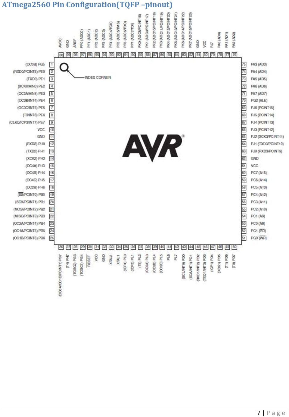
7 ATmega2560 Pin Configuration(TQFP pinout) 7 P a g e

8 ATmega2560 Schematic Block Diagram for the ATmega2560 The ATMega2560 is a low-power CMOS 8-bit microcontroller based on the AVR enhanced RISC architecture. By executing powerful instructions in a single clock cycle, the ATMega2560 achieves throughputs approaching 1 MIPS per MHz allowing the system designer to optimize power consumption versus processing speed. 8 P a g e


9 Breakdown of Rofi parts The table below shows the parts needed to build the Rofi frame. It also shows what parts still need to be printed along with their printed dates. USB Host Shield 2.0 Pin Configuration 9 P a g e

Arduino ADK Back. For information on using the board with the Android OS, see Google's ADK documentation.
 Arduino ADK Arduino ADK R3 Front Arduino ADK R3 Back Arduino ADK Front Arduino ADK Back Overview The Arduino ADK is a microcontroller board based on the ATmega2560 (datasheet). It has a USB host interface
User s Manual of Board Microcontroller ET-MEGA2560-ADK ET-MEGA2560-ADK
 User s Manual of Board Microcontroller ET-MEGA2560-ADK ET-MEGA2560-ADK Because Arduino that is the development project on AVR MCU as Open Source has been published, it is popular and widespread shortly.
http://arduino.cc/en/main/robot?action=print
 Pagina 1 di 7 Arduino : Main / Robot Arduino Robot Robot Top Robot Bottom Overview The Arduino Robot is the first official Arduino on wheels. The robot has two processors, one on each of its two boards.
Arduino Due Back. Warning: Unlike other Arduino boards, the Arduino Due board runs at 3.3V. The maximum. Overview
 R Arduino Due Arduino Due Front Arduino Due Back Overview The Arduino Due is a microcontroller board based on the Atmel SAM3X8E ARM Cortex-M3 CPU (datasheet). It is the first Arduino board based on a 32-bit
8-bit Microcontroller with 64K/128K/256K Bytes In-System Programmable Flash. ATmega640/V ATmega1280/V ATmega1281/V ATmega2560/V ATmega2561/V
 Features High Performance, Low Power Atmel AVR 8-Bit Microcontroller Advanced RISC Architecture 35 Powerful Instructions Most Single Clock Cycle Execution 32 8 General Purpose Working Registers Fully Static
INTRODUCTION TO SERIAL ARM
 INTRODUCTION TO SERIAL ARM A robot manipulator consists of links connected by joints. The links of the manipulator can be considered to form a kinematic chain. The business end of the kinematic chain of
TURBO PROGRAMMER USB, MMC, SIM DEVELOPMENT KIT
 TURBO PROGRAMMER USB, MMC, SIM DEVELOPMENT KIT HARDWARE GUIDE This document is part of Turbo Programmer documentation. For Developer Documentation, Applications and Examples, see http:/// PRELIMINARY (C)
ARDUINO SEVERINO SERIAL SINGLE SIDED VERSION 3 S3v3 (REVISION 2) USER MANUAL
 USER MANUAL") ARDUINO SEVERINO SERIAL SINGLE SIDED VERSION 3 S3v3 (REVISION 2) USER MANUAL X1: DE-9 serial connector Used to connect computer (or other devices) using RS-232 standard. Needs a serial cable, with at least
ARDUINO SEVERINO SERIAL SINGLE SIDED VERSION 3 S3v3 (REVISION 2) USER MANUAL X1: DE-9 serial connector Used to connect computer (or other devices) using RS-232 standard. Needs a serial cable, with at least
ET-BASE AVR ATmega64/128
 ET-BASE AVR ATmega64/128 ET-BASE AVR ATmega64/128 which is a Board Microcontroller AVR family from ATMEL uses MCU No.ATmega64 and ATmega128 64PIN. Board ET-BASE AVR ATmega64/128 uses MCU s resources on
STK500... User Guide
 STK500... User Guide Table of Contents Section 1 Introduction... 1-1 1.1 Starter Kit Features...1-1 1.2 Device Support...1-2 Section 2 Getting Started... 2-1 2.1 Unpacking the System...2-1 2.2 System
Electrical Engineering Department College of Engineering California State University, Long Beach Long Beach, California, 90840
 Electrical Engineering Department College of Engineering California State University, Long Beach Long Beach, California, 90840 EE 400D - Electrical Engineering Design Fall 2012 President: Gary Hill Track
PolyBot Board. User's Guide V1.11 9/20/08
 PolyBot Board User's Guide V1.11 9/20/08 PolyBot Board v1.1 16 pin LCD connector 4-pin SPI port (can be used as digital I/O) 10 Analog inputs +5V GND GND JP_PWR 3-pin logic power jumper (short top 2 pins
8-bit Atmel Microcontroller with 64K/128K/256K Bytes In-System Programmable Flash. ATmega640/V ATmega1280/V ATmega1281/V ATmega2560/V ATmega2561/V
 Features High Performance, Low Power Atmel AVR 8-Bit Microcontroller Advanced RISC Architecture 35 Powerful Instructions Most Single Clock Cycle Execution 32 8 General Purpose Working Registers Fully Static
AVRprog. programmer by MikroElektronika
 USB In System ABOUT PROGRAMMER With complementary software, programmer represents a great tool for all those working with Atmel s AVR. The microcontroller connects to the programmer via 6 lines, two of
Vinco Development Module. Datasheet
 Future Technology Devices International Ltd. Vinco Development Module Datasheet The Vinco module is a Vinculum based development platform inspired by Arduino projects. Document Reference No.: FT_000327
DSO138 oscilloscope program upgrade method
 DSO138 oscilloscope program upgrade method Applicable models: 13801K, 13802K Program upgrade Principle The DSO138 is a SCM STM32F103C8 internal oscilloscope that is preinstalled with a flash bootloader,
Atmel ATmega640/V-1280/V-1281/V-2560/V-2561/V
 Atmel ATmega640/V-1280/V-1281/V-2560/V-2561/V 8-bit Atmel Microcontroller with 16/32/64KB In-System Programmable Flash Features High Performance, Low Power Atmel AVR 8-Bit Microcontroller Advanced RISC
PHYS 2P32 Project: MIDI for Arduino/ 8 Note Keyboard
 PHYS 2P32 Project: MIDI for Arduino/ 8 Note Keyboard University April 13, 2016 About Arduino: The Board Variety of models of Arduino Board (I am using Arduino Uno) Microcontroller constructd similarly
UM1724 User manual. STM32 Nucleo boards. Introduction
 User manual STM32 Nucleo boards Introduction The STM32 Nucleo board (NUCLEO-F030R8, NUCLEO-F072RB, NUCLEO-F103RB, NUCLEO-F302R8, NUCLEO-F334R8, NUCLEO-F401RE, NUCLEO-F411RE, NUCLEO- L053R8, NUCLEO-L152RE)
DATASHEET. ADAM Arduino Display Adaptor Module. Arduino Compatible Shield P/N: 4Display-Shield-FT843 For the 4D Systems 4DLCD-FT843 Display
 DATASHEET ADAM Arduino Display Adaptor Module Arduino Compatible Shield P/N: 4Display-Shield-FT843 For the 4D Systems 4DLCD-FT843 Display Document Date: 8 th January 2014 Document Revision: 1.0 Uncontrolled
Yun Shield User Manual VERSION: 1.0. Yun Shield User Manual 1 / 22. www.dragino.com
 Yun Shield User Manual VERSION: 1.0 Version Description Date 0.1 Initiate 2014-Jun-21 1.0 Release 2014-Jul-08 Yun Shield User Manual 1 / 22 Index: 1 Introduction... 3 1.1 What is Yun Shield... 3 1.2 Specifications...
WIZ-Embedded WebServer User s Manual (Ver. 1.0)
") [텍스트 입력] WIZ-Embedded WebServer User s Manual (Ver. 1.0) 2007 WIZnet Inc. All Rights Reserved. For more information, visit our website at www.wiznet.co.kr Document History Information Revision Data Description
[텍스트 입력] WIZ-Embedded WebServer User s Manual (Ver. 1.0) 2007 WIZnet Inc. All Rights Reserved. For more information, visit our website at www.wiznet.co.kr Document History Information Revision Data Description
AVR Butterfly Training. Atmel Norway, AVR Applications Group
 AVR Butterfly Training Atmel Norway, AVR Applications Group 1 Table of Contents INTRODUCTION...3 GETTING STARTED...4 REQUIRED SOFTWARE AND HARDWARE...4 SETTING UP THE HARDWARE...4 SETTING UP THE SOFTWARE...5
PN532 NFC RFID Module User Guide
 PN532 NFC RFID Module User Guide Version 3 Introduction NFC is a popular technology in recent years. We often heard this word while smart phone company such as Samsung or HTC introduces their latest high-end
Data Sheet. Adaptive Design ltd. Arduino Dual L6470 Stepper Motor Shield V1.0. 20 th November 2012. L6470 Stepper Motor Shield
 Arduino Dual L6470 Stepper Motor Shield Data Sheet Adaptive Design ltd V1.0 20 th November 2012 Adaptive Design ltd. Page 1 General Description The Arduino stepper motor shield is based on L6470 microstepping
AC-PG-USBASP USBASP AVR Programmer
 AC-PG-USBASP-UG TABLE OF CONTENTS 1. OVERVIEW... 1 1.1. Introduction... 1 1.2. References... 1 1.2.1. Referenced Web Pages... 1 1.2.2. Acronyms and Abbreviations... 1 1.3. Supported Microcontrollers...
Embedded Software Development: Spottbillige Hardware + OSS = Zum Spielen zu Schade!
 Embedded Software Development: Spottbillige Hardware + OSS = Zum Spielen zu Schade! Gregor Hohpe www.eaipatterns.com OOP 2012 1 Microcontrollers CPU core, memory, and I/O (analog, digital) on one chip
FLYPORT Wi-Fi 802.11G
 FLYPORT Wi-Fi 802.11G System on module 802.11g WIFI - Infrastructure mode - softap mode - Ad hoc mode Microchip PIC 24F 16 bit processor Microchip MRF24WG0MA/MB - Native WiFi 802.11g transceiver - PCB
EvB 5.1 v5 User s Guide
 EvB 5.1 v5 User s Guide Page 1 Contents Introduction... 4 The EvB 5.1 v5 kit... 5 Power supply...6 Programmer s connector...7 USB Port... 8 RS485 Port...9 LED's...10 Pushbuttons... 11 Potentiometers and
2.0 Command and Data Handling Subsystem
 2.0 Command and Data Handling Subsystem The Command and Data Handling Subsystem is the brain of the whole autonomous CubeSat. The C&DH system consists of an Onboard Computer, OBC, which controls the operation
A 5 Degree Feedback Control Robotic Arm (Haptic Arm)
") A 5 Degree Feedback Control Robotic Arm (Haptic Arm) 1 Prof. Sheetal Nirve, 2 Mr.Abhilash Patil, 3 Mr.Shailesh Patil, 4 Mr.Vishal Raut Abstract: Haptics is the science of applying touch sensation and control
A 5 Degree Feedback Control Robotic Arm (Haptic Arm) 1 Prof. Sheetal Nirve, 2 Mr.Abhilash Patil, 3 Mr.Shailesh Patil, 4 Mr.Vishal Raut Abstract: Haptics is the science of applying touch sensation and control
FTDI Chip. VM800P Datasheet Embedded Video Engine Plus Module. VM800P Embedded Video Engine Plus Module Datasheet Version 1.0
 FTDI Chip VM800P Datasheet Embedded Video Engine Plus Module General Purpose Multi Media Controller The VM800P is a development module for FTDI s FT800, which is used to develop and demonstrate the functionality
HC(S)08-System for Development and Training
08-System for Development and Training") SYSTECH J.Schnyder GmbH Schliefweg 30 CH-4106 Therwil Telefon 091 827 15 87 www.systech.ch HC(S)08-System for Development and Training Overview V 0.3 (Draft English) Contents Components... 3 Hardware...
SYSTECH J.Schnyder GmbH Schliefweg 30 CH-4106 Therwil Telefon 091 827 15 87 www.systech.ch HC(S)08-System for Development and Training Overview V 0.3 (Draft English) Contents Components... 3 Hardware...
Pmod peripheral modules are powered by the host via the interface s power and ground pins.
 Digilent Pmod Interface Specification Revision: November 20, 2011 1300 NE Henley Court, Suite 3 Pullman, WA 99163 (509) 334 6306 Voice (509) 334 6300 Fax Introduction The Digilent Pmod interface is used
Support: http://www.evilmadscientist.com/forum/
 An open-source hardware+software project. For design files and additional documentation, please visit: http://www.evilmadscientist.com/go/diavolino Support: http://www.evilmadscientist.com/forum/ Distributed
Atmel AVR ATxmega384C3 microcontroller OLED display with 128 32 pixels resolution Analog sensors. Ambient light sensor Temperature sensor
 APPLICATION NOTE AVR1925: XMEGA-C3 Xplained Hardware User s Guide Features Atmel AVR ATxmega384C3 microcontroller OLED display with 128 32 pixels resolution Analog sensors Ambient light sensor Temperature
Design and implementation of modular home security system with short messaging system
 EPJ Web of Conferences 68, 00025 (2014) DOI: 10.1051/ epjconf/ 20146800025 C Owned by the authors, published by EDP Sciences, 2014 Design and implementation of modular home security system with short messaging
Web Site: www.parallax.com Forums: forums.parallax.com Sales: sales@parallax.com Technical: support@parallax.com
 Web Site: www.parallax.com Forums: forums.parallax.com Sales: sales@parallax.com Technical: support@parallax.com Office: (916) 624-8333 Fax: (916) 624-8003 Sales: (888) 512-1024 Tech Support: (888) 997-8267
MX PIC24F Educational Module User Manual
 MX PIC24F Educational Module User Manual Revision History Date Description Initial release. Table of Contents 1. Introduction... 3 1.1. Package Contents... 3 1.2. Key Hardware Features... 4 2. Hardware
Introduction. Getting familiar with chipkit Pi
 Overview: chipkit Pi Introduction chipkit Pi (Designed for Raspberry Pi) is the latest Arduino compatible chipkit platform from Microchip and element14. It features a 32 bit PIC32 microcontroller in a
Cypress Semiconductor: Arduino Friendly PSoC Shield
 Cypress Semiconductor: Arduino Friendly PSoC Shield Design Presentation ECE 480 Design Team 1 Cecilia Acosta Brett Donlon Matt Durak Aaron Thompson Nathan Ward Faculty Facilitator Dr. Robert McGough Sponsor
DKWF121 WF121-A 802.11 B/G/N MODULE EVALUATION BOARD
 DKWF121 WF121-A 802.11 B/G/N MODULE EVALUATION BOARD PRELIMINARY DATA SHEET Wednesday, 16 May 2012 Version 0.5 Copyright 2000-2012 Bluegiga Technologies All rights reserved. Bluegiga Technologies assumes
RC2200DK Demonstration Kit User Manual
 Demonstration Kit User Manual Table of contents TABLE OF CONTENTS... 1 QUICK INTRODUCTION... 2 INTRODUCTION... 3 DEMONSTRATION BOARD... 4 POWER SUPPLY SECTION... 5 RS-232 INTERFACE... 6 CONNECTORS... 7
Arduino DUE + DAC MCP4922 (SPI)
") Arduino DUE + DAC MCP4922 (SPI) v101 In this document it will described how to connect and let a Digital/Analog convert work with an Arduino DUE. The big difference between and Arduino DUE and other Arduinos
Arduino DUE + DAC MCP4922 (SPI) v101 In this document it will described how to connect and let a Digital/Analog convert work with an Arduino DUE. The big difference between and Arduino DUE and other Arduinos
KTA-223 Arduino Compatible Relay Controller
 8 Relay Outputs 5A 250VAC 4 Opto-Isolated Inputs 5-30VDC 3 Analog Inputs (10 bit) Connections via Pluggable Screw Terminals 0-5V or 0-20mA Analog Inputs, Jumper Selectable 5A Relay Switching Power Indicator
The Programming Interface
 : In-System Programming Features Program any AVR MCU In-System Reprogram both data Flash and parameter EEPROM memories Eliminate sockets Simple -wire SPI programming interface Introduction In-System programming
Universal EXTension connector (UEXT)
") Universal EXTension connector (UEXT) Revision Initial, September 2011 Copyright(c) 2011, OLIMEX Ltd, All rights reserved Page 1 What is UEXT? Back in year 2000 we start to design different development
Universal EXTension connector (UEXT) Revision Initial, September 2011 Copyright(c) 2011, OLIMEX Ltd, All rights reserved Page 1 What is UEXT? Back in year 2000 we start to design different development
Vibration Measurement of Wireless Sensor Nodes for Structural Health Monitoring
 , pp.18-22 http://dx.doi.org/10.14257/astl.2015.98.05 Vibration Measurement of Wireless Sensor Nodes for Structural Health Monitoring Surgwon Sohn, Seong-Rak Rim, In Jung Lee Div. of Computer and Information
Reconfigurable System-on-Chip Design
 Reconfigurable System-on-Chip Design MITCHELL MYJAK Senior Research Engineer Pacific Northwest National Laboratory PNNL-SA-93202 31 January 2013 1 About Me Biography BSEE, University of Portland, 2002
Cell Phone Operated Land Rover
 Cell Phone Operated Land Rover Sumona Biswas, Bipin Kumar, Aditya kushwaha, Debasish Sardar Department of Electronics and Communication Engineering, Birbhum Institute of Engineering& Technology, Suri(west
Doc: 502-254 page 1 of 17
 chipkit uc32 Board Reference Manual Revision: July 17, 2012 Note: This document applies to REV A of the board. 1300 NE Henley Court, Suite 3 Pullman, WA 99163 (509) 334 6306 Voice (509) 334 6300 Fax Overview
PIC-MAXI-WEB development board Users Manual
 PIC-MAXI-WEB development board Users Manual Rev.A, July 2008 Copyright(c) 2008, OLIMEX Ltd, All rights reserved INTRODUCTION: This board allows you to easily develop Ethernet connectivity applications.
Lab Experiment 1: The LPC 2148 Education Board
 Lab Experiment 1: The LPC 2148 Education Board 1 Introduction The aim of this course ECE 425L is to help you understand and utilize the functionalities of ARM7TDMI LPC2148 microcontroller. To do that,
WICE-SPI Hardware Operation Manual
 Contents 1.Hardware Instruction...1 2. Pin Definition Of WICE-SPI Connector...2 3. Peripheral Circuit Arrangements...3 4. On-Board Programming...4 5. Off-Line Programming...8 1.Hardware Instruction 1.WICE-SPI
AT15007: Differences between ATmega328/P and ATmega328PB. Introduction. Features. Atmel AVR 8-bit Microcontrollers APPLICATION NOTE
 Atmel AVR 8-bit Microcontrollers AT15007: Differences between ATmega328/P and ATmega328PB APPLICATION NOTE Introduction This application note assists the users of Atmel ATmega328 variants to understand
PCAN-MicroMod Evaluation Test and Development Environment for the PCAN-MicroMod. User Manual. Document version 2.0.1 (2013-08-06)
") PCAN-MicroMod Evaluation Test and Development Environment for the PCAN-MicroMod User Manual Document version.0. (0-0-0) Products taken into account Product Name Part number Model PCAN-MicroMod Evaluation
PCAN-MicroMod Evaluation Test and Development Environment for the PCAN-MicroMod User Manual Document version.0. (0-0-0) Products taken into account Product Name Part number Model PCAN-MicroMod Evaluation
Serial port interface for microcontroller embedded into integrated power meter
 Serial port interface for microcontroller embedded into integrated power meter Mr. Borisav Jovanović, Prof. dr. Predrag Petković, Prof. dr. Milunka Damnjanović, Faculty of Electronic Engineering Nis, Serbia
Block 3 Size 0 KB 0 KB 16KB 32KB. Start Address N/A N/A F4000H F0000H. Start Address FA000H F8000H F8000H F8000H. Block 2 Size 8KB 16KB 16KB 16KB
 APPLICATION NOTE M16C/26 1.0 Abstract The following article describes using a synchronous serial port and the FoUSB (Flash-over-USB ) Programmer application to program the user flash memory of the M16C/26
ALL-USB-RS422/485. User Manual. USB to Serial Converter RS422/485. ALLNET GmbH Computersysteme 2015 - Alle Rechte vorbehalten
 ALL-USB-RS422/485 USB to Serial Converter RS422/485 User Manual ALL-USB-RS422/485 USB to RS-422/485 Plugin Adapter This mini ALL-USB-RS422/485 is a surge and static protected USB to RS-422/485 Plugin Adapter.
Electronic Interface for Pneumatic Grippers Using USB Port
 ISBN 978-1-84626-xxx-x Proceedings of 2011 International Conference on Optimization of the Robots and Manipulators (OPTIROB 2011) Sinaia, Romania, 26-28 Mai, 2011, pp. xxx-xxx Electronic Interface for
Part 1. MAX 525 12BIT DAC with an Arduino Board. MIDI to Voltage Converter Part1
 MIDI to Voltage Converter Part 1 MAX 525 12BIT DAC with an Arduino Board 1 What you need: 2 What you need : Arduino Board (Arduino Mega 2560) 3 What you need : Arduino Board (Arduino Mega 2560) Digital
SM1231 USER GUIDE SM1231 RF MODULE USER GUIDE
 SM1231 RF MODULE Revision 1.0 11/2009 Page 1 of 8 www.semtech.com Table of Contents Table of Contents...2 Index of Figures...2 Index of Tables...2 1 Introduction...3 2 Reference Design...3 3 PCB Layout...6
Board also Supports MicroBridge
 This product is ATmega2560 based Freeduino-Mega with USB Host Interface to Communicate with Android Powered Devices* like Android Phone or Tab using Android Open Accessory API and Development Kit (ADK)
Development of an Internet based Embedded System for Smart House Controlling and Monitoring
 Development of an Internet based Embedded System for Smart House Controlling and Monitoring Ahmed Abd-Elkarim Abd- Ellatif Salih Maged Ali Mohammed Asa'ad Yousif Elhadi Elsideeg Ahmed Department of Computer
8-bit Atmel megaavr Microcontroller
 8-bit Atmel megaavr Microcontroller ATmega16M1 / ATmega32M1 / ATmega64M1 Summary Features High performance, low power Atmel AVR 8-bit microcontroller Advanced RISC architecture 131 powerful instructions
CMOS OV7660 Camera Module 1/5-Inch 0.3-Megapixel Module Datasheet
 CMOS OV7660 Camera Module 1/5-Inch 0.3-Megapixel Module Datasheet Rev 1.0, June 2013 Table of Contents 1 Introduction...2 2 Features...3 3 Key Specifications...4 4 Application...4 5 Pin Definition...6
[F/T] [5] [KHz] [AMP] [3] [V] 4 ) To set DC offset to -2.5V press the following keys [OFS] [+/-] [2] [.] [5] [V]
![[F/T] [5] [KHz] [AMP] [3] [V] 4 ) To set DC offset to -2.5V press the following keys [OFS] [+/-] [2] [.] [5] [V]](/thumbs/40/20623504.jpg "[F/T] [5] [KHz] [AMP] [3] [V] 4 ) To set DC offset to -2.5V press the following keys [OFS] [+/-] [2] [.] [5] [V]") FG085 minidds Function Generator Manual of Operation Applicable Models: 08501, 08501K, 08502K, 08503, 08503K Applicable Firmware Version: 1 ) 113-08501-100 or later (for U5) 2 ) 113-08502-030 or later
FG085 minidds Function Generator Manual of Operation Applicable Models: 08501, 08501K, 08502K, 08503, 08503K Applicable Firmware Version: 1 ) 113-08501-100 or later (for U5) 2 ) 113-08502-030 or later
Project Plan. Project Plan. May13-06. Logging DC Wattmeter. Team Member: Advisor : Ailing Mei. Collin Christy. Andrew Kom. Client: Chongli Cai
 Project Plan May13-06 Logging DC Wattmeter Team Member: Ailing Mei Andrew Kom Chongli Cai Advisor : Collin Christy Client: Garmin International David Hoffman Qiaoya Cui Table of Contents Need Statement...
ATmega128A. Introduction. Features. 8-bit AVR Microcontroller DATASHEET COMPLETE
 8-bit AVR Microcontroller ATmega128A DATASHEET COMPLETE Introduction The Atmel ATmega128A is a low-power CMOS 8-bit microcontroller based on the AVR enhanced RISC architecture. By executing powerful instructions
FRDM-KL25Z User's Manual 2012-09-24 Rev. 1.0
 FRDM-KL25Z User's Manual 2012-09-24 Rev. 1.0 Freescale Semiconductor, Inc. FRDMKL25ZUM Table of Contents 1 Overview... 3 2 Reference Documents... 3 3 Getting Started... 3 4 FRDM-KL25Z Hardware Overview...
SAM D21 Xplained Pro. Preface. SMART ARM-based Microcontrollers USER GUIDE
 SMART ARM-based Microcontrollers SAM D21 Xplained Pro USER GUIDE Preface The Atmel SAM D21 Xplained Pro evaluation kit is a hardware platform to evaluate the ATSAMD21J18A microcontroller. Supported by
SMARTCARD XPRO. Preface. SMART ARM-based Microcontrollers USER GUIDE
 SMART ARM-based Microcontrollers SMARTCARD XPRO USER GUIDE Preface Atmel SMARTCARD Xplained Pro is an extension board to the Atmel Xplained Pro evaluation platform. Atmel SMARTCARD Xplained Pro is designed
ADVANCED FIRE ALARMING SYSTEM THROUGH MOBILE PHONE
 ADVANCED FIRE ALARMING SYSTEM THROUGH MOBILE PHONE A PROJECT BY SOUNAK SARKAR SAYAN DAS ARINDAM BOSE ECE, 4TH YEAR OF FUTURE INSTITUTE OF ENGINEERING AND MANAGEMENT DEPT. OF ELECTRONICS AND COMMUNICATION
Quick Start Guide. TWR-MECH Mechatronics Board TOWER SYSTEM
 TWR-MECH Mechatronics Board TOWER SYSTEM Get to Know the Tower Mechatronics Board Primary Connector / Switch MCF52259 Connectors for Up to Eight Servos SW4 (Reset) USB OTG 5V Supply Touch Panel Socket
System theremino MasterDIL-V3
 System theremino MasterDIL-V3 System theremino - MasterDIL-V3 - Datasheet - March 8, 2013 - Page 1 The Master module The "Master" is the main module of the system Theremino. It puts in communication the
Palaparthi.Jagadeesh Chand. Associate Professor in ECE Department, Nimra Institute of Science & Technology, Vijayawada, A.P.
 Patient Monitoring Using Embedded Palaparthi.Jagadeesh Chand Associate Professor in ECE Department, Nimra Institute of Science & Technology, Vijayawada, A.P Abstract The aim of this project is to inform
Bluetooth + USB 16 Servo Controller [RKI-1005 & RKI-1205]
![Bluetooth + USB 16 Servo Controller [RKI-1005 & RKI-1205]](/thumbs/40/21161302.jpg "Bluetooth + USB 16 Servo Controller [RKI-1005 & RKI-1205]") Bluetooth + USB 16 Servo Controller [RKI-1005 & RKI-1205] Users Manual Robokits India info@robokits.co.in http://www.robokitsworld.com Page 1 Bluetooth + USB 16 Servo Controller is used to control up to
Bluetooth + USB 16 Servo Controller [RKI-1005 & RKI-1205] Users Manual Robokits India info@robokits.co.in http://www.robokitsworld.com Page 1 Bluetooth + USB 16 Servo Controller is used to control up to
Using the HT46R46 I/O Ports to Implement Half-Duplex SPI Communication
 Using the HT46R46 I/O Ports to Implement Half-Duplex SPI Communication D/N: HA0150E Introduction This application explains how to use two I/O lines on the HT46R46 to implement half-duplex SPI communication.
Hand Gestures Remote Controlled Robotic Arm
 Advance in Electronic and Electric Engineering. ISSN 2231-1297, Volume 3, Number 5 (2013), pp. 601-606 Research India Publications http://www.ripublication.com/aeee.htm Hand Gestures Remote Controlled
Green House Monitoring and Controlling Using Android Mobile Application
 Green House Monitoring and Controlling Using Android Mobile Application Aji Hanggoro aji.hanggoro@ui.ac.id Mahesa Adhitya Putra mahesa.adhitya91@ui.ac.id Rizki Reynaldo rizki.reynaldo@ui.ac.id Riri Fitri
www.dragino.com Yun Shield Quick Start Guide VERSION: 1.0 Version Description Date 1.0 Release 2014-Jul-08 Yun Shield Quick Start Guide 1 / 14
 Yun Shield Quick Start Guide VERSION: 1.0 Version Description Date 1.0 Release 2014-Jul-08 Yun Shield Quick Start Guide 1 / 14 Index: 1 Introduction... 3 1.1 About this quick start guide... 3 1.2 What
Tutorial for MPLAB Starter Kit for PIC18F
 Tutorial for MPLAB Starter Kit for PIC18F 2006 Microchip Technology Incorporated. All Rights Reserved. WebSeminar Title Slide 1 Welcome to the tutorial for the MPLAB Starter Kit for PIC18F. My name is
PICNet 1. PICNet 1 PIC18 Network & SD/MMC Development Board. Features. Applications. Description
 Features PICNet 1 PIC18 Network & SD/MMC Development Board IC Sockets for 28 or 40-pin Microchip PIC18F Microcontrollers IC Socket for 8-pin serial EEPROM Multiple MCU Oscillator sources Full 10BaseT IEEE
DATA LOGGER AND REMOTE MONITORING SYSTEM FOR MULTIPLE PARAMETER MEASUREMENT APPLICATIONS. G.S. Nhivekar, R.R.Mudholker
 e -Journal of Science & Technology (e-jst) e-περιοδικό Επιστήμης & Τεχνολογίας 55 DATA LOGGER AND REMOTE MONITORING SYSTEM FOR MULTIPLE PARAMETER MEASUREMENT APPLICATIONS G.S. Nhivekar, R.R.Mudholker Department
PROGRAMMABLE WIRELESS STAMP (PWS) USER MANUAL
 USER MANUAL") TABLE OF CONTENTS Overview... 2 High Level Features... 6 Operating Parameters... 7 Pinout and Terminal Descriptions... 8 Physical Dimensions... 9 Recommended Operating Conditions... 10 Battery Charger
TABLE OF CONTENTS Overview... 2 High Level Features... 6 Operating Parameters... 7 Pinout and Terminal Descriptions... 8 Physical Dimensions... 9 Recommended Operating Conditions... 10 Battery Charger
ARM Cortex -A8 SBC with MIPI CSI Camera and Spartan -6 FPGA SBC1654
 ARM Cortex -A8 SBC with MIPI CSI Camera and Spartan -6 FPGA SBC1654 Features ARM Cortex-A8 processor, 800MHz Xilinx Spartan-6 FPGA expands vision processing capabilities Dual MIPI CSI-2 CMOS camera ports,
Wireless Security Camera
 Wireless Security Camera Technical Manual 12/14/2001 Table of Contents Page 1.Overview 3 2. Camera Side 4 1.Camera 5 2. Motion Sensor 5 3. PIC 5 4. Transmitter 5 5. Power 6 3. Computer Side 7 1.Receiver
PCAN-MicroMod Universal I/O Module with CAN Interface. User Manual. Document version 2.1.0 (2014-01-16)
") PCAN-MicroMod Universal I/O Module with CAN Interface User Manual Document version 2.1.0 (2014-01-16) Products taken into account Product Name Part number Model PCAN-MicroMod IPEH-002080 with firmware
PCAN-MicroMod Universal I/O Module with CAN Interface User Manual Document version 2.1.0 (2014-01-16) Products taken into account Product Name Part number Model PCAN-MicroMod IPEH-002080 with firmware
CP2110-EK CP2110 EVALUATION KIT USER S GUIDE. 1. Kit Contents. 2. Relevant Documentation. 3. Software Setup
 CP2110 EVALUATION KIT USER S GUIDE 1. Kit Contents The CP2110 Evaluation Kit contains the following items: CP2110 Evaluation Board RS232 Serial Cable USB Cable DVD Quick Start Guide 2. Relevant Documentation
VF2F. USB Flash Disk File-to-file Transfer Vinculum Evaluation Kit. Future Technology Devices International Ltd. Preliminary - Subject to Change
 Future Technology Devices International Ltd. VF2F USB Flash Disk File-to-file Transfer Vinculum Evaluation Kit http://www.vinculum.com Copyright Future Technology Devices International Ltd. 2006 1. Introduction
RZ/T1 Group. User's Manual. Renesas Starter Kit+ User s Manual For e 2 studio. RENESAS MCU Family / RZ/T1 Series. Rev. 1.
 User's Manual 32 RZ/T1 Group Renesas Starter Kit+ User s Manual For e 2 studio RENESAS MCU Family / RZ/T1 Series All information contained in these materials, including products and product specifications,
MARTECH SPI Tools. MARTECH SPI Tools User Manual v1.0. User Manual
 MARTECH SPI Tools v1.0 Contents 1. Basic informations about the product...3 1.1 Memory types supported by SPI Tool...3 2. Main features and application possibilities...4 2.1 Technical Support activation...4
Atmel AT32UC3A3256 microcontroller 64MBit SDRAM Analog input (to ADC) Temperature sensor RC filter
 Temperature sensor RC filter") APPLICATION NOTE Features Atmel AVR32918: UC3-A3 Xplained Hardware User s Guide Atmel AT32UC3A3256 microcontroller 64MBit SDRAM Analog input (to ADC) Temperature sensor RC filter I/O One mechanical button
APPLICATION NOTE Features Atmel AVR32918: UC3-A3 Xplained Hardware User s Guide Atmel AT32UC3A3256 microcontroller 64MBit SDRAM Analog input (to ADC) Temperature sensor RC filter I/O One mechanical button
SAM G55 Xplained Pro. Preface. SMART ARM-based Microcontrollers USER GUIDE
 SMART ARM-based Microcontrollers SAM G55 Xplained Pro USER GUIDE Preface The Atmel SAM G55 Xplained Pro evaluation kit is a hardware platform to evaluate the ATSAMG55J19 microcontroller. This kit is supported
BE635 User Manual. Rev. V1.0. 2013-2014 Bolymin, Inc. All Rights Reserved.
 BE635 User Manual Rev. V1.0 2013-2014 Bolymin, Inc. All Rights Reserved. Copyright Copyright 2013-2014 BOLYMIN, INC. All rights reserved. No part of the materials may be reproduced, copied or translated
MFRD52x. Mifare Contactless Smart Card Reader Reference Design. Document information
 Rev. 2.1 17. April 2007 Preliminary Data Sheet Document information Info Keywords Content MFRC522, MFRC523, MFRC52x, MFRD522, MFRD523, Mifare Contactless Smart Card Reader Reference Design, Mifare Reader
Design Considerations in Adding USB Communications to Embedded Applications
 Design Considerations in Adding USB Communications to Embedded Applications Designing universal serial bus (USB) communications into an application enables a system to communicate with a variety of USB
AUTOMATIC NIGHT LAMP WITH MORNING ALARM USING MICROPROCESSOR
 AUTOMATIC NIGHT LAMP WITH MORNING ALARM USING MICROPROCESSOR INTRODUCTION This Project "Automatic Night Lamp with Morning Alarm" was developed using Microprocessor. It is the Heart of the system. The sensors
Microcontroller Based Low Cost Portable PC Mouse and Keyboard Tester
 Leonardo Journal of Sciences ISSN 1583-0233 Issue 20, January-June 2012 p. 31-36 Microcontroller Based Low Cost Portable PC Mouse and Keyboard Tester Ganesh Sunil NHIVEKAR *, and Ravidra Ramchandra MUDHOLKAR
Open Architecture Design for GPS Applications Yves Théroux, BAE Systems Canada
 Open Architecture Design for GPS Applications Yves Théroux, BAE Systems Canada BIOGRAPHY Yves Théroux, a Project Engineer with BAE Systems Canada (BSC) has eight years of experience in the design, qualification,