Line Loss WSDOT Winter 2008 BZA
|
|
|
- Lynette Wilcox
- 10 years ago
- Views:
Transcription
1 Electrical Design Training Class Line Loss WSDOT Winter 2008 BZA Presented by: Keith Calais 1

2 OHM S LAW P = Watts (Power) I = CURRENT (AMPERES) R = RESISTANCE (OHMS) E = ELECTROMOTIVE FORCE (VOLTS) P = EI WATTS = AMPERES X VOLTS I = E R AMPERES = VOLTS OHMS R = E I OHMS = VOLTS AMPERES E = IR VOLTS = AMPERES X OHMS 2

3 3
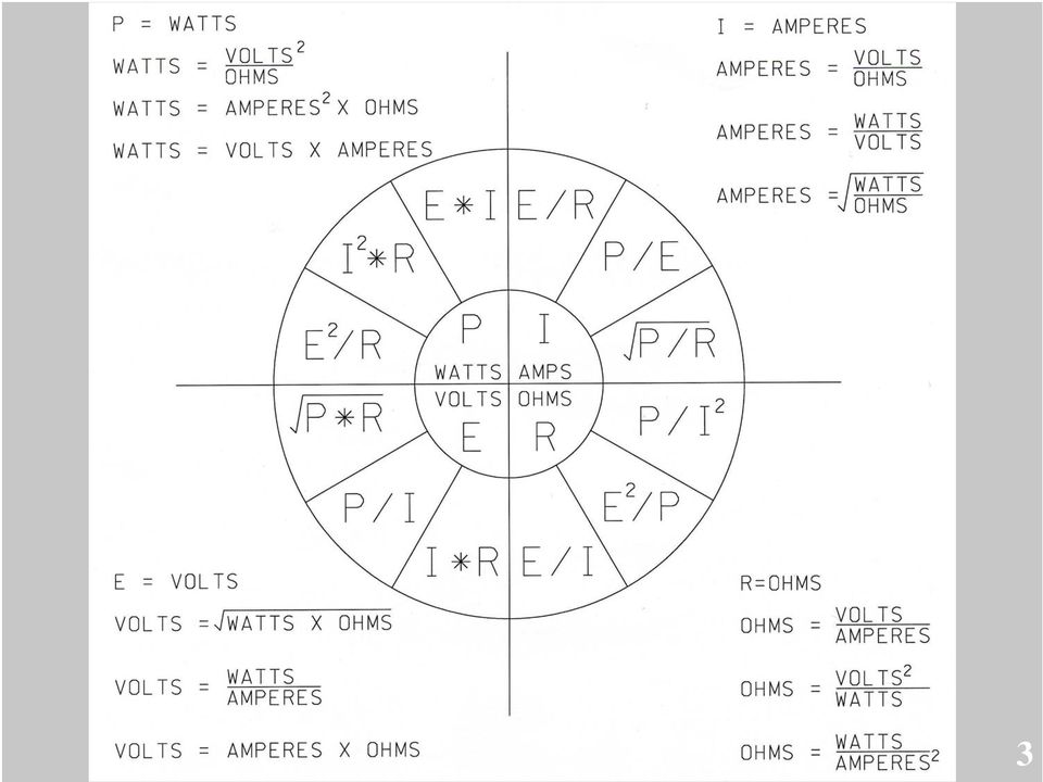
4 Clear Catinkus for PIER (Power) ( P ) Power is the amount of current times the voltage level at a given point measured in wattage or watts. (I ) Current is what flows on a wire or conductor like water flowing down a stream. Current flows from points of high voltage to points of low voltage on the surface of a conductor. Current is measured in (A) amperes or amps. ( E ) Voltage is the difference in electrical potential between two points in a circuit. It's the pressure or push behind current flow through a circuit, and is measured in (V) volts. ( R ) Resistance determines how much current will flow through a component. Resistors are used to control voltage and current levels. A very high resistance allows a small amount of current to flow. A very low resistance allows a large amount of current to flow. Resistance is measured in ohms. 4
 volts. ( R ) Resistance determines how much current will flow through a component.")
5 Example A circuit having a resistance of 5 ohms is under a pressure of 110 volts. How much current will flow? amperes = volts / resistance amperes = 110 volts / 5 ohms answer = 22 amperes 5

6 Example If the resistance of a circuit is 10 ohms, what is the voltage necessary for a flow of 20 amperes? volts = amperes x ohms volts = 20 amperes x 10 ohms Answer = 200 volts 6

7 Example On a 110 volt circuit what resistance is necessary to obtain a flow of 15 amperes? ohms = volts / amperes ohms = 110 volts / 15 amperes Answer = 7.33 ohms 7

8 Example A water heater is served by a 240 volt circuit. The heating element is 4500 watts. What is the load on this circuit? 4500 watt heating element / 240 volts = amps On this circuit, what resistance is necessary within the heating element to obtain the flow of amperes? ohms = volts / amperes ohms = 240 volts / amperes Answer = ohms 8

9 Example A coffee pot is served by a 120 volt circuit. The heating element is 1500 watts. What is the load on this circuit? 1500 watt heating element / 120 volts = amps On this circuit, what resistance is necessary within the heating element to obtain the flow of amperes? ohms = volts / amperes ohms = 120 volts / amperes Answer = 9.60 ohms 9

10 Electrical Energy Unit Conversions 1 watt = 1 volt x 1 ampere x power factor* * * watts = volt amperes 1 ampere = 1 watt / 1 volt 1 volt = 1 watt / 1 ampere k = 1000 (accepted convention that k indicates 1000) NEC 110.6, Conductor sizes - comments watts / 1000 = kilo volt ampere (kva) 1,528 watts / 1000 = kva kva x 1000 = watts (or volt amperes) kva x 1000 = 3,224 watts (or volt amperes) * * * For WSDOT calculation purposes the power factor is assumed to be 1. 10
 3.")
11 #3/0 #2 #1/0 #6 #10 #14 #4 #8 #12 #10-Pole and Bracket Cable 11

12 What is Line Loss? Line Loss is the voltage drop (Vd) between the electrical service and the load. Line loss usually controls wire size determination rather than the allowable ampacities listed in Chapter 3 of the National Electrical Code. Recommended allowable voltage drop is discussed in 2005 NEC article , FPN No.4 12

13 Why do we need to worry about Voltage Drop? If you have too much Voltage Drop on a circuit, the equipment you are trying to power may not work. Inefficiency equals using more power and receiving less output. (see reasonable operating efficiency commentary after NEC 2005 Article in the handbook) You need to make sure you have enough capacity for future use. (Figure 3-4% for future Illumination loads and 1-2% for future ITS loads.) 13

14 Maximum Voltage Drop Requirements High Pressure Sodium - ultimate loads known Vd = 8%, unknown Vd = 5%. Metal Halide - ultimate loads known Vd = 8%, unknown Vd = 5%. Mercury Vapor - ultimate loads known Vd = 10%, unknown Vd = 5%. Temporary Illumination System (installed & removed within same contract) - Vd = 10%. Traffic Signal -Vd = 5%. ITS System - Vd = 3% 14
 - Vd = 10%.")
15 Wire size On new ITS circuits that are not powered by a transformer, pick your wire size so that you have 1.5-2% voltage drop. On transformers that have GFCI s included in the loading calculations, pick your wire so that you have 5% maximum voltage drop. If there are no GFCI s included (load for pump, fan motors, etc.) then use 3% voltage drop. Note: All transformers referred to in this class are for ITS or Traffic Signal loads. To size a transformer for a pump, motor or other specialty item, consult HQ Traffic Design. On new illumination circuits (ultimate load unknown) pick your wire size so that you have 4-5% voltage drop. On new signal circuits pick your wire size so that you have 3-4% voltage drop. On existing ITS circuits where you are replacing the wire the maximum voltage drop allowed is 3%. On existing signal circuits where you are replacing the wire the maximum voltage drop allowed is 5%. On existing illumination circuits (ultimate load known) where you are replacing the wire the maximum voltage drop allowed is 8%. 15
 pick your wire size so that you have 4-5% voltage drop.")
16 How do we calculate Voltage Drop? In order to calculate line loss you need to know: This formula: Vd = 2ALR Where: Vd= Voltage Drop. 2 = because the power goes out and back using two wires. A = load being drawn. (Amperes) L = distance the load is being carried. (Feet one way length of the circuit) R = resistance per foot of wire used. (Ohms) When looking up the R factor in the chart you need to know two things: The wire size carrying the load. (#2, #4, #6, #8, etc.) The type of wire being used. (Copper or Aluminum) 16
 R = resistance per foot of wire used.")
17 Determining the R Use these columns depending on wire type Size X-Section (copper only) Copper Aluminum (AWG) (Square Inches) (Amps) (ohms/foot) (ohms/foot) 500 Kcmil Kcmil Kcmil / / / / * * * degree Celcius insulation NEC, Chapter 9, Table 5-Type RHW* conductors-w/o outer covering NEC, Table *reduced per Article 240.4(D) NEC Chapter 9, Table 8 NEC Chapter 9, Table

18 Calculating the distance (L) between loads Scale off the distance between each load or the distance between the load and the service. Add 5 when entering the service cabinet or another cabinet to power. Add 10 per in-grade junction box that the wire passes through. This takes into account the conduit sweeps and the 3 of slack wire. Add 5 to each side of wire run (instead of 10 ) when there is a splice in the junction box. Add 5 for the sweep into the luminaire and up to the handhole. Add 5 for NEMA junction boxes. Add 2 to each side of wire run (instead of 5 ) when there is a splice in the NEMA junction box. Add 52 (for 40 pole with 16 mast arm) or 62 (for 50 pole with 16 mast arm) to the distance to accommodate for the last luminaire pole and mast arm on each run. Use a #10 wire (pole & bracket cable) for this distance. Add 2 to enter terminal cabinet and terminate conductor on terminal block. For aerial temporary illumination, add 10% of the total span length of aerial conductors. 18
 when there is a splice in the NEMA junction box.")
19 Different Types of Loads (A) There are three different types of loads that we calculate. 1.) Intelligent Transportation System (ITS), (previously SC&DI) 2.) Traffic Signal System 3.) Illumination System (including sign lights) There are different ways to calculate each of these loads 19
 Traffic Signal System 3.")
20 Amps - voltage relationship - Example The basic way a load is calculated is by dividing the wattage (Volt Amperes) by the voltage serving the load. 2520W(or 2.52kVA) 120V 2520W(or 2.52kVA) 240V 2520W(or 2.52kVA) 480V = 21.0Amps = 10.5Amps = 5.25Amps 7500W(or 7.5kVA) 120V 7500W(or 7.5kVA) 240V 7500W(or 7.5kVA) 480V =62.5Amps =31.25Amps =15.625Amps 20
 120V 7500W(or 7.5kVA) 240V 7500W(or 7.5kVA) 480V =62.5Amps =31.")
21 ITS Loads An ITS circuit is sized for the ultimate load that can be drawn at one time. This is usually controlled by the rated output of the transformer. If there is no transformer, use the figures below to calculate your loads. Most ITS cabinet are served with a 120 volt circuit this is why you typically serve these cabinets with a transformer. Check your cabinet voltage requirement if you don t know. Ramp Meter (RM) -720W+1800W(GFCI s)=2520w Camera Cabinet (CC) -324W+1800W(GFCI s)=2124w Data Station (ES) -252W+1800W(GFCI s)=2052w Highway Advisory Radio Station (HAR)-200W+1800W(GFCI s)=2000w RWIS 120W+1800W(GFCI s)=1920w Permanent Traffic Recorder & Weigh-In-Motion-240W W(GFCI s)= 2040W Variable Message Sign (VMS)-Contact the ITS designer because each sign requires a different loading. If you are the ITS designer contact the manufacturers for like size and type VMS Sign data. (Generally, if the load is below 1800 watts, there is not an included GFCI load.) If the load is larger than 1800 watts, then a GFCI load is assumed to be included. Consult with ITS designers to let them know this is your intention and to make sure this will be adequate. If you are the ITS designer, please keep this in mind.) 21
22 ITS - Example The basic way a load is calculated is by dividing the wattage (Volt Amperes) by the voltage serving the load. 2520W(or 2.52kVA) 120V = 21.0Amps 7500W(or 7.5kVA) 240V 7500W(or 7.5kVA) 480V = 31.25Amps =15.625Amps 22
23 Signal Loads - LED A Signal circuit is sized for the ultimate load that can be drawn at one time. This is usually the sum of the items below: 300W Controller 1800W GFCI s (receptacles - vent fan & cabinet light(s) are included within this load) 15W multiply by the Total # of Pedestrian Displays 25W for 12 heads (signal displays) or 15W for 8 heads (flashing beacon displays)-multiply by the Total # of Vehicle Display Lamps illuminated at one time (1 Lamp per 3 section display, 2 Lamps per 4 or 5 section display) USE THESE NUMBERS FOR SIZING CONDUCTORS. 23
24 Signal Loads LED - Example For a T intersection use 9-vehicle heads, and 6-pedestrian heads. 300W+1800W+(9*25W)+(6*15W)=2415W 2415W 120V =20.125Amps For a four legged intersection use 12-vehicle heads, and 8-pedestrian heads. 300W+1800W+(12*25W)+(8*15W)=2520W 2520W 120V =21.00Amps If there are supplemental heads used in your design these values may be larger. Use these values as a minimum. 24
25 Signal Loads - incandescent A Signal circuit is sized for the ultimate load that can be drawn at one time. This is usually the sum of the items below: 300W Controller 1800W GFCI s (receptacles - vent fan & cabinet light(s) are included within this load) 116W multiply by the Total # of Pedestrian Displays 165W for 12 heads (signal displays) or 69W for 8 heads (flashing beacon displays)-multiply by the Total # of Vehicle Display Lamps illuminated at one time (1 Lamp per 3 section display, 2 Lamps per 4 or 5 section display) USE THE LED NUMBERS FOR SIZING CONDUCTORS. 25
26 Signal Loads - incandescent - Example For a T intersection use 9-vehicle heads, and 6-pedestrian heads. 300W+1800W+(9*165W)+(6*116W)=4281W 4281W 120V =35.675Amps For a four legged intersection use 12-vehicle heads, and 8-pedestrian heads. 300W+1800W+(12*165W)+(8*116W)=5008W 5008W 120V =41.73Amps If there are supplemental heads used in your design these values may be larger. Use these values as a minimum. 26
27 8 Lens incandescent 1 lamp = 69 watts 2 lamps = 138 watts 4 lamps = 276 watts 8 Lens LED 1 lamp = 15 watts 2 lamps = 30 watts 4 lamps = 60 watts Flashing Beacons 12 Lens incandescent 1 lamp = 165 watts 2 lamps = 330 watts 4 lamps = 660 watts 12 Lens LED 1 lamp = 25 watts 2 lamps = 50 watts 4 lamps = 100 watts The dimmable flashing unit draws amps at 120 volts. For line loss calculation purposes, you can ignore the dimming flasher unit load. A large majority of existing flashers have 1 or 2 eight inch lens. The need would have to be great before you would use twelve inch lens. 27
28 Illumination Loads Each luminaire has a different lamp load factor depending on what wattage lamp and what voltage you are using. You have to check the manufacturers catalog cuts to see what voltage the particular luminaire draws during it s start-up period. This is roughly the same as multiplying the wattage by 1.2 then dividing by the serving voltage, but the catalog values are more accurate. These are the numbers from the GE catalog. HPS HPS MH MH Bulb AMPS Load@ AMPS Load@ AMPS Load@ AMPS Load@ Wattage 240V 480V 240V 480V * * Mercury Vapor 28
29 Illumination Load Examples 175W MV = ~ 240w / 480v = 0.5 Amps 250w HPS = ~ 336w / 480v = 0.7Amps 310w HPS = ~ 432w / 480v = 0.9Amps 400w HPS = ~ 528w / 480v = 1.1Amps 29
30 Things to consider when laying out your circuits Try to balance the loads on your circuits. Run an individual branch circuit to each cabinet. No illumination circuit breaker can be larger than 50 amps. (NEC D) Distance vs load running large wire a long distance it may be better to install a new service. Example: 1000 of #2 wire inside 2 conduit = $26,860. New Type B, 25 feet of conduit & #8 conductors +$6,000 (plus utility hookup fee). Stagger lights on different circuits on a roadway: Order of preference: Every other light on a roadway is on a different circuit. Each side of roadway is on a different circuit. Each leg of an intersection is on a different circuit. Everything is on one circuit. 30
31 31 31
32 32 32
33 33 33
34 34 34
35 35 35
36 36 36
37 37 37
38 Circuit A Load calculations Illumination Circuit A load watt, HPS Luminaires, 480 VAC, 0.7 Amps per luminaire 12 x 0.7 amps = 8.4 Amps 38
39 Total load on Segment Wire out and Back Voltage Drop for Circuit A, Leg #1 1st try Vd=2ALR Total length of Segment Resistance of #8 conductor Service to M=2(8.4)(5cab+15+5(1/2jb)=25)( ) = M to H =2(5.6)(10(1jb)+170=180)( ) = H to G =2(2.8)(20(2jb) (3n)=495)( ) = G to F =2(2.1)(70(7jb)+1225 =1295)( ) = F to C =2(1.4)(10(1jb)+165 =175)( ) = C to E =2(0.7)(70(7jb) (1/2jb)+5(ls) =1470)( )= Hand hole to Light =2(0.7)(52)( ) = /480= *100=2.2% Vd 2.2% < 5% - #8 wire is acceptable Resistance of #8 conductor Resistance of #10 conductor 39
40 40 40
41 Total load on Segment Wire out and Back Voltage Drop for Circuit A, Leg #2 1st try Vd=2ALR Total length of Segment Resistance of #8 conductor Service to M=2(8.4)(5cab+15+5(1/2jb)=25)( ) = M to H =2(5.6)(10(1jb)+170=180)( ) = H to G =2(2.8)(20(2jb) (3n)=495)( ) = G to F =2(2.1)(70(7jb)+1225 =1295)( ) = F to C =2(1.4)(10(1jb)+165 =175)( ) = C to B =2(0.7)(45(4.5jb)+720+5(ls)=770)( ) = Hand hole to Light =2(0.7)(52)( ) = /480= *100=2.1% Vd 2.1% < 5% - #8 wire is acceptable Resistance of #8 conductor Resistance of #10 conductor 41
42 42 42
43 Total load on Segment Wire out and Back Voltage Drop for Circuit A, Leg #3 1st try Vd=2ALR Total length of Segment Resistance of #8 conductor Service to M=2(8.4)(5cab+15+5(1/2jb)=25)( ) = M to H =2(5.6)(10(1jb)+170=180)( ) = H to L =2(2.1)(20(2jb)+375 =395)( ) = L to K =2(1.4)(20(2jb)+270 =290)( ) = K to J =2(0.7)(25(2.5jb)+335+5(1n)+5(ls) =370)( ) = Hand hole to Light =2(0.7)(52)( ) = /480= *100=0.93% Vd 0.93% < 5% - #8 wire is acceptable Resistance of #8 conductor Resistance of #10 conductor 43
44 44 44
45 Total load on Segment Wire out and Back Voltage Drop for Circuit A, Leg #4 1st try Vd=2ALR Total length of Segment Resistance of #8 conductor Service to M=2(8.4)(5cab+15+5(1/2jb)=25)( ) = M to N =2(2.1)(40(4jb) (2n)=775)( ) = N to O =2(1.4)(50(5jb)+940=990)( ) = O to P =2(0.7)(60(6jb) (1/2jb)+5(ls)=1235)( )= Hand hole to Light =2(0.7)(52)( ) = /480= *100=1.40% Vd 1.40% < 5% - #8 wire is acceptable Resistance of #8 conductor Resistance of #10 conductor 45
46 46 46
47 47
48 48
49 49
50 50
51 51
52 52
53 53
54 Circuit D Load calculations Illumination Circuit D load watt, HPS Luminaires, 480 VAC, 0.7 amps per luminaire 10 x 0.7 amps = 7.0 amps 54
55 Total load on Segment Wire out and Back Voltage Drop for Circuit D, Leg #1 1st try Vd=2ALR Total length of Segment Resistance of #8 conductor Service to K=2(7.0)(5cab+15+5(1/2jb)=25)( ) = K to J =2(4.2)(10(1jb)+160=170)( ) = J to I =2(3.5)(30(3jb)+550=580)( ) = I to D =2(2.1)(20(2jb)+175 =195)( ) = D to C =2(1.4)(10(1jb)+140 =150)( ) = C to B =2(0.7)(25(2.5jb)+495+5(ls) =525)( ) = Hand hole to Light =2(0.7)(52)( ) = /480= *100=1.2% Vd 1.2% < 5% - #8 wire is acceptable Resistance of #8 conductor Resistance of #10 conductor 55
56 56
57 Total load on Segment Wire out and Back Voltage Drop for Circuit D, Leg #2 1st try Vd=2ALR Total length of Segment Resistance of #8 conductor Service to K=2(7.0)(5cab+15+5(1/2jb)=25)( ) = K to P =2(2.8)(10(1jb)+170=180)( ) = P to O =2(2.1)(30(3jb)+490)=520)( ) = O to N =2(1.4)(20(2jb)+350 =370)( ) = N to M =2(0.7)(20(2jb)+355+5(1/2jb)+5(ls)=385)( ) = Hand hole to Light =2(0.7)(52)( ) = /480= *100=0.88% Vd 0.88% < 5% - #8 wire is acceptable Resistance of #8 conductor Resistance of #10 conductor 57
58 58 58
59 59 59
60 60
61 6161
62 Voltage Drop for Circuit F 1 st try Vd=2ALR Given: 480/120 volt - 15 kva transformer. Find Load: 15 kva x 1000 = 15,000 watts 15,000watts / 480 volts = Amps. Load = Amps Total load on Segment Wire out and Back Total length of Segment Service to Labree=2(31.25)(10(2cab)+5=15)( )= /480= *100=0.16% Vd 0.16% < 5% - #8 wire is OK Resistance of #8 conductor Note: This is a transformer that has GFCI s included in the loading calculations, so we used 5% Vd instead of 3% Vd. 62
63 63 63
64 64
65 65
66 66
67 Voltage Drop for Circuit G - Vd=2ALR Given: 480/120 volt 7.5 kva LBM Transformer. Find Load: 7.5 kva x 1000 = 7,500 watts 7,500watts / 480 volts = 15.6 Amps. Load = 15.6 Amps Total length of Segment Total load on Segment Wire out and Back Resistance of #8 conductor Service to LBMTran=2(15.6)(10(2cab)+50(5jb)+825=885)( )= /480= *100=4.7% Vd 4.7% < 5% - #8 wire is acceptable. Note: This is a transformer that has GFCI s included in the loading calculations, so we used 5% Vd instead of 3% Vd. 67
68 68 68
69 69 69
70 70 70
71 71 71
72 Voltage Drop for Circuit H - Vd=2ALR Given: 480/120 volt - 5 kva overheight vehicle detector transformer. Find Load: 5 kva x 1000 = 5,000 watts 5,000watts / 480 volts = 10.4 Amps. Load = 10.4 Amps Total length of Segment Total load on Segment Wire out and Back Resistance of #8 conductor Service to OHVTran=2(10.4)(10(2cab)+190(19jb)15(3n)+3335=3550)( )= /480= *100=12.4% Vd 12.4% > 5% - #8 wire is not acceptable. Service to OHVTran=2(10.4)(10(2cab)+190(19jb)15(3n)+3335=3550)( )= /480= *100=7.8% Vd 7.8% > 5% - #6 wire is not acceptable. Resistance of #6 conductor Service to OHVTran=2(10.4)(10(2cab)+190(19jb)15(3n)+3335=3550)( )= /480= *100=4.9% Vd 4.9% < 5% - #4 wire is acceptable. Resistance of #4 conductor Note: This is a transformer that has GFCI s included in the loading calculations, so we used 5% Vd instead of 3% Vd. 72
73 Signlighter & 480 Volt example 73
74 480 Volt example cont. 74
75 Sign lighter & 480 Volt example cont. Calculating loads for this circuit 400 watt HPS luminaire at 480 volts = 1.1 amps 175 watt MV luminaire at 480 volts = 0.5 amps Total load for circuit = 2 (1.1) + 4 (0.5) Total Load = 4.2 amps 75
76 Voltage Drop for 2 Luminaire Circuit Wire out and Back Vd=2ALR Total load on Segment Total length of Segment Resistance of #8 conductor Service to A= (1060) 2(4.2)( )( ) = A to C =2(2.2)( =120)( ) = C to hand hole =2(1.1)( =245)( ) = Hand hole to light =2(1.1)(62)( ) = /480= *100=1.7% Vd 1.7% < 5% - #8 wire is acceptable Resistance of #10 conductor 76
77 Voltage Drop for 4 Sign Light Circuit Resistance of #8 conductor Resistance of #10 conductor Service to A= (1060) 2(4.2)( )( ) = A to B =2(2)( =285)( ) = B to hand hole =2(2)(5+10+5=20)( ) = Hand hole to ISO box = 2(2)(20+5+2=27)( ) = ISO box to out signlight =2(0.5 )( =56)( ) = /480= *100=1.8% Vd 1.8% < 5% - #8 wire is acceptable Resistance of #14 IMSA conductor 77
78 Sign lighter & 480 Volt example cont. The leg supplying the sign lights has a voltage drop of 1.8%. The leg supplying the luminaires has a voltage drop of 1.7%. The major leg is the one supplying the sign lights. 78
79 When laying out wire, keep this in mind: Keep all conductors from any one service in the junction boxes for that service. Do not ever combine conductors from one service with conductors from another service. Do not share conduit or junction boxes between services. Run 2 wires in the conduit when you are going cabinet to cabinet. (There is always a third wire running in all conduits the equipment grounding conductor. This wire is minimum size #8 AWG, sized per NEC Article table ) The quick disconnects for the luminaire poles can only handle a #4, #6 or #8 conductor, so make sure you bring one of these sizes into the luminaire from the nearest junction box, and nothing larger. The splice kits for Wye splices or inline splices can only handle up to a #2 without going to a special, more expensive splice kit. The smallest size conductor we are allowed to use on an illumination circuit is a #8 (in the conduit), except for the pole & bracket cable which is a #10 or the #14 3C IMSA cable from the isolation switch to the sign light luminaire. The largest you want to use is a #2 for ease of installation. As you move out from the service to the load end of the circuit, the size of the conductors should get smaller as you go. Do not go from a smaller conductor to a larger conductor. 79
80 Any Questions? 80
Electrical Design Training Class Ampacity WSDOT Winter 2008 BZA
 Electrical Design Training Class Ampacity WSDOT Winter 2008 BZA presented by: Keith Calais 1 What is it? Ampacity is the current, in Amperes, that a conductor can carry continuously under the conditions
Voltage Drop (Single-Phase)
") Voltage Drop (Single-Phase) To Find: To Find Voltage Drop Formula: 2 x K x L x I V.D. = ------------------- C.M. Variables: C.M. = Circular Mill Area (Chapter 9, Table 8) To Find Voltage Drop Percentage
Voltage Drop (Single-Phase) To Find: To Find Voltage Drop Formula: 2 x K x L x I V.D. = ------------------- C.M. Variables: C.M. = Circular Mill Area (Chapter 9, Table 8) To Find Voltage Drop Percentage
GENERATOR SELECTION. a. Three phase - 120/208V, 3 phase, 4W wye; 277/408, 3 phase, 4W wye; * 120/240V 3 phase, 4W Delta
 GENERATOR SELECTION Generators must be sized to handle their load based on the continuous KW, kilowatt load, and KVA, kilovoltamp load, and the worst case starting load KW + KVA. They must be derated for
CHAPTER 2 EXAMPLES AND TABLES
 CHAPTER 2 EXAMPLES AND TABLES COMMENTARY AT 210.20(A) EXCEPTION An overcurrent device that supplies continuous and noncontinuous loads must have a rating that is not less than the sum of 100 percent of
Voltage Drop. Voltage Drop 1
 Voltage Drop The technical information provided herein is to assist qualifi ed persons in planning and installing electric service to farms and residences. Qualified person is defi ned in Article 100 of
Voltage Loss Formula s
 www.litz-wire.com HM Wire International Inc. Phone: 330-244-8501 Fax: 330-244-8561 Voltage Loss Formula s www.hmwire.com Voltage loss in a wire is synonymous to pressure loss in a pipe. Electric current
Branch Circuit Calculations
 Branch Circuit Calculations by Gerald Newton October 31, 1999 1. A 20 ampere, 120 volt, 2-wire branch circuit has a maximum load capacity of watts or volt-amperes. Reference: Using the following for Single
An Electrical Lab Exercise on Voltage Drop
 An Electrical Lab Exercise on Voltage Drop Mark C. Tatum, P.E. Auburn University Auburn, AL Lab exercises are an excellent way to give students hands on experiences. Practice by doing has been demonstrated
How To Get A Power Line Extension
 GUIDELINES FOR COMMERCIAL ELECTRIC SERVICE HOOKUP 1 Steps to Commercial Service Pay the Design Deposit Commercial Buildings: Up to 1, sq ft = $1,. 1, 5, sq ft = $2,. Over 5, sq ft = $3,. Commercial jobs
BASIC NEC CODE RULES AND DESIGN PRACTICE
 BASIC NEC CODE RULES AND DESIGN PRACTICE Wire Ampacity and Size Circuit Breaker Size 1. Maximum loading for any branch circuit is 80% of rating of circuit for ampacity of wire for any load. NEC 220-2,
2014 NEC Guide Lines for Home Owner Doing Electrical Work on their Property
 2014 NEC Guide Lines for Home Owner Doing Electrical Work on their Property A brief summary of the most used code references for residential wiring State of Idaho Division of Building Safety Electrical
GUIDELINES FOR WIRING SINGLE FAMILY DWELLING UNITS
 GUIDELINES FOR WIRING SINGLE FAMILY DWELLING UNITS This guideline has been prepared to assist the owner/occupant of a single family dwelling with compliance to the requirements of the National Electrical
Electrician s Math and Basic Electrical Formulas
 UNIT 1 Electrician s Math and Basic Electrical Formulas INTRODUCTION TO UNIT 1 ELECTRICIAN S MATH AND BASIC ELECTRICAL FORMULAS In order to construct a building that will last into the future, a strong
Chapter 9. Bonding and Grounding
 Chapter 9 Bonding and Grounding Objectives Describe why the cable should be bonded Describe bonding and grounding procedures Define Bonding and Grounding Explain Safety Benefits and intent of bonding and
Cable Tray Selection-
 Cable Selection- For allowable cable types see the Appendix page A-9. The following guidelines are based on the 2002 National Electrical Code, Article 392. I) Number of Multiconductor Cables rated 2000
ELECTRICAL CIRCUITS. Electrical Circuits
 Electrical Circuits A complete path, or circuit, is needed before voltage can cause a current flow through resistances to perform work. There are several types of circuits, but all require the same basic
ELECTRICAL GUIDELINES FOR SINGLE-FAMILY HOME OWNERS:
 ELECTRICAL GUIDELINES FOR SINGLE-FAMILY HOME OWNERS: Chapter 12 of the Burlington Code of ordinances allows owner occupants of single family homes to do their own wiring if they choose. If you choose to
INSTALLATION GUIDE LOW VOLTAGE TRANSFORMER
 INSTALLATION GUIDE LOW VOLTAGE TRANSFORMER 300W 600W 900W 1200W ATTENTION: Please read and understand thoroughly this installation guide to ensure safe and efficient operation of this Power Module 1 Open
GROWTH MANAGEMENT DEPARTMENT 201 SE 3 rd ST, (Second Floor), Ocala, FL 34471 (352) 629-8421; FAX: (352) 629-8264
, Ocala, FL 34471 (352) 629-8421; FAX: (352) 629-8264") BUILDING CODE GUIDELINES FOR ELECTRICAL INSPECTIONS Building Code compliance is the obligation of design professionals and/or contractors. Plan Review and Inspection Guidelines are intended to be used
BUILDING CODE GUIDELINES FOR ELECTRICAL INSPECTIONS Building Code compliance is the obligation of design professionals and/or contractors. Plan Review and Inspection Guidelines are intended to be used
6/14/02 Chapter 2: Basic Electrical Power Fundamentals 1/6
 Basic Electrical Power Fundamentals LOAD REFERENCE Kilowatts Kilovolt amps Power Factor PF Motors KW KVA USE NEC 430-148 KW < KVA.6-.95 and 430-150 to find current for given HP Indancescant Lighting USE
3. TYPES OF SERVICE AVAILABLE. 3.1 Scope
 3. TYPES OF SERVICE AVAILABLE 3.1 Scope UI supplies 60 hertz, alternating current with different voltage and ampere ratings. Not all voltage and ampere ratings are available throughout the entire service
Short Circuit Current Calculations
 Introduction Several sections of the National Electrical Code relate to proper overcurrent protection. Safe and reliable application of overcurrent protective devices based on these sections mandate that
Electrical Design TABLE OF CONTENTS FOREWORD... 1. BASIC ELEMENTS OF ELECTRICITY... 2 Electricity works much like water Ohm s Law
 TABLE OF CONTENTS Electrical Design TABLE OF CONTENTS FOREWORD.......................................................................... 1 BASIC ELEMENTS OF ELECTRICITY..................................................
Series and Parallel Circuits
 Series and Parallel Circuits Components in a circuit can be connected in series or parallel. A series arrangement of components is where they are inline with each other, i.e. connected end-to-end. A parallel
Department of Labor and Industry Electrical Licensing
 Department of Labor and Industry Electrical Licensing License Examination Guide The information in this guide is provided by the Licensing Unit of the Department of Labor and Industry to ensure that applicants
RESIDENTIAL ELECTRICAL REQUIREMENTS (REVISED 3/28/2008) PERMIT REQUIREMENTS:
 PERMIT REQUIREMENTS:") RESIDENTIAL ELECTRICAL REQUIREMENTS (REVISED 3/28/2008) PERMIT REQUIREMENTS: Signed completed Electrical Permit application form. Minnesota law requires all electrical work is to be performed by licensed,
RESIDENTIAL ELECTRICAL REQUIREMENTS (REVISED 3/28/2008) PERMIT REQUIREMENTS: Signed completed Electrical Permit application form. Minnesota law requires all electrical work is to be performed by licensed,
Electrical Drawings - Table of Contents
 Electrical Drawings - Table of Contents E1.0 Lighting Plan E1.1 Power Plan E2.0 Electrical Specifications E2.1 Electrical Specifications E3.0 Panel Schedule E3.1 Load Summary 1 2 1 Panel Schedule LP1
Electrical Circuit Theory
 Electrical Circuit Theory Learning Objectives: 1. Review the basic electrical concepts of voltage, amperage, and resistance. 2. Review the components of a basic automotive electrical circuit. 3. Introduce
PS4-24 OWNERS MANUAL 24 VAC 90 WATT WALL MOUNTED CCTV POWER SUPPLY
 PS4-24 OWNERS MANUAL 24 VAC 90 WATT WALL MOUNTED CCTV POWER SUPPLY 7320 Ashcroft, Suite 104 Houston, Texas 77081 p: 713-772-1404 f: 713-772-7360 e: [email protected] www.juicegoose.com 06-06 CONGRATULATIONS
Electrical Code Regulation
 Electrical Code Regulation St. Clair County has adopted the 2005 National Electrical Code in its entirety for the unincorporated areas of the county and all communities that have contracted with the county
PRIMARY SERVICE LINE: The Company's conductors which connect the supply line with a transformer located on private property.
 INTRODUCTION These rules are issued for use by Customers, builders, electrical contractors, architects, engineers, etc. The rules require the installation of safe and adequate wiring and electrical equipment,
BRANCH CIRCUIT AND FEEDER REQUIREMENTS
 CHAPTER 36 BRANCH CIRCUIT AND FEEDER REQUIREMENTS SECTION E3601 GENERAL E3601.1 Scope. This chapter covers branch circuits and feeders and specifies the minimum required branch circuits, the allowable
Electrical Grounding. Appendix C
 Appendix C Electrical Grounding Low-Voltage Equipment Grounding The most frequently cited Office of Safety and Health Administration (OSHA) electrical violation is improper occupational grounding of equipment
GENERAL ELECTRICAL REQUIREMENTS
 GENERAL ELECTRICAL REQUIREMENTS RECEPTACLE SPACING Within 6-feet of the edge of any door HABITABLE Not more than 12-feet apart along wall ROOMS: At all wall spaces 24 or more wide Within 24 of edge of
Commercial/Industrial Electricity
 1 ELC 210 Commercial/Industrial Electricity Course Package Presented and Approved July 31, 2008 2 Contact person(s) DAVE WHITE Date of proposal to JULY 31, 2008 Curriculum Committee NEW COURSE PACKAGE
7. What is the current in a circuit if 15 coulombs of electric charge move past a given point in 3 seconds? (1) 5 A (3) 18 A (2) 12 A (4) 45 A
 5 A (3) 18 A (2) 12 A (4) 45 A") 1. Compared to the number of free electrons in a conductor, the number of free electrons in an insulator of the same volume is less the same greater 2. Most metals are good electrical conductors because
1. Compared to the number of free electrons in a conductor, the number of free electrons in an insulator of the same volume is less the same greater 2. Most metals are good electrical conductors because
Homeowner Information Guide Electrical Safety. British Columbia Safety Authority
 Homeowner Information Guide Electrical Safety British Columbia Safety Authority The following information should be carefully reviewed before performing any electrical work. The information contained in
HPS Universal. Single and Three Phase Potted. Buck-Boost Transformers. Buck-Boost Applications & Standard Specification... 80
 Buck-Boost Transformers Single and Three Phase Potted Buck-Boost Transformers Buck-Boost Applications & Standard Specification... 80 Selecting Buck-Boost Transformers... 81 Single Phase Selection Tables...
People s Physics Book
 The Big Ideas: The name electric current is given to the phenomenon that occurs when an electric field moves down a wire at close to the speed of light. Voltage is the electrical energy density (energy
Commercial Energy Savings Guide. www.touchstoneenergy.coop
 Commercial Energy Savings Guide www.touchstoneenergy.coop NRECA Pocket Savings Guide Pag.indd 1-3 2/7/05 4:19:07 PM Commercial Energy Saving Tips Notes: This guide provides basic hints on ways to reduce
IRRIGATION PUMPING Table of Contents - Section 900
 IRRIGATION PUMPING Table of Contents - Section 900 PARAGRAPH 900.1 GENERAL 1 900.2 METERING REQUIREMENTS 1 900.3 CUSTOMER S CONTROL EQUIPMENT 2 900.4 SERVICE CONDUCTOR REQUIREMENTS 2 900.5 RECOMMENDATIONS
Nelson MI Cable is a high performance, industrial grade heat tracing cable used for applications requiring:
 Alloy 825 Sheath Custom Fabricated Heating Elements Magnesium Oxide Insulation Description: Mineral insulated cable is a metal sheathed cable that uses a metallic conductor as the heating element. The
The National Armored Cable Manufacturers Association Presents. Installation Standard for Types AC and MC Cables
 The National Armored Cable Manufacturers Association Presents Installation Standard for Types AC and MC Cables An ANSI Standard Original document jointly produced by NECA and NACMA as Standard for Installing
Motor Protection Voltage Unbalance and Single-Phasing
 Motor Protection Voltage Unbalance and Single-Phasing Cooper Bussmann contributes the following information, which is an excerpt from their 190-page handbook SPD Selecting Protective Devices Based on the
Electrical Fundamentals Module 3: Parallel Circuits
 Electrical Fundamentals Module 3: Parallel Circuits PREPARED BY IAT Curriculum Unit August 2008 Institute of Applied Technology, 2008 ATE310- Electrical Fundamentals 2 Module 3 Parallel Circuits Module
Ohm's Law and Circuits
 2. Conductance, Insulators and Resistance A. A conductor in electricity is a material that allows electrons to flow through it easily. Metals, in general, are good conductors. Why? The property of conductance
Objectives 200 CHAPTER 4 RESISTANCE
 Objectives Explain the differences among conductors, insulators, and semiconductors. Define electrical resistance. Solve problems using resistance, voltage, and current. Describe a material that obeys
E2 Series Electric Furnaces
 E2 Series Electric Furnaces Service Manual Table of Contents Electrical Requirements... 10 Codes, Specifications Requirements... 10 Connection Supply Service Wires... 10 Furnace Sequence of Operation...
Thermwire. Selection Guide. Freeze Protection Heating Cable. Thermwire -Wrap. Pre-Assembled. Thermwire-Comp. Thermwire-Melt.
 Thermwire Freeze Protection Heating Cable Selection Guide Pipe Freeze Protection Heating Cable Pre-Assembled Pipe Freeze Protection Heating Cable with Attached Cord & Plug Thermwire-Comp Refrigeration
All work must conform to the National Electric Code, latest edition, and all other applicable codes and regulations.
 DIVISION 16 ELECTRICAL SECTION 16100 - ELECTRICAL PART 1 - GENERAL SCOPE All electrical work as shown on the drawings and as necessary to provide a complete electrical system. Include primary service,
I = V/r P = VI. I = P/V = 100 W / 6 V = 16.66 amps. What would happen if you use a 12-volt battery and a 12-volt light bulb to get 100 watts of power?
 Volts, Amps and Ohms Measuring Electricity The three most basic units in electricity are voltage (V), current (I) and resistance (r). Voltage is measured in volts, current is measured in amps and resistance
DuroSite TM High Bay Lighting
 DuroSite TM High Bay Lighting LED White Lighting Brochure for Industrial Applications CE version Application: The first of its kind, the Dialight DuroSite TM LED High Bay luminaire was designed specifically
Top Commercial / Residential Electrical Requirements *
 Department of Community Development Building Division 4800 West 92 nd Avenue Westminster, Colorado 80031 For Information call (303) 658-2075 Fax (303) 706-3922 www.westminsterpermits.com Top Commercial
OHM S LAW AND RESISTANCE
 OHM S LAW AND RESISTANCE Resistance is one of the basic principles of Ohm s law, and can be found in virtually any device used to conduct electricity. Georg Simon Ohm was a German physicist who conducted
ITE/IMSA 2014 Spring Meeting March 6, 2014 Signal Maintenance Practices. Bruce E. Littleton, PE, PTOE Traffic Engineering Supervisor
 ITE/IMSA 2014 Spring Meeting March 6, 2014 Signal Maintenance Practices Bruce E. Littleton, PE, PTOE Traffic Engineering Supervisor Traffic Signal Shop Mission Statement Construct, modify and maintain
HOUSING QUALITY STANDARDS (HQS)
") HOUSING QUALITY STANDARDS (HQS) Series 5 Electrical Safety And INSPECTIONS 5.01 ELS Revised 8-17-06 Electricity is Dangerous All electrical repairs should be made by licensed professionals. Touching any
HOUSING QUALITY STANDARDS (HQS) Series 5 Electrical Safety And INSPECTIONS 5.01 ELS Revised 8-17-06 Electricity is Dangerous All electrical repairs should be made by licensed professionals. Touching any
STREETLIGHT SYSTEM GROUNDING AND BONDING
 Page: 1 of 8 STREETLIGHT SYSTEM GROUNDING AND BONDING 1. Scope This Construction Standard covers the grounding and bonding requirements for single phase streetlight systems served by the Looped Radial
INSTALLATION INSTRUCTION SPEC. SHEET 7/00. City of New York Calendar #40747 ETL LISTED UNDER U.L. STD. 2108 LOW VOLTAGE TRACK LIGHTING SYSTEM
 7/00 INSTALLATION INSTRUCTION SPEC. SHEET 99052 99063 City of New York Calendar #40747 Copyright c 2000 ALFA Lighting, Inc. All rights reserved. Call:1-415-975-8080 QUICK JACK QJS R LISTED 9901483 ETL
Residential Electrical Inspection Checklist
 Residential Electrical Inspection Checklist Based on the 2008 National Electrical Code Generally, Minnesota law requires all electrical work to be performed by licensed, bonded and insured electrical contractors
How Much Voltage Drop Is Acceptable?
 How Much Voltage Drop Is Acceptable? Article supplied by Ideal The National Electrical Code (NEC) recommends that the combined voltage drop of the electrical system (branch circuit and feeders) not exceed
SPECIFICATIONS FOR THE INSTALLATION OF FIRE ALARM SYSTEMS, SPRINKLER SYSTEMS, AND MASTER BOXES IN THE POQUONNOCK BRIDGE FIRE DISTRICT
 SPECIFICATIONS FOR THE INSTALLATION OF FIRE ALARM SYSTEMS, SPRINKLER SYSTEMS, AND MASTER BOXES IN THE POQUONNOCK BRIDGE FIRE DISTRICT The purpose of these specifications is to insure that there are minimum
Three-Phase Electric Power Distribution for Computer Data Centers
 Three-hase Electric ower Distribution for Computer Data Centers WHITE AER E901 Geist January 008 Summary This paper will describe the characteristics of three-phase power and outline the advantages of
MTE SERIES RLW. World REACTORS USER MANUAL PART NO. INSTR 030 REL. 090930. 2009 MTE Corporation
 MTE SERIES RLW World REACTORS USER MANUAL PART NO. INSTR 030 REL. 090930 2009 MTE Corporation IMPORTANT USER INFORMATION NOTICE MTE Series RLW reactors are components designed to improve the reliability
Residential Electrical Inspection. Checklist
 443 Lafayette Road N. St. Paul, Minnesota 55155 www.doli.state.mn.us Residential Electrical Inspection (651) 284-5064 1-800-DIAL-DLI Fax: (651) 284-5743 TTY: (651) 297-4198 Checklist Generally, Minnesota
Electrical Wiring Guide
 Electrical Wiring Guide In order to wire your own home, you must comply with the requirements of the 2011 edition of the National Electrical Code (NEC). NEC code articles are indicated by brackets ([ ]),
Generator DoCKInG StatIonS
 Generator DOCKING STATIONS TRYSTAR Portable Power Cable Cam to cam cable extensions 2000V, 100A-400A rated to NEC table 400.5 (B) All portable power cable sold is highly flexible and UL & C-UL or CSA Listed
SOLAR PV STANDARD ELECTRICAL PLAN Microinverter Systems for Single Family Dwellings
 *** Provide this document to the inspector along with ALL system installation instructions *** Project Address: Scope: Standard plan for the installation of grounded microinverter solar PV systems, not
SECTION 16720 - FIRE AND SMOKE ALARM SYSTEM. City of San Diego, CWP Guidelines
 PART 1 -- GENERAL 1.1 WORK OF THIS SECTION SECTION 16720 - City of San Diego, CWP Guidelines A. The WORK of this Section includes providing manual and automatic fire alarm and smoke detection systems meeting
Parallel Circuits. Objectives After studying this chapter, you will be able to answer these questions: 1. How are electrical components connected
 This sample chapter is for review purposes only. Copyright The Goodheart-Willcox Co., Inc. All rights reserved. Electricity Objectives After studying this chapter, you will be able to answer these questions:.
Experiment NO.3 Series and parallel connection
 Experiment NO.3 Series and parallel connection Object To study the properties of series and parallel connection. Apparatus 1. DC circuit training system 2. Set of wires. 3. DC Power supply 4. Digital A.V.O.
Heating Cable. Construction
 Mineral Insulated High Temperature A C Constant Wattage Series Resistance Heating Cable Sets Process Temperature Maintenance to F (593 C) Maximum Exposure Temperature 4 F (76 C) (Power Off) Corrosion Resistant
Appendix A - Cost Estimate Spreadsheet
 CCTV Camera, PTZ Per Each $18,500 $1,250 12 $33,500 Closed circuit television (CCTV) camera with pan, tilt, zoom (PTZ) functionality in a dome enclosure. CCTV Camera, Fixed Per Each $14,000 $1,250 12 $29,000
Requirements for the Attachment of Communication Cable Facilities on PPL Poles
 Page 99 of 137 Requirements for the Attachment of Communication Cable Facilities on Replaces: URS-3002 URS-3004 URS-101C-304 A-157649 Page 100 of 137 Reference Notes for Drawings: General 1. The term communication
Video Camera Installation Guide
 Video Camera Installation Guide The intent of this guide is to provide the information needed to complete or modify a video camera installation to avoid lightning and induced power surge damage. This guide
RETAIL ELECTRIC SERVICE TARIFF P.S.C. Md. No. 3 R Sheet 61
 R Sheet 61 SCHEDULE R RESIDENTIAL SERVICE AVAILABILITY Available throughout the area served by the Cooperative to individual residences and individually metered dwelling units in multiple-occupancy buildings
Electric Heat Tracing INSTALLATION PROCEDURES
 INSTALLATION PROCEDURES The following installation procedures are suggested guidelines for the installation of a Thermon electric heat tracing system 1. Individuals installing these products are responsible
Fundamentals of Power
 Fundamentals of Power Fundamentals of Power 2008 American Power Conversion Corporation. All rights reserved. All trademarks provided are the property of their respective owners. Learning Objectives At
ETC TWO STAGE ELECTRONIC TEMPERATURE CONTROL
 RANCO INSTALLATION INSTRUCTIONS ETC TWO STAGE ELECTRONIC TEMPERATURE CONTROL Relay Electrical Ratings PRODUCT DESCRIPTION The Ranco ETC is a microprocessor-based family of electronic temperature controls,
READ THIS MANUAL BEFORE PROCEEDING WITH THE INSTALLATION. FAILURE TO FOLLOW THE INSTALLATION INSTRUCTIONS MAY VOID YOUR WARRANTY!
 READ THIS MANUAL BEFORE PROCEEDING WITH THE INSTALLATION. FAILURE TO FOLLOW THE INSTALLATION INSTRUCTIONS MAY VOID YOUR WARRANTY! The main power to any existing system must be disconnected prior to the
ELECTRIC METERING COMMERCIAL & INDUSTRIAL
 ELECTRIC METERING COMMERCIAL & 1.0 INDEX 1.0 INDEX 2.0 SCOPE 3.0 GENERAL REQUIREMENTS 4.0 METER LOCATIONS 5.0 UNDERGROUND TERMINATIONS 6.0 METERING TRANSFORMER ENCLOSURES 7.0 SINGLE CUSTOMER METER INSTALLATIONS
STUDY GUIDE: ELECTRICITY AND MAGNETISM
 319 S. Naperville Road Wheaton, IL 60187 www.questionsgalore.net Phone: (630) 580-5735 E-Mail: [email protected] Fax: (630) 580-5765 STUDY GUIDE: ELECTRICITY AND MAGNETISM An atom is made of three
MONTGOMERY COUNTY EXECUTIVE REGULATION Offices of the County Executive. 101 Monroe Street. Rockville, Maryland 20850
 Montgomery County Regulation on: ADOPTION OF THE 2008 NATIONAL ELECTRICAL CODE DEPARTMENT OF PERMITTING SERVICES Issued by County Executive Regulation # 15-09 Authority: Code Section 17-2 and 17-3 Supersedes:
Student Exploration: Circuits
 Name: Date: Student Exploration: Circuits Vocabulary: ammeter, circuit, current, ohmmeter, Ohm s law, parallel circuit, resistance, resistor, series circuit, voltage Prior Knowledge Questions (Do these
Electrical for Detached Garages: Updated Feb 19, 2016 for 2015 CE Code in force Jan. 1, 2016. Underground branch circuit feeding a detached garage:
 Electrical for Detached Garages: Updated Feb 19, 2016 for 2015 CE Code in force Jan. 1, 2016 * Garage construction requires permits (electrical, building) * Permits must be applied for at the time. * Dial
ELECTRIC SCHEDULE LS-2 Sheet 1 CUSTOMER-OWNED STREET AND HIGHWAY LIGHTING
 Revised Cal. P.U.C. Sheet No. 33883-E Cancelling Revised Cal. P.U.C. Sheet No. 28182-E ELECTRIC SCHEDULE LS-2 Sheet 1 APPLICABILITY: TERRITORY: RATES: This schedule is applicable to services for lighting
DuroSite TM. Series LED High Bay Brochure. for Industrial & Commercial Applications. www.dialight.com
 DuroSite TM Series LED High Bay Brochure for Industrial & Commercial Applications.dialight.com 1 DuroSite TM Series LED High Bay Features & Benefits 80% lumen maintenance after 60,000 hours Up to 79lm/
Buck - Boost Transformers
 Buck - Boost Transformers Contents Buck - Boost Transformers - Terms & Definitions... 48 Buck - Boost Transformers - Sizing... 50 Quick Reference Chart - 08, 0, 40 Volts Single & Three Phase... 5 Single
12VDC MAGNETIC LED DIMMABLE POWER SUPPLIES SPEC SHEET DIGEST
 12VDC MAGNETIC ED DIMMABE POER SUPPIES SPEC SEET DIGEST TM-30-DIM TM-50-DIM T-60-DIM TM100-DIM TM200-DIM TM300-DIM iring Diagram for TM-50-DIM and TM-100-DIM ED 12VDC MAGNETIC DIMMABE 30 POER SUPPY Smallest
City of Riverside Building & Safety Division Residential Electric Vehicle (EV) Charger Guidelines
 Charger Guidelines") Western Riverside County Code Uniformity Program City of Riverside Building & Safety Division Residential Electric Vehicle (EV) Charger Guidelines PHONE (951) 826-5697 3900 Main Street, Riverside, CA 92522
Western Riverside County Code Uniformity Program City of Riverside Building & Safety Division Residential Electric Vehicle (EV) Charger Guidelines PHONE (951) 826-5697 3900 Main Street, Riverside, CA 92522
2011/2008/2005 NATIONAL ELECTRICAL CODE SOLAR PV CODE COMPLIANCE REFERENCE
 2011/2008/2005 NATIONAL ELECTRICAL CODE SOLAR PV CODE COMPLIANCE REFERENCE PAGE 1 OF 5 This Reference provides a very comprehensive list of aspects of a solar PV installation that could be reviewed, clarifying
IntelliBrite Controller (For IntelliBrite Pool, Spa and Landscape Lighting Fixtures) Installation and User s Guide
 Installation and User s Guide") IntelliBrite Controller (For IntelliBrite Pool, Spa and Landscape Lighting Fixtures) Installation and User s Guide *619751* P/N 619751 - Rev C IMPORTANT SAFETY INSTRUCTIONS READ AND FOLLOW ALL INSTRUCTIONS
IntelliBrite Controller (For IntelliBrite Pool, Spa and Landscape Lighting Fixtures) Installation and User s Guide *619751* P/N 619751 - Rev C IMPORTANT SAFETY INSTRUCTIONS READ AND FOLLOW ALL INSTRUCTIONS
Self-Regulating Low Temperature Heating Cable
 PDS SRL Self-Regulating Low Temperature Heating Cable Self-Regulating, Energy Efficient 16 AWG Buss Wire Circuit Lengths to 660 Feet Process Temperature Maintenance to 150 F (65 C) Maximum Continuous Exposure
For Models #6-5001, #6-7501, #10-7501 & #10-12K1
 EmerGen Switch Manual Transfer Switch Manufactured by CONNECTICUT ELECTRIC SWITCH MFG. CO. 1-800-730-2557 OWNER S MANUAL & INSTALLATION INSTRUCTIONS For Models #6-5001, #6-7501, #10-7501 & #10-12K1 PLEASE
SECTION 16 TRAFFIC/SAFETY SECTIONS 16.1, 16.2 AND 16.3 ARE UNDER DEVELOPMENT
 SECTION 16 TRAFFIC/SAFETY SECTIONS 16.1, 16.2 AND 16.3 ARE UNDER DEVELOPMENT 16.1-1 16.4 Intelligent Transportation Systems Introduction The ITS Engineering Unit is responsible for the design of all ITS
WIRING & APPLIANCE INSTALLATION INDEX APR 2014 SECTION 7 GENERAL
 WIRING & APPLIANCE INSTALLATION INDEX APR 2014 SECTION 7 GENERAL Voltage Drop Factors... 7-2-13 and 7-2-14 Amperes to KVA... 7-2-15 KVA to Amperes... 7-2-16 SPACE CONDITIONING and GENERAL SERVICE Metering
Ducoterra Radiant Heating Panel Installation Manual
 Ducoterra Radiant Heating Panel Installation Manual 1. Introduction Your new radiant heating panels are designed to heat living and working spaces rapidly and efficiently by radiant heating. Like the sun,