Copyright Notice: Disclaimer: CALIFORNIA, USA ONLY. Version 1.0 Published May 2014 Copyright 2014 ASRock INC. All rights reserved.
|
|
|
- Sharon Watson
- 8 years ago
- Views:
Transcription
1 B85M-DGS B85M DGS

2 Version 1.0 Published May 2014 Copyright 2014 ASRock INC. All rights reserved. Copyright Notice: No part of this documentation may be reproduced, transcribed, transmitted, or translated in any language, in any form or by any means, except duplication of documentation by the purchaser for backup purpose, without written consent of ASRock Inc. Products and corporate names appearing in this documentation may or may not be registered trademarks or copyrights of their respective companies, and are used only for identification or explanation and to the owners benefit, without intent to infringe. Disclaimer: Specifications and information contained in this documentation are furnished for informational use only and subject to change without notice, and should not be constructed as a commitment by ASRock. ASRock assumes no responsibility for any errors or omissions that may appear in this documentation. With respect to the contents of this documentation, ASRock does not provide warranty of any kind, either expressed or implied, including but not limited to the implied warranties or conditions of merchantability or fitness for a particular purpose. In no event shall ASRock, its directors, officers, employees, or agents be liable for any indirect, special, incidental, or consequential damages (including damages for loss of profits, loss of business, loss of data, interruption of business and the like), even if ASRock has been advised of the possibility of such damages arising from any defect or error in the documentation or product. This device complies with Part 15 of the FCC Rules. Operation is subject to the following two conditions: (1) this device may not cause harmful interference, and (2) this device must accept any interference received, including interference that may cause undesired operation. CALIFORNIA, USA ONLY The Lithium battery adopted on this motherboard contains Perchlorate, a toxic substance controlled in Perchlorate Best Management Practices (BMP) regulations passed by the California Legislature. When you discard the Lithium battery in California, USA, please follow the related regulations in advance. Perchlorate Material-special handling may apply, see perchlorate ASRock Website:

3 Contents Chapter 1 Introduction Package Contents Specifications Motherboard Layout I/O Panel 7 Chapter 2 Installation Installing the CPU Installing the CPU Fan and Heatsink Installing Memory Modules (DIMM) Expansion Slots (PCI Express Slots) Jumpers Setup Onboard Headers and Connectors 17 Chapter 3 Software and Utilities Operation Installing Drivers A-Tuning Intel Rapid Start Technology Intel Smart Connect Technology ASRock Cloud ASRock APP Shop UI Overview Apps BIOS & Drivers 53

4 3.6.4 Setting Start8 55 Chapter 4 UEFI SETUP UTILITY Introduction UEFI Menu Bar Navigation Keys Main Screen OC Tweaker Screen Advanced Screen CPU Configuration Chipset Configuration Storage Configuration Intel Rapid Start Technology Intel Smart Connect Technology Super IO Configuration ACPI Configuration USB Configuration Trusted Computing Tools Hardware Health Event Monitoring Screen Boot Screen Security Screen Exit Screen 91

5 B85M-DGS Chapter 1 Introduction Thank you for purchasing ASRock B85M-DGS motherboard, a reliable motherboard produced under ASRock s consistently stringent quality control. It delivers excellent performance with robust design conforming to ASRock s commitment to quality and endurance. In this manual, Chapter 1 and 2 contains the introduction of the motherboard and step-by-step installation guides. Chapter 3 contains the operation guide of the software and utilities. Chapter 4 contains the configuration guide of the BIOS setup. Because the motherboard specifications and the BIOS software might be updated, the content of this documentation will be subject to change without notice. In case any modifications of this documentation occur, the updated version will be available on ASRock s website without further notice. If you require technical support related to this motherboard, please visit our website for specific information about the model you are using. You may find the latest VGA cards and CPU support list on ASRock s website as well. ASRock website Package Contents ASRock B85M-DGS Motherboard (Micro ATX Form Factor) ASRock B85M-DGS Quick Installation Guide ASRock B85M-DGS Support CD 2 x Serial ATA (SATA) Data Cables (Optional) 1 x I/O Panel Shield 1

6 1.2 Specifications Platform Micro ATX Form Factor All Solid Capacitor design High Density Glass Fabric PCB CPU Supports New 4 th and 4 th Generation Intel Core TM i7/i5/i3/ Xeon /Pentium /Celeron Processors (Socket 1150) Supports Intel Turbo Boost 2.0 Technology Chipset Intel B85 Memory Dual Channel DDR3 Memory Technology 2 x DDR3 DIMM Slots Supports DDR3 1600/1333/1066 non-ecc, un-buffered memory Max. capacity of system memory: 16GB (see CAUTION) Supports Intel Extreme Memory Profile (XMP) 1.3 / 1.2 Expansion Slot 1 x PCI Express 3.0 x16 Slot (PCIE1: x16 mode) 1 x PCI Express 2.0 x1 Slot Graphics Intel HD Graphics Built-in Visuals and the VGA outputs can be supported only with processors which are GPU integrated. Supports Intel HD Graphics Built-in Visuals : Intel Quick Sync Video with AVC, MVC (S3D) and MPEG-2 Full HW Encode1, Intel InTru TM 3D, Intel Clear Video HD Technology, Intel Insider TM, Intel HD Graphics 4400/4600 Pixel Shader 5.0, DirectX 11.1 Max. shared memory 1792MB Dual graphics output: support DVI-D and D-Sub by independent display controllers Supports DVI-D with max. resolution up to 60Hz Supports D-Sub with max. resolution up to 60Hz Supports HDCP with DVI-D Port Supports Full HD 1080p Blu-ray (BD) playback with DVI-D Port 2
 Supports Intel Extreme Memory Profile (XMP) 1.3 / 1.2 Expansion Slot 1 x PCI Express 3.0 x16 Slot (PCIE1: x16 mode) 1 x PCI Express 2.")
7 B85M-DGS Audio 5.1 CH HD Audio (Realtek ALC662 Audio Codec) Supports Surge Protection (ASRock Full Spike Protection) LAN PCIE x1 Gigabit LAN 10/100/1000 Mb/s Realtek RTL8111GR Supports Wake-On-WAN Supports Wake-On-LAN Supports Lightning/ESD Protection (ASRock Full Spike Protection) Supports LAN Cable Detection Supports Energy Efficient Ethernet 802.3az Supports PXE Rear Panel I/O 1 x PS/2 Mouse/Keyboard Port 1 x D-Sub Port 1 x DVI-D Port 4 x USB 2.0 Ports (Supports ESD Protection (ASRock Full Spike Protection)) 2 x USB 3.0 Ports (Supports ESD Protection (ASRock Full Spike Protection)) 1 x RJ-45 LAN Port with LED (ACT/LINK LED and SPEED LED) HD Audio Jacks: Line in / Front Speaker / Microphone Storage 4 x SATA3 6.0 Gb/s Connectors, support NCQ, AHCI and Hot Plug Connector 1 x Print Port Header 1 x COM Port Header 1 x Chassis Intrusion Header 1 x TPM Header 1 x CPU Fan Connector (4-pin) 1 x Chassis Fan Connector (4-pin) 1 x Power Fan Connector (3-pin) 1 x 24 pin ATX Power Connector 1 x 4 pin 12V Power Connector 1 x Front Panel Audio Connector 3
) 2 x USB 3.")
8 2 x USB 2.0 Headers (Support 4 USB 2.0 ports) (Supports ESD Protection (ASRock Full Spike Protection)) 1 x USB 3.0 Header (Supports 2 USB 3.0 ports) (Supports ESD Protection (ASRock Full Spike Protection)) BIOS Feature 32Mb AMI UEFI Legal BIOS with multilingual GUI support ACPI 1.1 Compliant wake up events SMBIOS support CPU, DRAM, PCH 1.05V, PCH 1.5V Voltage multi-adjustment Hardware Monitor CPU/Chassis temperature sensing CPU/Chassis/Power Fan Tachometer CPU/Chassis Quiet Fan (Auto adjust chassis fan speed by CPU temperature) CPU/Chassis Fan multi-speed control CASE OPEN detection Voltage monitoring: +12V, +5V, +3.3V, CPU Vcore OS Microsoft Windows bit / bit / 8 32-bit / bit / 7 32-bit / 7 64-bit Certifications FCC, CE, WHQL ErP/EuP ready (ErP/EuP ready power supply is required) * For detailed product information, please visit our website: Please realize that there is a certain risk involved with overclocking, including adjusting the setting in the BIOS, applying Untied Overclocking Technology, or using thirdparty overclocking tools. Overclocking may affect your system s stability, or even cause damage to the components and devices of your system. It should be done at your own risk and expense. We are not responsible for possible damage caused by overclocking. Due to limitation, the actual memory size may be less than 4GB for the reservation for system usage under Windows 32-bit operating systems. Windows 64-bit operating systems do not have such limitations. You can use ASRock XFast RAM to utilize the memory that Windows cannot use. 4
 CPU/Chassis Fan")
9 PS2 Keyboard/ Mouse Bottom: MIC IN DVI1 VGA1 Center: FRONT USB 2.0 T: USB0 B: USB1 Top: LINE IN SPEAKER1 PANEL1 PLED PWRBTN HDLED RESET 1 B85M-DGS 1.3 Motherboard Layout PWR_FAN1 ATX12V1 USB 3.0 T: USB0 B: USB1 CPU_FAN1 DDR3_A1 (64 bit, 240-pin module) DDR3_B1 (64 bit, 240-pin module) SATA3_3 SATA3_1 ATXPWR1 SATA3_2 SATA3_ USB 2.0 T: USB2 B: USB3 Top: RJ-45 LAN B85M-DGS CMOS Battery CLRCMOS1 1 PCI Express 3.0 PCIE1 USB3_2_3 Front USB Audio CODEC Super I/O PCIE2 RoHS CHA_FAN1 1 Intel B85 32Mb BIOS 1 HD_AUDIO1 CI1 1 1 COM1 1 LPT1 1 USB4_5 1 USB6_7 1 TPMS

10 No. Description 1 CPU Fan Connector (CPU_FAN1) 2 ATX 12V Power Connector (ATX12V1) 3 Power Fan Connector (PWR_FAN1) 4 2 x 240-pin DDR3 DIMM Slots (DDR3_A1, DDR3_B1) 5 ATX Power Connector (ATXPWR1) 6 SATA3 Connector (SATA3_3) 7 SATA3 Connector (SATA3_2) 8 SATA3 Connector (SATA3_0) 9 SATA3 Connector (SATA3_1) 10 USB 3.0 Header (USB3_2_3) 11 Clear CMOS Jumper (CLRCMOS1) 12 System Panel Header (PANEL1) 13 TPM Header (TPMS1) 14 USB 2.0 Header (USB6_7) 15 Chassis Speaker Header (SPEAKER1) 16 USB 2.0 Header (USB4_5) 17 Chassis Fan Connector (CHA_FAN1) 18 Print Port Header (LPT1) 19 COM Port Header (COM1) 20 Chassis Intrusion Header (CI1) 21 Front Panel Audio Header (HD_AUDIO1) 6
 15 Chassis Speaker Header (SPEAKER1) 16 USB 2.")
11 B85M-DGS 1.4 I/O Panel No. Description No. Description 1 USB 2.0 Ports (USB01) 6 USB 2.0 Ports (USB23) 2 LAN RJ-45 Port* 7 USB 3.0 Ports (USB3_01) 3 Line In (Light Blue) 8 D-Sub Port 4 Front Speaker (Lime) 9 DVI-D Port 5 Microphone (Pink) 10 PS/2 Mouse/Keyboard Port * There are two LEDs on each LAN port. Please refer to the table below for the LAN port LED indications. ACT/LINK LED SPEED LED LAN Port Activity / Link LED Speed LED Status Description Status Description Off No Link Off 10Mbps connection Blinking Data Activity Orange 100Mbps connection On Link Green 1Gbps connection 7

12 Chapter 2 Installation This is a Micro ATX form factor motherboard. Before you install the motherboard, study the configuration of your chassis to ensure that the motherboard fits into it. Pre-installation Precautions Take note of the following precautions before you install motherboard components or change any motherboard settings. Make sure to unplug the power cord before installing or removing the motherboard components. Failure to do so may cause physical injuries and damages to motherboard components. In order to avoid damage from static electricity to the motherboard s components, NEVER place your motherboard directly on a carpet. Also remember to use a grounded wrist strap or touch a safety grounded object before you handle the components. Hold components by the edges and do not touch the ICs. Whenever you uninstall any components, place them on a grounded anti-static pad or in the bag that comes with the components. When placing screws to secure the motherboard to the chassis, please do not overtighten the screws! Doing so may damage the motherboard. 8

13 B85M-DGS 2.1 Installing the CPU 1. Before you insert the 1150-Pin CPU into the socket, please check if the PnP cap is on the socket, if the CPU surface is unclean, or if there are any bent pins in the socket. Do not force to insert the CPU into the socket if above situation is found. Otherwise, the CPU will be seriously damaged. 2. Unplug all power cables before installing the CPU. 1 A B 2 9

14
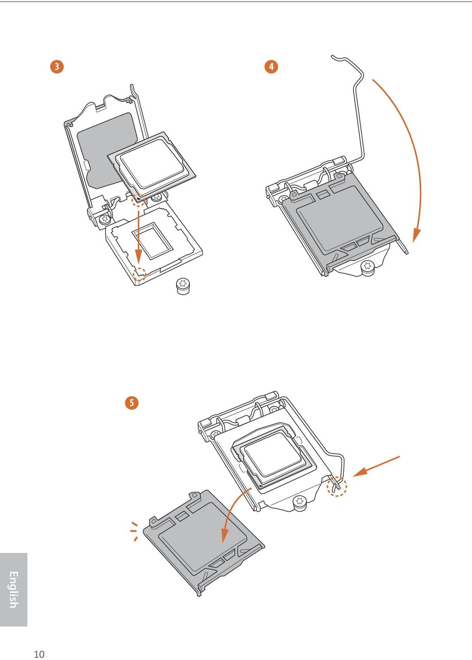
15 B85M-DGS Please save and replace the cover if the processor is removed. The cover must be placed if you wish to return the motherboard for after service. 11

16 2.2 Installing the CPU Fan and Heatsink 1 2 CPU_FAN 12

17 B85M-DGS 2.3 Installing Memory Modules (DIMM) This motherboard provides two 240-pin DDR3 (Double Data Rate 3) DIMM slots, and supports Dual Channel Memory Technology. 1. For dual channel configuration, you always need to install identical (the same brand, speed, size and chip-type) DDR3 DIMM pairs. 2. It is unable to activate Dual Channel Memory Technology with only one memory module installed. 3. It is not allowed to install a DDR or DDR2 memory module into a DDR3 slot; otherwise, this motherboard and DIMM may be damaged. The DIMM only fits in one correct orientation. It will cause permanent damage to the motherboard and the DIMM if you force the DIMM into the slot at incorrect orientation. 13

18

19 B85M-DGS 2.4 Expansion Slots (PCI Express Slots) There are 2 PCI Express slots on the motherboard. Before installing an expansion card, please make sure that the power supply is switched off or the power cord is unplugged. Please read the documentation of the expansion card and make necessary hardware settings for the card before you start the installation. PCIe slots: PCIE1 (PCIe 3.0 x16 slot) is used for PCI Express x16 lane width graphics cards. PCIE2 (PCIe 2.0 x1 slot) is used for PCI Express x1 lane width graphics cards. 15
 is used for PCI Express x16 lane width graphics cards. PCIE2 (PCIe 2.")
20 2.5 Jumpers Setup The illustration shows how jumpers are setup. When the jumper cap is placed on the pins, the jumper is Short. If no jumper cap is placed on the pins, the jumper is Open. The illustration shows a 3-pin jumper whose pin1 and pin2 are Short when a jumper cap is placed on these 2 pins. Clear CMOS Jumper (CLRCMOS1) (see p.5, No. 11) Default Clear CMOS CLRCMOS1 allows you to clear the data in CMOS. To clear and reset the system parameters to default setup, please turn off the computer and unplug the power cord from the power supply. After waiting for 15 seconds, use a jumper cap to short pin2 and pin3 on CLRCMOS1 for 5 seconds. However, please do not clear the CMOS right after you update the BIOS. If you need to clear the CMOS when you just finish updating the BIOS, you must boot up the system first, and then shut it down before you do the clear-cmos action. Please be noted that the password, date, time, and user default profile will be cleared only if the CMOS battery is removed. If you clear the CMOS, the case open may be detected. Please adjust the BIOS option Clear Status to clear the record of previous chassis intrusion status. 16

21 B85M-DGS 2.6 Onboard Headers and Connectors Onboard headers and connectors are NOT jumpers. Do NOT place jumper caps over these headers and connectors. Placing jumper caps over the headers and connectors will cause permanent damage to the motherboard. System Panel Header (9-pin PANEL1) (see p.5, No. 12) PLED+ PLED- PWRBTN# GND 1 GND RESET# GND HDLED- HDLED+ Connect the power switch, reset switch and system status indicator on the chassis to this header according to the pin assignments below. Note the positive and negative pins before connecting the cables. PWRBTN (Power Switch): Connect to the power switch on the chassis front panel. You may configure the way to turn off your system using the power switch. RESET (Reset Switch): Connect to the reset switch on the chassis front panel. Press the reset switch to restart the computer if the computer freezes and fails to perform a normal restart. PLED (System Power LED): Connect to the power status indicator on the chassis front panel. The LED is on when the system is operating. The LED keeps blinking when the system is in S1/S3 sleep state. The LED is off when the system is in S4 sleep state or powered off (S5). HDLED (Hard Drive Activity LED): Connect to the hard drive activity LED on the chassis front panel. The LED is on when the hard drive is reading or writing data. The front panel design may differ by chassis. A front panel module mainly consists of power switch, reset switch, power LED, hard drive activity LED, speaker and etc. When connecting your chassis front panel module to this header, make sure the wire assignments and the pin assignments are matched correctly. 17
22 Serial ATA3 Connectors (SATA3_0: see p.5, No. 8) (SATA3_1: see p.5, No. 9) (SATA3_2: see p.5, No. 7) (SATA3_3: see p.5, No. 6) SATA3_3 SATA3_1 SATA3_2 SATA3_0 These four SATA3 connectors support SATA data cables for internal storage devices with up to 6.0 Gb/s data transfer rate. USB 2.0 Headers (9-pin USB4_5) (see p.5, No. 16) (9-pin USB6_7) (see p.5, No. 14) USB_PWR P- P+ GND DUMMY 1 GND P+ P- USB_PWR Besides four USB 2.0 ports on the I/O panel, there are two headers on this motherboard. Each USB 2.0 header can support two ports. USB 3.0 Header (19-pin USB3_2_3) (see p.5, No. 10) IntA_PB_SSRX- Vbus IntA_PA_SSRX- IntA_PA_SSRX+ GND IntA_PA_SSTX- IntA_PA_SSTX+ GND IntA_PA_D- IntA_PA_D+ 1 Vbus IntA_PB_SSTX- IntA_PB_SSRX+ GND IntA_PB_D- IntA_PB_SSTX+ GND IntA_PB_D+ Dummy Besides two USB 3.0 ports on the I/O panel, there is one header on this motherboard. Each USB 3.0 header can support two ports. Front Panel Audio Header (9-pin HD_AUDIO1) (see p.5, No. 21) 1 GND PRESENCE# MIC_RET OUT_RET OUT2_L J_SENSE OUT2_R MIC2_R MIC2_L This header is for connecting audio devices to the front audio panel. 18
23 B85M-DGS 1. High Definition Audio supports Jack Sensing, but the panel wire on the chassis must support HDA to function correctly. Please follow the instructions in our manual and chassis manual to install your system. 2. If you use an AC 97 audio panel, please install it to the front panel audio header by the steps below: A. Connect Mic_IN (MIC) to MIC2_L. B. Connect Audio_R (RIN) to OUT2_R and Audio_L (LIN) to OUT2_L. C. Connect Ground (GND) to Ground (GND). D. MIC_RET and OUT_RET are for the HD audio panel only. You don t need to connect them for the AC 97 audio panel. E. To activate the front mic, go to the FrontMic Tab in the Realtek Control panel and adjust Recording Volume. Chassis Speaker Header (4-pin SPEAKER1) (see p.5, No. 15) DUMMY SPEAKER 1 +5V DUMMY Please connect the chassis speaker to this header. Chassis and Power Fan Connectors (4-pin CHA_FAN1) (see p.5, No. 17) FAN_SPEED_CONTROL FAN_SPEED +12V GND Please connect fan cables to the fan connectors and match the black wire to the ground pin. (3-pin PWR_FAN1) (see p.5, No. 3) GND +12V FAN_SPEED CPU Fan Connector (4-pin CPU_FAN1) (see p.5, No. 1) GND +12V FAN_SPEED FAN_SPEED_CONTROL This motherboard provides a 4-Pin CPU fan (Quiet Fan) connector. If you plan to connect a 3-Pin CPU fan, please connect it to Pin 1-3. ATX Power Connector (24-pin ATXPWR1) (see p.5, No. 5) This motherboard provides a 24-pin ATX power connector. To use a 20-pin ATX power supply, please plug it along Pin 1 and Pin
24 ATX 12V Power Connector (4-pin ATX12V1) (see p.5, No. 2) Please connect an ATX 12V power supply to this connector. Serial Port Header (9-pin COM1) (see p.5, No. 19) 1 RRXD1 DDTR#1 DDSR#1 CCTS#1 RRI#1 RRTS#1 GND TTXD1 DDCD#1 This COM1 header supports a serial port module. Chassis Intrusion Header (2-pin CI1) (see p.5, No. 20) 1 GND Signal This motherboard supports CASE OPEN detection feature that detects if the chassis cove has been removed. This feature requires a chassis with chassis intrusion detection design. TPM Header (17-pin TPMS1) (see p.5, No. 13) 1 GND PCICLK FRAME SMB_CLK_MAIN SMB_DATA_MAIN LAD2 LAD1 GND PCIRST# LAD3 +3V LAD0 S_PWRDWN# SERIRQ# GND +3VSB GND This connector supports Trusted Platform Module (TPM) system, which can securely store keys, digital certificates, passwords, and data. A TPM system also helps enhance network security, protects digital identities, and ensures platform integrity. 20
25 B85M-DGS Print Port Header (25-pin LPT1) (see p.5, No. 18) AFD# ERROR# PINIT# SLIN# 1 STB# SPD0SPD1 GND SPD2 SPD3 SPD4 SPD5SPD6SPD7 ACK# BUSYPESLCT This is an interface for print port cable that allows convenient connection of printer devices. 21
26 Chapter 3 Software and Utilities Operation 3.1 Installing Drivers The Support CD that comes with the motherboard contains necessary drivers and useful utilities that enhance the motherboard s features. Running The Support CD To begin using the support CD, insert the CD into your CD-ROM drive. The CD automatically displays the Main Menu if AUTORUN is enabled in your computer. If the Main Menu does not appear automatically, locate and double click on the file ASRSETUP.EXE in the Support CD to display the menu. Drivers Menu The drivers compatible to your system will be auto-detected and listed on the support CD driver page. Please click Install All or follow the order from top to bottom to install those required drivers. Therefore, the drivers you install can work properly. Utilities Menu The Utilities Menu shows the application software that the motherboard supports. Click on a specific item then follow the installation wizard to install it. To improve Windows 7 compatibility, please download and install the following hot fix provided by Microsoft. KB : 22
27 B85M-DGS 3.2 A-Tuning A-Tuning is ASRock s multi purpose software suite with a new interface, more new features and improved utilities, including XFast RAM, Dehumidifier, Good Night LED, FAN-Tastic Tuning, OC Tweaker and a whole lot more Installing A-Tuning When you install the all-in-one driver to your system from ASRock s support CD, A-Tuning will be auto-installed as well. After the installation, you will find the icon A-Tuning on your desktop. Double-click the A-Tuning icon, A-Tuning main menu will pop up Using A-Tuning There are six sections in A-Tuning main menu: Operation Mode, Tools, OC Tweaker, System Info, Live Update, Tech Service and Settings. Operation Mode Choose an operation mode for your computer. 23
28 Tools Various tools and utilities. XFast RAM Boost the system s performance and extend the HDD s or SDD s lifespan! Create a hidden partition, then assign which files should be stored in the RAM drive. XFast LAN Boost the speed of your internet connection! Select a specific mode for making the designated program's priority highest. Fast Boot Fast Boot minimizes your computer's boot time. Please note that Ultra Fast mode is only supported by Windows 8.1/8 and the VBIOS must support UEFI GOP if you are using an external graphics card. OMG Schedule the starting and ending hours of Internet access granted to other users. Place X marks on the time table to disable the Internet. Good Night LED Switch off the Power/HDD LEDs when the system is on, and automatically switch off the Power and Keyboard LEDs when the system enters into Standby/Hibernation mode. 24
29 B85M-DGS FAN-Tastic Tuning Configure up to five different fan speeds using the graph. The fans will automatically shift to the next speed level when the assigned temperature is met. Dehumidifier Prevent motherboard damages due to dampness. Enable this function and configure the period of time until the computer powers on, and the duration of the dehumidifying process. USB Key Plug in the USB Key and let your computer log in to windows automatically! Disk Health Report Disk Health Report is a hard disk health monitoring utility that displays detailed HDD information, such as hard disk model, serial number, firmware, power on count, power on hours, S.M.A.R.T. values, current temperature, etc. HDD, SSD and optical disk drives are all supported. The health status block displays Good (in green color), Caution (in yellow color) or Bad (in red color). Click on the health status icon to configure settings for an alert to be triggered. 25
30 OC Tweaker Configurations for overclocking the system. System Info View information about the system. *The System Browser tab may not appear for certain models. 26
31 B85M-DGS Live Update Check for newer versions of BIOS or drivers. Tech Service Contact Tech Service if you have problems with your computer. Please leave your contact information along with details of the problem. 27
32 Settings Configure ASRock A-Tuning. Click to select "Auto run at Windows Startup" if you want A-Tuning to be launched when you start up the Windows operating system. 28
33 B85M-DGS 3.3 Intel Rapid Start Technology Intel Rapid Start Technology enables your system to wake up faster from deep sleep, saving time and power consumption. Feel secure to know that your system will resume to working condition even if an unexpected power loss happens while the PC is in sleep mode System Requirements Confirm whether your motherboard supports this feature. Operating system: Microsoft Windows 8.1/8/7 (32- or 64-bit edition) Set the SATA mode to AHCI. If Windows 8.1/8/7 is already installed under IDE mode, directly changing the SATA mode to AHCI may cause Windows 8/7 to crash while booting. If your system is not in AHCI mode, please follow the instructions below. There are certain risks. Please backup any important data before operating to avoid loss. 1. Press Win + R simultaneously in Windows 8/7, type "Regedit" into the word box then click OK. 2. Enter into HKEY_LOCAL_MACHINE\SYSTEM\CurrentControlSet\services\ msahci in Windows Registry Editor. Double click on the value Start and change the value from 3 into 0. Click on OK. 29

34 3. Exit the Registry Editor window and restart the computer. 4. Press F2 to enter BIOS, then go to Advanced > Storage Configuration and change SATA Mode to AHCI. Press F10 to save changes and exit. 5. Enter Windows 8/7. Windows will discover the new device and install AHCI drivers automatically Setup Guide Configuring Rapid Start Step 1 Run ASRock Rapid Start utility from Start -> All Programs -> ASRock Utility. Step 2 If you have more than one hard drives in your system, you must select one, then choose the Partition Size desired for your hidden partition and click on Create. The system will automatically create a hidden partition according to your settings. If there are SSD s installed into your system, it is recommended to create the partition on the SSD. 30
35 B85M-DGS Step 3 When prompted to restart after the setup, click Yes to reboot. Step 4 Double-click the Intel Rapid Start Technology Manager icon system tray. in the Windows 31


36 Step 5 Make sure Rapid Start is on. Drag the slider to configure the time. For example, if the timer value is set to ten minutes, the system will enable Rapid Start mode after entering sleep state for ten minutes. If the timer is set to 0 minutes, Windows will immediately enable Rapid Start mode as it enters sleep state. Using Rapid Start 1. You may shut down the computer without terminating the applications or files you are executing currently. Click on Windows Start > the arrow next to Shut down, and click on Sleep. 2. Windows system will enter sleep state. 3. According to your settings in Rapid Start Technology Manager, the system will automatically wake up and enable Rapid Start mode after entering sleep 32
37 B85M-DGS state for a period of time. The power of the computer in Rapid Start mode can be cut off, it will not cause data loss of the programs or files you were executing before entering sleep state. 4. When you wish to continue to use the computer just hit the power button, the system will rapidly return to Windows, the programs and files which you were using before entering sleep state will be accessible immediately. 33

38 3.4 Intel Smart Connect Technology Intel Smart Connect Technology is a feature that periodically wakes your computer from Windows sleep state to refresh or social networking applications. It saves your waiting time and keeps the content always up-to-date System Requirements Confirm whether your motherboard supports this feature. Operating system: Microsoft Windows 8.1/8/7 (32- or 64-bit edition) Set the SATA mode to AHCI. If Windows 8.1/8/7 is already installed under IDE mode, directly changing the SATA mode to AHCI may cause Windows 8/7 to crash while booting. If your system is not in AHCI mode, please follow the instructions below. There are certain risks. Please backup any important data before operating to avoid loss. 1. Press Win + R simultaneously in Windows 8.1/8/7, type "Regedit" into the word box then click OK. 2. Enter into HKEY_LOCAL_MACHINE\SYSTEM\CurrentControlSet\services\ msahci in Windows Registry Editor. Double click on the value Start and change the value from 3 into 0. Click on OK. 34
39 B85M-DGS Setup Guide Installing ASRock Smart Connect Utility Step 1 Install ASRock Smart Connect Utility, which is located in the folder at the following path of the Support CD: \ ASRock Utility > Smart Connect. Step 2 Once installed, run ASRock Smart Connect from your desktop or go to Windows Start -> All Programs -> ASRock Utility. 35


40 Step 3 Click the Add button. Take Foxmail as an example, add Foxmail to the Application list. Step 4 Select Foxmail from the Application List, then click the arrow pointing right to add this application to the Smart Connect List. Step 5 Click Apply to enable Smart Connect. 36
41 B85M-DGS Step 6 Double-click the Intel Smart Connect Technology Manager icon Windows system tray. in the Step 7 Drag the slider to configure how often the system will connect to the network to download updates. Shorter durations will provide more frequent updates, but may cause more power consumption. Using Smart Connect 1. Keep the applications which you wish to connect to the internet and receive updates while the system is in sleep state running. Foxmail for instance, keep Foxmail running. 2. Click on Windows Start -> the arrow next to Shut down, and click on Sleep. 3. Windows system will enter sleep state. 37
42 4. The system will wake up from sleep state periodically, and then start to update Foxmail. The screen will not display anything so the computer can maintain minimum power usage. Afterwards, the system will automatically return to sleep state again. 5. Upon waking up the system, you will find the new mail that were sent to you during sleep state are already updated and ready to be read in Foxmail. 38
43 B85M-DGS 3.5 ASRock Cloud ASRock Cloud makes your mobile devices connect to your PC seamlessly! Have you ever been in a situation where you emergently needed certain files in your computer, however the computer was gazillion miles away out of reach? ASRock Cloud includes several technologies and software solutions for remotely controlling your computer, even if the computer is in off mode. For ASRock motherboards with a Realtek LAN chip, ASRock Cloud allows users to remotely wake up their computers via the internet by using a secondary device, such as a smartphone or tablet. Users may use Orbweb.ME Professional to remotely wake up and control their computers, or they could wake up the computer then use any other preferred remote desktop application. This motherboard supports Wake-On-WAN with the onboard Realtek LAN, so you can connect with your PC from anywhere in the world. You will be able to power your PC on or turn it off, monitor and take control of it remotely with another smartphone, tablet or computer. *ASRock Cloud is supported on Windows 8.1 / 7. 39


44 3.5.1 Realtek Wake-On-WAN Realtek Wake-On-WAN allows you to wake up and remote control your home computer from sleep or shutdown state. Before configuring this feature, verify the followings on your host computer: Make sure that the "PCIE Devices Power On" is enabled in UEFI SETUP UTILITY > Advanced > ACPI Configuration. *The UEFI screen is for reference only. The actual screen may differ by model. Make sure that the "Shutdown Wake-On-Lan" is enabled in Device Manager > Network Adapters > Realtek PCIe GBE Family Controller > Advanced. 40
45 B85M-DGS Configuring and Using Orbweb.ME Professional Orbweb.ME Professional is a remote control software allowing you to easily access and control the remote host installed with the Orbweb.ME Professional host software. Installing Orbweb.ME Professional on the Host Computer You can find the Orbweb.ME Professional host software in the Support CD or just download it from Step 1 Click on the Orbweb.ME Professional installer package file to start installation. Step 2 Follow the onscreen instructions to complete the installation. Step 3 When installation completes, reboot the computer. Signing Up for Host Computer Registration Step 1 Double-click the Orbweb.ME Professional icon on your desktop. Step 2 On the Orbweb.ME Portal login page, click Sign Up to create an Orbweb.ME account and name your host computer. 41
46 Step 3 You will receive a verification . Follow the steps in the to verify your account. After verifying your account, you can access your PC through web browsers at On the Account Verified page, if you click Go to My Computers, you will see the Orbweb. ME portal page as a client. Setting Up Shared Folders on Host Computer Step 1 Double-click the Orbweb.ME Professional icon on your desktop. Or, if you just finished signing up for your host computer, you can click Configure this computer in the screen to begin. Step 2 Click Folder Settings tab and the default shared folders display. To add a folder, click. Select a folder to add it into Orbweb.ME. Then click Save. You can access the documents in these shared folders on the host computer remotely through Xplorer from your client device. 42
47 B85M-DGS REMOTE ACCESS FROM A CLIENT DEVICE The lastest version of Java is required to be installed to use the Remote Desktop and Xplorer functions. Using Remote Wake-Up Remote Wake-Up allows you to remotely put your host computer to sleep and wake your host computer up from a client device. If you use a motherboard with dual LAN ports, please disable one of the LAN ports to use the Remote Wake-Up function. To do so, go to Control Panel > Network and Sharing Center > Manage Network Connections, right-click Local Area Connections and select Disable. For Windows PC users: Step 1 Go to Orbweb.ME portal login page: Step 2 Log in with your Orbweb.ME account and password. Step 3 Find the host computer from the list by the computer name you give. Online / Green Ready to Connect / Blue Online / Blue Offline / Gray Unable to Connect / Gray Wakable / Red Wakable mode 43
48 Step 4 Click and power options appear. Click to select Restart, Sleep or Shut Down. Select Restart from the options to restart your host computer remotely. When you select Sleep or Shut Down, if the host device is WOW(Wake-On-Wan) compatible, you can put your host computer to sleep (S3/S4) or shut down your host computer (S5) remotely. The host status in the Status column shows offline and ready to be awaked and the power option shows wakable. To wake up the computer, click. Please be noted that if the host device is not WOW compatible, the host status icon will turn offline and the power option icon will disappear. You have to physically wake up computer in order to bring power option icon back to online. For ios or Android Mobile Devices users: Download and install Orbweb.ME Professional app from the App Store (ios) or Play Store (Android). Step 1 Tap the Orbweb.ME Professional app icon to launch it. Step 2 Log in with your Orbweb.ME account and password. Step 3 Tap the Power Options icon and power options appear. Tap to select Restart, Sleep or Shutdown. 44
49 B85M-DGS Please be noted that if the host device is not WOW compatible, the host status icon will turn offline and the power option icon will dissappear. You have to physically wake up computer in order to bring power option icon back to online. Using Remote Desktop Remote Desktop allows you to remotely access your host computer from a client device. For Windows PC users: Step 1 Go to Orbweb.ME portal login page: Step 2 Log in with your Orbweb.ME account and password. Step 3 Click the Connect icon. Step 4 Click on Remote Desktop. If the Remote Desktop Connection dialog appears, click Connect to continue. Step 5 Enter the Windows password to log in and you will see the desktop of your host computer. Please refer to the user manual of the Orbweb.ME Professional for more instructions on how to use Orbweb.ME Professional. 45
50 For ios or Android Mobile Devices users: Download and install Orbweb.ME Professional app from the App Store (ios) or Play Store (Android). Step 1 Tap the Orbweb.ME Professional app icon to launch it. Step 2 Log in with your Orbweb.ME account and password. Step 3 Tap the host computer name that you want to access under the Remote Desktop section. Step 4 Enter the Windows password to log in and you will see the desktop of your host computer. 46
51 B85M-DGS Using Xplorer Xplorer allows you to remotely access documents on your host computer from a client device. For Windows PC users: Step 1 Go to Orbweb.ME portal login page: Step 2 Log in with your Orbweb.ME account and password. Step 3 Click the Connect icon. Step 4 Click on Xplorer. Step 5 Root directory displays. Click on a folder name to open the folder. Step 6 Click on a file name to preivew the file. You can also delete, rename, move, and copy a selected file. For more instructions on how to use Xplorer, refer to the user manual of the Orbweb.ME Professional. 47
52 For ios or Android Mobile Devices users: Download and install Orbweb.ME Professional app from the App Store (ios) or Play Store (Android). Step 1 Tap the Orbweb.ME Professional app icon to launch it. Step 2 Log in with your Orbweb.ME account and password. Step 3 Tap the Connect icon. Step 4 Tap a folder name under the Xplorer section and you can see the files in this folder. Tap a file name to preivew the file. You can also delete, rename, move, and copy a selected file. For more instructions on how to use Xplorer, refer to the user manual of the Orbweb.ME Professional. Tutorial Video 48
53 B85M-DGS 3.6 ASRock APP Shop The ASRock APP Shop is an online store for purchasing and downloading software applications for your ASRock computer. You can install various apps and support utilities quickly and easily, and optimize your system and keep your motherboard up to date simply with a few clicks. Double-click on your desktop to access ASRock APP Shop utility. *You need to be connected to the Internet to download apps from the ASRock APP Shop UI Overview Category Panel Hot News Information Panel Category Panel: The category panel contains several category tabs or buttons that when selected the information panel below displays the relative information. Information Panel: The information panel in the center displays data about the currently selected category and allows users to perform job-related tasks. Hot News: The hot news section displays the various latest news. Click on the image to visit the website of the selected news and know more. 49
54 3.6.2 Apps When the "Apps" tab is selected, you will see all the available apps on screen for you to download. Installing an App Step 1 Find the app you want to install. The most recommended app appears on the left side of the screen. The other various apps are shown on the right. Please scroll up and down to see more apps listed. You can check the price of the app and whether you have already intalled it or not. - The red icon displays the price or "Free" if the app is free of charge. - The green "Installed" icon means the app is installed on your computer. Step 2 Click on the app icon to see more details about the selected app. 50
55 B85M-DGS Step 3 If you want to install the app, click on the red icon to start downloading. Step 4 When installation completes, you can find the green "Installed" icon appears on the upper right corner. To uninstall it, simply click on the trash can icon. *The trash icon may not appear for certain apps. 51
56 Upgrading an App You can only upgrade the apps you have already installed. When there is an available new version for your app, you will find the mark of "New Version" appears below the installed app icon. Step 1 Click on the app icon to see more details. Step 2 Click on the yellow icon to start upgrading. 52
57 B85M-DGS BIOS & Drivers Installing BIOS or Drivers When the "BIOS & Drivers" tab is selected, you will see a list of recommended or critical updates for the BIOS or drivers. Please update them all soon. Step 1 Please check the item information before update. Click on to see more details. Step 2 Click to select one or more items you want to update. Step 3 Click Update to start the update process. 53
58 3.6.4 Setting In the "Setting" page, you can change the language, select the server location, and determine if you want to automatically run the ASRock APP Shop on Windows startup. 54
59 B85M-DGS 3.7 Start8 For those Windows 8 users who miss the Start Menu, Start8 is an ideal solution that brings back the familiar Start Menu along with added customizations for greater efficiency Installing Start8 Install Start8, which is located in the folder at the following path of the Support CD: \ ASRock Utility > Start Configuring Start8 Style Select between the Windows 7 style and Windows 8 style Start Menu. Then select the theme of the Start Menu and customize the style of the Start icon. 55

60 Configure Configure provides configuration options, including icon sizes, which shortcuts you want Start Menu to display, quick access to recently used apps, the functionality of the power button, and more. Control 56

61 B85M-DGS Control lets you configure what a click on the start button or a press on the Windows key does. Desktop Desktop allows you to disable the hot corners when you are working on the desktop. It also lets you choose whether or not the system boots directly into desktop mode and bypass the Metro user interface. About Displays information about Start8. 57
Copyright Notice: Disclaimer: CALIFORNIA, USA ONLY. Version 1.0 Published October 2013 Copyright 2013 ASRock INC. All rights reserved.
 User Manual Version 1.0 Published October 2013 Copyright 2013 ASRock INC. All rights reserved. Copyright Notice: No part of this documentation may be reproduced, transcribed, transmitted, or translated
Copyright Notice: Disclaimer: CALIFORNIA, USA ONLY. Version 1.1 Published November 2014 Copyright 2014 ASRock INC. All rights reserved.
 B85 Anniversary B85 Anniversary Version 1.1 Published November 2014 Copyright 2014 ASRock INC. All rights reserved. Copyright Notice: No part of this documentation may be reproduced, transcribed, transmitted,
Copyright Notice: Disclaimer: CALIFORNIA, USA ONLY. Version 1.1 Published October 2014 Copyright 2014 ASRock INC. All rights reserved.
 B85M Pro3 B85M Pro3 Version 1.1 Published October 2014 Copyright 2014 ASRock INC. All rights reserved. Copyright Notice: No part of this documentation may be reproduced, transcribed, transmitted, or translated
Copyright Notice: Disclaimer: CALIFORNIA, USA ONLY. Version 1.0 Published August 2014 Copyright 2014 ASRock INC. All rights reserved.
 H97 Anniversary H97 Anniversary Version 1.0 Published August 2014 Copyright 2014 ASRock INC. All rights reserved. Copyright Notice: No part of this documentation may be reproduced, transcribed, transmitted,
Copyright Notice: Disclaimer: CALIFORNIA, USA ONLY. Version 1.0 Published March 2013 Copyright 2013 ASRock INC. All rights reserved.
 User Manual Version 1.0 Published March 2013 Copyright 2013 ASRock INC. All rights reserved. Copyright Notice: No part of this documentation may be reproduced, transcribed, transmitted, or translated in
H97M-E/CSM. Chipset. Memory. Graphic. Expansion Slots. Storage
 H97M-E/CSM Intel Socket 1150 for the 5 th /New 4 th /4 th Generation Core i7/core i5/core i3/pentium /Celeron Processors Supports Intel 22 nm CPU Supports Intel Turbo Boost Technology 2.0 * The Intel Turbo
Copyright Notice: Disclaimer: CALIFORNIA, USA ONLY. Version 1.0 Published September 2013 Copyright 2013 ASRock INC. All rights reserved.
 User Manual Version 1.0 Published September 2013 Copyright 2013 ASRock INC. All rights reserved. Copyright Notice: No part of this documentation may be reproduced, transcribed, transmitted, or translated
Copyright Notice: Disclaimer: CALIFORNIA, USA ONLY. Version 1.0 Published August 2013 Copyright 2013 ASRock INC. All rights reserved.
 User Manual Version 1.0 Published August 2013 Copyright 2013 ASRock INC. All rights reserved. Copyright Notice: No part of this documentation may be reproduced, transcribed, transmitted, or translated
Copyright Notice: Disclaimer: CALIFORNIA, USA ONLY. Version 1.1 Published November 2014 Copyright 2014 ASRock INC. All rights reserved.
 Z97M-ITX/ac Z97M Pro4 Version 1.1 Published November 2014 Copyright 2014 ASRock INC. All rights reserved. Copyright Notice: No part of this documentation may be reproduced, transcribed, transmitted, or
Copyright Notice: Disclaimer: CALIFORNIA, USA ONLY. Version 1.0 Published July 2014 Copyright 2014 ASRock INC. All rights reserved.
 FM2A78M-HD+ R2.0 FM2A78M-HD+ R2.0 Version 1.0 Published July 2014 Copyright 2014 ASRock INC. All rights reserved. Copyright Notice: No part of this documentation may be reproduced, transcribed, transmitted,
Copyright Notice: Disclaimer: CALIFORNIA, USA ONLY. Version 1.0 Published March 2013 Copyright 2013 ASRock INC. All rights reserved.
 User Manual Version 1.0 Published March 2013 Copyright 2013 ASRock INC. All rights reserved. Copyright Notice: No part of this documentation may be reproduced, transcribed, transmitted, or translated in
PV530-ITX. www.asrock.com. Product Brief. Detail Specification. VIA PV530 CPU + VX900 Chipset
 Detail Specification Platform - Mini-ITX Form Factor: 6.7-in x 6.7-in, 17.0 cm x 17.0 cm - Solid Capacitor for CPU power CPU Chipset Memory - VIA PV530 Processor (1.8 GHz) - Supports FSB800 MHz - Supports
IPMIP-GS Series Motherboard layout reference
 IPMIP-GS Series Motherboard layout reference Contents Specifications summary Motherboard layout Rear panel s Internal s This manual is meant as a general reference guide. Refer to the product itself for
Ultra Thin Client TC-401 TC-402. Users s Guide
 Ultra Thin Client TC-401 TC-402 Users s Guide CONTENT 1. OVERVIEW... 3 1.1 HARDWARE SPECIFICATION... 3 1.2 SOFTWARE OVERVIEW... 4 1.3 HARDWARE OVERVIEW...5 1.4 NETWORK CONNECTION... 7 2. INSTALLING THE
USB 2.0 VGA ADAPTER USER MANUAL
 USB 2.0 VGA ADAPTER USER MANUAL CONTENTS INTRODUCTION... 3 FEATURES... 3 SYSTEM REQUIREMENTS... 3 PACKAGE CONTENTS... 3 SUPPORTED COMMON DISPLAY RESOLUTION... 4 TECHNICAL SPECIFICATIONS... 4 INSTALLATION
Using GIGABYTE Notebook for the First Time
 P34 V6.0 Congratulations on your purchase of the GIGABYTE Notebook. This manual will help you to get started with setting up your notebook. The final product configuration depends on the model at the point
Using GIGABYTE Notebook for the First Time
 Congratulations on your purchase of the GIGABYTE Notebook P7! This Manual will help you to get started with setting up your notebook. For more detailed information, please visit our website at http://www.gigabyte.com.
AD2550B-ITX. User Manual. Version 1.1 Published June 2013 Copyright 2013 ASRock INC. All rights reserved.
 AD2550B-ITX User Manual Version 1.1 Published June 2013 Copyright 2013 ASRock INC. All rights reserved. 1 Copyright Notice: No part of this manual may be reproduced, transcribed, transmitted, or translated
Copyright Notice: Disclaimer: CALIFORNIA, USA ONLY. Version 1.0 Published May 2014 Copyright 2014 ASRock INC. All rights reserved.
 Z97 Extreme9 Z97 Extreme9 Version 1.0 Published May 2014 Copyright 2014 ASRock INC. All rights reserved. Copyright Notice: No part of this documentation may be reproduced, transcribed, transmitted, or
Getting Started. Chapter 1
 Chapter 1 Getting Started Thank you for choosing the 7728 v2.x Series Micro-ATX mainboard. The 7728 v2.x Series mainboards are based on Intel H61 chipsets for optimal system efficiency. Designed to fit
IPN73-BA Motherboard layout reference Contents
 IPN73-BA Motherboard layout reference Contents Specifications summary Motherboard layout Rear panel connectors Function selectors Status indicators Internal connectors February 2008 Specifications summary
Copyright Notice: Disclaimer: CALIFORNIA, USA ONLY. Version 1.2 Published October 2014 Copyright 2014 ASRock INC. All rights reserved.
 Version 1.2 Published October 2014 Copyright 2014 ASRock INC. All rights reserved. Copyright Notice: No part of this documentation may be reproduced, transcribed, transmitted, or translated in any language,
Using AORUS Notebook for the First Time
 V2.0 Congratulations on your purchase of the AORUS Notebook! This Manual will help you to get started with setting up your notebook. For more detailed information, please visit our website at http://www.aorus.com.
Copyright Notice: Disclaimer: CALIFORNIA, USA ONLY. Version 1.1 Published October 2014 Copyright 2014 ASRock INC. All rights reserved.
 User Manual Version 1.1 Published October 2014 Copyright 2014 ASRock INC. All rights reserved. Copyright Notice: No part of this documentation may be reproduced, transcribed, transmitted, or translated
760GM-GS3 / 760GM-S3. User Manual. Version 1.0 Published September 2010 Copyright 2010 ASRock INC. All rights reserved.
 760GM-GS3 / 760GM-S3 User Manual Version 1.0 Published September 2010 Copyright 2010 ASRock INC. All rights reserved. 1 Copyright Notice: No part of this manual may be reproduced, transcribed, transmitted,
Using GIGABYTE Notebook for the First Time
 P55 V3.0 Congratulations on your purchase of the GIGABYTE Notebook. This manual will help you to get started with setting up your notebook. The final product configuration depends on the model at the point
H61M-DGS. User Manual. Version 1.0 Published December 2011 Copyright 2011 ASRock INC. All rights reserved.
 H61M-DGS User Manual Version 1.0 Published December 2011 Copyright 2011 ASRock INC. All rights reserved. 1 Copyright Notice: No part of this manual may be reproduced, transcribed, transmitted, or translated
Using GIGABYTE Notebook for the First Time
 Congratulations on your purchase of the GIGABYTE Notebook! This Manual will help you to get started with setting up your notebook. For more detailed information, please visit our website at http://www.gigabyte.com.
Copyright Notice: Disclaimer: CALIFORNIA, USA ONLY. Version 1.0 Published May 2014 Copyright 2014 ASRock INC. All rights reserved.
 User Manual Version 1.0 Published May 2014 Copyright 2014 ASRock INC. All rights reserved. Copyright Notice: No part of this documentation may be reproduced, transcribed, transmitted, or translated in
A75M-HVS. User Manual. Version 1.1 Published June 2011 Copyright 2011 ASRock INC. All rights reserved.
 A75M-HVS User Manual Version 1.1 Published June 2011 Copyright 2011 ASRock INC. All rights reserved. 1 Copyright Notice: No part of this manual may be reproduced, transcribed, transmitted, or translated
AP480-S Motherboard layout reference Contents
 AP80-S Motherboard layout reference Contents Specifications summary Motherboard layout Rear panel connectors Function selectors Internal connectors JUL 2008 Specifications summary CPU Chipset Front Side
N61P-GS / N61P-S. User Manual. Version 1.0 Published September 2008 Copyright 2008 ASRock INC. All rights reserved.
 N61P-GS / N61P-S User Manual Version 1.0 Published September 2008 Copyright 2008 ASRock INC. All rights reserved. 1 Copyright Notice: No part of this manual may be reproduced, transcribed, transmitted,
ENLTV-FM3. PCI TV Tuner Adapter with FM Radio. User s Guide
 ENLTV-FM3 PCI TV Tuner Adapter with FM Radio User s Guide User s Notice No part of this manual, including the products and software described in it, may be reproduced, transmitted, transcribed, stored
BIOS Update Release Notes
 BIOS Update Release Notes PRODUCTS: DH61BE, DH61CR, DH61DL, DH61WW, DH61SA, DH61ZE (Standard BIOS) BIOS Version 0120 - BEH6110H.86A.0120.2013.1112.1412 Date: November 12, 2013 ME Firmware: Ignition SKU
Copyright Notice: Disclaimer: CALIFORNIA, USA ONLY. Version 1.0 Published June 2015 Copyright 2015 ASRock INC. All rights reserved.
 Version 1.0 Published June 2015 Copyright 2015 ASRock INC. All rights reserved. Copyright Notice: No part of this documentation may be reproduced, transcribed, transmitted, or translated in any language,
ALiveNF5-eSATA2+ User Manual. Version 1.0 Published January 2007 Copyright 2007 ASRock INC. All rights reserved.
 ALiveNF5-eSATA2+ User Manual Version 1.0 Published January 2007 Copyright 2007 ASRock INC. All rights reserved. 1 Copyright Notice: No part of this manual may be reproduced, transcribed, transmitted, or
Using GIGABYTE Notebook for the First Time
 Congratulations on your purchase of the GIGABYTE Notebook. This manual will help you to get started with setting up your notebook. The final product configuration depends on the model at the point of your
EVGA Z97 Classified Specs and Initial Installation (Part 1)
") User Guide EVGA Z97 Classified Specs and Initial Installation (Part 1) - 1 - Table of Contents Before you Begin 3 Parts Not in the kit.4 Intentions of the kit 4 Motherboard Specifications 5 Unpacking and
User Guide EVGA Z97 Classified Specs and Initial Installation (Part 1) - 1 - Table of Contents Before you Begin 3 Parts Not in the kit.4 Intentions of the kit 4 Motherboard Specifications 5 Unpacking and
Z97-PRO GAMER Especificaciones
 Z97-PRO GAMER Especificaciones CPU Intel Socket 1150 for the 5 th /New 4 th /4 th Generation Core i7/core i5/core i3/pentium /Celeron Processors Supports Intel 22 nm CPU Supports Intel Turbo Boost Technology
Copyright Notice: Disclaimer: CALIFORNIA, USA ONLY. Version 1.0 Published June 2015 Copyright 2015 ASRock INC. All rights reserved.
 Version 1.0 Published June 2015 Copyright 2015 ASRock INC. All rights reserved. Copyright Notice: No part of this documentation may be reproduced, transcribed, transmitted, or translated in any language,
H61 Pro BTC. User Manual. Version 1.0 Published September 2013 Copyright 2013 ASRock INC. All rights reserved.
 H61 Pro BTC User Manual Version 1.0 Published September 2013 Copyright 2013 ASRock INC. All rights reserved. 1 Version 1.0 Published September 2013 Copyright 2013 ASRock INC. All rights reserved. Copyright
Copyright Notice: Disclaimer: CALIFORNIA, USA ONLY. Version 1.0 Published March 2013 Copyright 2013 ASRock INC. All rights reserved.
 User Manual Version 1.0 Published March 2013 Copyright 2013 ASRock INC. All rights reserved. Copyright Notice: No part of this documentation may be reproduced, transcribed, transmitted, or translated in
H61M-VG3 / H61M-VS3. User Manual. Version 1.0 Published October 2012 Copyright 2012 ASRock INC. All rights reserved.
 H61M-VG3 / H61M-VS3 User Manual Version 1.0 Published October 2012 Copyright 2012 ASRock INC. All rights reserved. 1 Copyright Notice: No part of this manual may be reproduced, transcribed, transmitted,
Copyright Notice: Disclaimer:
 User Manual Version 1.0 Published August 2013 Copyright 2013 ASRock INC. All rights reserved. Copyright Notice: No part of this documentation may be reproduced, transcribed, transmitted, or translated
N68-GE3 UCC. User Manual. Version 1.0 Published July 2010 Copyright 2010 ASRock INC. All rights reserved.
 N68-GE3 UCC User Manual Version 1.0 Published July 2010 Copyright 2010 ASRock INC. All rights reserved. 1 Copyright Notice: No part of this manual may be reproduced, transcribed, transmitted, or translated
Copyright Notice: Disclaimer: CALIFORNIA, USA ONLY. Version 1.1 Published May 2015 Copyright 2015 ASRock INC. All rights reserved.
 N3700-ITX N3150-ITX N3700-ITX N3150-ITX Version 1.1 Published May 2015 Copyright 2015 ASRock INC. All rights reserved. Copyright Notice: No part of this documentation may be reproduced, transcribed, transmitted,
N68PV-GS. User Manual. Version 1.0 Published September 2008 Copyright 2008 ASRock INC. All rights reserved.
 N68PV-GS User Manual Version 1.0 Published September 2008 Copyright 2008 ASRock INC. All rights reserved. 1 Copyright Notice: No part of this manual may be reproduced, transcribed, transmitted, or translated
XPC BIOS User Guide. For the : DS437T
 XPC BIOS User Guide For the : DS437T Shuttle XPC Installation Guide 2014 by Shuttle Inc. All Rights Reserved. Copyright No part of this publication may be reproduced, transcribed, stored in a retrieval
Getting Started. Version 3.1 Last updated 2014/3/10. Orbweb ME: Getting Started
 Information in this document is subject to change without notice. Companies, names, and data used in examples herein are fictitious unless otherwise noted. No part of this document may be reproduced or
P43R1600Twins-WiFi / P43R1600Twins-110dB / P43R1600Twins
 P43R1600Twins-WiFi / P43R1600Twins-110dB / P43R1600Twins User Manual Version 1.0 Published May 2008 Copyright 2008 ASRock INC. All rights reserved. 1 Copyright Notice: No part of this manual may be reproduced,
H61M-GS / H61M-S. User Manual. Version 1.1 Published May 2012 Copyright 2012 ASRock INC. All rights reserved.
 H61M-GS / H61M-S User Manual Version 1.1 Published May 2012 Copyright 2012 ASRock INC. All rights reserved. 1 Copyright Notice: No part of this manual may be reproduced, transcribed, transmitted, or translated
XPC Bios User Guide. For the : SZ77R5
 XPC Bios User Guide For the : SZ77R5 Shuttle XPC Installation Guide 2012 by Shuttle Inc. All Rights Reserved. Copyright No part of this publication may be reproduced, transcribed, stored in a retrieval
FM2A85X Extreme4-M. User Manual. Version 1.1 Published July 2013 Copyright 2013 ASRock INC. All rights reserved.
 FM2A85X Extreme4-M User Manual Version 1.1 Published July 2013 Copyright 2013 ASRock INC. All rights reserved. 1 Copyright Notice: No part of this manual may be reproduced, transcribed, transmitted, or
Serial ATA RAID PCI. User's Manual
 Serial ATA RAID PCI User's Manual Chapter 1 Introduction Table of Contents 1-1 Features and Benefits. 1 1-2 System Requirements. 1 Chapter 2 RAID Arrays 2-1 RAID Overview.. 2 2-1.1 RAID 0 (striping)...
User Guide Win7Zilla
 User Guide Win7Zilla Table of contents Section 1: Installation... 3 1.1 System Requirements... 3 1.2 Software Installation... 3 1.3 Uninstalling Win7Zilla software... 3 Section 2: Navigation... 4 2.1 Main
Features Reference. About Unified Communication System. Before Using This Machine. Starting a Meeting. What You Can Do During the Meeting
 Features Reference About Unified Communication System Before Using This Machine Starting a Meeting What You Can Do During the Meeting Leaving a Meeting Managing Address Book Changing Network Configuration
G31M-GS / G31M-S. User Manual. Version 2.0 Published June 2009 Copyright 2009 ASRock INC. All rights reserved.
 G3M-GS / G3M-S User Manual Version 2.0 Published June 2009 Copyright 2009 ASRock INC. All rights reserved. Copyright Notice: No part of this manual may be reproduced, transcribed, transmitted, or translated
M266A. User Manual. Version 3.0 Published July 2003 Copyright 2003 ASRock INC. All rights reserved.
 M266A User Manual Version 3.0 Published July 2003 Copyright 2003 ASRock INC. All rights reserved. 1 Copyright Notice: No part of this manual may be reproduced, transcribed, transmitted, or translated in
FM2A55M-DGS. User Manual. Version 1.0 Published August 2012 Copyright 2012 ASRock INC. All rights reserved.
 FM2A55M-DGS User Manual Version 1.0 Published August 2012 Copyright 2012 ASRock INC. All rights reserved. 1 Copyright Notice: No part of this manual may be reproduced, transcribed, transmitted, or translated
OPERATION MANUAL. MV-410RGB Layout Editor. Version 2.1- higher
 OPERATION MANUAL MV-410RGB Layout Editor Version 2.1- higher Table of Contents 1. Setup... 1 1-1. Overview... 1 1-2. System Requirements... 1 1-3. Operation Flow... 1 1-4. Installing MV-410RGB Layout
B75M-DGS. User Manual. Version 1.0 Published July 2012 Copyright 2012 ASRock INC. All rights reserved.
 B75M-DGS User Manual Version 1.0 Published July 2012 Copyright 2012 ASRock INC. All rights reserved. 1 Copyright Notice: No part of this manual may be reproduced, transcribed, transmitted, or translated
SSD Guru. Installation and User Guide. Software Version 1.4
 SSD Guru Installation and User Guide Software Version 1.4 Contents Welcome!............................................................................. 1 Key features.........................................................................
Copyright Notice: Disclaimer: CALIFORNIA, USA ONLY. Version 1.0 Published March 2013 Copyright 2013 ASRock INC. All rights reserved.
 User Manual Version 1.0 Published March 2013 Copyright 2013 ASRock INC. All rights reserved. Copyright Notice: No part of this documentation may be reproduced, transcribed, transmitted, or translated in
Lenovo IdeaCentre Q180 Series
 Machine type: 10087/3110 Lenovo IdeaCentre Q180 Series User Guide Version 1.0 2011.09 31500665 Important Safety Information Before using this manual, it is important that you read and understand all of
K7S8XE. User Manual. Version 1.0 Published April 2003 Copyright 2003 ASRock INC. All rights reserved.
 K7S8XE User Manual Version 1.0 Published April 2003 Copyright 2003 ASRock INC. All rights reserved. 1 Copyright Notice: No part of this manual may be reproduced, transcribed, transmitted, or translated
Getting Started. Chapter 1
 Chapter 1 Getting Started Thank you for choosing the 7667 v2.2 Series (MS-7667) Micro-ATX mainboard. The series mainboards are based on Intel P67 chipsets for optimal system efficiency. Designed to fit
EVGA X99 Classified Specs and Initial Installation (Part 1)
") User Guide EVGA X99 Classified Specs and Initial Installation (Part 1) - 1 - Table of Contents Before you Begin 3 Parts Not in the kit.4 Intentions of the kit 4 Motherboard Specifications 5 Unpacking and
User Guide EVGA X99 Classified Specs and Initial Installation (Part 1) - 1 - Table of Contents Before you Begin 3 Parts Not in the kit.4 Intentions of the kit 4 Motherboard Specifications 5 Unpacking and
FM2A75M-DGS. User Manual. Version 1.0 Published August 2012 Copyright 2012 ASRock INC. All rights reserved.
 FM2A75M-DGS User Manual Version 1.0 Published August 2012 Copyright 2012 ASRock INC. All rights reserved. 1 Copyright Notice: No part of this manual may be reproduced, transcribed, transmitted, or translated
970 Pro3 R2.0. User Manual. Version 1.0 Published September 2012 Copyright 2012 ASRock INC. All rights reserved.
 970 Pro3 R2.0 User Manual Version 1.0 Published September 2012 Copyright 2012 ASRock INC. All rights reserved. 1 Copyright Notice: No part of this manual may be reproduced, transcribed, transmitted, or
BIOS Update Release Notes
 BIOS Update Release Notes PRODUCTS: DH55TC, DH55HC, DH55PJ (Standard BIOS) BIOS Version 0040 - TCIBX10H.86A.0040.2010.1018.1100 October 18, 2010 Integrated Graphics Option ROM Revision on HC/TC: 2017 PC
SABERTOOTH Z97 MARK 2
 SABERTOOTH Z97 MARK 2 Intel Socket 1150 for the 5 th /New 4 th /4 th Generation Core i7/core i5/core i3/pentium /Celeron Processors Supports Intel 22 nm CPU Supports Intel Turbo Boost Technology 2.0 *
Using GIGABYTE Notebook for the First Time
 Congratulations on your purchase of the GIGABYTE Notebook. This manual will help you to get started with setting up your notebook. The final product configuration depends on the model at the point of your
Executive Series. Intel Desktop Board DB75EN Executive Series MicroATX Form Factor
 Intel Desktop Board DB75EN MicroATX Form Factor product brief Built for Business: Intel Desktop Board DB75EN maximizes employee productivity, PC performance, and data security with Intel Small Business
SB9011D All-in-one Touch POS Terminal USER MANUAL
 SB9011D All-in-one Touch POS Terminal USER MANUAL Table of Contents 1 Overview... 2 1.1 Safety Information... 2 1.2 Electromagnetic compatibility statement... 3 2 Installation Guide... 4 2.1 Appearances...
AD2550-ITX. User Manual. Version 1.0 Published March 2013 Copyright 2013 ASRock INC. All rights reserved.
 AD2550-ITX User Manual Version 1.0 Published March 2013 Copyright 2013 ASRock INC. All rights reserved. 1 Copyright Notice: No part of this manual may be reproduced, transcribed, transmitted, or translated
880GMH/U3S3. User Manual. Version 1.0 Published February 2011 Copyright 2011 ASRock INC. All rights reserved.
 880GMH/U3S3 User Manual Version 1.0 Published February 2011 Copyright 2011 ASRock INC. All rights reserved. 1 Copyright Notice: No part of this manual may be reproduced, transcribed, transmitted, or translated
Chapter 5 Cubix XP4 Blade Server
 Chapter 5 Cubix XP4 Blade Server Introduction Cubix designed the XP4 Blade Server to fit inside a BladeStation enclosure. The Blade Server features one or two Intel Pentium 4 Xeon processors, the Intel
SABERTOOTH Z97 MARK 1
 SABERTOOTH Z97 MARK 1 Intel Socket 1150 for the 5 th /New 4 th /4 th Generation Core i7/core i5/core i3/pentium /Celeron Processors Supports Intel 22 nm CPU Supports Intel Turbo Boost Technology 2.0 *
Copyright Notice: Disclaimer: CALIFORNIA, USA ONLY. Version 1.0 Published April 2014 Copyright 2014 ASRock INC. All rights reserved.
 Version 1.0 Published April 2014 Copyright 2014 ASRock INC. All rights reserved. Copyright Notice: No part of this documentation may be reproduced, transcribed, transmitted, or translated in any language,
ACS CLIENT SOFTWARE USER MANUAL
 ACS CLIENT SOFTWARE USER MANUAL 1 ACS USER GUIDE 1.1 System Requirement Recommended System Requirement OS CPU VGA RAM HDD WindowXP, Vista Pentium 4, 2Ghz 1024*768, 64MB 24bit color graphic card 1GB 20MB
2» 10» 18» 26» PD3 34 00 42»
 » STARDOM Safe Capsule Series User Manual... 2» STARDOM Safe Capsule Serie Bedienungsanleitung... 10» Série STARDOM Safe Capsule Manuel de l utilisateur... 18 26 PD3500 34» Manual de usuario de STARDOM
Amcrest 960H DVR Quick Start Guide
 Amcrest 960H DVR Quick Start Guide Welcome Thank you for purchasing our Amcrest 960H DVR! This quick start guide will help you become familiar with our DVR in a very short time. Before installation and
Motherboard Specifications, A8M2N-LA (Naos)
") HP Customer Care > Compaq Presario SR2010NX Desktop PC Motherboard Specifications, A8M2N-LA (Naos) Support details» Motherboard specifications table» Motherboard layout and photos» Clearing the BIOS settings»
HP Customer Care > Compaq Presario SR2010NX Desktop PC Motherboard Specifications, A8M2N-LA (Naos) Support details» Motherboard specifications table» Motherboard layout and photos» Clearing the BIOS settings»
Using GIGABYTE Notebook for the First Time
 Congratulations on your purchase of the GIGABYTE Notebook. This manual will help you to get started with setting up your notebook. The final product configuration depends on the model at the point of your
P67 Pro3. www.asrock.com. Detail Specification. Product Brief. Intel P67 Chipset
 Detail Specification Platform CPU - ATX Form Factor: 12.0-in x 9.6-in, 30.5 cm x 24.4 cm - All Solid Capacitor design (100% Japan-made high-quality Conductive Polymer Capacitors) - Supports 2 nd Generation
(AOpen reserves the right to revise all the specifications and information contained in this document which is subject to change without notice.
 (AOpen reserves the right to revise all the specifications and information contained in this document which is subject to change without notice.) PS/2 Mouse Connector USB2.0 Ports SPP/EPP/ECP Parallel
AXIS Camera Station Quick Installation Guide
 AXIS Camera Station Quick Installation Guide Copyright Axis Communications AB April 2005 Rev. 3.5 Part Number 23997 1 Table of Contents Regulatory Information.................................. 3 AXIS Camera
E350M1. User Manual. Version 1.1 Published June 2011 Copyright 2011 ASRock INC. All rights reserved.
 E350M1 User Manual Version 1.1 Published June 2011 Copyright 2011 ASRock INC. All rights reserved. 1 Copyright Notice: No part of this manual may be reproduced, transcribed, transmitted, or translated
SA-9600 Surface Area Software Manual
 SA-9600 Surface Area Software Manual Version 4.0 Introduction The operation and data Presentation of the SA-9600 Surface Area analyzer is performed using a Microsoft Windows based software package. The
Using GIGABYTE Notebook for the First Time
 Congratulations on your purchase of the GIGABYTE Notebook. This manual will help you to get started with setting up your notebook. The final product configuration depends on the model at the point of your
H61DE/S3. User Manual. Version 1.1 Published May 2012 Copyright 2012 ASRock INC. All rights reserved.
 H61DE/S3 User Manual Version 1.1 Published May 2012 Copyright 2012 ASRock INC. All rights reserved. 1 Copyright Notice: No part of this manual may be reproduced, transcribed, transmitted, or translated
B75M-ITX. User Manual. Version 1.1 Published June 2013 Copyright 2013 ASRock INC. All rights reserved.
 B75M-ITX User Manual Version 1.1 Published June 2013 Copyright 2013 ASRock INC. All rights reserved. 1 Copyright Notice: No part of this manual may be reproduced, transcribed, transmitted, or translated
E350M1/USB3. User Manual. Version 1.1 Published June 2011 Copyright 2011 ASRock INC. All rights reserved.
 E350M1/USB3 User Manual Version 1.1 Published June 2011 Copyright 2011 ASRock INC. All rights reserved. 1 Copyright Notice: No part of this manual may be reproduced, transcribed, transmitted, or translated
User Manual Version 0.9.9.p BETA III December 23rd, 2015
 User Manual Version 0.9.9.p BETA III December 23rd, 2015 Disclaimer: This document is provided as-is. Information and views expressed in this document, including URL and other Internet website references,
880GXH/USB3. User Manual. Version 1.0 Published April 2010 Copyright 2010 ASRock INC. All rights reserved.
 880GXH/USB3 User Manual Version.0 Published April 200 Copyright 200 ASRock INC. All rights reserved. Copyright Notice: No part of this manual may be reproduced, transcribed, transmitted, or translated
Getting Started. rp5800, rp5700 and rp3000 Models
 Getting Started rp5800, rp5700 and rp3000 Models Copyright 2011 Hewlett-Packard Development Company, L.P. The information contained herein is subject to change without notice. Microsoft, Windows, and Windows
X48TurboTwins-WiFi / X48TurboTwins
 X48TurboTwins-WiFi / X48TurboTwins User Manual Version 1.1 Published June 2008 Copyright 2008 ASRock INC. All rights reserved. 1 Copyright Notice: No part of this manual may be reproduced, transcribed,
PS/2 Keyboard Connector
 PS/2 Mouse Connector SPP/EPP/ECP Parallel Port RJ45 LAN Jack (for AX45F-4DL, AX45F-4DN and AX45F-4D Max) Line-In USB 2.0 Ports Speaker Out MIC-In Realtek Gigabit LAN chip (for AX45F-4D Max and AX45F-4DL)
Copyright Notice: Disclaimer: CALIFORNIA, USA ONLY. Version 1.0 Published July 2015 Copyright 2015 ASRock INC. All rights reserved.
 Version 1.0 Published July 2015 Copyright 2015 ASRock INC. All rights reserved. Copyright Notice: No part of this documentation may be reproduced, transcribed, transmitted, or translated in any language,