ACDC12 Solar Air Conditioner Heat Pump
|
|
|
- Marshall Gilbert
- 8 years ago
- Views:
Transcription
1 ACDC12 Solar Air Conditioner Heat Pump Model ACDC12 Solar Heating & Cooling Heat Pump Mini-Split System Installation Manual Before installing or using your solar air conditioner, please print and read this manual carefully and keep it for future reference. Notice To Owner/Installer: This unit is designed for easy installation by an experienced person. It is legal for a homeowner to install it, however we highly recommend using a licensed HVAC technician for installation. Legal Information About Self-Installing R410A Air Conditioners Can a homeowner install this system? Yes, a homeowner with a vacuum pump, proper training, and equipment can install this unit. Unless you are experienced with installing air conditioners we recommend you hire a professional installer. The person who installs the system must do all work in compliance with local building and electrical codes. Are there any restrictions on the purchase of R410A refrigerants? R410a is not an ozone-depleting substance. At this time the purchase of R410a refrigerant is not restricted in the US. There is no technician certification requirement for those that purchase HFC refrigerants, such as R-410a or R-134a. If you are not licensed, some local HVAC supply companies may refuse to sell you R410a based on a misunderstanding of the law, or because they wish to discourage homeowners from working on their own systems. Are there any restrictions on the use of R410A refrigerants? Yes, it is illegal to knowingly vent or release these refrigerants. The venting prohibition applies to R410a, and all other HFC refrigerants, just as it does for ozone-depleting refrigerants like R-22. Is EPA technician certification required to service R410A systems? No, at this time EPA technician certification is not required in order to service R-410a systems. Source: Please read this installation manual completely before installing. the product. If the power cord is damaged, replacement must be performed by authorized personnel only. Installation work must be performed in accordance with the NEC and local codes. You should contact a licensed service technician for installation, repair, or maintenance. Improper installation could damage the system and/or void the warranty and could result in injury, death, or property damage.

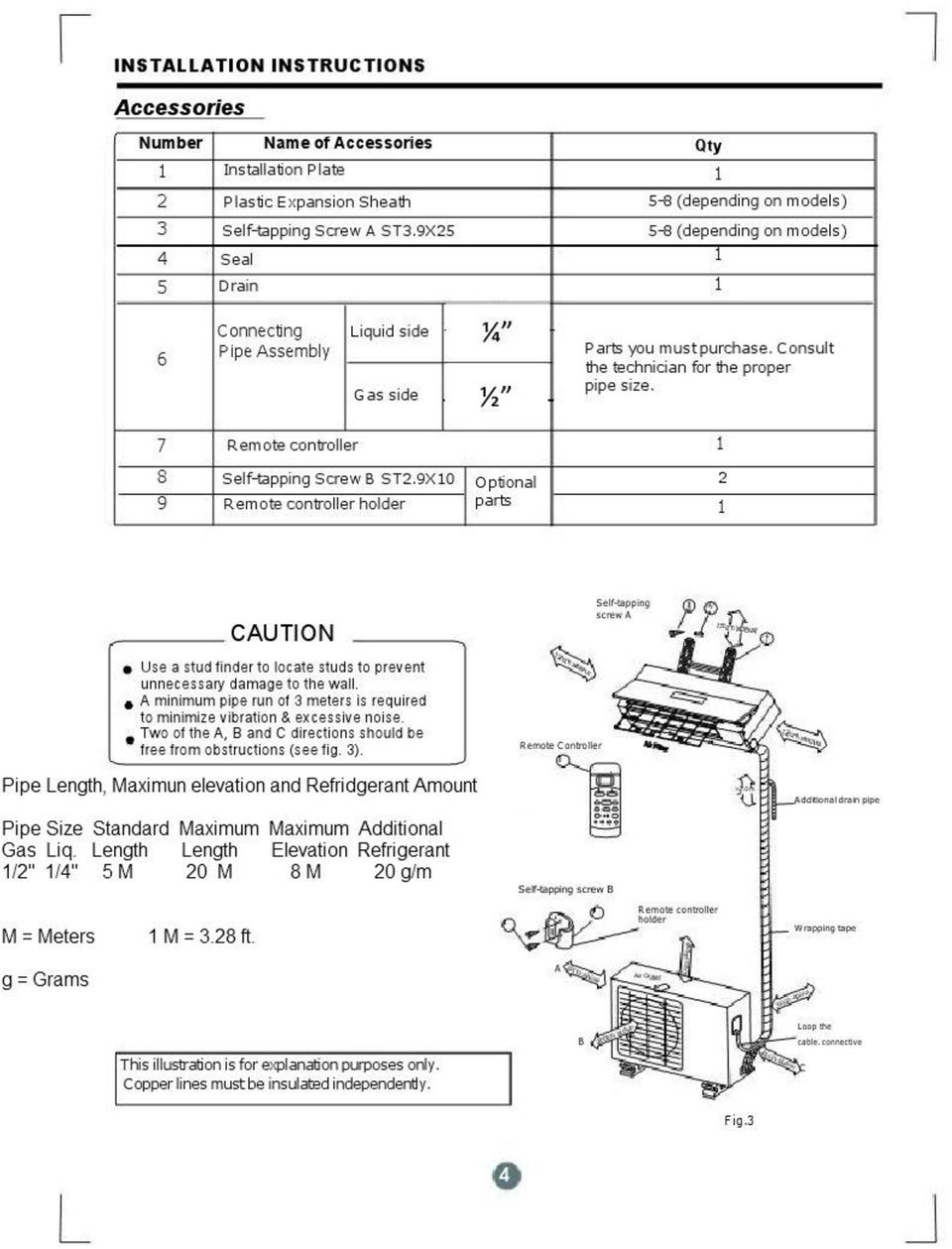
2 CONTENTS SAFETY PRECAUTIONS Warning 2 Caution 2 Selecting installation location 3 Accessories 4 Indoor unit installation 5 Outdoor unit installation 7 Refrigerant tube connection 8 Electrical work 9 Installation of the solar photovoltaic system 12 Wiring the MNPV3 21 Grounding Principals 22 2 Panel Grounding 23 3 panel Grounding 24 Safety and leakage check 24 Evacuation of line set 27 Testing 28 Please Print & Read This Manual Inside you will find many helpful hints on how to install and test the air conditioner properly. CAUTION Contact an authorized service technician for repair or maintenance of this unit. Only allow a qualified person to install this unit. The air conditioner is not intended for use by young children without supervision. Young children should be supervised to ensure that they do not play with the air conditioner. If the power cord is to be replaced, replacement work must be performed by authorized personnel only. Installation work must be performed in accordance with local building and electrical codes. 1

3 SAFETY PRECAUTIONS Read the follow SAFETY PRECAUTIONS carefully before installation. Electrical work must be installed by a licensed electrician. Be sure to use the correct rating and main circuit for the model to be installed. Incorrect installation may cause injury, death, or damage. Please pay attention to the following indications. WARNING CAUTION This symbol indicates the possibility of death or serious injury. This symbol indicates the possibility of injury or damage to property. The items to be followed are classified by the symbols: Symbol denotes item that is PROHIBITED 1) 2) WARNING Engage a properly trained person for installation. If installation is defective, you may experience water damage, electrical shock, or fire. Install according to these installation instructions. If installation is defective, you may experience water damage, electrical shock, or fire. 3) Use the included accessories and specified parts for installation. 4) Select a proper location for the indoor and outdoor unit make sure the location can support the weight of the unit. 5) For electrical work, follow the local electrical codes and these installation instructions. Use a dedicated circuit. If electrical circuit capacity or electrical work is not proper, it can cause electrical shock or fire. 6) Use the specified cable and connect tightly, clamping the cable so that the cable cannot come loose. A loose connection may cause sparks, overheating, fire, or damage the system. 7) Wiring routing must be properly arranged so that control board cover is fixed properly. If control board cover is not fixed properly, it will cause heat-up at connection point of terminal causing fire or electrical shock. 8) When installing the refrigerant tubing connection, make sure not to let any substances other than the specified refrigerant go into refrigeration tube. Otherwise, it may cause lower capacity, abnormally high pressure in the refrigeration cycle, explosion, or injury. 9) Do not modify the length of the power supply cord or use of extension cord, and do not share the circuit with other electrical appliances. CAUTION 1) This equipment must be installed with DC ground-fault protection (NEC 2005, Article 690.5) Refer to grounding section In this manual. 2) Do not install the unit in a location where leakage of flammable gas may occur. 3) Install drainage line described in the installation instructions. If drainage is not proper, water may accumulate and cause damage. 2 2
 2) WARNING Engage a properly trained person for installation.")
4 INSTALLATION INSTRUCTIONS Selecting installation location Select an installation location which is rigid and strong enough to support or hold the unit (21lbs), and select a location for easy maintenance. Read completely, then follow step by step. Indoor unit Do not expose the indoor unit to heat or steam. Select a place where there are no obstacles in front of or around the unit. Make sure that condensation drainage tube can be conveniently routed away. Do not install near a doorway. Ensure the spaces indicated by arrows from the wall, ceiling or other obstacles. A place where noise prevention is taken into consideration. Minimum 3 ft. from TV or electronic instrument. There should not be any direct sunlight on the indoor unit, sunlight may fade the color of the unit. More than 5 to the ceiling More than 4 More than 4 More than 77 from the floor Fig.1 Outdoor unit If an awning is built over the outdoor unit it must be done in a way that does not block air flow to the unit. More than 6 Keep the spaces indicated by arrows from wall or other obstacles. Do not place animals and plants in the path of the air inlet or outlet. Take the air conditioner weight (95 lbs) into account and select a place where noise, vibration, and hot air discharged will not be an issue. Do not install in a location exposed to flammable gas. Do not install high frequency machines such as a welding machine near the air conditioner. More than 11 Front More than 78 Fig.2 More than 23 Rooftop installation: If the outdoor unit is installed on a roof structure, be sure to level the unit. Ensure the roof structure and anchoring method are adequate for the unit location. Consult local codes regarding rooftop mounting. Recommended Tools For Installation: Level gauge Screwdriver Electric Drill Hole Saw Bit Flaring Tool Torque Wrench Adjustable Wrench Tape Measure Hex Wrench 4mm Leak Detector Vacuum pump Gauge manifold Users manual Thermometer Multi-meter Pipe Cutter 3

5
6 INSTALLATION INSTRUCTIONS Indoor unit installation 1. Fit the installation plate horizontally on structural parts of the wall with spaces around the installation plate. 2. If the wall is made of brick, concrete, or the like, use #8 anchor screws of the appropriate size. Correct orientation of Installation Plate Fig.4 3. Fit the installation plate on the wall with eight (8) anchor screws. Note: Fit the installation plate and drill holes in the wall according to the wall structure and corresponding mounting points on the installation plate. The installation plate is different according to the models. (Dimensions are in "mm" unless otherwise stated) 150mm or more to ceiling Indoor unit outline Installation plate 120mm or more to wall 120mm or more to wall Left rear side Right rear side refrigerant pipe hole Õ refrigerant pipe hole Õ Fig.5 Drill a hole in the wall 1. Determine hole positions according to the diagram detailed in Fig.5. Drill one (1) hole (2 ½ ) slanting slightly to outdoor side. 2. Always use wall hole conduit when drilling metal grid, metal plate, or the like. Indoor Wall Outdoor Fig.6 5

7 INSTALLATION INSTRUCTIONS Connective Tube and Drainage Installation 1. Run the drain hose sloping downward. Do not install the drain hose as illustrated in Fig When connecting extension drain hose, insulate the connecting part of extension drain hose with a shield pipe, do not let the drain hose slack. Do not block water flow by a rise. Fig.7 Do not put the end of drain hose into water. Right-hand piping Right rear piping Refrigerant Tube Installation IMPORTANT: The unit can only use right-hand piping or right rear piping as shown in Fig Remove the cover for right-hand piping first. 2. For the right rear piping, install the piping as shown in fig Fix the end of the connective pipe. (Refer to Tightening Connection in REFRIGERANT PIPING CONNECTION) Fig.8 Indoor unit installation 1. Pass the piping through the hole in the wall. 2. Put the upper claw at the back of the indoor unit on the upper hook of the installation plate, move the indoor unit from side to side to see that it is securely hooked (see Fig.9 & Fig.10). 3. Piping can easily be made by lifting the indoor unit with a cushioning material between the indoor unit and the wall. Remove material after it is not needed. 4. Push the lower part of the indoor unit up on the wall, then move the indoor unit from side to side, up and down to check if it is hooked securely. Upper Hook Lower Hook Fig.9 Fig.10 Cushioning material 6

8 INSTALLATION INSTRUCTIONS Piping and wrapping Bundle the tubing, connecting cable, and drain hose with tape securely, evenly as shown in Fig.11 Because the condensed water from rear of the indoor unit is collected in the drain pan to be piped out of room, do not put anything else in the drain pan. Indoor unit Connective cable Drain Pan Pipe room Drain hose CAUTION Connect the indoor unit first, then the outdoor unit. Do not allow the piping to drain out from the back of the indoor unit. Be careful not to let the drain hose slack. Make sure to insulate the tubing. Be sure that the drain hose is located at the lowest side of the bundle. Locating at the upper side can cause drain pan to overflow inside the unit. Never wrap the power wire along with control cable. Run the drain hose sloped downward to drain out the condensed water smoothly. Connective pipe Fig.11 Wrapping belt Outdoor Unit Installation Install the outdoor unit on a rigid base to prevent increasing noise level and vibration. Determine the air outlet direction where the discharged air is not blocked. In the case that the installation site is exposed to strong wind, make sure the fan is operating properly by putting the unit lengthwise along the wall or using a dust or shield plates. Especially in windy area, install the unit to prevent the admission of wind. If using a suspending installation, the installation bracket should Follow the technique required in the installation bracket diagram. The installation wall should be solid brick, concrete or the same intensity construction, or actions to reinforce, damping supporting should be taken. The connection between bracket and wall, bracket and the air conditioner should be firm, stable and reliable. Be sure there are no obstacles which block air flow. Strong wind Fig.12 7

9 REFRIGERANT TUBE CONNECTION Placement of outdoor unit Anchor the outdoor unit with bolts and nuts on a concrete or rigid mount Air inlet Air inlet Air outlet Drain Joint Installation If a drain elbow is used, the unit should be placed on a stand which is taller than 1.5. Fit the seal into the drain elbow, then insert the drain joint into the base pan hole of the outdoor unit, rotate 90 degrees to securely assemble. Connect the drain joint with the extension drain hose (locally purchased), to allow the water to drain from the outdoor unit during heating mode. Fig.13 Seal Drain joint Base pan hole of outdoor unit Refrigerant Tube Connection 1. Flaring work Main cause for refrigerant leakage is due to defect in the flaring work. Carry out correct flaring work using the following procedure: A: Cut the pipes and the cable. 1. Use the piping kit accessory or pipes purchased locally. 2. Measure the distance between the indoor and the outdoor unit. 3. Cut the pipes a little longer than the measured distance. 4. Cut the cable 60 longer than the pipe length. B: Burr removal 1. Completely remove all burrs from the cut cross section of pipe/tube. 2. Put the end of the copper tube/pipe in a downward direction as you remove burrs in order to avoid dropping burrs into the tubing. Fig.14 Seal Drain pipe 90 Oblique Roughness Burr Point down Pipe Fig.15 Reamer Fig.16 8

10 C: Putting Nut On Remove flare nuts attached to indoor and outdoor unit, then put them on pipe/tube having completed burr removal. (not possible to put them on after flaring work) D: Flaring Work Firmly hold copper pipe in a die in the dimension shown in the table below. Outer diam. A (mm)) (mm) Max. Min Tightening Connection Align the center of the pipes. Sufficiently tighten the flare nut with fingers, and then tighten it with a wrench and torque wrench as shown in Fig.20 & 21. Bar ELECTRICAL WORK Copper tube Copper pipe Flare nut Bar Clamp handle Fig.17 Fig.18 Outer Torque Additional Torque Diam. Indoor unit tubing Flare nut 1/ Ft. Lbs Ft. Lbs. Fig.19 Handle Yoke Cone Red arrow mark Tube 3/ Ft. Lbs Ft. Lbs. 1/ Ft. Lbs Ft. Lbs. Caution Excessive torque can break the nut.. Electrical Work Electric safety regulations for the initial Installation 1. If there is an unsafe power supply, the technician should refuse to install the air conditioner and explain to the client what the problem is. 2. Power voltage should be in the range of 90%~110% of rated voltage. 3. Ground Fault Protection must be provided, see page 22 for more details. Fig Ensure the air conditioner is grounded with a ground rod at the outdoor unit. 5. Refer to the Electrical Connection Diagram located on the panel of the outdoor unit to connect wires. 6. All wiring must comply with local and national electrical codes and be installed by licensed electricians. 7. An individual branch circuit and single receptacle used only for this air conditioner must be available. See the following table for suggested wire sizes and fuse specifications: 9

11 ELECTRICAL WORK Minimum nominal cross-sectional area of conductors: Rated current of appliance (A) Nominal cross-sectional area (mm) >3 and <6.75 >6 and <10 >10 and < >16 and < NOTE: The cable size and the current of the fuse or switch are determined by the maximum current indicated on the nameplate which is located on the side panel of the unit. Please refer to the nameplate before selecting the cable, fuse and disconnect. Fig.21 Fig.22 Back view of the front panel Connect the cable to the indoor unit NOTE: Before performing any electrical work, turn off the main power to the system. 1. The front panel should be removed before connecting the cable between inside and outside. 2. Push the front panel up straight, then open it to an angle of 20 degrees (Fig.21 & 22). To take down the front panel, you should first release the two lock levers on the back of the panel (Fig.23), Then lift it upward. Coupler plugs Lock lever Fig Release the coupler plugs connected with the front display panel as shown in Fig.24. Fig After taking down the front panel, remove the electrical box cover by loosening the screw as shown in Fig Connecting cable between indoor unit and outdoor unit shall be approved neoprene sheathed flexible cord, type designation H07RN-F or heavier cord. Ensure the color of wires of outdoor unit and the terminal Nos. are the same to the indoors respectively, Fig Wrap the cables not connected with terminals with insulation tape so that they will not touch any electrical components. Secure the cable onto the control board with the cord clamp. Connect the coupler plugs connected with the front display panel. Remove the front panel To remove the electrical box cover loosen the screw. Fig.25 10

12 ELECTRICAL WORK 7. Reinstall the electrical box cover, keep the white band just under the groove as shown in Fig. 26a and curve the cable into the groove. Make sure the cable connected with LED display window is fixed by the electrical box cover after installation, Fig.26b. Groove Connect the cable to the outdoor unit 1. Remove the electrical control board cover from the outdoor unit by loosening the screw as shown in Fig Connect the cables to the terminals as identified with their respective locations, see figure Secure the cable onto the control board with the cord clamp. 4. To prevent the ingress of water, form a loop of the connective cable as illustrated in the installation diagram of indoor and outdoor units. 5. Insulate unused cords (conductors) with PVC-tape, so they do not touch any electrical or metal parts. Cable connected with LED display window Band Fig.26a Terminals on the outdoor unit Y/G L1 L2 S L1 L2 L1 L2 To power supply S L1 L2 Y/G Terminals on the indoor unit Fig.27 Circuit Breaker OFF OFF To solar panel Fig.26b Cover Screw Fig.28 11

13 ELECTRICAL WORK Installation of the solar photovoltaic system This guide contains information regarding the installation and safe handling of solar photovoltaic module. All instructions should be read and understood before attempting to install. If there is any question, please contact our sales department for further explanation. The installer should conform to all the safety precautions listed in this guide when installing the module. Local codes should also be followed in such installations. This manual describes several typical systems of solar photovoltaic, but does not involve the specific structures and installation procedures of the installation. Please consult the supplier for the information of the following assemblies: a) the specifications of the solar photovoltaic system b) cable material c) connecting components d) bracket and support e) supporting parts Before installing a solar photovoltaic system, the installer should become familiar with the mechanical and electrical requirement for such a system. Keep this guide in a safe place for future reference (care and maintenance) and in case of sale or disposal of the module at the end of its useful life. General Installing solar photovoltaic systems may require specialized skills and knowledge. Installation should be performed only by qualified persons. All modules come with a permanently attached junction box and #12 AWG terminated in Multi-Contact PV-KBT4 (female) or PV-KST4 (male) connectors. The installer should assume the risk of all injury that might occur during installation, including without limitation, the risk of electric shock. The solar photovoltaic electrical energy production system must comply with the following table for suggested current and voltage specifications: Maximum Power Voltage (W) <700W Optimum operating voltage (Vmp) Optimum operating voltage (Vmp) Open-circuit voltage (Vmp) Short-circuit current (Vmp) Maximum power current (Pmax) <DC32V >DC20V <DC42V <DC25A <DC20A One individual module may generate DC voltages greater than 30 volts when exposed to direct sunlight. Contact with a DC voltage of 30V or more is potentially hazardous. Electrical joints such as the wire terminal will cause sparks, burning or deadly electric shock. Please do not touch such terminals directly under any circumstances. Fig.29 12

14 ELECTRICAL WORK When disconnecting wires from a photovoltaic module that is exposed to sunlight, an electric arc may result. Such arcs may cause burns, combustion and may otherwise create problems. Therefore, be extremely careful! Photovoltaic solar modules convert light energy to direct-current electrical energy. They are designed for outdoor use. Modules may be ground mounted, mounted on rooftops, vehicles, or boats. Proper design of support structures is the responsibility of the system designer and installer. Proper use of mounting holes is suggested in a following paragraph. Do not attempt to disassemble the module, and do not remove any attached nameplates or components. Fig.30 Do not apply paint or adhesive to module top surface. Do not use mirrors or other magnifiers to artificially concentrate sunlight on the module. Fig.31 When installing the system, abide with all local, regional and national statutory regulations. Obtain a building permit where necessary. Abide with any local and national regulations when mounting on vehicles or boats. Safety precaution for installing a solar photovoltaic system When installing the solar modules or repairing the air conditioner, ensure the circuit breaker on the solar panel of the outdoor unit is in the "OFF" state (push the switch to OFF position). OFF OFF ON ON Fig.32 13

15 Do NOT Connect in Series. It must be a Parallel connection.

16 ELECTRICAL WORK Only perform installation in dry conditions. Fig.38 Abide with the safety regulations for all other components used in the system, including wiring and cables, connectors, charging regulators, inverters, storage batteries and rechargeable batteries, etc. Use only equipment, connectors, wiring and support frames suitable for use in solar electric systems. Always use the same type of module within a particular photovoltaic system. The module frame must be properly grounded. The grounding wire must be properly fastened to the module frame to assure good electrical contact. Use the recommended type, or an equivalent, connector for this wire. Fig.39 Under normal outdoor conditions the module will produce current and voltages that are different than those listed in the data sheet. Data sheet values are values expected at standard test conditions. Accordingly, during system design, values of short-circuit current (Isc) and opencircuit voltage (Voc) marked on UL series modules should be multiplied by a factor of 1.25 when determining component voltage ratings, conductor amperage, fuse size and size of controls connected to the module or system output. The hole in the back of the module frame is used to drain the water, do not block it. Mechanical installation Select a suitable place for installation of the module. The module should not be shaded at any time of the day. The module should be facing due south in northern latitudes and due north in southern latitudes for best power production. For detailed information on the best elevation tilt angle for the installation, please consult with the solar photovoltaic system supplier. Do not use module near the place where flammable gas may be generated or collected. 15

17 ELECTRICAL WORK 2. Selecting the proper support frame Fig.40 Always observe the instructions and safety precautions included with the support frame to be used with the module. Never attempt to drill holes in the glass surface of the module, it will void the warranty. Do not drill additional mounting holes in the frame of the module, it will void the warranty. Fig.41 Modules must be securely attached to the mounting structure using four mounting points for normal installation. If additional wind or snow loads are considered for the installation, additional mounting points are also used. The support frame must be made of durable, corrosion-resistant and UV-resistant material. The heat expansion and cold contraction of the support frame should have no affect on its usage or performance. 3. Ground mount Select the height of the mounting system to prevent the lowest edge of the module from being covered by snow for a long time in winter in areas that experience heavy snowfalls. In addition, assure the lowest portion of the module is placed high enough so that it is not shaded by plants or trees or damaged by sand and stone driven by wind. Fig.42 16

18 4. Roof mount ELECTRICAL WORK When installing a module on a roof or building, ensure that it is securely fastened and cannot fall as a result of wind or snow loads. Fig.43 Provide adequate ventilation under a module for cooling (5cm minimum air space between module and mounting surface). Fig.44 When installing module on a roof, ensure that the roof construction is suitable. In addition, any roof penetration required to mount the module must be properly sealed to prevent leaks. In some cases, a special support frame may be necessary. The roof installation of solar modules may affect the fireproofing of the house construction, so it is necessary to use an earth ground fault circuit breaker. Any improper installation may cause accidental injuries. Fig.45 When installing the module on a roof or building, do so in calm winds. Installing a module during strong winds may cause accidents. 5. Pole mount When installing a module on a pole, choose a pole and module mounting structure that will withstand anticipated winds for the area. The pole must have a solid foundation. Roof mount Ground mount Pole mount Fig.46 17

19 ELECTRICAL WORK 6. General installation Module mounting must use the pre-drilled mounting holes in the frame. The most common mounting is achieved by mounting the module using the four symmetry points closed to the inner side on the module frame. If excessive wind or snow loads are expected, all eight mounting holes must be used. If you want to install the module without using the pre-drilled mounting holes in the frame, please consult with the supplier. Do not install in the rainy weather, it may cause insulation failure due to moisture, and there is a risk of electric shock. Fig.47 Do not attempt to lift the module by grasping the module's junction box while moving. Do not stand or step on module. Fig.48 Fig.49 Do not throw the module or drop any thing on the module. Fig.50 Do not place any heavy objects on the module. Do not set the module down hard on any surface. Do not scratch or break the glass. Fig.51 18

20 Extension cables will be needed in the 3 panel configuration connecting The J-Box cables to the combiner box. See figure 52a.

21 ELECTRICAL WORK Connection method B: Using 2 panels see Fig.52b. Outdoor unit wire connection Fig.52b If you want to connect the photovoltaic modules by using the cables purchased by yourself, the following requirements must be complied: Cable installation should comply with all local regional and national regulations. In some countries, an individual circuit breaker used between the solar panel and air conditioner must be installed. So select a circuit breaker in accordance with local regulations, and the rated current is more than 30A. The electrician must identify the positive pole and negative pole. Reverse connection may cause permanent damage to the air conditioner. Use qualified photovoltaic cables only. The cable can resist UV rays and climate of rapid change. The rated voltage of the cable is more than 600V. The cross section area of the cable depends on the maximum short circuit current and the length of wire. Be very careful when installing the cable at extremely low temperature. Recommended to use the cable of cross section area of 4mm or greater, and the wire should be as short as possible to reduce the energy consumption. When the modules are connected in parallel, cables must be securely fastened on the support frame which is used for mounting the modules to avoid wire slack. Fig.53 20
22 Wiring the MNPV3 21
23 GROUNDING PRINCIPALS Equipment grounding provides protection from shock caused by a ground fault and is required for all PV systems by the NEC. A ground fault occurs when a currentcarrying conductor comes into contact with the frame or chassis of an appliance or an electrical box. A person who touches the frame or chassis of the faulty appliance will complete the circuit an receive a shock. The frame or chassis is deliberately wired to a grounding electrode by an equipment grounding electrode conductor. The wire dose not normally carry current except in the event of a ground fault. The grounding conductor must be continuous, connecting every non- current carrying metal part of the installation to ground. It must bond or connect to every metal electrical box, equipment chassis, and photovoltaic panel mounting. The grounding wire is never fused, switched, or interrupted in any way. When metal conduit or armored cable is used, a separate equipment ground is not usually necessary since the conduit itself acts as the continuous conductor in lieu of the grounding wire. Grounding wires are still needed to connect appliance frames to the conduit. Ground-fault Protection Roof-mounted DC PV arrays located on dwellings must be provided with DC groundfault protection (NEC 2005, Article 690.5) Ground-fault protection isolates the grounded conductor (in DC, this is the negative wire) from ground under groundfault conditions. Size of Equipment Grounding Conductor The size of the equipment grounding wire can be as large as the current carrying conductors, both positive and negative wires, but not smaller than specified in NEC 2005, table
24 2 Panel Grounding Liquid Tight conduit may be used between the Standard AC Disconnect and the 30 AMP internal breaker in the Outdoor Unit. Max 6 ft. 23
25 3 Panel Grounding Liquid Tight conduit may be used between the Standard AC Disconnect and the 30 AMP internal breaker in the Outdoor Unit. Max 6 ft. 24
26 ELECTRICAL WORK Do not attach the cable on the sharp edge of the frames. Fig.54 Attention to the minimum bending radius of the wire. Fig.55 Do not unplug the connector when the power is on. Fig.56 The protecting sheath must be used on the cable if there is a possibility for animals or children to touch it. Fig.57 The manufacturer of the solar photovoltaic system can supply cables suitable for use in solar electric systems. 25
27 ELECTRICAL WORK If you want to use the connector purchased by yourself, the following requirements must be complied: Use only connector special designed for solar electric systems. Use the recommended or specified tools when install the connectors. Do not unplug the connectors when the power is on. The connector suitable for the solar photovoltaic system can be obtained from the manufacturer. Electrical connection: Completely cover the module with an opaque material during mechanical installation and electrical Installation. Protect the cables from being damaged. Ground mounting must abide with all local regulations. Storage battery can not be connected with the solar photovoltaic system. Grounding: The module frame must be properly grounded. The grounding wire must be properly fastened to the module frame to assure good electrical contact. If the support frame is made of metal, the surface of the frame must be electroplated and have excellent conductivity. The grounding wire must be properly fastened to the support frame. There are two pre-drilled mounting holes in the frame, used to install the grounding cable. Each module should connect with the grounding cable. We recommend the closed lug when grounding. First insert the ground cable into the jack of the closed lug, then insert the stainless steel bolt (M3) into the tab of the lug, the grounding hole on the frame and finally a nut to secure the entire assembly. The spring washer is required in order to prevent screw loosening and cause improper grounding. The grounding resistance must be less than 10 ohms. Fig.58 Junction box installation: All modules come with a permanently attached junction box and provide with fitted cables. The junction box is part of the panel itself, please contact the manufacturer if there is any problem with the module. Disclaimer of liability Because the use of this manual and the conditions or methods of installation, operation, use and maintenance of photovoltaic (PV) product are beyond our control, we do not take any responsibility and expressly disclaims liability for loss, damage, or expense arising out of or in any way connected with such installation, operation, use or maintenance. No responsibility is assumed by us for any infringement of patents or other rights of third parties, which may resulted by using the PV product. No license is granted by modification or otherwise under any patent or, patent rights. The information in this manual is based on company s knowledge and experience and is believed to be reliable; but such information including product specification (without limitations) and suggestions do not constitute a warranty, expressed or implied. We reserves the right to change the manual, the PV product, the specifications, or product data sheets without prior notice. 26
28 EVACUATION CAUTION After complying to the above conditions, prepare the wiring as follows: 1) Never fail to have an individual power circuit specifically for the air conditioner. As for the method of wiring, be guided by the circuit diagram posted on the inside of control cover. 2) The screws which fasten the wiring in the electrical box are liable to come loose from vibrations which the unit is subjected to during the course of transportation. Check them and make sure that they are all tightly fastened. (If they are loose, it could cause the wires to burn out.) 3) Specification of power source. 4) Confirm that electrical capacity is sufficient. 5) Check that the starting voltage is maintained at more than 90 percent of the rated voltage marked on the nameplate. 6) Confirm that the cable thickness is as specified in the power source specification. 7) Always install a GFI circuit breaker in a wet or moist area. 8) The following could cause a voltage drop: Vibration of a magnetic switch, which will damage the contact point. Also a bad fuse or breaker could cause a voltage drop. 9) The means for disconnection from a power supply shall be incorporated in the fixed wiring and have an air gap contact separation of at least 3mm in each active (phase) conductors. Evacuation Air and moisture in the refrigerant system have undesirable effects as indicated below: - Pressure in the system rises. - Operating current rises. - Cooling or heating efficiency drops. - Moisture in the refrigerant circuit may freeze and block capillary tubing. - Water may lead to corrosion of parts in the refrigeration system. The indoor unit and tubing between the indoor and outdoor unit must be leak tested and evacuated to remove any non-condensables and moisture from the system. Evacuation with vacuum pump - Preparation Check that each tube (both liquid and gas side tubes) between the indoor and outdoor units have been properly connected and all wiring for the test run has been completed. Remove the service valve caps from both the gas and the liquid side on the outdoor unit. Note that both the liquid and the gas side service valves on the outdoor unit are kept closed at this stage. - Pipe length and refrigerant amount: Line set pipe length Air purging method Additional amount of refrigerant to be charged Less than 16ft Use vacuum pump. Use vacuum More than 16ft pump. R410A: (Pipe length-5)x20g/m 27
29 EVACUATION When moving the unit to new location, perform evacuation using vacuum pump. Make sure the refrigerant added into the air conditioner is liquid form. Outdoor unit Refrigerant Indoor unit A Gas side C Liquid side D Caution in handling the packed valve Open the valve stem until it hits against the stopper. Do not try to open it further. Securely tighten the valve stem cap with a wrench. Valve stem cap tightening torque (See Tightening torque table in previous page ). When Using the Vacuum Pump (For method of using a manifold valve, refer to its operation manual.) 1. Completely tighten the flare nuts, A, B, C, D, connect the manifold valve charge hose to a charge port of the low-pressure valve on the gas pipe side. 2. Connect the charge hose connection to the vacuum pump. 3. Fully open the LOW valve of the manifold valve. 4. Operate the vacuum pump to evacuate. Check gauge for proper vacuum. 5. Run evacuation for 30 minutes or more and check that the vacuum meter indicates -76cmHg (-1x10⁵Pa). After the evacuation is complete, fully close the LOW valve of the manifold valve and stop the operation of the vacuum pump. 6. Turn the stem of the packed valve B about 45 degrees counter clockwise for 6~7 seconds to purge the line of air, then tighten the flare nut again. Make sure the pressure display in the pressure indicator is a little higher than the atmosphere pressure. 7. Remove the charge hose from the LOW pressure charge port. B Packed valve Fig.59 Flare nut Half union Stopper Cap Valve body Valve stem Fig.60 Manifold valve Compound meter Pressure gauge -76cmHg Handle Lo Charge hose Low pressure valve Fig.61 Handle Hi Charge hose Vacuum pump 8. Fully open the packed valve stems B and A. 9. Securely tighten the cap of the packed valve. 28
30 29
ROOM AIR CONDITIONER INSTALLATION MANUAL
 ROOM AIR CONDITIONER INSTALLATION MANUAL ( Split Type) Please read this installation manual completely before installing the product When the power cord is damaged, replacement work shall be performed
Installation Guide of Sunrise Solartech PV Modules. Term 2013. Contents. Purpose of this guide. General. Safety precaution for installing a solar
 Installation Guide of Sunrise Solartech PV Modules Term 2013 Contents Purpose of this guide General Safety precaution for installing a solar Photovoltaic system Product Identification Mechanical Installation
SPLIT -TYPE ROOM AIR CONDITIONER
 Before using your air conditioner, please read this manual carefully and keep it for future reference SPLIT -TYPE ROOM AIR CONDITIONER Please read this installation manual completely before installing
Split-type Air-Conditioner INSTALLATION MANUAL CONTENTS FOR INSTALLER MXZ-3A30NA MXZ-4A36NA ATTENTION. English. Français. Español
 Split-type Air-Conditioner MXZ-3A30NA MXZ-4A36NA INSTALLATION MANUAL Refer to the installation manual of each indoor unit for indoor unit installation. English Français Español ATTENTION This manual mentions
DC4812VRF Installation Guide
 DC4812VRF Installation Guide Version 1.4 Copyright 2013 HotSpot Energy 1 Notice To Owner/Installer This unit is designed for installation by an experienced person. It is legal for a homeowner to install
Room Air Conditioners
 Installation Manual Room Air Conditioners R410A Split Type Y Series DC INVERTER ECO940SD ECO1240SD ECO1840SD Please read this installation manual completely before installing the product. When the power
LG Floor Standing Type Air Conditioner INSTALLATION MANUAL
 website http://www.lgservice.com e-mail http://www.lgeservice.com/techsup.html LG Floor Standing Type Air Conditioner INSTALLATION MANUAL LG IMPORTANT Please read this installation manual completely before
CSUN Crystalline Silicon PV Module Products Installation Manual (IEC Version)
") CSUN Crystalline Silicon PV Module Products Installation Manual (IEC Version) ADD.:No.123, Focheng West Road, Jiangning Development Zone, Nanjing, China Code: 211100 TEL. : +86-25-52766666-6530/6728 FAX:
CSUN Crystalline Silicon PV Module Products Installation Manual (IEC Version) ADD.:No.123, Focheng West Road, Jiangning Development Zone, Nanjing, China Code: 211100 TEL. : +86-25-52766666-6530/6728 FAX:
BUILT-IN DISHWASHER INSTALLATION INSTRUCTIONS
 BUILT-IN DISHWASHER INSTALLATION INSTRUCTIONS PLEASE READ COMPLETE INSTRUCTIONS BEFORE YOU BEGIN LEAVE INSTALLATION INSTRUCTIONS AND USER'S GUIDE WITH OWNER ALL ELECTRIC WIRING AND PLUMBING MUST BE DONE
Installation Instructions
 READ BEFORE INSTALLING UNIT For Slider Casement Air Conditioners To avoid risk of personal injury, property damage, or product damage due to the weight of this device and sharp edges that may be exposed:
INSTALLATION INSTRUCTIONS Fan Coil Replacement Coil Kit EBX & EBXX
 Fan Coil Replacement Coil Kit EBX & EBXX These instructions must be read and understood completely before attempting installation. These instructions covers the installation of replacement coil kit into
Installation Instructions For Slider Casement Air Conditioners
 Installation Instructions For Slider Casement Air Conditioners NOTE: These instructions describe installation in a typical wood framed window with a wood SLIDE-BY sash, or installation in a metal CASEMENT
Reverse Cycle Inverter Split System Air Conditioner
 Reverse Cycle Inverter Split System Air Conditioner Model Number TAC-09CHSA/JAI5 INSTALLATION MANUAL Contents 03 Warranty Details 04 Welcome 05 General Safety Instructions 06 Product Overview 07 Selecting
SOLAR ELECTRIC MODULE ES-124 & ES-62T Owners Manual and Installation Guide
 SOLAR ELECTRIC MODULE ES-124 & ES-62T Owners Manual and Installation Guide circuit. Reverse connection will damage the module and may result in fire. CAUTIONS Solar electric modules produce DC electricity
Portable Air Conditioner
 Portable Air Conditioner Owner's Manual Model:3 in 1 12,000 Btu/h Series 3 Please read this owner s manual carefully before operation and retain it for future reference. CONTENTS 1. SUMMARY...1 2. PORTABLE
TECHNICAL DATA & SERVICE MANUAL SPLIT SYSTEM AIR CONDITIONER INDOOR UNIT: AW52AL AW64AL AW52AL 387030095 AW64AL 0.8180.463.0 07/05
 TECHNICAL DATA & SERVICE MANUAL INDOOR UNIT: AW52AL AW64AL SPLIT SYSTEM AIR CONDITIONER Model No. Product Code No. AW52AL 387030095 AW64AL 387030096 0.8180.463.0 07/05 IMPORTANT! Please read before installation
Ductless Split Air Conditioner
 Ductless Split Air Conditioner Installation Manual Indoor HSU09VHG(DB)-W HSU12VHG(DB)-W HSU18VHH(DB)-W HSU24VHG(DB)-W Outdoor HSU09VHG(DB)-G HSU12VHG(DB)-G HSU18VHH(DB)-G HSU24VHG(DB)-G Table of Contents
Cooktop Low-Profile Ventilation Hoods
 INSTALLATION GUIDE Cooktop Low-Profile Ventilation Hoods Contents Wolf Cooktop Low-Profile Ventilation Hoods........ 3 Cooktop Low-Profile Hood Specifications.......... 4 Cooktop Low-Profile Hood Installation............
INSTALLATION INSTRUCTIONS SINGLE SPLIT WALL MOUNTED AIR CONDITIONER
 INSTLLTION INSTRUCTIONS SINGLE SPLIT WLL MOUNTED IR CONDITIONER Please read this instruction sheet completely before installing the product. When the power cord is damaged, replacement work shall be performed
GENERAL INSTALLATION MANUAL FOR EGING PV MODULES
 GENERAL INSTALLATION MANUAL FOR EGING PV MODULES PLEASE READ THIS MANUAL CAREFULLY BEFORE INSTALLING OR USING THE MODULES. PLEASE PASS ALONG THE ATTACHED USER MANUAL TO YOUR CUSTOMER. 1. INTRODUCTION This
INSTALLATION INSTRUCTIONS
 INSTALLATION INSTRUCTIONS High Wall Mounted Ductless Split Type Air Conditioner WL-WT-WG-WH Series IDU Matched with AN-YN Series ODU WAL, WAT, WAH, WAG Cool Only WYL, WYT, WYH, WYG Heat Pump After-sales
How To Plan Out An Array Of Solar Panels
 CITY OF DOWNEY COMMUNITY DEVELOPMENT, BUILDING AND SAFETY 11111 Brookshire Avenue Downey, CA 90241 562.904.7142 (www.downeyca.org) B SECTION 01/01/2011 EFFECTIVE DATE PHOTOVOLTAIC 032 FORM NUMBER 2013
Inverter Room Air Conditioner Installation Manual KSV26CRE, KSV26HRE, KSV35CRE, KSV35HRE, KSV53HRE, KSV62HRE, KSV70CRE, KSV70HRE, KSV80HRE
 Inverter Room Air Conditioner Installation Manual KSV26CRE, KSV26HRE, KSV35CRE, KSV35HRE, KSV53HRE, KSV62HRE, KSV70CRE, KSV70HRE, KSV80HRE Refrigerant R32 Congratulations Contents Congratulations and thank
Air Conditioner Water Heater - A Product of HotSpot Energy LLC
 Air Conditioner Water Heater - A Product of HotSpot Energy LLC PLEASE READ THIS BEFORE YOU INSTALL THE UNIT 1. This air conditioner must be installed and/or repaired by a qualified technician. If you perform
Air Conditioner Water Heater Model ACWH18
 Air Conditioner Water Heater Model ACWH18 Installation Guide IMPORTANT! READ THIS FIRST! Commissioning of this unit must be done by a licensed HVAC technician. Commissioning includes making the electrical
ATS Overhead Table Shelf System INSTRUCTION MANUAL
 ATS Overhead Table Shelf System INSTRUCTION MANUAL ATS Overhead Table Shelf System Instruction Manual Warranty Newport Corporation warrants this product to be free of defects in material and workmanship
1. BEFORE INSTALLATION
 ENGLISH SPLIT-TYPE AIR CONDITIONERS INSTALLATION MANUAL JG79A191H03 MSZ-GE06/09/12/15/18NA MSY-GE09/12/15/18NA When installing multi units, refer to the installation manual of the multi unit for outdoor
IMPORTANT INSTRUCTIONS & OPERATING MANUAL. Houston 50 Inch Electric Wall Mounted Fireplace Black / White
 IMPORTANT INSTRUCTIONS & OPERATING MANUAL Houston 50 Inch Electric Wall Mounted Fireplace Black / White Model Number:MFE5050BK Model Number:MFE5050WH Read these instructions carefully before attempting
AIR-CONDITIONER SPLIT TYPE
 FILE NO. A08-016 SERVICE MANUAL AIR-CONDITIONER SPLIT TYPE RAS-M10PKVP-E, RAS-M13PKVP-E, RAS-M16PKVP-E, RAS-M18PKVP-E / RAS-M10PKVP-ND, RAS-M13PKVP-ND, RAS-M16PKVP-ND, RAS-M18PKVP-ND / RAS-3M26GAV-E1,
Floor Type Air-Conditioner INSTALLATION MANUAL CONTENTS FOR INSTALLER MFZ-KA25VA MFZ-KA35VA MFZ-KA50VA. English
 Floor Type Air-Conditioner MFZ-KA25VA MFZ-KA35VA MFZ-KA50VA INSTALLATION MANUAL This manual only describes the installation of indoor unit. When installing the outdoor unit, refer to the installation manual
Inverter Air Conditioner Installation Manual. KSV25CRF, KSV35CRF, KSV70CRF, KSV25HRF, KSV35HRF, KSV52HRF, KSV70HRF, KSV80HRF Refrigerant R32
 Inverter Air Conditioner Installation Manual KSV25CRF, KSV35CRF, KSV70CRF, KSV25HRF, KSV35HRF, KSV52HRF, KSV70HRF, KSV80HRF Refrigerant R32 Congratulations Contents Congratulations and thank you for choosing
What are the basic electrical safety issues and remedies in solar photovoltaic installations?
 What are the basic electrical safety issues and remedies in solar photovoltaic installations? Presented by: Behzad Eghtesady City of Los Angeles Department of Building and Safety Topics Covered Photovoltaic
MACBlower Model Number: MAC40R MAC60R MAC80R MAC100R. MAC120R MAC150R MAC 200R Serial # www.macblowers.com
 MACBlower Model Number: MAC40R MAC60R MAC80R MAC100R MAC120R MAC150R MAC 200R Serial # Fuji Clean USA 41-2 Greenwood Road Brunswick, Maine 04011 207-406-2729 www.macblowers.com MACBlowers The Intelligent
OWNER S MANUAL FORCE 10 MARINE COMPANY 23080 HAMILTON ROAD RICHMOND, BC CANADA V6V 1C9 TEL: (604) 522-0233 FAX: (604) 522-9608
 522-0233 FAX: (604) 522-9608") Electric Water Heater OWNER S MANUAL FORCE 10 MARINE COMPANY 23080 HAMILTON ROAD RICHMOND, BC CANADA V6V 1C9 TEL: (604) 522-0233 FAX: (604) 522-9608 If your water Heater is Damaged or you have questions
Electric Water Heater OWNER S MANUAL FORCE 10 MARINE COMPANY 23080 HAMILTON ROAD RICHMOND, BC CANADA V6V 1C9 TEL: (604) 522-0233 FAX: (604) 522-9608 If your water Heater is Damaged or you have questions
INSTALLATION AND OPERATING INSTRUCTIONS For Model GL1 Gate Locks
 Securitron Magnalock Corp. www.securitron.com ASSA ABLOY, the global leader Tel 800.624.5625 techsupport@securitron.com in door opening solutions INSTALLATION AND OPERATING INSTRUCTIONS For Model GL1 Gate
Infrarot-Bewegungsmelder IP44
 Infrarot-Bewegungsmelder IP44 infrared motion sensors IP44 ODA (weiß) slim ODA (schwarz) slim 95174 96000 ODA (weiß) ODA (schwarz) 95175 96001 Betriebsanleitung User s Manual User s Manual infrared motion
Solar Power Systems Models: PVS220W-24 and PVS220W-48 Installation Manual
 Solar Power Systems Models: PVS220W-24 and PVS220W-48 Installation Manual 255379 Rev. D0 1015 Printed in U.S.A. Copyright 2015 Federal Signal Corporation Limited Warranty The Alerting and Notification
AIR CONDITIONER INSTALLATION MANUAL
 FRANCAIS ESPAÑOL INSTALLATION MANUAL AIR CONDITIONER Please read this installation manual completely before installing the product. Installation work must be performed in accordance with the national wiring
RAY-MAX Integrated Solar Power Strip
 RAY-MAX Integrated Solar Power Strip 600008, 600009, 600010, 600208, 600209, 600210 Owner s Manual NEXTRONEX, INC. Revision Date: 10/27/14 Contents 1. Safety Instructions... 3 2. General Equipment Warnings...
SOLAR PV STANDARD ELECTRICAL PLAN Microinverter Systems for Single Family Dwellings
 *** Provide this document to the inspector along with ALL system installation instructions *** Project Address: Scope: Standard plan for the installation of grounded microinverter solar PV systems, not
Installation and Troubleshooting Instructions for Electric Tankless Residential Water Heaters.
 Model Number: Serial Number: Information Manual Installation and Troubleshooting Instructions for Electric Tankless Residential Water Heaters. ATTENTION: IF YOU ARE NOT A LICENSED PLUMBER OR A LICENSED
Packaged Terminal Air Conditioner Wall Sleeve Installation
 Installation & Maintenance Data IM 1196 Group: PTAC Part Number: 910141799 Date: October 2013 Packaged Terminal Air Conditioner Installation x 42" PGAN with Top-Mounted Hydronic Heat Note: Installation
Service manual. Website: www.andico.com.au CAUTION - BEFORE SERVICING THE UNIT, READ THE SAFETY - PRECAUTIONS IN THIS MANUAL.
 Website: www.andico.com.au Service manual CAUTION - BEFORE SERVICING THE UNIT, READ THE SAFETY - PRECAUTIONS IN THIS MANUAL. - ONLY FOR AUTHORISED SERVICE PERSONNEL. MODELS: MPK1-09CR-QB8 MPK1-12ER-QB6
OWNER S MANUAL DRAINVAC ATOMIK PRINTED APRIL 4-2011
 OWNER S MANUAL th DRAINVAC ATOMIK PRINTED APRIL 4-2011 INTRODUCTION We take this opportunity to express our gratitude and extend our congratulations for your decision to purchase a Drainvac product. A
LUCCI AIRFUSION QUEST II CEILING FAN
 LUCCI AIRFUSION QUEST II CEILING FAN WITH IR REMOTE INSTALLATION OPERATION MAINTENANCE WARRANTY INFORMATION CAUTION READ INSTRUCTIONS CAREFULLY FOR SAFE INSTALLATION AND FAN OPERATION. V1.0 QUEST II IR
CEILING CASSETTE TYPE AIR CONDITIONERS INSTALLATION INSTRUCTIONS
 CEILING CASSETTE TYPE AIR CONDITIONERS INSTALLATION INSTRUCTIONS Please read this instruction sheet completely before installing the product. When the power cord is damaged, replacement work should be
WARNING: FAILURE TO FOLLOW THESE RULES MAY RESULT IN SERIOUS PERSONAL INJURY CAUTION: INSTALLATION LOCATION:
 Revision Level: 01 Revision Date: 07/07/2011 Please read all instructions carefully to help ensure a correct and SAFE installation of your Second Wind Ultraviolet Germicidal Air Purifier. Failure to do
Wall Mounted Mini Split Heat Pump Air Conditioner
 Wall Mounted Mini Split Heat Pump Air Conditioner OPERATING AND INSTALLATION MANUAL Model: KFIHP-09-ID / KFHIP-09-OD KFHHP-12-ID / KFHHP-12-OD Indoor Unit. Outdoor Unit. Thank you for selecting Soleus
AIR CONDITIONER INSTALLATION MANUAL
 FRANCAIS ESPAÑOL INSTALLATION MANUAL AIR CONDITIONER Please read this installation manual completely before installing the product. Installation work must be performed in accordance with the national wiring
Installation Instructions for Alarm Module Kit A043F059
 Instruction Sheet 07-2013 Installation Instructions for Alarm Module Kit A043F059 1 Introduction The information contained within is based on information available at the time of going to print. In line
Ceiling Fan Installation Instructions
 Ceiling Fan Installation Instructions 1525..series OWNER S MANUAL READ AND SAVE THESE INSTRUCTIONS Total fan wieght with light kit 1-1525-CUL-English INSTALLATION CH-545 Safety Tips WARNING: TO REDUCE
UB1 AIR CONDITIONING UNIT INSTALLATION INSTRUCTIONS
 UB1 AIR CONDITIONING UNIT INSTALLATION INSTRUCTIONS INSTALLATION INSTRUCTIONS: Carefully read these instructions before installing your new air-conditioner. AUSTRALIAN AUTOMOTIVE AIR AL00500054E 1 Table
ALL WEATHER W-SERIES QUARTZ TUBE ELECTRIC INFRARED RADIANT HEATER INSTALLATION USE & CARE MANUAL
 ALL WEATHER W-SERIES QUARTZ TUBE ELECTRIC INFRARED RADIANT HEATER TABLE OF CONTENTS: INSTALLATION USE & CARE MANUAL IMPORTANT INFORMATION Assembly Instructions 2 Wiring Instructions 2 Outdoor Installation
aseries A13B Mini Bullet Camera User Manual
 aseries A13B Mini Bullet Camera User Manual Thank you for purchasing our product. If there are any questions, or requests, please do not hesitate to contact the dealer. This manual applies to the MicroView
2011/2008/2005 NATIONAL ELECTRICAL CODE SOLAR PV CODE COMPLIANCE REFERENCE
 2011/2008/2005 NATIONAL ELECTRICAL CODE SOLAR PV CODE COMPLIANCE REFERENCE PAGE 1 OF 5 This Reference provides a very comprehensive list of aspects of a solar PV installation that could be reviewed, clarifying
Roof Top Air Conditioner INSTALLATION AND OPERATING INSTRUCTIONS
 Roof Top Air Conditioner INSTALLATION AND OPERATING INSTRUCTIONS Ducted System RECORD THIS UNIT INFORMATION FOR FUTURE REFERENCE: Model Number: Serial Number: Date Purchased: This manual must be read and
CU-2E15LBE CU-2E18LBE CU-3E18LBE CU-4E23LBE
 Order No. PHAAM1003090C3 Outdoor Unit CU-2E15LBE CU-2E18LBE CU-3E18LBE CU-4E23LBE Air Conditioner Please file and use this manual together with the service manual for Model No. CS-E7LKEW CU-E7LKE CS-E7LKEW
SERVICE MANUAL. Room Air Conditioner Multi Split Wall-Mounted Type Indoor. FSAI-Pro-91AE2 FSAI-Pro-121AE2 FSAIF-Pro-181AE2
 SERVICE MANUAL Room Air Conditioner Multi Split Wall-Mounted Type Indoor FSAI-Pro-91AE2 FSAI-Pro-121AE2 FSAIF-Pro-181AE2 NOTE: Before servicing the unit, please read this at first. Always contact with
ELECTRICAL GUIDELINES FOR SINGLE-FAMILY HOME OWNERS:
 ELECTRICAL GUIDELINES FOR SINGLE-FAMILY HOME OWNERS: Chapter 12 of the Burlington Code of ordinances allows owner occupants of single family homes to do their own wiring if they choose. If you choose to
SPLIT TYPE ROOM AIR CONDITIONER INSTALLATION INSTRUCTION SHEET
 SPLIT TYPE ROOM AIR CONDITIONER INSTALLATION INSTRUCTION SHEET (PART NO. 97474700) For authorized service personnel only. This installation instruction sheet describes how to install the outdoor unit only.
PowerFlex 700S and 700H Frame 12 DC Bus Connector Kit
 PowerFlex 700S and 700H Frame 12 DC Bus Connector Kit Installation Instructions This document provides instructions for the installation of a DC bus connector kit for PowerFlex 700S and 700H frame 12 drives
DUCTED SPLIT TYPE AIR CONDITIONERS INSTALLATION INSTRUCTIONS
 LN-IM-01 DUCTED SPLIT TYPE AIR CONDITIONERS INSTALLATION INSTRUCTIONS Please read this instruction sheet completely before installing the product. When the power supply location is wanted to replace, replacement
Wiser Panel Meter, Model Number WISERCTPM200 Installer s Guide
 Instruction Bulletin EAV85226 08/2014 Wiser Panel Meter, Model Number WISERCTPM200 Installer s Guide Retain for future use. Product Description Kit Contents The Wiser Panel Meter is for use in energy management
Electrical Connection. Provide Proper Electrical Supply. Electrical Requirements. Connecting using the supplied cord and plug
 Electrical Connection When installed the range must be electrically grounded in accordance with local codes or; in the absence of local codes with the National Electrical Code ANSI/NFPA 70, latest edition.
INSTALLATION MANUAL ELECTRIC RANGE. Please read these instructions thoroughly before installing and operating the range.
 ENGLISH ESPAÑOL INSTALLATION MANUAL ELECTRIC RANGE Please read these instructions thoroughly before installing and operating the range. LRE3025ST LRE3085ST LRE3083ST LRE3083SB LRE3083SW LRE3021ST LDE3037ST
Elo Touch Solutions Wall-mounting Kit for the 5501L IDS Touchmonitors
 Installation Manual Elo Touch Solutions Wall-mounting Kit for the 5501L IDS Touchmonitors SW602206 Rev B Table of Contents Chapter 1: Safety Warning... 3 Chapter 2: Kit Contents... 4 Included in Kit...
3. SEISCO PARTS & SERVICE REMOVAL AND REPAIR GUIDE
 4 3. SEISCO PARTS & SERVICE REMOVAL AND REPAIR GUIDE A. Changing the Control Board B. Replacing a Heating Element C. Thermistor Replacement D. High Limit Switch Replacement E. Level Detector Replacement
Portable Air Conditioner. OWNER S MANUAL Read these instructions before use. Model: MM14CCS. Voltage rating: 115V~60Hz Power rating : 1400W
 Portable Air Conditioner OWNER S MANUAL Read these instructions before use Model: MM14CCS Customer Support : 1-800-474-2147 Voltage rating: 115V~60Hz Power rating : 1400W For product inquiries or support
HP switch LP switch Discharge thermo Comp. Surface thermo
 1 Specifications Zubadan Model Name PUHZ-SHW80VHA PUHZ-SHW11VHA PUHZ-SHW11YHA Power supply (phase, cycle, voltage) 1φ, V, Hz 1φ, V, Hz 3φ, 0V, Hz Max. current A 9.5 35.0 13.0 Breaker size A 3 16 Outer
16/32 Channel 1U Rack Mount CCTV Power Supply
 16/32 Channel 1U Rack Mount CCTV Power Supply Manual PH-A3224-GUQ Shown 16-Channel 32-Channel PTC PH-A1612-PUQ PH-A3224-PUQ Glass Fuse PH-A1612-GUQ PH-A3224-GUQ Industrial design 12 Amp 3 Amps per channel
Electrical Grounding. Appendix C
 Appendix C Electrical Grounding Low-Voltage Equipment Grounding The most frequently cited Office of Safety and Health Administration (OSHA) electrical violation is improper occupational grounding of equipment
INSTALLATION GUIDELINES for SOLAR PHOTOVOLTAIC SYSTEMS 1
 City of Cotati Building Division 201 W. Sierra Ave. Cotati, CA 94931 707 665-3637 Fax 792-4604 INSTALLATION GUIDELINES for SOLAR PHOTOVOLTAIC SYSTEMS 1 Any PV system on a new structures should be included
UHIR Series. Horizontal or Vertical Mounting Industrial / Commercial Electric Unit Heater. Owner s Manual
 UHIR Series Horizontal or Vertical Mounting Industrial / Commercial Electric Unit Heater Owner s Manual This manual covers installation, maintenance and repair parts. Read carefully before attempting to
Installation Instructions
 Installation Instructions Built-In Dishwasher If you have questions, call 1-800-4-MY-HOME (1-800-469-4663) or visit our website at: www.sears.com BEFORE YOU BEGIN Read these instructions completely and
OASIS-PLUS 120V READ ALL INSTRUCTIONS BEFORE OPERATING READ ALL INSTRUCTIONS BEFORE OPERATING OZONE IS A POWERFUL OXIDIZER AND MUST BE USED WITH CARE
 OASIS-PLUS 120V INFORMATION & OPERATING INSTRUCTIONS READ ALL INSTRUCTIONS BEFORE OPERATING READ ALL INSTRUCTIONS BEFORE OPERATING OZONE IS A POWERFUL OXIDIZER AND MUST BE USED WITH CARE 56041852 WARNING:
HP UPS R1500 Generation 3
 HP UPS R1500 Generation 3 Installation Instructions Part Number 650952-001 NOTE: The rating label on the device provides the class (A or B) of the equipment. Class B devices have a Federal Communications
Portable Air Conditioner. OWNER S MANUAL Read these instructions before use. Model: MN12CES / MN10CESWW
 Portable Air Conditioner OWNER S MANUAL Read these instructions before use 8 Model: MN12CES / MN10CESWW Voltage rating: 120V~60Hz Power rating : 1100W (MN12CES) Power rating : 900W (MN10CESWW) Customer
INSTALLATION INSTRUCTIONS FOR INTERNATIONAL 9000 SERIES ROOF TOP AIR CONDITIONERS
 RV Products Division INSTALLATION INSTRUCTIONS FOR INTERNATIONAL 9000 SERIES ROOF TOP AIR CONDITIONERS Service Contact: Coast to Coast RV Services Pty Ltd. 20 George Young St. Auburn NSW 2144 Australia
AIR CONDITIONER INSTALLATION MANUAL
 ENGLISH FRANÇAIS ESPAÑOL INSTALLATION MANUAL AIR CONDITIONER Please read this installation manual completely before installing the product. Installation work must be performed in accordance with the national
Arctic Leash Instruction Manual Alaskan Products Company LLC.
 Retractable Cord Reel for Engine Block Heaters Arctic Leash Instruction Manual Alaskan Products Company LLC. INSTALLATION INSTRUCTIONS This instruction manual is a reference guide for installing and operating
Requirements for Electrical Installations
 ARTICLE 110 Requirements for Electrical Installations INTRODUCTION TO ARTICLE 110 REQUIREMENTS FOR ELECTRICAL INSTALLATIONS Article 110 sets the stage for how you ll implement the rest of the NEC. This
Hi Wall Split Air Conditioners
 R22 220-240V ~, 50Hz Hi Wall Split Air Conditioners 53KHET 12-18-24 Cool Only 53QHET 12-18-24 Heat Pump INSTALLATION MANUAL Carrier is committed to continuously improving its products according to national
Arecont Vision H.264 Color or Day/Night SurroundVideo Series Installation Manual
 0 P a g e H.264 Color or Day/Night SurroundVideo Installation Manual Inside the box: A. Arecont Vision SurroundVideo camera B. Mounting template C. RJ45 female to female coupler D. Hex key E. Security
AMERBRITE UNDERWATER WHITE LED POOL LAMP
 AMERBRITE UNDERWATER WHITE LED POOL LAMP FOR USE ONLY WITH PENTAIR AMERLITE LUMINAIRE INSTALLATION AND USER S GUIDE IMPORTANT SAFETY INSTRUCTIONS READ AND FOLLOW ALL INSTRUCTIONS SAVE THESE INSTRUCTIONS
2010 Residential Water Heater Replacement Check List
 2010 Residential Water Heater Replacement Check List The intent of this check list is to provide installers a general reference for the enforcement of code requirements in the Greater San Diego Area. This
Owners & Installation Manual for the Sheridan, Mountainair, Pine Valley and Old Forge Ceiling Fan Family
 Owners & Installation Manual for the Sheridan, Mountainair, Pine Valley and Old Forge Ceiling Fan Family Part of the Kiva Lighting Family Custom Lighting and Fans Since 1992 1312 12th St NW Albuquerque,
MCR1900 Media Converter 19-Slot Chassis
 MCR1900 Media Converter 19-Slot Chassis Installation Guide Part #5500304-11 Copyright Statement This document must not be reproduced in any way whatsoever, either printed or electronically, without the
INSTALLATION AND OPERATIONS GUIDE FOR GRAND CANYON GAS LOG SYSTEMS
 INSTALLATION AND OPERATIONS GUIDE FOR GRAND CANYON GAS LOG SYSTEMS Installation and service must be provided by a qualified installer, service agency or gas supplier Grand Canyon Gas Logs, logs are made
Installer s Guide 18-AH39D1-13
 18-AH39D1-13 Cased Aluminum "Convertible" Coils 4TXCA018BC3HC** 4TXCA024BC3HC** 4TXCB025BC3HC** 4TXCB026BC3HC** 4TXCB031BC3HC** 4TXCB032BC3HC** ALL phases of this installation must comply with NATIONAL,
GreenWay Solar LED Path and Trail Lighting System. Installation and Owner s Manual
 GreenWay Solar LED Path and Trail Lighting System Installation and Owner s Manual Important Notes and Warnings This installation and instruction manual provides installation, operation, and maintenance
All work must conform to the National Electric Code, latest edition, and all other applicable codes and regulations.
 DIVISION 16 ELECTRICAL SECTION 16100 - ELECTRICAL PART 1 - GENERAL SCOPE All electrical work as shown on the drawings and as necessary to provide a complete electrical system. Include primary service,
Oil and Coolant Circulating Heating System. Model - OCSM
 Oil and Coolant Circulating Heating System Model - OCSM Installation & Operation Manual 216280-000 REV 2 Identifying Your System The HOTSTART heating system is designed to heat fluids for use in marine
INSTALL INSTRUCTIONS KK-C-HVAC-1 HVAC UNIT 2003-2014 CHEVROLET/GMC VANS FOR
 INSTALL INSTRUCTIONS KK-C-HVAC-1 HVAC UNIT 2003-2014 CHEVROLET/GMC VANS FOR (For NEW 2007 ALL WHITE KWIK-KITS ONLY) Warning do not attempt to install A/C units unless you are experienced with servicing
INFRARED QUARTZ WALL HEATER
 INFRARED QUARTZ WALL HEATER MODEL NO: IQ2000 PART NO: 6939004 MOUNTING & OPERATION INSTRUCTIONS GC0715 INTRODUCTION Thank you for purchasing this CLARKE Infrared Wall Heater. Before attempting to use this
YINGLI SOLAR PV MODULES Installation and User Manual
 YINGLI SOLAR PV MODULES Installation and User Manual Revision Date December 24, 2011 Applicable for IEC certified products This manual applies to photovoltaic modules ( PV modules, also commonly known
AIR CONDITIONER (SPLIT TYPE)
") INSTALLATION MANUAL AIR CONDITIONER (SPLIT TYPE) For general public use ENGLISH EN Indoor Unit RAS-07PKVP-E RAS-10PKVP-E RAS-13PKVP-E RAS-16PKVP-E RAS-18PKVP-E RAS-07PKVP-ND RAS-10PKVP-ND RAS-13PKVP-ND
INSTALLATION MANUAL AIR CONDITIONER (SPLIT TYPE) For general public use ENGLISH EN Indoor Unit RAS-07PKVP-E RAS-10PKVP-E RAS-13PKVP-E RAS-16PKVP-E RAS-18PKVP-E RAS-07PKVP-ND RAS-10PKVP-ND RAS-13PKVP-ND
PORTABLE AIR CONDITIONER
 PORTABLE AIR CONDITIONER MAC 7500 Owner s Manual Air Conditioner Dehumidifier Oscillating Fan Please read this owner s manual carefully before operating the unit. POWERED BY 66126113.p65 17 INTRODUCTION
NewAir AC-10100E / AC-10100H Portable Air Conditioner Owner s Manual PLEASE READ AND SAVE THESE INSTRUCTIONS
 NewAir AC-10100E / AC-10100H Portable Air Conditioner Owner s Manual PLEASE READ AND SAVE THESE INSTRUCTIONS ELECTRICAL SAFETY This appliance is for indoor use only. Always turn off the unit and unplug
CEILING CASSETTE TYPE AIR CONDITIONERS INSTALLATION INSTRUCTIONS
 CEILING CASSETTE TYPE AIR CONDITIONERS INSTALLATION INSTRUCTIONS (Refrigerant : R-407C) This unit is charged with new refrigerant, R-407C. Be sure to use proper tools for R-407C, when installing the unit.
CEILING CASSETTE FAN COIL UNIT
 CEILING CASSETTE FAN COIL UNIT Operation and Installation Manual MHCFC4W-04, 08, 12, 16 Four way ceiling cassette fan coil unit Please read this manual before using the fan coil unit. Installation and