Understanding the Cal Fire Solar Photovoltaic Installation Guideline
|
|
|
- Kellie Perry
- 8 years ago
- Views:
Transcription
1 Understanding the Cal Fire Solar Photovoltaic Installation Guideline Prepared for: Solar America Board for Codes and Standards (available soon at Brooks Engineering 873 Kells Circle Vacaville, CA Prepared by: Version 1.0 August 2010
 Brooks Engineering 873 Kells Circle Vacaville, CA 95688 www.")
2 BACKGROUND ON GUIDELINE DEVELOPMENT... 1 GUIDELINE LANGUAGE RECOMMENDATIONS FOR ENFORCEMENT MARKING (IFC ) Main Service Disconnect (IFC ) Marking Content and Format (IFC and ) Marking for dc Conduit, Raceways, Enclosures, Cable Assemblies, and Junction Boxes (IFC and ) Marking Content and Format (IFC and ) Inverters ACCESS, PATHWAYS AND SMOKE VENTILATION (IFC ) Residential Systems Single and Two Unit Residential Dwellings (IFC ) Access (IFC and ) Ventilation (IFC ) Commercial Buildings and Residential Housing Comprised of Three or More Units (IFC ) Access (IFC ) Pathways (IFC ) Ventilation (IFC ) LOCATION OF DC CONDUCTORS (IFC ) NON HABITABLE BUILDINGS (IFC ) GROUND MOUNTED PHOTOVOLTIAC ARRAYS (IFC ) INFORMATION INTENTIONALLY OMITTED FROM THE GUIDELINES New regulation under development for the IFC and UFC ii
... 8 2.2 Commercial Buildings and Residential Housing Comprised of Three or More Units (IFC 605.11.3.3)... 8 2.2.1 Access (IFC 605.11.3.3.1)... 8 2.2.2 Pathways (IFC 605.")
3 BACKGROUND ON GUIDELINE DEVELOPMENT INTRODUCTION NEED FOR A DOCUMENT TO EXPLAIN THE GUIDELINE The California Department of Forestry and Fire Protection (Cal Fire), Office of the State Fire Marshal released a document entitled Solar Photovoltaic Installation Guideline on April 22, This document was the culmination of over six months of meetings held in partnership with interested local fire officials, building officials, and solar industry representatives. The purpose of the document was to provide the photovoltaic (PV) industry with information on how to install systems in a way that meets the objectives of both the PV industry and the Fire Service. The guideline includes direction for three main areas: 1) Marking of Conduit and Equipment; 2) Access, Pathways, and Smoke Ventilation; and, 3) Location of Direct Current (DC) Conductors. Information is provided for the application of these areas for residential and commercial construction. Although specific information is provided on what measures should be adequate for compliance in these three areas, there is little information as to how these recommendations came to be, or what discussions preceded the development of the recommended requirements. The purpose of this document is to provide the reader with an understanding of how the California fire guidelines were developed and why they recommend that PV installations are installed with certain features to accommodate firefighters. While the guidelines do get specific about what is recommended, they do not provide explanation as to why the recommendations include the various provisions. While a regulation is under no obligation to explain itself, this SolarABCs document was developed to provide some background to help those who need to understand the guidelines. Several stakeholders are impacted by these guidelines and include fire prevention officers, plans reviewers, firefighters, building officials, PV system designers, PV system installers, and PV equipment manufacturers. In May of 2010, a revised version of the California fire guidelines was approved for inclusion into the 2012 version of International Fire Code. This raises the importance of the guidelines from a recommendation to a legally binding code. In the revised wording of the regulation, local fire jurisdictions are reminded of their prerogative to establish revised requirements that provide alternative means and methods of compliance. In general, approving an alternative method of compliance necessitates an in depth understanding of the original requirement. Without this background information it is more likely that local fire officials may be unwilling to entertain alternative means and methods and opt to rigidly implement the requirements. While many PV installations will have little trouble implementing the letter of the requirements, some installations may need adaptations negotiated with the fire department to make the installation feasible. A fire department that understands the purpose of the guidelines will be more likely to work with the PV system installation. Education of all stakeholders is the driving force behind this document. The purpose of the SolarABCs document is provide some of the background to the guideline so that those applying the guideline will be able to better understand the recommended requirements. This understanding is critical for the Fire Service and the PV industry so that any alternate means and methods that would be applied in the field has the benefit of some of the basic intent behind the guidelines. Without an understanding of intent, regulatory jurisdictions will feel obligated to enforce the letter of requirement without exception. This creates a process that lacks the flexibility that is often needed given the complexities of the built environment. The intention of Cal Fire, in working with the PV industry, was to develop the guidelines to facilitate the installation of PV systems in a way that addresses the Fire Service needs while not creating unnecessary obstacles. A better understanding of the lengthy deliberations that went into the 1
 industry with information on how to install systems in a way that meets the objectives of both the PV industry and the Fire Service.")
4 development of the guidelines will facilitate balanced and thoughtful enforcement as these guidelines become regulation. History of Guidelines In August of 2007, the California Office of the State Fire Marshal took on the task of developing guidelines for construction of PV systems in California that would address the concerns of firefighters. The task group was made up of representatives of the fire service, PV product manufacturers, PV contractors, experts from the fire and solar industries. Through to course of several meetings over a six month period, a set of guidelines were drafted that addressed 3 main areas: 1) identification of PV circuits, 2) access, pathways, and smoke ventilation, and 3) location of dc conductors. Future of Guidelines proposals for regulatory language There are two major fire codes used in the United States: 1) the International Fire Code (IFC) published by the International Code Council (ICC), and 2) the Uniform Fire Code (UFC) published by the National Fire Protection Association (NFPA). The UFC is also known by its code designation which is NFPA 1. The National Electrical Code (NEC ), which includes the fire safety requirements for electrical systems including PV systems is also published by NFPA and can be referred to by its code designation of NFPA 70. These codes, which together cover most of the United States, will be implementing provisions very similar to those in the California fire guidelines since they both used it as the template for their requirements. Initial Sections of Guideline Prior to the Guideline Language The California guidelines begins with several pages of introductory information including a history of the task force that developed the document, a short explanation of PV systems for stakeholders unfamiliar with the technology, a resource list for further study, and guidance on how the document should be implemented. The brief PV system background provides basic facts including that PV systems only produce electricity during daylight hours, where ac and dc disconnects are typically located, and that dc voltages can reach 600 volts. Different types of systems are listed including the fact that solar thermal systems for heating water or air may look similar to PV arrays but do not have the electrical hazards that PV systems have. GUIDELINE LANGUAGE RECOMMENDATIONS FOR ENFORCEMENT (Each section of the guideline includes the IFC reference for the corresponding section of the 2012 IFC that the language was placed into. The unenhanced text in the document is the description of the section, based on discussions in the PV Task Group meeting, and corresponding impact to PV system installation as these sections are enforced.) The following sections will cover each section of the guideline repeating the language from the guideline in italics, the IFC reference in parenthesis, and explanation in normal text. 1.0 MARKING (IFC ) Marking is needed to provide emergency responders with appropriate warning and guidance with respect to isolating the solar electric system. This can facilitate identifying energized electrical lines that connect the solar modules to the inverter, as these should not be cut when venting for smoke removal. 2
 identification of PV circuits, 2) access, pathways, and smoke")
5 Materials used for marking should be weather resistant. Use UL 969 as standard to weather rating (UL listing of markings is not required). The section on marking covers the requirements for identification of PV circuits and disconnecting means. The intent of the second paragraph related to weather resistance is to give some specific guidance on the fact that marking circuits and equipment in outdoor locations requires weather resistant products. UL 969 is a standard entitled, Marking and Labeling Systems and covers resistance of labeling materials to UV radiation and moisture. Common practice in the electrical industry is to have placards custom made by sign shops. These signs are often engraved plastic or metal materials. Generic vinyl signs are also available that printed in volume since the labels do not need to be customized. These vinyl signs should be specified as compliant with UL 969 while plastic and metal engraved signs would not require such a specification. 1.1 Main Service Disconnect (IFC ) For residential applications, the marking may be placed within the main service disconnect. If the main service disconnect is operable with the service panel closed, then the marking should be placed on the outside cover. For commercial application, the marking should be placed adjacent to the main service disconnect in a location clearly visible from the location where the lever is operated. This section is addressing the location and specifications for identifying that an electrical service includes a PV system. Since residential services often require opening a cover to access the main disconnect, the identification is required to be inside the cover so that emergency personnel clearly see the labeling while operating the main service disconnecting means. Sometimes this disconnecting means may be externally operable. In this case the sign would either need to be mounted on the equipment or adjacent to the equipment. The specifications for these signs indicate that adhesive fastened signs are acceptable, however, some jurisdictions require signs to be mechanically fastened. Mechanical fastening requirements often makes it difficult or impossible to mount the sign on outdoor equipment since putting fasteners in outdoor equipment may be a violation of the equipment listing. A mechanical fastening requirement will often require the sign to be mounted next to the equipment rather than on the equipment Marking Content and Format (IFC and ) MARKING CONTENT: CAUTION: SOLAR ELECTRIC SYSTEM RED BACKGROUND, WHITE LETTERING, MINIMUM 3/8 LETTER HEIGHT, ALL CAPITAL LETTERS, ARIAL OR SIMILAR FONT, NON BOLD, REFLECTIVE, WEATHER RESISTANT MATERIAL SUITABLE FOR THE ENVIRONMENT (durable adhesive materials meet this requirement) CAUTION: SOLAR ELECTRIC SYSTEM 3

6 1.2 Marking for dc Conduit, Raceways, Enclosures, Cable Assemblies, and Junction Boxes (IFC and ) Marking is required on all interior and exterior dc conduit, raceways, enclosures, cable assemblies, and junction boxes to alert the fire service to avoid cutting them. Marking should be placed on all interior and exterior dc conduit, raceways, enclosures, and cable assemblies, every 10 feet, at turns and above and/or below penetrations and all dc combiner and junction boxes. The dc side of the system requires identification according to the California guideline. Visual identification of different kinds of solar panels (electric and thermal) and equipment such as inverters, combiner boxes, disconnects, and wiring systems. With a basic understanding of these major components, along with the signs covered in this section, it should be clear to those fighting fires, or performing overhaul operations, that the equipment is present and a hazard exists during daylight hours. In commercial facilities, identification of the contents of piping systems, including electrical conduit, is common practice. These provisions are most suited to commercial applications. While there is no specific language exempting residential PV wiring systems from identifying these circuits, it is less necessary. Since residential wiring methods are dominated by non metallic cables, if the house has metal conduit installed, it is most likely either PV wiring or service entrance conductors both of which should be avoided. Simply said, commercial buildings have numerous metal piping systems, necessitating identification for several reasons while metal piping is less common in residential structures, reducing the need for such identification. In either case, firefighters should avoid touching these conduit. If a fire is present in the structure, these metal raceways may have compromised conductors inside that could energize the metal shocking those who might touch them Marking Content and Format (IFC and ) MARKING CONTENT: CAUTION SOLAR CIRCUIT (NEC and IFC uses Warning: Photovoltaic Power Source) RED BACKGROUND, WHITE LETTERING, MINIMUM 3/8 LETTER HEIGHT, ALL CAPITAL LETTERS, ARIAL OR SIMILAR FONT, NON BOLD, REFLECTIVE, WEATHER RESISTANT MATERIAL (durable adhesive materials meet this requirement) The requirements in this section are to standardize the information, size and color, and construction of the warning signs on wiring systems and junction boxes. Slight wording changes were made in the IFC proposal passed in May 2010 so that the wording in the IFC is consistent with the NEC. The message in the IFC proposal reads, Warning: Photovoltaic Power Source. 1.3 Inverters CAUTION SOLAR CIRCUIT The inverter is a device used to convert DC electricity from the solar system to AC electricity for use in the building s electrical system or the grid. 4
 and equipment such as inverters, combiner boxes, disconnects, and wiring systems.")
7 No markings are required for the inverter. 2.0 ACCESS, PATHWAYS AND SMOKE VENTILATION (IFC ) Section 2 of the guidelines only applies to fire departments that engage in vertical ventilation operations. While the majority of the fire service will engage in vertical ventilation operations, some departments are beginning to limit vertical ventilation based upon the type of construction of a structure, or the fire safety elements that the building includes. Some types of roof construction may not offer sufficient fire resistance to justify the risk of sending firefighters to the roof, while other buildings may have sufficient automatic vents making roof ventilation operations unnecessary. If manual roof ventilation is deemed unnecessary, the roof may only need access and egress for firefighting related to rooftop fires. Roof construction will also play a role in the decision process since non combustible roof decking such as concrete and metal may make ventilation or trenching operations impractical. While a few fire departments may engage in trenching operations on metal and concrete decked roofs, these departments are the exception rather than the rule. In general, exceptions to access pathways and smoke ventilation must be approved by the fire jurisdiction, so the specifics of construction and operations are intended to be handled through the design review process. Access and spacing requirements should be observed in order to: Ensure access to the roof Provide pathways to specific areas of the roof Provide for smoke ventilation opportunities area Provide emergency egress from the roof The introductory section of the access and smoke ventilation section outlines the purpose of this section. Since this section includes limiting locations for mounting PV modules, it is likely to be the focus of concern by those in the solar industry and in the fire service. Understanding the requirements in this section is critical to properly enforcing these rules and enabling flexibility to make adjustments to the rules when alternative means and methods can address the issues. The first list of bullets outlines why the requirements for clear spaces are needed for firefighters. The first bullet, Ensure access to the roof, refers to the need for fire fighters to gain access to the roof usually with ladders or similar means. Once access to the roof is achieved, then getting to specific areas on the roof that need inspection or ventilation is needed, which is stated in the second bullet. Another reason for spacing areas on rooftops is to provide a location where the roof can be ventilated to help remove smoke from inside a structure (bullet 3). Lastly, pathways are also necessary to quickly get off of a roof as bullet four suggests. Typically, multiple pathways for egress are identified while fighting a fire so that if the fire cuts off one egress pathway, an alternative can be used. The alternative pathways may not need to be as wide or structurally sound as the primary locations for access and egress. Local jurisdictions may create exceptions to this requirement where access, pathway or ventilation requirements are reduced due to: 5

8 Proximity and type of adjacent exposures Alternative access opportunities (as from adjoining roofs) Ground level access to the roof area in question Adequate ventilation opportunities beneath solar array (as with significantly elevated or widely spaced arrays) Adequate ventilation opportunities afforded by module set back from other rooftop equipment (shading or structural constraints may leave significant areas open for ventilation near HVAC equipment, for example.) Automatic ventilation device. New technology, methods, or other innovations that ensure adequate fire department access, pathways and ventilation opportunities. Designation of ridge, hip, and valley does not apply to roofs with 2 in 12 or less pitch. All roof dimensions measured to centerlines. Roof access points should be defined as an area that does not place ladders over openings (i.e., windows or doors) and are located at strong points of building construction and in locations where it does not conflict with overhead obstructions such as tree limbs, wires, or signs. The guidelines encourage local jurisdictions to have flexibility in the enforcement of these requirements due to a variety of site specific issues. The first three bullets describe examples of options that may allow fire departments to relax the setback options on a roof. PV arrays are often only mounted on one roof face (closest to south) so that other roof faces may be fully open to roof access and venting options. The next two bullets describe examples of PV array placement that allows for sufficient venting options due to the array being tilted above the roof pitch sufficiently to access the roof below the array or gaps in the array to reduce the shading affects of rooftop equipment such as HVAC units or shrouds hiding this equipment. The last two bullet items describe currently available ventilation options (automatic roof vents) and potential new innovations that may allow easy removal of PV modules for roof ventilation access. All of these measure can and should be taken into account when evaluating optional means and methods to meet the intent of adequate roof access and ventilation opportunities. 2.1 Residential Systems Single and Two Unit Residential Dwellings (IFC ) Plan review is required if a system is to be installed that will occupy more than 50% of the roof area of a residential building. Examples of these requirements appear at the end of this guideline. This statement is to delineate a relative system size where plan review is recommended. In order to achieve more than 50% of a residential roof are on a sloped roof typically means mounting PV modules on multiple roof faces. This complicates the installation and requires that the fire department review the plans to make sure that the PV system will still allow adequate access and ventilating opportunities. Systems that occupy less than 50% of a residence s roof area are simpler and are likely to have sufficient access and ventilation opportunities. This recommendation is not specifically mentioned in the IFC language. 6

9 2.1.1 Access (IFC and ) The 3 access and ventilation requirements in and are among the most controversial items in the guideline for both the solar industry and fire fighters. The origin of the 3 rule was a result of lengthy deliberation and debate. Initially, the fire service requested 4 setbacks while the solar industry preferred a 2 setback. A 3 setback was suggested that could reasonably address the access needs of the fire service while allowing more room for larger solar arrays to be installed. While the 3 setback may appear to be a simple compromise between 2 and 4, the origin is technically based. An issue not commonly understood in the solar industry is that wind loading on rooftops limits the available roof area on many homes in high wind regions. The American Society of Civil Engineers (ASCE) publishes a standard ASCE 7, entitled Building Loads on Structures, that is referenced by building codes in the U.S. This standard includes tables for wind pressures based upon location, wind exposure, and location on the roof. The outer 3 corners of a residential sloped roof structure has wind pressures that are double that of 3 in from the edge of the roof. Since PV modules are generally tested to withstand 30 PSF (pounds per square foot), areas of the country that have design wind speeds above 110 mph could experience wind pressures in excess of 30 PSF at roof corners. By staying away from the upper 3 corners of a sloped roof, PV modules can be mounted safely within their structural design capabilities while providing firefighters the access they need to get to the ridge of the roof for ventilation operations. The assumption in this section is that each roof face must stand on its own without relying on access from other roof faces. The reason for this distinction is that, during roof operations, adjacent roof faces may not be available for access or ventilation holes. One reason for a roof face to be unavailable for ventilation operations is that a strong wind could be impinging on that roof face making ventilation holes counterproductive. Single ridge roofs, such as full gable construction, has structurally strong framed end walls that provide good access and egress for the firefighter to either end of the structure. Hip roofs often have a relatively small center ridge section while providing side ridges (hips) to get to the corners of the building. Since these hips are not as structurally strong as the single ridge gable ends, only a single 3 pathway is required. This pathway is intended to be the primary access and egress for the roof. However, should this pathway be blocked or compromised during a fire since it is not as structurally strong as a gable end, firefighters would choose generally choose to make an emergency escape from the closest unaffected hip or slope to get to safety. (IFC ) a. Residential Buildings with hip roof layouts. Modules should be located in a manner that provides one (1) three foot (3 ) wide clear access pathway from the eave to the ridge on each roof slope where modules are located. The access pathway should be located at a structurally strong location on the building (such as a bearing wall.) Hip roofs only require one 3 pathway because it is necessary for at least one 3 pathway be available on any roof slope with a PV array. Although it is possible that a firefighter could walk on the opposing slope, there is a 3 pathway on the PV slope in the event a firefighter is having to rapidly cross the hip slope to access the ladder that may be against the PV slope at the corner. This would limit the total distance and time the firefighter would need to traverse the roof to get to a ladder. (IFC ) b. Residential Buildings with a single ridge. Modules should be located in a manner that provides two (2) three foot (3 ) wide access pathways from the eave to the ridge on each roof slope where modules are located. Single ridge residences require two, 3 wide pathways to provide alternate means of access and egress for firefighters during operations. As a related issue, these ridges can be long relative to the size of the structure so that there is a high likelihood that one pathway is inaccessible in a fire. 7

10 (IFC ) c. Hips and Valleys: Modules should be located no closer than one and one half (1.5) feet to a hip or a valley if modules are to be placed on both sides of a hip or valley. If the modules are to be located on only one side of a hip or valley that is of equal length then the modules may be placed directly adjacent to the hip or valley. Roof types covered in (a) and (b) are common simple roof constructions. However, many roofs cannot be described as simple hip or gable roofs but include a combination or ridges, valleys, and hips. Hips and valleys are treated differently from gable construction since the hips and valleys often do not have structural walls under them. This makes hips and valleys less substantial than other access and egress options and therefore a lower priority during firefighting operations. However, hips and valleys may become a path for emergency egress should a fire prevent the firefighter from accessing the preferred structural access and egress location Ventilation (IFC ) Modules should be located no higher than three feet (3) below the ridge. The purpose of the 3 ridge setback for residential sloped roofs is twofold. First, it provides for access along the ridge for firefighters to move along the structurally stronger ridge. A minimum of 18 on either side of the ridge is generally used for a pathway so that firefighters can work their way along a roof ridge and step aside to allow another firefighter to pass without them having to get too far away from the stronger ridge section. Second, the 3 space is intended to provide sufficient room for a standard 16 ft 2 vent hole to be cut 2 wide and 8 long. This 2 x 8 hole is in lieu of the more common 4 x 4 hole that is used for rafters or trusses on 24 centers. The 4 x 4 hole only requires a single hinging action with 24 rafter or truss construction, while a 2 x 8 hole requires additional cuts and at least two louvered sections. This method of venting is commonly referred to as Dicing. It allows for a scalable hole by just lengthening the top & bottom cuts and dicing in between, completing new louvered sections. 2.2 Commercial Buildings and Residential Housing Comprised of Three or More Units (IFC ) This classification covers all habitable structures that are not one and two family residences. The intention to follow building code classifications since there are numerous distinctions in building code between single and two family residences and other building types. Exception: If a local fire department determines that the roof configuration is similar to residential (such as in the case of townhouses, condominiums, or single family attached buildings), the local fire department may make a determination to apply the residential access and ventilation requirements. Examples of these requirements appear at the end of this guideline Access (IFC ) There should be a minimum six (6) foot wide clear perimeter around the edges of the roof. Exception: If either axis of the building is 250 feet or less, there should be a minimum four feet (4 ) wide clear perimeter around the edges of the roof. 8

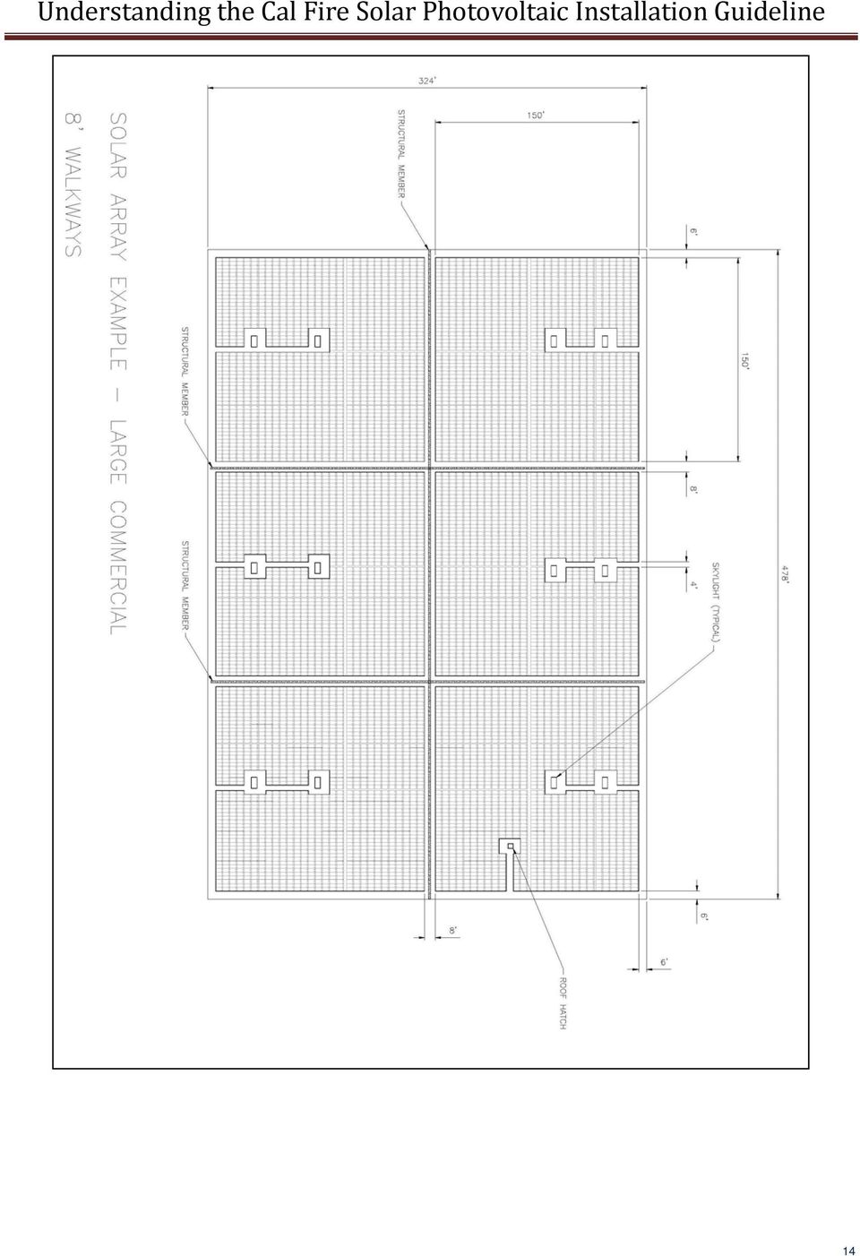
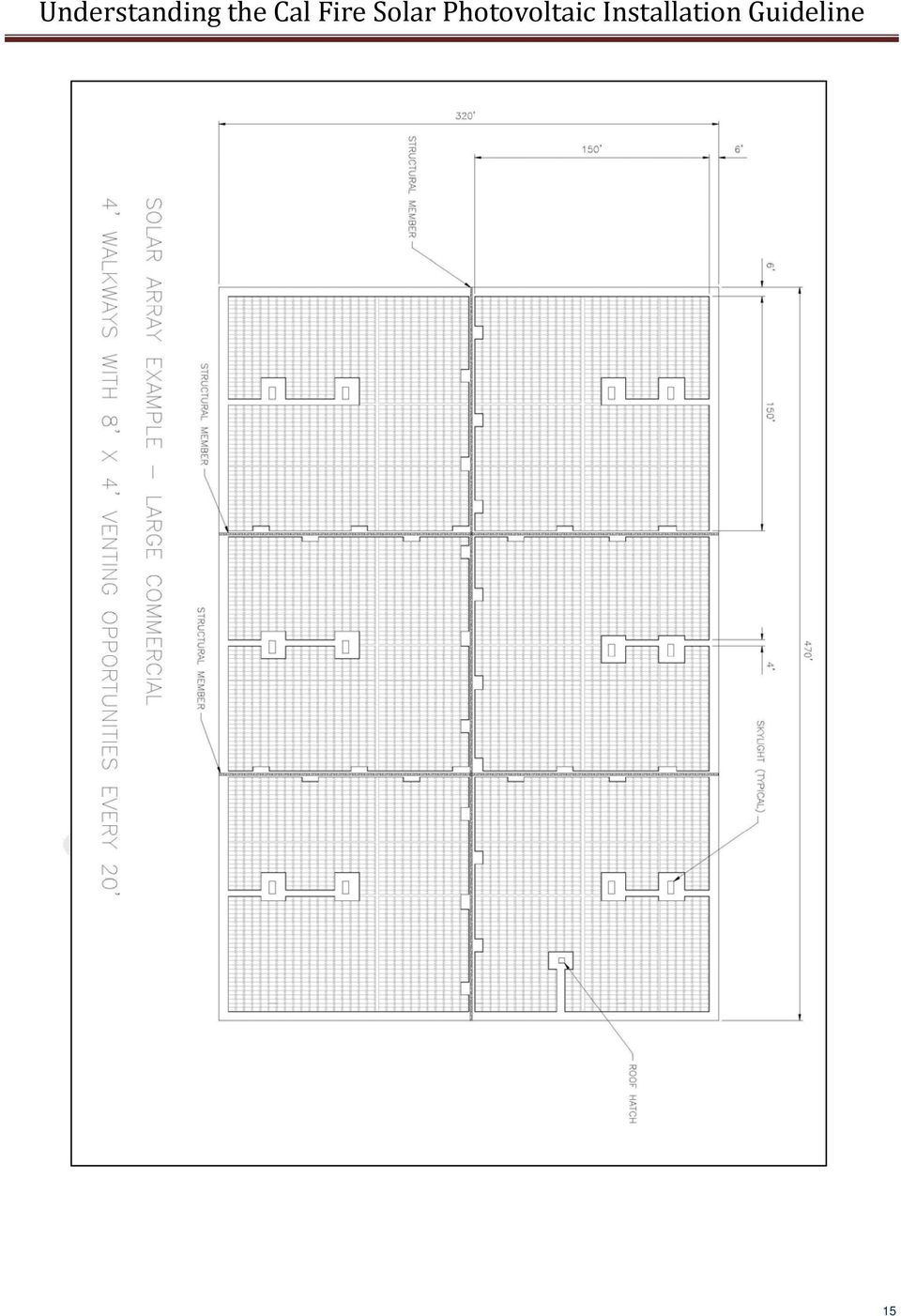
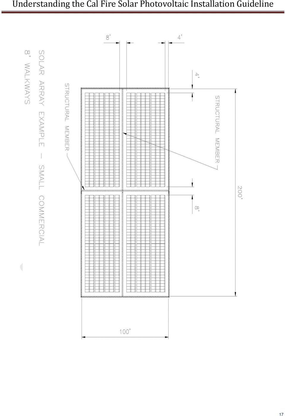
11 The access areas around the perimeter of a building are larger for commercial building than for single and two family residences for a variety of reasons. One reason is that the gear and equipment required for some roof operations on larger commercial buildings may be significant. Another reason is that more firefighters are generally dispatched for larger buildings, needing extra space for firefighters to maneuver around one another particularly in the vicinity of access ladders. The exception acknowledges the fact that smaller roofs will need less personnel and less clearance. For the solar industry, the perimeter area is often unusable due to two main reasons. First, shading from parapet walls on flat roofs can be significant. Generally, a setback distance of twice the parapet wall height is necessary to prevent excessive shading by the wall. A 3 high parapet wall will require a 6 setback to prevent shading. Second, higher wind speeds are associated with the perimeter of a roof making the edge of the roof unusable in many regions of the U.S. Lastly, the further the PV array is from the edge of a roof, the less likely construction workers will be exposed to edge of roof fall hazards Pathways (IFC ) Pathways should be established in the design of the solar installation. Pathways should meet the following requirements: a. Should be over structural members b. Center line axis pathways should be provided in both axis of the roof. Center line axis pathways should run on structural members or over the next closest structural member nearest to the center lines of the roof c. Should be straight line not less than 4 feet clear to skylights and/or ventilation hatches d. Should be straight line not less than 4 feet clear to roof standpipes e. Should provide not less than 4 feet clear around roof access hatch with at least one not less than 4 feet clear pathway to parapet or roof edge The pathway recommendations for commercial roofs are meant to place the walkways in locations most likely for firefighters would use during rooftop operations if no solar array were present. Generally, the firefighter will find a major structural member and follow that member across the roof when it is necessary to leave the roof edge. While following structural members is not always possible to do since the member may not be obvious, these provisions were intended to make those preferred paths available. Skylights, ventilation hatches, and standpipes are key ventilation and access locations that must have clear pathways from the edge of the roof, where the firefighter is free to move around the perimeter, to get to the ventilation location closest to the fire. Roof hatches may also be used for ventilation or building access depending on the source and type of the fire Ventilation (IFC ) a. Arrays should be no greater than 150 by 150 feet in distance in either axis b. Ventilation options between array sections should be either: 1. A pathway 8 feet or greater in width 2. 4 feet or greater in width pathway and bordering on existing roof skylights or ventilation hatches 3. 4 feet or greater in width pathway and bordering 4 x 8 venting cutouts every 20 feet on alternating sides of the pathway The reason the size of the array is discussed in the ventilation section is to allow for ventilation opportunities no further apart than 150. This assumes that a large building that could handle multiple 150 x150 array blocks is fairly open so that smoke can travel to an available venting location. The more compartmentalized the space 9

12 is below the roof, the more venting opportunities are preferred. Some buildings make ample use of skylights which can greatly help in providing venting opportunities for firefighters. Of course, these skylights and ventilation hatches need to be accessed with reasonable sized pathways. Maintenance personnel also need access to these locations to repair and maintain skylights and hatches. The third option is an attempt to allow for a 4 wide walkway and yet take up less room than an 8 pathway that would also be used for ventilation purposes. The alternating areas for ventilation are to provide venting options on either side of a structural member in case that structural member is over a partition wall. While this option helps meet the needs of the fire service, alternating sides of the pathway would not be a preferred method for the effective layout of a PV array so it is less likely to be used by PV system designers. 3.0 LOCATION OF DC CONDUCTORS (IFC ) Conduit, wiring systems, and raceways for photovoltaic circuits should be located as close as possible to the ridge or hip or valley and from the hip or valley as directly as possible to an outside wall to reduce trip hazards and maximize ventilation opportunities. Conduit runs between sub arrays and to DC combiner boxes should use design guidelines that minimize total amount of conduit on the roof by taking the shortest path from the array to the DC combiner box. The DC combiner boxes are to be located such that conduit runs are minimized in the pathways between arrays. To limit the hazard of cutting live conduit in venting operations, DC wiring should be run in metallic conduit or raceways when located within enclosed spaces in a building and should be run, to the maximum extent possible, along the bottom of load bearing members. Since the development of these guidelines in early 2008, several additions have been made to the 2011 National Electrical Code (NEC ) to address concern of firefighters in the routing of conductors. In the majority of residential rooftop systems, conduit is run exterior to the structure. Conduit runs generally proceed from the edge of the array closest to the location of the inverter, and the shortest possible path is taken to get to the inverter. Ridges, hips and valleys may be used to run conduit as recommended in this section. If conduit is run inside the structure, this is typically done in attic spaces so the last paragraph makes the statement to run the conduit along the bottom of load bearing members to the extent possible. The purpose behind this recommendation is that since firefighters are not going to cut through load bearing members, this would be a safer location to route conduit. However, other options may be as good or better in reducing the likelihood of conduit damage from firefighter operations. A series of requirements adopted by the 2011 NEC more specifically clarify the acceptable options. These sections are shown here for reference (E) (E) Circuit Routing. Photovoltaic source and PV output conductors, in and out of conduit, and inside of a building or structure, shall be routed along building structural members such as beams, rafters, trusses, and columns where the location of those structural members can be determined by observation. Where circuits are imbedded in built up, laminate, or membrane roofing materials in roof areas not covered by PV modules and associated equipment, the location of circuits shall be clearly marked (E) (New) Wiring methods shall not be installed within 25 cm (10 in.) of the roof decking or sheathing except where directly below the roof surface covered by PV modules and associated equipment. Circuits shall be run vertically from the roof penetration point to supports a minimum of 25 cm (10 in.) below the roof decking. 10

13 Informational Note: The 25 cm (10 in.) requirement is to prevent accidental damage from saws used by firefighters for roof ventilation during a structure fire. Where flexible metal conduit (FMC) or metal clad cable (MC) smaller than metric designator 21 (trade size 3 4) containing PV power circuit conductors is installed across ceilings or floor joists, the raceway or cable shall be protected by substantial guard strips that are at least as high as the raceway or cable. Where run exposed, other than within 1.8 m (6 ft) of their connection to equipment, these wiring methods shall closely follow the building surface or be protected from physical damage by an approved means: 4.0 NON HABITABLE BUILDINGS (IFC ) This guideline does not apply to non habitable structures. Examples of non habitable structures include, but are not limited to, parking shade structures, solar trellises, etc. 5.0 GROUND MOUNTED PHOTOVOLTIAC ARRAYS (IFC ) Setback requirements do not apply to ground mounted, free standing photovoltaic arrays. A clear brush area of 10 is required for ground mounted photovoltaic arrays. Clear brush areas are required around ground mounted systems to reduce the safety hazard of fuel from brush that could start a fire that would propagate beyond the limits of the PV array. Examples of Compliant PV Array Layout for Different Rooftops (shown on following pages) Example 1 Cross Gable Roof Example 2 Cross Gable With Valley Example 3 Full Gable Example 4 Full Hip Roof Example 5 Large Commercial 8 Walkways Example 6 Large Commercial 4 Walkways Example 7 Small Commercial 4 Walkways Example 8 Small Commercial 8 Walkways 11
 of their connection to equipment, these wiring methods shall closely follow the building surface or be protected from physical damage by an approved means: 4.")
14 Diagram 1: Cross Gable Roof Diagram 2: Cross Gable with Valley 12

15 Diagram 3: Full Gable Example 4: Full Hip Roof 13

16 14
17 15
18 16

19 17
20 INFORMATION INTENTIONALLY OMITTED FROM THE GUIDELINES PV ARRAY DC DISCONNECTS TO PROTECT FIREFIGHTERS As members of the Fire Service have been tasked with developing installation guidelines for PV systems in the past decade, one of the most common requirements that are drafted relates to disconnects on rooftops. The assumption is that adding disconnects at the source of power, the PV array, will effectively eliminate that source from the building. The history of service disconnects for fire operations is to protect fire fighters from energized conductors. One of the first activities of a team of fire fighters is to control the energy utilities to a structure (typically utility electrical and gas). The addition of a PV system on the roof of the structure poses a unique challenge to fire fighter operations. Unfortunately, given the design and layout of a rooftop PV system, opening a disconnect may not de energize any of the circuits associated with the switch. The reasons for this will be covered later in this document. If the circuits are not de energized, and a firefighter believes that it is safe to move a raceway associated with that switch, it is possible that the firefighter could be severely shocked or electrocuted. For this reason, the California Fire Service s, Draft Solar Photovoltaic Installation Guideline, dated April of 2008 does not include any language related to rooftop PV array switches. The guidelines also do not state why such a requirement was omitted. This has caused various jurisdictional authorities and fire enforcement representatives to believe that the omission was accidental and proceed to introduce an additional requirement. PROPOSED LANGUAGE FOR IFC F Power disconnects. A power disconnect shall be located within 3 feet of the photovoltaic array to provide for de energizing the DC circuit(s) from the array to the inverter. The disconnect shall be labeled with reflective lettering. THE PROBLEM As stated in the introduction, opening a rooftop dc disconnect in a PV system does not de energize the conductors on either side of the switch. Because of this concern, the National Electrical Code (NEC), published by the National Fire Protection Association as standard NFPA 70, requires a warning sign on these types of switches. This sign must read substantially WARNING. ELECTRIC SHOCK HAZARD. DO NOT TOUCH TERMINALS. TERMINALS ON BOTH THE LINE AND LOAD SIDES MAY BE ENERGIZED IN THE OPEN POSITION. 18

21 This warning is primarily for electricians performing work on the equipment as a reminder that normal electrical conventions do not hold for this equipment. Normally, a safety disconnect has energized conductors to the line side of the switch, but the load side of the switch is always de energized when the switch is open. This is due to the fact that no other source of power typically exists on the load side of a switch. With PV systems, this assumption is wrong in almost every case, thus the requirement for a warning sign. To understand why the load side of a dc switch in a PV array is typically energized, we must look at how PV systems work, and the common equipment that is used. The majority of rooftop PV systems are connected directly to an electrical converter, called an inverter, that takes the dc power from the PV array, turns it into ac power compatible with the utility system, and then supplies that power to existing distribution equipment in the building. On the ac side, if the utility power is shut down for any reason, the ac output of the PV system inverter instantly shuts down to prevent a hazardous condition on the ac wiring in the building or local utility. If the ac side is shut down, the dc power from the array instantly stops flowing. The dc current stops, but the dc voltage remains the PV array sits in an open circuit condition awaiting the return of utility power. This open circuit condition, while not flowing power, is none the less hazardous to anyone coming in contact with the circuits. That is the fundamental reason the fire service logically wants to shut the voltage off in that circuit. In small, residential rooftop PV systems, all the circuits from the roof are typically run into a single raceway so it seems logical to install a dc disconnect to de energize this conduit. Although it is possible to interrupt the circuit from the roof to the inverter, the voltage on the load side of the switch is coming from the inverter. This voltage comes from an additional source in the inverter that source is the input capacitors for the array. All PV inverters without battery systems include large input capacitors. The purpose of these input capacitors is to store half wave power from the PV array so that the inverter can produce ac power, which fluctuates at 60 cycles, and keep the power from the PV array at a constant dc voltage (INSERT DIAGRAM SHOWING DC AND AC POWER). These capacitors have bleed resistors attached to them to gradually deplete the charge to zero volts when the voltage is removed from them. This bleed down process takes 5 to 15 minutes and is intended to make the equipment safe for servicing. This 5 to 15 minute time period is fine for maintenance work, but far too long for fire operations. A firefighter, thinking this circuit is de energized, could easily be shocked by these large capacitors. While the shock on a small PV system is unlikely to be fatal, the involuntary muscle reaction to the shock could easily cause the fire fighter to lose balance and fall off the roof resulting in serious injury or fatality. On larger commercial PV systems, there can be dozens of electrical distribution boxes all electrically combined at a large inverter at ground level. Although the 2011 NEC will require dc disconnects for each rooftop combiner box, turning off any one of these disconnects, or all the disconnects, may not de energize any of the circuits or conduit. For the same reason small systems are not de energized, large inverters have massive capacitor banks that are capable of delivering a severe burn or even electrocution. These capacitor banks have bleed resistors, but the same 5 to 15 minute waiting period exists for big inverters just like small inverters. The capacitors will only start to discharge after all the rooftop disconnects are opened. 19
22 IMPACT ON FIRE OPERATIONS The typical protection that a disconnecting means provides with utility ac services does not exist with dc disconnects in a PV system. The conventional ac frame of reference used by an electrician or a firefighter while doing their job is dangerous and potentially fatal. Thus the code requirement for warning signs on all these disconnects. For example, if 15 disconnects exist on the roof, one at the location of each subarray combiner box, only one of the 15 need to stay on in order for the entire array wiring system to stay fully energized and lethal. In the smoke and confusion during a fire, it is too likely that one or more of these disconnects will not be identifiable or accessible because fire is blocking access. Firefighters in daytime operations need to work from the assumption that the equipment is energized and potentially dangerous. The 2011 NEC has established several new requirements for PV systems in routing of wiring systems, marking, arc fault detection systems, and disconnects for combiner boxes. These improvements in safety will not solve all current hazards, but they will reduce the hazard to firefighters and maintenance personnel. Basic education on the hazards of PV systems is the key to effective fire fighting operations. While disconnects on combiner boxes will help isolate circuits during overhaul operations, they should not be the focus during fire suppression operations. Simply staying clear of PV modules and the associated raceways is the only way to guaranty the safety of the fire fighter. Requiring disconnects, from a fire safety point of view, should be carefully considered in light of the misunderstandings and potential injury these misunderstandings will ultimately result in. TECHNOLOGY ADVANCES THAT MAKE PV SYSTEMS SAFER While current PV system design does not favor the use of dc disconnects to provide protection for firefighters, several new technologies show promise of addressing some or all of the major electrical concerns of the firefighter. These new technologies place communications and control features directly into each module, allowing individual modules to shut down instantly if necessary. These module level electronics, sometimes called Module Level Control or Smart Modules, could easily communicate with the inverter and shut each module off in the event of a utility outage or the opening of the main ac service disconnect. By controlling the voltage at the module level, the electrical hazards of the PV array are removed allowing the firefighter to concentrate on their main goal of fire suppression rather than energy control for the PV system. 20
23 New regulation under development for the IFC and UFC There are two primary fire codes used in the U.S. today. The first is the International Fire Code (IFC) published every 3 years by the International Code Council (ICC). The second is the Uniform Fire Code (UFC) published by the National Fire Protection Association (NFPA). The UFC is often referred by the code designation of NFPA 1. Both draft documents for the 2012 code cycle include language related to solar photovoltaic system regulation that is based upon the California guideline. One significant difference between the California document and these fire regulations is the emphasis of the language. Since the California document is a recommended practice, and not a requirement, words like must and shall cannot be used. However, since the IFC and UFC are standards written as requirements, the word shall is used in place of should. The IFC F30 Code compared to the California Guideline This section will outline the significant differences between the IFC F30 requirements and the California Guideline. As of the initial draft of this document, it was unclear what language would be adopted by the UFC so that comparison will wait for a future version of this report. Setting the two documents side by side it becomes clear that the IFC regulation is largely based upon the California document with the increased emphasis of code requirements. However, several important differences do exist. Rather than cover all the similarities, only the significant differences will be addressed in this section. The reasoning behind issues such as access, pathways, and ventilation have not been changed, but the reasons for the different language will be discussed in the context of rest of this explanation document. To summarize the differences up front, the following list is provided. 1. All instances of should were removed and changed to shall as appropriate to make the statements code requirements rather than recommendations. 2. The recommendation to have access pathways on top of structural members of building is amended to require only that the roof be capable of handling the live load of a firefighter. 3. The exception for the option for fire departments to amend the 3 rule for residences is prominently featured at the beginning of the section on access, pathways, and smoke ventilation. 4. The National Electrical Code is referenced for additional requirements for marking, labeling, and routing of wiring methods. 5. Ladder access is specified so that the locations are not in front of windows or doors, and the access points do not conflict with obstructions such as tree limbs, wires, or signs. New Language for the 2012 IFC: Solar Photovoltaic Power Systems. Solar photovoltaic power systems shall be installed in accordance with this code, the International Building Code and NFPA
24 Exception: Detached Group U non habitable structures such as parking shade structures, carports, solar trellises, and similar type structures are not subject to the requirements of this section Marking Marking is required on all interior and exterior dc conduit, enclosures, raceways, cable assemblies, junction boxes, combiner boxes, and disconnects Materials. The materials used for marking shall be reflective, weather resistant and suitable for the environment. Marking as required in sections through shall have all letters capitalized with a minimum height of 3/8 inch (9.5 mm) white on red background Marking content. The marking shall contain the words WARNING: PHOTOVOLTAIC POWER SOURCE Main service disconnect The marking shall be placed adjacent to the main service disconnect in a location clearly visible from the location where the disconnect is operated Location of Marking. Marking shall be placed on all interior and exterior dc conduit, raceways, enclosures and cable assemblies every 10 feet (3048 mm) within 1 foot (305 mm) of all turns or bends and within 1 foot (305 mm) above and below all penetrations of roof/ceiling assemblies and all walls and /or barriers Locations of DC conductors. Conduit, wiring systems, and raceways for photovoltaic circuits shall be located as close as possible to the ridge or hip or valley and from the hip or valley as directly as possible to an outside wall to reduce trip hazards and maximize ventilation opportunities. Conduit runs between sub arrays and to DC combiner boxes shall be installed in a manner that minimizes total amount of conduit on the roof by taking the shortest path from the array to the DC combiner box. The DC combiner boxes shall be located such that conduit runs are minimized in the pathways between arrays. DC wiring shall be installed in metallic conduit or raceways when located within enclosed spaces in a building. Conduit shall run along the bottom of load bearing members Access and pathways. Roof access, pathways, and spacing requirements shall be provided in order to ensure access to the roof; provide pathways to specific areas of the roof; provide for smoke ventilation operations; and to provide emergency egress from the roof. Exceptions: 1. Requirements relating to ridge, hip, and valleys do not apply to roofs slopes of two units vertical in twelve units horizontal (2:12) or less. 2. Residential structures shall be designed so that each array is no greater than 150 feet ( mm) by 150 feet ( mm) in either axis. 3. The fire chief may allow panels/modules to be located up to the ridge when an alternative ventilation method acceptable to the fire chief has been provided or where the fire chief has determined vertical ventilation techniques will not be employed. 22
Guideline for Fire Safety Elements of Solar Photovoltaic Systems July 17, 2008 Rev: 1/1/10
 Guideline for Fire Safety Elements of Solar Photovoltaic Systems July 17, 2008 Rev: 1/1/10 This document was developed by the Orange County Fire Chiefs Association, Orange County Fire Marshal Committee.
INSTALLATION GUIDELINES for SOLAR PHOTOVOLTAIC SYSTEMS 1
 City of Cotati Building Division 201 W. Sierra Ave. Cotati, CA 94931 707 665-3637 Fax 792-4604 INSTALLATION GUIDELINES for SOLAR PHOTOVOLTAIC SYSTEMS 1 Any PV system on a new structures should be included
Understanding the Cal Fire
 Understanding the Cal Fire Prepared by: Bill Brooks, P.E. Brooks Engineering Solar America Board for Codes and Standards www.solarabcs.org Solar America Board for Codes and Standards Report Understanding
Los Angeles Fire Department Requirement No. 96 SOLAR PHOTOVOLTAIC SYSTEM
 Los Angeles Fire Department Requirement No. 96 SOLAR PHOTOVOLTAIC SYSTEM The following is the Los Angeles Fire Department s minimum requirement for Solar Photovoltaic System Installations. The City of
Solar Panel Installations
 Solar Panel Installations Page 1 of 6 SINGLE-FAMILY RESIDENTIAL CHECKLIST City of Hayward Development Services Department Revised: 7-09-15 PERMIT REQUIREMENTS Permits are required for all solar panel installations.
Developed by CA Matt Paiss, and Bill Brooks, PE
 Understanding the Cal Fire Solar Photovoltaic Installation Guideline Developed by CA Matt Paiss, and Bill Brooks, PE Presentation Overview Brief Overview of History of PV Firefighter Issues State Fire
How To Plan Out An Array Of Solar Panels
 CITY OF DOWNEY COMMUNITY DEVELOPMENT, BUILDING AND SAFETY 11111 Brookshire Avenue Downey, CA 90241 562.904.7142 (www.downeyca.org) B SECTION 01/01/2011 EFFECTIVE DATE PHOTOVOLTAIC 032 FORM NUMBER 2013
SOLAR PHOTOVOLTAIC INSTALLATION GUIDELINE (In partnership with interested local fire officials, building officials, and industry representatives)
") CALIFORNIA DEPARTMENT of FORESTRY and FIRE PROTECTION OFFICE OF THE STATE FIRE MARSHAL SOLAR PHOTOVOLTAIC INSTALLATION GUIDELINE (In partnership with interested local fire officials, building officials,
CALIFORNIA DEPARTMENT of FORESTRY and FIRE PROTECTION OFFICE OF THE STATE FIRE MARSHAL SOLAR PHOTOVOLTAIC INSTALLATION GUIDELINE (In partnership with interested local fire officials, building officials,
County of Riverside Building and Safety Department
 County of Riverside Building and Safety Department Mike Lara Director Photovoltaic Permitting Guidelines The information provided in this document is general and is intended only as a guide. Each project
SOLAR PV SYSTEMS PERMITTING PROCESS
 Department of Consumer and Regulatory Affairs SOLAR PV SYSTEMS PERMITTING PROCESS How to Reach Us 1100 4 th Street, SW Washington, DC 20024 dcra@dc.gov Permit Center Hours Monday, Tuesday, Wednesday &
Solar PV Safety for the Fire Service. Bill Brooks, Brooks Engineering Panel Lead: Code Official Panel, Solar ABC s
 Solar PV Safety for the Fire Service Bill Brooks, Brooks Engineering Panel Lead: Code Official Panel, Solar ABC s Presentation Overview Brief overview of PV system equipment Fire issues with PV systems
RESIDENTIAL PHOTOVOLTAIC SUBMITTAL REQUIREMENTS
 DEVELOPMENT AND RESOURCE MANAGEMENT DEPARTMENT BUILDING AND SAFETY SERVICES 2600 Fresno Street, Third Floor Fresno, California 93721-3604 (559) 621-8082 FAX (559) 498-4357 RESIDENTIAL PHOTOVOLTAIC SUBMITTAL
City of Riverside Building & Safety Division Phone: (951) 826-5697 www.riversideca.gov
 826-5697 www.riversideca.gov") City of Riverside Building & Safety Division Phone: (951) 826-5697 www.riversideca.gov PHOTOVOLTAIC PERMITTING GUIDELINES The information provided in this document is general and is intended only as a
City of Riverside Building & Safety Division Phone: (951) 826-5697 www.riversideca.gov PHOTOVOLTAIC PERMITTING GUIDELINES The information provided in this document is general and is intended only as a
Doe Residence - 5.64 kw DC Roof Mounted Photovoltaic System
 EQUIPMENT SUMMARY 20 LG 300W solar panels 1 SMA SE6000AUS Inverter Everest Solar Systems Cross Rail Racking System QuickMount PV Quick Hook Curved Tile Mount QMCTH SHEET INDEX T01 COVER PV01 SITE MAP &
BOROUGH OF OAKLAND COUNTY OF BERGEN STATE OF NEW JERSEY ORDINANCE 13-CODE-685
 BOROUGH OF OAKLAND COUNTY OF BERGEN STATE OF NEW JERSEY ORDINANCE 13-CODE-685 AN ORDINANCE TO AMEND, SUPPLEMENT AND REVISE THE CODE OF THE BOROUGH OF OAKLAND, LAND USE, CHAPTER 59 ENTITLED LAND USE AND
City of San Diego Residential Photovoltaic Systems Inspection Guidelines
 City of San Diego Residential Photovoltaic Systems Inspection Guidelines The purpose of inspections by DSD staff is to ensure compliance with the California Electrical Code (CEC), other applicable codes
Solar Photovoltaic (PV) Systems
 Systems") ARTICLE 690 Solar Photovoltaic (PV) Systems INTRODUCTION TO ARTICLE 690 SOLAR PHOTOVOLTAIC (PV) SYSTEMS You ve seen, or maybe own, photocell-powered devices such as night lights, car coolers, and toys.
ARTICLE 690 Solar Photovoltaic (PV) Systems INTRODUCTION TO ARTICLE 690 SOLAR PHOTOVOLTAIC (PV) SYSTEMS You ve seen, or maybe own, photocell-powered devices such as night lights, car coolers, and toys.
Current as of 11/10/08 1 of 1
 BEST PRACTICES STANDARDS FOR SCHOOLS UNDER CONSTRUCTION OR BEING PLANNED FOR CONSTRUCTION I. Site Layout A. School buildings shall be provided with a securable perimeter. A securable perimeter means that
sdci 420 Seattle Permits Tip www.seattle.gov/sdci Solar Energy Systems GREEN PERMIT REQUIREMENTS Building Permit Types of Solar Energy Systems
 GREEN sdci Seattle Department of Construction and Inspections Tip 420 Seattle Permits part of a multi-departmental City of Seattle series on getting a permit Solar Energy Systems Updated May 20, 2015 This
Building Code Clarifications - 7. Fire Resistance
 Building Code Clarifications - 7. Fire Resistance 7.1 (15-12-030) Use of combustibles in Type III construction roof assemblies Code Section (15-12-030) Use of Combustibles was revised on May 17, 2000,
COMMERCIAL COOKING HOODS, VENTILATION & FIRE SUPPRESSION SYSTEM GUIDELINES AND PROCEDURES
 COMMERCIAL COOKING HOODS, VENTILATION & FIRE SUPPRESSION SYSTEM GUIDELINES AND PROCEDURES These guidelines are to be used for ALL commercial cooking hoods, ventilation systems and related fire suppression
What are the basic electrical safety issues and remedies in solar photovoltaic installations?
 What are the basic electrical safety issues and remedies in solar photovoltaic installations? Presented by: Behzad Eghtesady City of Los Angeles Department of Building and Safety Topics Covered Photovoltaic
2012 Canadian Electrical Code, Part I (CEC) Top Fifteen changes
 Top Fifteen changes") 2012 Canadian Electrical Code, Part I (CEC) Top Fifteen changes 1) Tamper resistant receptacles. 2009 CEC Required in dwelling units 2012 CEC Expanded to child care facilities First introduced in the 2009
2012 Canadian Electrical Code, Part I (CEC) Top Fifteen changes 1) Tamper resistant receptacles. 2009 CEC Required in dwelling units 2012 CEC Expanded to child care facilities First introduced in the 2009
ELECTRICAL SAFETY. The standard unit for measuring electrical current.
 ELECTRICAL SAFETY Introduction The following sections provide general safety guidelines and procedures for electrical safety. This chapter covers the following topics: TOPIC PAGE General Electrical Safety
RACKING AND ATTACHMENT CRITERIA FOR EFFECTIVE MEMBRANE ROOF SYSTEM INTEGRATION Public Version 1: July 9, 2012
 RACKING AND ATTACHMENT CRITERIA FOR EFFECTIVE MEMBRANE ROOF SYSTEM INTEGRATION Public Version 1: July 9, 2012 Commercial rooftops represent the most available, sustainable and secure real estate for new
GUIDELINES FOR PLAN CHECK AND PERMIT REQUIREMENTS FOR SOLAR ENERGY SYSTEMS
 INFORMATION BULLETIN / PUBLIC GENERAL INFORMATION REFERENCE NO.: LAMC 91.1301, 93.690 Effective: 01-01-2014 DOCUMENT NO.: P/GI 2014-027 Revised: 12-16-2015 Previously Issued As: P/GI 2011-027 GUIDELINES
PERMIT APPLICATION REQUIREMENTS FOR RESIDENTIAL ROOF MOUNTED PHOTOVOLTAIC SYSTEMS
 Butte County Department of Development Services PERMIT CENTER 7 County Center Drive, Oroville, CA 95965 Main Phone (530)538-7601 Permit Center Phone (530)538-6861 Fax (530)538-7785 FORM NO DBP-71 PERMIT
Air-Conditioning, Heating, and Refrigeration Institute. Sheet Metal and Air-Conditioning Contractors National Association
 Air-Conditioning, Heating, and Refrigeration Institute Sheet Metal and Air-Conditioning Contractors National Association GUIDELINE B-1997 ACKNOWLEDGEMENT These guidelines for Roof Mounted Outdoor Air-
Listed are common requirements that apply to existing solar installations when altered, added to or reconfigured.
 SOLAR ALTERATIONS REQUIREMENTS August 2015 These requirements address typical alterations to solar installations; they cannot address every scenario. In Victoria, an alteration to a solar installation
4 Installation Requirements
 4 Installation Requirements 9 4.1 Code Reference The authority having jurisdiction should be referenced to determine what law, ordinance or code shall apply in the use of flexible duct. Ducts conforming
Solar Ready Residential Installation Requirements
 Solar Ready Residential Installation Requirements Developed by Energy Trust of Oregon V6.11/14 Table of Contents 1 Purpose... 2 2 General... 2 3 Solar Access & Solar Roof Area... 2 4 Solar Electric...
Chapter 6 ROOF-CEILING SYSTEMS
 Chapter 6 ROOF-CEILING SYSTEMS Woodframe roof-ceiling systems are the focus of this chapter. Cold-formed steel framing for a roof-ceiling system also is permitted by the IRC but will not be discussed;
ELECTRICAL GUIDELINES FOR SINGLE-FAMILY HOME OWNERS:
 ELECTRICAL GUIDELINES FOR SINGLE-FAMILY HOME OWNERS: Chapter 12 of the Burlington Code of ordinances allows owner occupants of single family homes to do their own wiring if they choose. If you choose to
CLIENT. Inspection Report. 271 Front St. Alert Bay, B.C. Island Building Inspections V ANCOUVER I SLAND B. C.
 CLIENT Inspection Report 271 Front St. Alert Bay, B.C. Island Building Inspections 2013 V ANCOUVER I SLAND B. C. Elevation Photos For the Property at 271 Front Street Alert Bay, BC ELEVATION PICTURES Front
Please check with your local inspection authority for any additional requirements before installation.
 Specifications for Residential Overhead Electric Service Installation This brochure addresses most typical residential overhead service installations. Variances for the following specifications must be
Electrical for Detached Garages: Updated Feb 19, 2016 for 2015 CE Code in force Jan. 1, 2016. Underground branch circuit feeding a detached garage:
 Electrical for Detached Garages: Updated Feb 19, 2016 for 2015 CE Code in force Jan. 1, 2016 * Garage construction requires permits (electrical, building) * Permits must be applied for at the time. * Dial
SMOKE DETECTOR INSTALLATION PROGRAM The Burlington Ordinance Perspective
 SMOKE DETECTOR INSTALLATION PROGRAM The Burlington Ordinance Perspective The National Fire Alarm Code, NFPA 72, sets the minimum requirements of performance, selection, use and location of automatic detection
12 SOLAR PHOTOVOLTAIC POWER SUPPLY SYSTEMS by John Ware. PV modules are current-limiting
 12 SOLAR PHOTOVOLTAIC POWER by John Ware IT IS PLANNED for BS 7671:2008 to include a new Section 712 providing additional requirements for safety applicable to solar photovoltaic (pv) power supply systems.
Page 4 of 17. Committee Input NFPA 101 Coordinate Smoke detector versus smoke alarm terminology.
 Page 1 of 17 Page 2 of 17 Committee Input NFPA 101 Coordinate Smoke detector versus smoke alarm terminology. CODE PARAGRAPH WITH SUGGESTED CHANGES: 6.4.6.1.2 Residents should be rated as response probable
Electrical Wiring Methods, Components and Equipment for General Use. Approved for Public Release; Further Dissemination Unlimited
 Electrical Wiring Methods, Components and Equipment for General Use Approved for Public Release; Further Dissemination Unlimited At the completion of this unit you shall be able to: 1. Utilize section
Common Electrical Hazards in the Workplace Including Arc Flash. Presented by Ken Cohen, PhD, PE & CIH (Ret.)
") Common Electrical Hazards in the Workplace Including Arc Flash Presented by Ken Cohen, PhD, PE & CIH (Ret.) 1 What s New In February 1972, OSHA incorporated the 1971 edition of the National Fire Protection
Common Electrical Hazards in the Workplace Including Arc Flash Presented by Ken Cohen, PhD, PE & CIH (Ret.) 1 What s New In February 1972, OSHA incorporated the 1971 edition of the National Fire Protection
Design Options (Tradeoffs) Allowed by the 2012 Building Codes for Properties with Sprinkler Systems. April 2013
 Allowed by the 2012 Building Codes for Properties with Sprinkler Systems. April 2013") Design Options (Tradeoffs) Allowed by the 2012 Building Codes for Properties with Sprinkler Systems April 2013 The National Multi Housing Council and the National Apartment Association (NMHC/NAA) have
Design Options (Tradeoffs) Allowed by the 2012 Building Codes for Properties with Sprinkler Systems April 2013 The National Multi Housing Council and the National Apartment Association (NMHC/NAA) have
GUIDELINES FOR PLAN CHECK AND PERMIT REQUIREMENTS FOR SOLAR ENERGY SYSTEMS
 INFORMATION BULLETIN / PUBLIC GENERAL INFORMATION REFERENCE NO.: LAMC 91.1301, 93.690 Effective: 01-01-2014 DOCUMENT NO.: P/GI 2014-027 Revised: 11-07-2014 Previously Issued As: P/GI 2011-027 GUIDELINES
HURRICANE MITIGATION RETROFITS FOR EXISTING SITE-BUILT SINGLE FAMILY RESIDENTIAL STRUCTURES
 HURRICANE MITIGATION RETROFITS FOR EXISTING SITE-BUILT SINGLE FAMILY RESIDENTIAL STRUCTURES 101 Retrofits Required. Pursuant to Section 553.844 553.884, Florida Statutes, strengthening of existing site-built,
Bold items are particular to the City of Euless
 EULESS FIRE DEPARTMENT FIRE MARSHAL S OFFICE INFORMATION LINE: Revised 2/12 Fire Chief Wes Rhodes Fire Marshal Paul Smith EFD-FMO 3-2 2009 International Fire & Building Code as Amended NFPA Standards Adopted
Regional and Site Assumptions This document is based on the following regional and site assumptions:
 Structural Criteria for Residential Rooftop Solar Energy Installations Use of this document This toolkit document includes a one-page list of structural criteria for over-the-counter or online approval,
Final inspections are completed by site visit only. Access to fenced yards shall be planned.
 ROOFING RESIDENTIAL BUILDING INSPECTIONS DEPARTMENT www.ci.blaine.mn.us This handout is intended only as a guide and is based in part on the 2015 Minnesota State Building Code, Blaine City ordinances,
Builder Specifications for Solar Ready Homes
 Builder Specifications for Solar Ready Homes This document specifies the essential elements required to make a new home ready for the future installation of roof-mounted solar domestic hot water and photovoltaic
Building Codes Update: The 2009 International Fire Code and the Apartment Industry
 ! Building Codes Update: The 2009 International Fire Code and the Apartment Industry Apartment operators and developers should be aware of organizational changes in the 2009 edition of the International
2011/2008/2005 NATIONAL ELECTRICAL CODE SOLAR PV CODE COMPLIANCE REFERENCE
 2011/2008/2005 NATIONAL ELECTRICAL CODE SOLAR PV CODE COMPLIANCE REFERENCE PAGE 1 OF 5 This Reference provides a very comprehensive list of aspects of a solar PV installation that could be reviewed, clarifying
RESIDENTIAL PLUMBING ALTERATIONS PERMIT REQUIREMENTS
 RESIDENTIAL PLUMBING ALTERATIONS PERMIT REQUIREMENTS The following guidelines are intended to assist with the permit acquisition process with regard to Plumbing Alterations. Not all information, or additional
Fire Alarm System Plans Review Checklist Property location Date of Review
 Fire Alarm System Plans Review Checklist Property location Date of Review 1. Is application completed in entirety? 2. Are the plans review fee submitted with the application? 3. Does floor plan include
Building Construction. Lightweight construction. Conventional Construction
 Ventilation 53 Building Construction The firefighter s ability to safely and efficiently ventilate a building through its roof will depend to some degree on the firefighter s understanding of roof construction.
Walking and Working Surface Checklist:
 Walking and Working Surfaces Purpose: This information is presented to improve the level of safety in our operations, and to inform you that we will comply with the OSHA Standard 29 CFR 1910.23. Responsibility:
800 Communications Circuits
 ARTICLE 800 Communications Circuits INTRODUCTION TO ARTICLE 800 COMMUNICATIONS CIRCUITS This article has its roots in telephone technology. Consequently, it addresses telephone and related systems that
Understanding Emergency Power Off (EPO)
") Understanding Emergency Power Off (EPO) White Paper #22 Executive Summary Emergency Power Off (EPO) is the capability to power down a piece of electronic equipment or an entire installation from a single
Understanding Emergency Power Off (EPO) White Paper #22 Executive Summary Emergency Power Off (EPO) is the capability to power down a piece of electronic equipment or an entire installation from a single
Solar Photovoltaic SPECIFICATION, CHECKLIST AND GUIDE. Renewable Energy Ready Home
 Solar Photovoltaic SPECIFICATION, CHECKLIST AND GUIDE Renewable Energy Ready Home Table of Contents About the Renewable Energy Ready Home Specifications Assumptions of the RERH Solar Photovoltaic Specification...
Fire is the rapid oxidation of a combustible material, releasing heat, light, smoke, and various toxic gases
 VENTILATION Fire is the rapid oxidation of a combustible material, releasing heat, light, smoke, and various toxic gases If a fire is contained in a building, the heat, smoke, and toxic gases will spread.
Development Services City of Lawrence, KS
 Development Services City of Lawrence, KS Building Planning Table R301.2 (1) Climatic & Geographic Design Criteria Building Planning The design criteria for wind speed increased from 90 MPH to 115 MPH.
BUILDING PERMIT SPECIFICATIONS
 BUILDING PERMIT SPECIFICATIONS The below noted requirements are based upon La Plata County Building Code. These specifications are not intended as a complete set of requirements, but are intended to provide
Certification: Building Plans Examiner. Exam ID: B3
 Certification: Building Plans Examiner Exam ID: B3 Scope: A Building Plans Examiner will be responsible for reviewing submitted plans to determine if they meet the requirements of the various Building
Cooktop Low-Profile Ventilation Hoods
 INSTALLATION GUIDE Cooktop Low-Profile Ventilation Hoods Contents Wolf Cooktop Low-Profile Ventilation Hoods........ 3 Cooktop Low-Profile Hood Specifications.......... 4 Cooktop Low-Profile Hood Installation............
Solar America Board for Codes and Standards
 Impacts on Photovoltaic Installations of Changes to the 2012 International Codes A Solar ABCs White Paper May 2011 Solar America Board for Codes and Standards www.solarabcs.org Solar America Board for
BUILDING SAFETY UNIT
 POLICY Page 1 of 5 SUBMITTAL REQUIREMENTS FOR ONE AND TWO FAMILY DWELLINGS, ADDITIONS AND RENOVATIONS All submittals shall be site specific and designed to the provisions of the 2012 International Residential
Vision Home Inspection
 Vision Home Inspection 324 Rams Run Shepherdsville KY 40165-7877 Inspector: James McFadden Property Inspection Report Client(s): Property address: Inspection date: View report summary This report is the
The replacement or modification of existing windows shall comply with the following requirements:
 City of La Habra Heights Building Division 1245 N. Hacienda Road La Habra Heights, CA 90631 Office: (562) 694-6302 ext. 228 Fax: (562) 690-5010 WINDOW REPLACEMENT 2010 CALIFORNIA RESIDENTIAL CODE (CRC)
GROWTH MANAGEMENT DEPARTMENT 201 SE 3 rd ST, (Second Floor), Ocala, FL 34471 (352) 629-8421; FAX: (352) 629-8264
, Ocala, FL 34471 (352) 629-8421; FAX: (352) 629-8264") BUILDING CODE GUIDELINES FOR ELECTRICAL INSPECTIONS Building Code compliance is the obligation of design professionals and/or contractors. Plan Review and Inspection Guidelines are intended to be used
BUILDING CODE GUIDELINES FOR ELECTRICAL INSPECTIONS Building Code compliance is the obligation of design professionals and/or contractors. Plan Review and Inspection Guidelines are intended to be used
BOOTH DESIGN RULES NEW! mgerald@eventsdc.com
 BOOTH DESIGN RULES All exhibits must conform to the dimensions outlined below in order to assure ease of movement of participants and clear lines of visibility in the exhibit hall. For more information
FIRE ALARM SYSTEM. A. Shop drawings shall be submitted as follows: 1. Manufacturer's published literature. for aspproval.
 Polk School District Specifications for the New Fire Alarm in the Existing Building Eastside Elementary School FIRE ALARM SYSTEM 1.01 SUBMITTALS A. Shop drawings shall be submitted as follows: 1. Manufacturer's
White Paper SolarEdge Three Phase Inverter System Design and the National Electrical Code. June 2015 Revision 1.5
 White Paper SolarEdge Three Phase Inverter System Design and the National Electrical Code June 2015 Revision 1.5 Shalhevet Bar-Asher; SolarEdge Technologies, Inc. Bill Brooks, PE; Brooks Engineering LLC
METER REQUIREMENTS GENERAL REQUIREMENTS SECTION D
 12 - ELECTRIC SERVICE HANDBOOK SECTION D METER REQUIREMENTS This chapter gives you information on Central Lincoln s metering requirements. It's divided into three sections: General requirements This section
Pre-Drywall Inspection Report
 SM MEDALLION INSPECTIONS helping people make informed decisions Pre-Drywall Inspection Report 5657 Garden Valley Place Milton, Georgia 30024 Prepared for Betsy and Paul Dougherty January12, 2015 Medallion
RESIDENTIAL ROOFING & RE-ROOFING, ROOF VENTILATION AND ROOF SHEATHING REQUIREMENTS MICHIGAN RESIDENTIAL CODE 2000
 RESIDENTIAL ROOFING & RE-ROOFING, ROOF VENTILATION AND ROOF SHEATHING REQUIREMENTS MICHIGAN RESIDENTIAL CODE 2000 SECTION R905 REQUIREMENTS FOR ROOF COVERINGS R905.1 Roof covering application. Roof coverings
Requirements for Electrical Installations
 ARTICLE 110 Requirements for Electrical Installations INTRODUCTION TO ARTICLE 110 REQUIREMENTS FOR ELECTRICAL INSTALLATIONS Article 110 sets the stage for how you ll implement the rest of the NEC. This
Electrical safety of grid-connected solar installations in Western Australia December 2011
 Electrical safety of grid-connected solar installations in Western Australia December 2011 Level 1, 303 Sevenoaks Street (cnr Grose Avenue) Cannington, Western Australia 6107 PO Box 135 Cannington WA 6987
2014 NEC Guide Lines for Home Owner Doing Electrical Work on their Property
 2014 NEC Guide Lines for Home Owner Doing Electrical Work on their Property A brief summary of the most used code references for residential wiring State of Idaho Division of Building Safety Electrical
TYPICAL FIRE SAFETY INSPECTION VIOLATIONS
 TYPICAL FIRE SAFETY INSPECTION VIOLATIONS The following is a list of typical violations often found by inspectors and a generic solution. You can use this list to improve the safety of your facility, to
Building Control Guidance Note
 Issued 01/01/13 Rev Page 1 of 5 If you intend to convert an existing loft space into additional rooms you will need to apply for Building Regulation Approval. You may also need Planning Permission if you
How To Build A Basement House
 Single Family Basement Finish Purpose of Guide The purpose of this guide is to assist you in the permit process for your project. This handout is intended as a basic plan submittal under the 2009 International
6.0 Implementation: Retrofitting Gable End Walls with L-Bent Straps
 6.0 Implementation: Retrofitting Gable End Walls with L-Bent Straps Order of presentation: To give you a better appreciation of what is involved in doing a gable end bracing retrofit, the first section
KITCHEN AND BATH REMODELING BUILDING PERMIT REQUIREMENTS
 St. Louis County Department of Public Works Division of Code Enforcement KITCHEN AND BATH REMODELING BUILDING PERMIT REQUIREMENTS This guideline is intended to provide the homeowner/contractor with the
CHAPTER 4 UTILITY SYSTEMS ELECTRICAL. Utility Systems Electrical. Main Panel
 CHAPTER 4 UTILITY SYSTEMS ELECTRICAL Utility Systems Electrical The electrical supply to your home begins outside, where you will see either an overhead feed and piping down the side of your home or (if
M E M O R A N D U M. To: Partnership for Safer Buildings Date: 21 March 2003
 M E M O R A N D U M To: Partnership for Safer Buildings Date: 21 March 2003 From: Codes Assessment Subcommittee Walter Smittle III, Chairman Re: Building Code Fire Safety Concerns: NFPA 5000, Building
Roof Tutorial. Chapter 3:
 Chapter 3: Roof Tutorial The majority of Roof Tutorial describes some common roof styles that can be created using settings in the Wall Specification dialog and can be completed independent of the other
Request for Proposals for Photovoltaic System Installation
 Request for Proposals for Photovoltaic System Installation Presented by: Prepared by: Location: Contact: Date: Capitol Hill Housing Foundation Bonneville Environmental Foundation, Renewable Energy Group
Report for. Dick and Jane Homeowner. 1234 Lovers Lane, Houston, Texas 77000
 Report for Dick and Jane Homeowner 1234 Lovers Lane, Houston, Texas 77000 March 17, 2004 I NI NP R Inspection Item I. STRUCTURAL SYSTEMS o o o A. Foundations (If all crawl space areas are not inspected,
Supplement - Protocol for Photovoltaic (PV) Plans March 11, 2016
 Plans March 11, 2016") Please read this entire protocol to be sure submitted materials will be complete, and procedures followed correctly. (1) PRINTED PLANS versus EMAILED PLANS Plans submitted printed on paper will be scanned
Please read this entire protocol to be sure submitted materials will be complete, and procedures followed correctly. (1) PRINTED PLANS versus EMAILED PLANS Plans submitted printed on paper will be scanned
Electrical Service Guidelines
 Electrical Service Guidelines Middle Tennessee Electric Membership Corporation Revised: May 23, 2013 MTEMC's Electrical Guidelines TABLE OF CONTENTS Right-of-Way Clearance Guide 3 MTEMC Requirements 4
Electrical Grounding. Appendix C
 Appendix C Electrical Grounding Low-Voltage Equipment Grounding The most frequently cited Office of Safety and Health Administration (OSHA) electrical violation is improper occupational grounding of equipment
Installation Instructions for Alarm Module Kit A043F059
 Instruction Sheet 07-2013 Installation Instructions for Alarm Module Kit A043F059 1 Introduction The information contained within is based on information available at the time of going to print. In line
Requirements for Fire Protection of Light Weight Floor Systems **Act 1 Revisited**
 PHRC Webinar Series Tuesday, September 9, 2014 1:00 pm Requirements for Fire Protection of Light Weight Floor Systems **Act 1 Revisited** Presented by: Bryan Heitzmann Credit(s) earned on completion of
CTI TECHNICAL BULLETIN Number 9: A publication of the Cable Tray Institute
 CTI TECHNICAL BULLETIN Number 9: A publication of the Cable Tray Institute Cable Tray Wiring Systems Have Many Cost Advantages Cost is usually a major consideration in the selection of a wiring system.
Residential Decks. Planning and Development Services Department
 Building Safety Division 8500 Santa Fe Drive Overland Park, KS 66212 (913) 895-6225 Fax (913) 895-5016 Email: permitservices@opkansas.org Planning and Development Services Department Residential Decks
This handout is a guide only and does not contain all of the requirements of the Minnesota State Building Code or city ordinances.
 Basement Finishing Guide Community Development Department Building Inspections Division 5200 85 th Avenue North / Brooklyn Park, MN 55443 Phone: (763) 488-6379 / Fax: (763) 493-8171 6/15 www.brooklynpark.org
Bypass transfer switch mechanisms
 Power topic #6013 Technical information from Cummins Power Generation transfer switch mechanisms > White paper By Gary Olson, Director, Power Systems Development This paper describes the configuration
CITY OF VAUGHAN SCHEDULE O LOT GRADING DESIGN FOR RESIDENTIAL DEVELOPMENT
 Page 1 CITY OF VAUGHAN SCHEDULE O LOT GRADING DESIGN FOR RESIDENTIAL DEVELOPMENT CIVIC CENTRE 2141 MAJOR MACKENZIE DRIVE MAPLE ONTARIO L6A 1T1 905-832-2281 Page 2 SECTION 1 - GENERAL OBJECTIVES To provide
DC disconnects for solar photovoltaic installations. Connecting the. power of the sun
 DC disconnects for solar photovoltaic installations Connecting the power of the sun Solar energy is heating up Interest in renewable energy sources has never been greater, and the fastest growing of these
SOLAR PV STANDARD ELECTRICAL PLAN Microinverter Systems for Single Family Dwellings
 *** Provide this document to the inspector along with ALL system installation instructions *** Project Address: Scope: Standard plan for the installation of grounded microinverter solar PV systems, not
Excerpts from the Canadian National Building Code (NBC)
") Excerpts from the Canadian National Building Code (NBC) Reproduced here with Permission of the Copyright Owner, the National Research Council of Canada, Institute for Research in Construction. For more
Excerpts from the Canadian National Building Code (NBC) Reproduced here with Permission of the Copyright Owner, the National Research Council of Canada, Institute for Research in Construction. For more
SPECIFICATIONS FOR THE INSTALLATION OF FIRE ALARM SYSTEMS, SPRINKLER SYSTEMS, AND MASTER BOXES IN THE POQUONNOCK BRIDGE FIRE DISTRICT
 SPECIFICATIONS FOR THE INSTALLATION OF FIRE ALARM SYSTEMS, SPRINKLER SYSTEMS, AND MASTER BOXES IN THE POQUONNOCK BRIDGE FIRE DISTRICT The purpose of these specifications is to insure that there are minimum