Description of field acquisition of LIDAR point clouds and photos. CyberMapping Lab UT-Dallas
|
|
|
- Augustine Haynes
- 8 years ago
- Views:
Transcription
1 Description of field acquisition of LIDAR point clouds and photos CyberMapping Lab UT-Dallas

2 Description of field acquisition of LIDAR point clouds and photos Objective: Introduce the basic steps that are taken in the field to capture the data needed to create a photorealistic model Provide guidelines on critical issues in setting up the field project

3 Field Equipment Laptop Controls to align all the scanning data together Ground Laser Scanner (LPM 800)

4 Field Equipment Camera Tripod Topcon Totalstation Imagine System RTK GPS

5 Manmade VS natural models Manmade Fuzzy point cloud with smooth surfaces. Easy to define control points. Highly reflective features will have misplaced surfaces Edges are jagged Model errors are apparent Natural Rough surfaces = good scans. Difficult to find control points. Geology hides a lot of errors in the scan and the model

6 Manmade VS natural models Wall from the side Building from the top

7 Issues with vegetation Vegetation can cause problems with the models. Vegetation moves, and is not a continuous surface resulting in poor construction of the TIN mesh.

8 LIDAR site selection (multiple locations, selection of point density vs time) It is necessary to scan an outcrop from at least two oblique directions in order to minimize occluded parts of the outcrop. Three scans are best, left/center/right. Point density is inversely dependent upon distance to the outcrop. If the distance has a wide range of values, the time to scan the outcrop can be optimized by selecting a finer angular resolution for the more distant parts of the outcrop compared to the closer parts of the outcrop. Scan time is inversely dependent upon the square of the scan angluar resolution. Increasing the scan step angle by 2X reduces the scan time by 4X. Partition the outcrop scans to maintain a nearly uniform linear stepping distance at the outcrop surface.

9 Scan Positions overhang Choose scan positions to minimized occluded (shadowed or hidden) geometries. Scanner blue will not image beneath the overhang or the right side of the overhang. Scanner red will image underneath the overhang and will image the right side of the overhang.

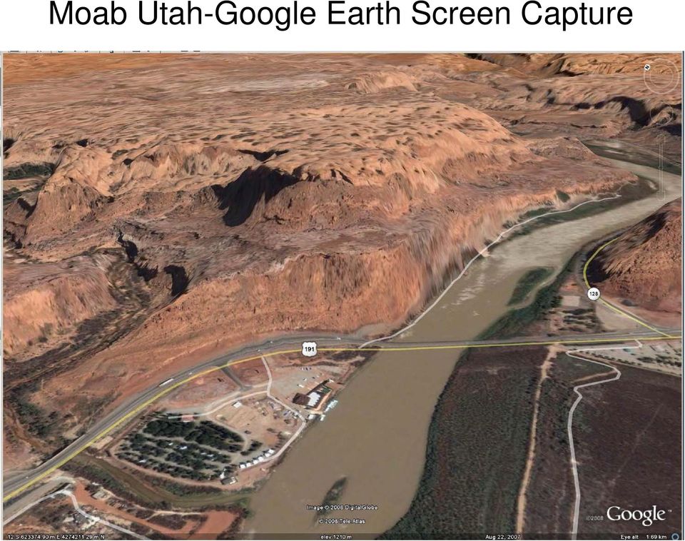
10 Moab Utah-Google Earth Screen Capture
11 Multiple Scan Positions Moab Utah

12 Scan Partition as a Function of Range

13 Scan Partition as a Function of Angle of Incidence

14 Scan Partitioning Avoids Unnecessary Scan Time

15 Scan Partitioning Scan of the Pyramid at Slaughter Canyon, Carlsbad Caverns National Monument, New Mexico Scanner was on a 200m high hill. Scan ranges were 50m to 800m

16 Scan Partitioning Scanning of the total outcrop at the scan step angle needed for the longest scan would have dramatically increased the scan time. Scanning the outcrop in a single scan which covered the entire outcrop would Result in a large amount of empty data.

17 This program help to calculate the input accuracy in degree of LPM scanner based on distance and the resolution the user wants to get Resolution Calculation

18 Types of controls

19 Placement and Survey of the Controls Use of scanned control reflectors improves the accuracy of the model and greatly reduces the effort to align the scans in Polyworks In order to align two scans, an absolute minimum of three control points are needed. It is best to have at least five. This allows for errors. If multiple scan sites are used, it is not necessary to have all of the control reflectors visible to all of the scan sites. However, it is necessary that each scan site be able to see at least three reflectors that have been correlated with the other scan sites The control reflectors should cover a wide area, do not place all of them in a linear fashion or group them in a tight bunch. The spacing of the reflectors optimally approximates or exceeds the distances in the scan region. However, this may not be practical. It is not necessary to have reflectors on the outcrop, although it is desirable to do so if practical and is aesthetically acceptable.

20 Placement and Survey of the Controls

21 Scan Reflectors before Scanning Outcrop It is best to scan the reflectors before scanning the outcrop. If you do not have the controls with the scan data, you may not be able to use the scans If something happens to disorient the scanner or there is a power or software crash during the subsequent scans, the work up to that point can still be used For double protection, rescan at least some of the reflectors after completing the outcrop scan. If the scanner has lost alignment, the final reflector scan will identify the problem. When using the LPM with the telescopic sight, the scan window must be larger than expected. There is parallax between the scanner and the telescope. This is a much larger problem at close range than at long range.
22 Photography (coaxially mounted cameras) Riegl LMS-Z620 Riegl LMP-321 Optech Ilris Mount and Rotation transformation matrices are provided with each camera image. We are still in the development of using these parameters to drape photos on the TIN models.
23 Photography (coaxially mounted cameras) The Riegl LPM scanners Physically rotate (vertically/horizontally) the laser source and detector. Maximum flexibility in the camera lens focal length Scanner will first scan the outcrop, then position the camera as required to take the photographs. The number of images and positioning of the camera is automatically done by the scanner software. Scanners with rotating mirrors (Riegl LMS series, Optech Ilris, etc) Camera focal length is selected to capture the entire scan scene Riegl LMS series (+/- 40 deg vertical) mirror rotation => 14 mm lens on a Nikon D300 camera (UTD 620 has a 20 mm lens) Optech Ilris (+/- 20 deg vertical/horizontal) mirror rotation => 20 mm lens on a Nikon D300 camera (this is hypothetical, we do not know the sensor size) Short focal length of lens limits the spatial resolution of the image Nikon D300 camera with 20 mm lens at 500 m will have a spatial resolution of 14 cm per pixel. At 1000 m it will be approximately 0.3 m per pixel Use of a longer focal length lens reduces the scan field that can be photographed with auto-alignment of the photo to the scan
24 Photography (coaxially mounted cameras) The Riegl LPM series scanners do not use rotating mirrors to traverse the scan beam. The housing is rotated vertically and horizontally. The side mounted camera can have long focal length lenses attached. The UTD LPM-800 has an 85 mm lens at 500m spatial resolution of 3 cm with a Nikon D300, 6 cm at 1000m at 500m spatial resolution of 3.8 cm with a Canon 350d, 7.6cm at 1000m (UTD s LPM uses the Canon camera) The LPM series has a beam divergence of 0.8 mradian. The LMS 620 has a beam divergence of 0.07 mradian. The LPM can have great spatial resolution for the photographs but has poor spatial resolution for the scan. The LMS has great spatial resolution for the scan but poor spatial resolution for the photograph.
25 Off Axis Cameras Cameras that are not aligned to the coordinate axes of the scanners must be registered to the scan using control tiepoints between the model and the photograph. Off axis cameras provide maximum flexibility in camera used and the focal length of the lens. We have used zoom lenses with a magnification of 12X (spatial resolution of 1 cm at 500m) Off axis cameras provide maximum flexibility in camera angle to the outcrop. Proper selection of camera location can minimize smearing of the image on the outcrop model. The quality of the draped model with off axis camera shots is controlled by the quality of the control methods that are used to tie the photograph to the model.
26 Pixel Smearing Single Photo Oblique Angle Smearing Two Photo with Optimum Angles to Outcrop Outcrop Overhang, Single Photo Smearing on Underside of Overhang
27 Pixel Smearing Pixel Elongation 10 Elongation Factor Angle to Surface The smaller the angle that is made between the optical axis of the lens and the outcrop face the greater the distortion that is contained in the image. This results in noticeable smearing of the image if the angle is smaller than about 45 o (1.4X elongation factor). The optimum angle for the photograph is 90 o.
28 Use of the IS to Register Photographs to the Model
29 Use of Topcon IS for Tiepoint Assignment Topcon IS - remotely controlled, reflectorless, imaging total station Demonstrated range of >800 meters on sandstone outcrops Use Dell ATG laptop for control (wireless LAN)
30 Log File for Photo to Model Transformation ARI01Ga04c_log.txt Input data for parameter generation - first line ARI01Ga04c.JPG 50.00mm mm mm Control point data Total number of solutions = 92 Number of unique solutions = 5 Residuals are in pixels Parameter line generated "ARI01Ga04c.JPG " Mean Squared Ordered solution set Residuals (meters) e e e e e-004 GHVM
31 Guidelines for Using the Topcon IS The total station (Topcon IS) should be close the point where the photograph was taken. The image in the photograph is very similar to the image in the IS camera and locating tiepoints between the photograph and the IS camera image is simplified. Put the IS into Wide Field mode to navigate to the region where the tiepoint has been identified in the photograph. Overlapping photographs can share common tiepoints. Pick them on only one of the photographs. Plan on 3 to 5 minutes per tiepoint Pick 6 or more tiepoints per photo, 4 is the minimum but some may not be as good as others. Errors happen. Be sure to have a laptop with a high contrast screen in full sunlight. The Dell ATG or Dell XFR are the best that we have seen to date. Use a roller-ball mouse. A conventional mouse works poorly. You will go crazy trying to use the navigation pad on the laptop. Get comfortable: camp stool and field desk.
32 Use of RTK GPS GPS is essential to georeference the model RTK quickly provides centimeter level accuracy for the model Georeferencing options: 2D or 3D (2D assumes that scanner was level) Two points (2D): scanner & one control or two controls, calculation provides no measure of error Multiple points(2d): more than two control points, calculation is a least squares solution and provides residuals for error assessment Multiple points(3d): three or more points, calculation is a least squares solution and provides residuals for error assessment Procedure Establish base station (run for at least 2 hours for OPUS-S and 15 min to 4 hours for OPUS-RS) Scan control reflectors Take GPS readings with the rover for the control reflectors and scanner (use a count of 10 for the averaging) Create the model, use the control reflector coordinates from the model, use the GeoDimensional Tools program to make the desired correction to the model coordinates.
33 Scan, Control, Photo Numbering System A very, very large number of files will be generated during a complex project. Even a simple project can have over 100 files. Keeping this straight is a major task. Variables affecting the number of files Days of the project Number of scan sites Number of photograph camera positions Number of controls One Riegl Scan creates 14 folders with multiple files in each Riscan control export files and export text files Each Photo creates 3 distorted photo files, 2 undistorted photo files, 6 ArcMap files, 5 draping files Polyworks files, GPS control files, Confusion and loss of data integrity are high probability The workflow provides a naming and number convention and software support to minimize this very complex data problem.
34 Numbering System
35 Place where you highlight the row Show all tables Add or delete record tab Description of numbering order List of Tables To generate number: Select the table from the list Highlight the row that you want from all the available tables Click generate Click copy then past the name in the folder or file name.
36 To add new record: Select the name of the target table Input the record in description and short key boxes Click insert then the new data will be inserted in the new row in the table To delete record: Select the table name Highlight the row that you need to delete Click delete Table selection
37 Action Sequence in the Field First, decide on the scan locations and ensure that they completely cover the target area. Second, decide on the location for the controls Third, review the naming and number conventions to be used Make sure that the site name in the software and the folder and site abbreviation in the camera set is correctly set (can be done night before) Set up controls and locate them with GPS Set up first scan site and decide on camera sites Scan controls before scanning the outcrop The photo team with the Topcon IS needs to be working in parallel with the scan team. One can get ahead of the other, but the jobs need to proceed in parallel. It takes a lot of time. Review the progress with each other Double check the work Save all work Review the data in the field if possible Start model construction as soon as possible in order to correct errors or fill in unintentional holes in the data
38 Demonstrations Demonstration of number system program Demonstration of the Riegl LPM or the 620 Demonstration of the Topcon IS
39 Field Work Capture an outcrop in the field for use in subsequent classes.
Processing the point cloud with RiscanPro or Riprofile. CyberMapping Lab UT-Dallas
 Processing the point cloud with RiscanPro or Riprofile CyberMapping Lab UT-Dallas RiScanPro Overview of how to import and display scans Table of Contents Window Start New Project Right Click SCANS New
The process components and related data characteristics addressed in this document are:
 TM Tech Notes Certainty 3D November 1, 2012 To: General Release From: Ted Knaak Certainty 3D, LLC Re: Structural Wall Monitoring (#1017) rev: A Introduction TopoDOT offers several tools designed specifically
Synthetic Sensing: Proximity / Distance Sensors
 Synthetic Sensing: Proximity / Distance Sensors MediaRobotics Lab, February 2010 Proximity detection is dependent on the object of interest. One size does not fit all For non-contact distance measurement,
RIEGL SYSTEM CONFIGURATION 3D TERRESTRIAL SCANNER LMS-Z390
 Holder for GPS antenna, detachable, for Nikon D70s / Nikon D100 / Nikon D200 camera mount Part-No. 02RA09-00-009-00 or for Canon EOS 1Ds Mark II camera mount Part-No. 02RA09-00-011-00 or for Canon EOS
How To Fuse A Point Cloud With A Laser And Image Data From A Pointcloud
 REAL TIME 3D FUSION OF IMAGERY AND MOBILE LIDAR Paul Mrstik, Vice President Technology Kresimir Kusevic, R&D Engineer Terrapoint Inc. 140-1 Antares Dr. Ottawa, Ontario K2E 8C4 Canada paul.mrstik@terrapoint.com
The Chillon Project: Aerial / Terrestrial and Indoor Integration
 The Chillon Project: Aerial / Terrestrial and Indoor Integration How can one map a whole castle efficiently in full 3D? Is it possible to have a 3D model containing both the inside and outside? The Chillon
Glass coloured glass may pick up on scan. Top right of screen tabs: these tabs will relocate lost windows.
 Artec 3D scanner Instructions for Medium Handheld (MH) Scanner Scanning Conditions: Objects/surfaces that don t scan well: Black or shiny objects and objects with sharp edges or points, hair, glass, transparent
4. CAMERA ADJUSTMENTS
 4. CAMERA ADJUSTMENTS Only by the possibility of displacing lens and rear standard all advantages of a view camera are fully utilized. These displacements serve for control of perspective, positioning
Full Waveform Digitizing, Dual Channel Airborne LiDAR Scanning System for Ultra Wide Area Mapping
 Full Waveform Digitizing, Dual Channel Airborne LiDAR Scanning System for Ultra Wide Area Mapping RIEGL LMS-Q56 high laser pulse repetition rate up to 8 khz digitization electronics for full waveform data
DAMAGED ROAD TUNNEL LASER SCANNER SURVEY
 University of Brescia - ITALY DAMAGED ROAD TUNNEL LASER SCANNER SURVEY Prof. Giorgio Vassena giorgio.vassena@unibs.it WORKFLOW - Demand analysis - Instruments choice - On field operations planning - Laser
U.S. Bureau of Reclamation Digital Photogrammetry Research Report
 U.S. Bureau of Reclamation Digital Photogrammetry Research Report Dam Safety Office Report No. DSO-04-01 Department of the Interior Bureau of Reclamation January 2004 U.S. Bureau of Reclamation Digital
Ultra-High Resolution Digital Mosaics
 Ultra-High Resolution Digital Mosaics J. Brian Caldwell, Ph.D. Introduction Digital photography has become a widely accepted alternative to conventional film photography for many applications ranging from
A. OPENING POINT CLOUDS. (Notepad++ Text editor) (Cloud Compare Point cloud and mesh editor) (MeshLab Point cloud and mesh editor)
 (Cloud Compare Point cloud and mesh editor) (MeshLab Point cloud and mesh editor)") MeshLAB tutorial 1 A. OPENING POINT CLOUDS (Notepad++ Text editor) (Cloud Compare Point cloud and mesh editor) (MeshLab Point cloud and mesh editor) 2 OPENING POINT CLOUDS IN NOTEPAD ++ Let us understand
MeshLAB tutorial 1 A. OPENING POINT CLOUDS (Notepad++ Text editor) (Cloud Compare Point cloud and mesh editor) (MeshLab Point cloud and mesh editor) 2 OPENING POINT CLOUDS IN NOTEPAD ++ Let us understand
IP-S2 Compact+ 3D Mobile Mapping System
 IP-S2 Compact+ 3D Mobile Mapping System 3D scanning of road and roadside features Delivers high density point clouds and 360 spherical imagery High accuracy IMU options without export control Simple Map,
Drawing Accurate Ground Plans from Laser Scan Data
 Drawing Accurate Ground Plans from Laser Scan Data Kevin Cain Institute for the Study and Integration of Graphical Heritage Techniques (INSIGHT) Abstract. In addition to the kinds of standard documentation
SE05: Getting Started with Cognex DataMan Bar Code Readers - Hands On Lab Werner Solution Expo April 8 & 9
 SE05: Getting Started with Cognex DataMan Bar Code Readers - Hands On Lab Werner Solution Expo April 8 & 9 Learning Goals: At the end of this lab, the student should have basic familiarity with the DataMan
IP-S3 HD1. Compact, High-Density 3D Mobile Mapping System
 IP-S3 HD1 Compact, High-Density 3D Mobile Mapping System Integrated, turnkey solution Ultra-compact design Multiple lasers minimize scanning shades Unparalleled ease-of-use No user calibration required
So, you want to make a photo-realistic rendering of the Earth from orbit, eh? And you want it to look just like what astronauts see from the shuttle
 So, you want to make a photo-realistic rendering of the Earth from orbit, eh? And you want it to look just like what astronauts see from the shuttle or ISS (International Space Station). No problem. Just
Mobile Mapping. VZ-400 Conversion to a Mobile Platform Guide. By: Joshua I France. Riegl USA
 Mobile Mapping VZ-400 Conversion to a Mobile Platform Guide By: Joshua I France Riegl USA Table of Contents Introduction... 5 Installation Checklist... 5 Software Required... 5 Hardware Required... 5 Connections...
SketchUp Instructions
 SketchUp Instructions Every architect needs to know how to use SketchUp! SketchUp is free from Google just Google it and download to your computer. You can do just about anything with it, but it is especially
INTEGRATED GEOPHYSICAL AND REMOTE SENSING STUDIES ON GROTTA GIGANTE SHOW CAVE (TRIESTE ITALY) P. Paganini, A. Pavan, F. Coren, A.
 P. Paganini, A. Pavan, F. Coren, A.") INTEGRATED GEOPHYSICAL AND REMOTE SENSING STUDIES ON GROTTA GIGANTE SHOW CAVE (TRIESTE ITALY) P. Paganini, A. Pavan, F. Coren, A. Fabbricatore Aerial lidar survey - strumentation Piper Seneca II - PA34
INTEGRATED GEOPHYSICAL AND REMOTE SENSING STUDIES ON GROTTA GIGANTE SHOW CAVE (TRIESTE ITALY) P. Paganini, A. Pavan, F. Coren, A. Fabbricatore Aerial lidar survey - strumentation Piper Seneca II - PA34
Applications of Advanced Laser Scanning Technology in Geology
 Applications of Advanced Laser Scanning Technology in Geology A. Fowler, Riegl USA, Orlando, United States of America J. I. France, Riegl USA, Orlando, United States of America M. Truong, Riegl USA, Orlando,
Opportunities for the generation of high resolution digital elevation models based on small format aerial photography
 Opportunities for the generation of high resolution digital elevation models based on small format aerial photography Boudewijn van Leeuwen 1, József Szatmári 1, Zalán Tobak 1, Csaba Németh 1, Gábor Hauberger
What do I do first in ArcView 8.x? When the program starts Select from the Dialog box: A new empty map
 www.library.carleton.ca/find/gis Introduction Introduction to Georeferenced Images using ArcGIS Georeferenced images such as aerial photographs or satellite images can be used in many ways in both GIS
EXPERIMENT 6 OPTICS: FOCAL LENGTH OF A LENS
 EXPERIMENT 6 OPTICS: FOCAL LENGTH OF A LENS The following website should be accessed before coming to class. Text reference: pp189-196 Optics Bench a) For convenience of discussion we assume that the light
Contents OVERVIEW WORKFLOW PROBLEM. SOLUTION. FEATURE. BENEFIT 4 5 EASY STEPS TO CALIBRATE YOUR LENSES 5
 User Guide Contents OVERVIEW PROBLEM. SOLUTION. FEATURE. BENEFIT 4 EASY STEPS TO CALIBRATE YOUR LENSES WORKFLOW 1. SETUP SPYDERLENSCAL 6 2. SETUP CAMERA 6 3. DISTANCE SETTING 7 4. SHOOTING ENVIRONMENT
3D Laser Scanning Technology. Rugged hardware and powerful software combined with streamlined survey workflow
 3D Laser Scanning Technology Rugged hardware and powerful software combined with streamlined survey workflow Maptek specialises in the research, development and application of 3D laser scanning technology.
TABLE OF CONTENTS. INTRODUCTION... 5 Advance Concrete... 5 Where to find information?... 6 INSTALLATION... 7 STARTING ADVANCE CONCRETE...
 Starting Guide TABLE OF CONTENTS INTRODUCTION... 5 Advance Concrete... 5 Where to find information?... 6 INSTALLATION... 7 STARTING ADVANCE CONCRETE... 7 ADVANCE CONCRETE USER INTERFACE... 7 Other important
Robot Perception Continued
 Robot Perception Continued 1 Visual Perception Visual Odometry Reconstruction Recognition CS 685 11 Range Sensing strategies Active range sensors Ultrasound Laser range sensor Slides adopted from Siegwart
How To Make An Orthophoto
 ISSUE 2 SEPTEMBER 2014 TSA Endorsed by: CLIENT GUIDE TO DIGITAL ORTHO- PHOTOGRAPHY The Survey Association s Client Guides are primarily aimed at other professionals such as engineers, architects, planners
ARTICLE. Which has better zoom: 18x or 36x?
 ARTICLE Which has better zoom: 18x or 36x? Which has better zoom: 18x or 36x? In the world of security cameras, 18x zoom can be equal to 36x. More specifically, a high-resolution security camera with 18x
IP-S2 HD. High Definition 3D Mobile Mapping System
 IP-S2 HD High Definition 3D Mobile Mapping System Integrated, turnkey solution High Density, Long Range LiDAR sensor for ultimate in visual detail High Accuracy IMU and DMI Odometry for positional accuracy
Leica 3D Disto Recreating the real world
 Leica 3D Disto Recreating the real world Beautifully productive Your new partner for efficient room measurement Measures in 3-dimensions with high precision. RAUM: 90/0/0 Projects point for point. Records
Paul Bryan UK Representative for CIPA English Heritage Metric Survey Team Tanner Row York, UK E-mail: paul.bryan@english-heritage.org.
 LASER SCANNING AND PHOTOGRAMMETRY: 21 ST CENTURY METROLOGY KEY WORDS: laser scanning, photogrammetry, integration David Barber, Dr Jon Mills Department of Geomatics University of Newcastle upon Tyne Newcastle
Study of the Human Eye Working Principle: An impressive high angular resolution system with simple array detectors
 Study of the Human Eye Working Principle: An impressive high angular resolution system with simple array detectors Diego Betancourt and Carlos del Río Antenna Group, Public University of Navarra, Campus
RL HW / RL HW+ / RL HGW / RL HV / RL HVPW/RL HVPW-G
 Auto-Levelling Rotary Laser Level RL HW / RL HW+ / RL HGW / RL HV / RL HVPW/RL HVPW-G 77-496 / 77-429 / 77-439 / 77-497 / 77-427/ 77-441 Please read these instructions before operating the product Auto-Levelling
I-SiTE - Laser Scanning Revolutionises Site Survey
 I-SiTE - Laser Scanning Revolutionises Site Survey I.K. Kapageridis Maptek/KRJA Systems Ltd, United Kingdom ABSTRACT: MAPTEK's revolutionary I-SiTE 3D Laser Imaging System, presented in this paper, is
A framework for disaster early recovery support using CIM model based on Photogrammetric Techniques
 A framework for disaster early recovery support using CIM model based on Photogrammetric Techniques Katsunori Miyamoto 1 1 Systems Engineering Department, Japan Construction Information Center Foundation,
2) A convex lens is known as a diverging lens and a concave lens is known as a converging lens. Answer: FALSE Diff: 1 Var: 1 Page Ref: Sec.
 A convex lens is known as a diverging lens and a concave lens is known as a converging lens. Answer: FALSE Diff: 1 Var: 1 Page Ref: Sec.") Physics for Scientists and Engineers, 4e (Giancoli) Chapter 33 Lenses and Optical Instruments 33.1 Conceptual Questions 1) State how to draw the three rays for finding the image position due to a thin
Physics for Scientists and Engineers, 4e (Giancoli) Chapter 33 Lenses and Optical Instruments 33.1 Conceptual Questions 1) State how to draw the three rays for finding the image position due to a thin
Correcting the Lateral Response Artifact in Radiochromic Film Images from Flatbed Scanners
 Correcting the Lateral Response Artifact in Radiochromic Film Images from Flatbed Scanners Background The lateral response artifact (LRA) in radiochromic film images from flatbed scanners was first pointed
Files Used in this Tutorial
 Generate Point Clouds Tutorial This tutorial shows how to generate point clouds from IKONOS satellite stereo imagery. You will view the point clouds in the ENVI LiDAR Viewer. The estimated time to complete
Rodenstock Photo Optics
 Rogonar Rogonar-S Rodagon Apo-Rodagon N Rodagon-WA Apo-Rodagon-D Accessories: Modular-Focus Lenses for Enlarging, CCD Photos and Video To reproduce analog photographs as pictures on paper requires two
New Features in TerraPhoto. Arttu Soininen Software developer Terrasolid Ltd
 New Features in TerraPhoto Arttu Soininen Software developer Terrasolid Ltd Export City Model Improvements Roof slope setting determines what polygons will be treated as walls and what as roofs Write roofs
REGISTRATION OF LASER SCANNING POINT CLOUDS AND AERIAL IMAGES USING EITHER ARTIFICIAL OR NATURAL TIE FEATURES
 REGISTRATION OF LASER SCANNING POINT CLOUDS AND AERIAL IMAGES USING EITHER ARTIFICIAL OR NATURAL TIE FEATURES P. Rönnholm a, *, H. Haggrén a a Aalto University School of Engineering, Department of Real
International Year of Light 2015 Tech-Talks BREGENZ: Mehmet Arik Well-Being in Office Applications Light Measurement & Quality Parameters
 www.led-professional.com ISSN 1993-890X Trends & Technologies for Future Lighting Solutions ReviewJan/Feb 2015 Issue LpR 47 International Year of Light 2015 Tech-Talks BREGENZ: Mehmet Arik Well-Being in
Light and its effects
 Light and its effects Light and the speed of light Shadows Shadow films Pinhole camera (1) Pinhole camera (2) Reflection of light Image in a plane mirror An image in a plane mirror is: (i) the same size
The Photosynth Photography Guide
 The Photosynth Photography Guide Creating the best synth starts with the right photos. This guide will help you understand how to take photos that Photosynth can use to best advantage. Reading it could
A System for Capturing High Resolution Images
 A System for Capturing High Resolution Images G.Voyatzis, G.Angelopoulos, A.Bors and I.Pitas Department of Informatics University of Thessaloniki BOX 451, 54006 Thessaloniki GREECE e-mail: pitas@zeus.csd.auth.gr
Geometric Optics Converging Lenses and Mirrors Physics Lab IV
 Objective Geometric Optics Converging Lenses and Mirrors Physics Lab IV In this set of lab exercises, the basic properties geometric optics concerning converging lenses and mirrors will be explored. The
Photogrammetric Point Clouds
 Photogrammetric Point Clouds Origins of digital point clouds: Basics have been around since the 1980s. Images had to be referenced to one another. The user had to specify either where the camera was in
HIGH AND LOW RESOLUTION TEXTURED MODELS OF COMPLEX ARCHITECTURAL SURFACES
 HIGH AND LOW RESOLUTION TEXTURED MODELS OF COMPLEX ARCHITECTURAL SURFACES E. K. Stathopoulou a, A. Valanis a, J. L. Lerma b, A. Georgopoulos a a Laboratory of Photogrammetry, National Technical University
Digital Photogrammetric System. Version 6.0.2 USER MANUAL. Block adjustment
 Digital Photogrammetric System Version 6.0.2 USER MANUAL Table of Contents 1. Purpose of the document... 4 2. General information... 4 3. The toolbar... 5 4. Adjustment batch mode... 6 5. Objects displaying
Consolidated Visualization of Enormous 3D Scan Point Clouds with Scanopy
 Consolidated Visualization of Enormous 3D Scan Point Clouds with Scanopy Claus SCHEIBLAUER 1 / Michael PREGESBAUER 2 1 Institute of Computer Graphics and Algorithms, Vienna University of Technology, Austria
Pro/ENGINEER Wildfire 4.0 Basic Design
 Introduction Datum features are non-solid features used during the construction of other features. The most common datum features include planes, axes, coordinate systems, and curves. Datum features do
- the. or may. scales on. Butterfly wing. magnified about 75 times.
 Lecture Notes (Applications of Diffraction) Intro: - the iridescent colors seen in many beetles is due to diffraction of light rays hitting the small groovess of its exoskeleton - these ridges are only
Experiment 3 Lenses and Images
 Experiment 3 Lenses and Images Who shall teach thee, unless it be thine own eyes? Euripides (480?-406? BC) OBJECTIVES To examine the nature and location of images formed by es. THEORY Lenses are frequently
E190Q Lecture 5 Autonomous Robot Navigation
 E190Q Lecture 5 Autonomous Robot Navigation Instructor: Chris Clark Semester: Spring 2014 1 Figures courtesy of Siegwart & Nourbakhsh Control Structures Planning Based Control Prior Knowledge Operator
Rev9 TOPCON Global Marketing Group
 Quick Start Guide Rev9 TOPCON Global Marketing Group 1/18 The flow of Data Processing 1-1 Create a new project Obtain data by remote-controlling the GLS-1000 Obtain data by standalone 2-A-1 Connect PC
Anamorphic Projection Photographic Techniques for setting up 3D Chalk Paintings
 Anamorphic Projection Photographic Techniques for setting up 3D Chalk Paintings By Wayne and Cheryl Renshaw. Although it is centuries old, the art of street painting has been going through a resurgence.
Title: The leading fusion of Laser scanning and Close range Photogrammetry Subtitle: Laser-Photogrammetric mapping of Bam Citadel (Arg-E-Bam)
") Title: The leading fusion of Laser scanning and Close range Photogrammetry Subtitle: Laser-Photogrammetric mapping of Bam Citadel (Arg-E-Bam) Abstract In the last days of the year 2003 a terrible earth
Title: The leading fusion of Laser scanning and Close range Photogrammetry Subtitle: Laser-Photogrammetric mapping of Bam Citadel (Arg-E-Bam) Abstract In the last days of the year 2003 a terrible earth
LIDAR and Digital Elevation Data
 LIDAR and Digital Elevation Data Light Detection and Ranging (LIDAR) is being used by the North Carolina Floodplain Mapping Program to generate digital elevation data. These highly accurate topographic
New Features in TerraScan. Arttu Soininen Software developer Terrasolid Ltd
 New Features in TerraScan Arttu Soininen Software developer Terrasolid Ltd Version 013.xxx Computer ID changes in licenses Send new computer ID to Terrasolid if using: Server pool licenses (server ID and
TS-E24mm f/3.5l TS-E45mm f/2.8 TS-E90mm f/2.8 Instructions
 TS-E24mm f/3.5l TS-E45mm f/2.8 TS-E90mm f/2.8 ENG Instructions Thank you for purchasing a Canon product. Canon s TS-E lenses are tilt-shift lenses designed for EOS cameras. The tilt-shift mechanism enables
OPERATING INSTRUCTIONS Nikon TiE Deconvolution Microscope CCRB 1-220G
 OPERATING INSTRUCTIONS Nikon TiE Deconvolution Microscope CCRB 1-220G Conventions Through these notes bold font refers to a software button and italics refer to a hardware switch. The software makes extensive
Scanners and How to Use Them
 Written by Jonathan Sachs Copyright 1996-1999 Digital Light & Color Introduction A scanner is a device that converts images to a digital file you can use with your computer. There are many different types
WAVELENGTH OF LIGHT - DIFFRACTION GRATING
 PURPOSE In this experiment we will use the diffraction grating and the spectrometer to measure wavelengths in the mercury spectrum. THEORY A diffraction grating is essentially a series of parallel equidistant
Introduction. Overview Topcon Technologies
 FORENSIC CATALOGUE Introduction Topcon Technologies Always innovative Overview Topcon Technologies Forensic Data Capture The scene of a crime or major disaster is an extremely taxing environment with many
3D MODELING OF LARGE AND COMPLEX SITE USING MULTI-SENSOR INTEGRATION AND MULTI-RESOLUTION DATA
 3D MODELING OF LARGE AND COMPLEX SITE USING MULTI-SENSOR INTEGRATION AND MULTI-RESOLUTION DATA G. Guidi 1, F. Remondino 2, 3, M. Russo 1, F. Menna 4, A. Rizzi 3 1 Dept.INDACO, Politecnico of Milano, Italy
18-270mm F/3.5-6.3 Di II VC PZD for Canon, Nikon (Model B008) 18-270mm F/3.5-6.3 Di II PZD for Sony (Model B008)
 18-270mm F/3.5-6.3 Di II PZD for Sony (Model B008)") R 18-270mm F/3.5-6.3 Di II VC PZD for Canon, Nikon (Model B008) 18-270mm F/3.5-6.3 Di II PZD for Sony (Model B008) Thank you for purchasing the Tamron lens as the latest addition to your photographic equipment.
R 18-270mm F/3.5-6.3 Di II VC PZD for Canon, Nikon (Model B008) 18-270mm F/3.5-6.3 Di II PZD for Sony (Model B008) Thank you for purchasing the Tamron lens as the latest addition to your photographic equipment.
Optical Digitizing by ATOS for Press Parts and Tools
 Optical Digitizing by ATOS for Press Parts and Tools Konstantin Galanulis, Carsten Reich, Jan Thesing, Detlef Winter GOM Gesellschaft für Optische Messtechnik mbh, Mittelweg 7, 38106 Braunschweig, Germany
Using Optech LMS to Calibrate Survey Data Without Ground Control Points
 Challenge An Optech client conducted an airborne lidar survey over a sparsely developed river valley. The data processors were finding that the data acquired in this survey was particularly difficult to
VENETOREGION ROAD NETWORK ROAD MAPPING LASER SCANNING FACILITY MANAGEMENT
 VENETOREGION ROAD NETWORK ROAD MAPPING LASER SCANNING FACILITY MANAGEMENT ing. Augusto Burchi burchi@sitecoinf.it Siteco profile Italian software house specialized in GIS and RDBMS dedicated to Road networks
Greg Colley, Suave Aerial Photographers
 Greg Colley, Suave Aerial Photographers Use of UAVs and low cost software for surveys of heritage sites 1. Introduction 2. Case Study: Chester Amphitheatre 3. Case Study: Chester Walls 4. Project and Equipment
Step-by-Step guide for IMAGINE UAV workflow
 Step-by-Step guide for IMAGINE UAV workflow Overview This short guide will go through all steps of the UAV workflow that are needed to produce the final results. Those consist out of two raster datasets,
DICOM Correction Item
 Correction Number DICOM Correction Item CP-626 Log Summary: Type of Modification Clarification Rationale for Correction Name of Standard PS 3.3 2004 + Sup 83 The description of pixel spacing related attributes
Optical laser beam scanner lens relay system
 1. Introduction Optical laser beam scanner lens relay system Laser beam scanning is used most often by far in confocal microscopes. There are many ways by which a laser beam can be scanned across the back
Introduction to Autodesk Inventor for F1 in Schools
 Introduction to Autodesk Inventor for F1 in Schools F1 in Schools Race Car In this course you will be introduced to Autodesk Inventor, which is the centerpiece of Autodesk s digital prototyping strategy
XXI International CIPA Symposium, 01-06 October, Athens, Greece
 2 DIFFERENT TECHNIQUES OF SCANNING CULTURAL HERITAGE 1. CLOSE-RANGE-SCANNING OF 250 CLAYFIGURINES IN XIAN, CHINA 2. LASER-SCANNING OF 3.200 DINOSAUR-STEPS IN SUCRE, BOLIVIA Stefan Linsinger a Dipl.-Ing.
9/16 Optics 1 /11 GEOMETRIC OPTICS
 9/6 Optics / GEOMETRIC OPTICS PURPOSE: To review the basics of geometric optics and to observe the function of some simple and compound optical devices. APPARATUS: Optical bench, lenses, mirror, target
Point clouds colorized by elevation of downtown Detroit, MI.
 Point clouds colorized by elevation of downtown Detroit, MI. Mobile Mapping: Fact, Fiction, or Fad? If the question What is mobile mapping and when did it start? was asked to ten different people in the
Twelve. Figure 12.1: 3D Curved MPR Viewer Window
 Twelve The 3D Curved MPR Viewer This Chapter describes how to visualize and reformat a 3D dataset in a Curved MPR plane: Curved Planar Reformation (CPR). The 3D Curved MPR Viewer is a window opened from
What is a DSLR and what is a compact camera? And newer versions of DSLR are now mirrorless
 1 2 What is a DSLR and what is a compact camera? And newer versions of DSLR are now mirrorless 3 The Parts Your camera is made up of many parts, but there are a few in particular that we want to look at
Atomic Force Microscope and Magnetic Force Microscope Background Information
 Atomic Force Microscope and Magnetic Force Microscope Background Information Lego Building Instructions There are several places to find the building instructions for building the Lego models of atomic
Image Registration. Using Quantum GIS
 Using Quantum GIS Tutorial ID: IGET_GIS_004 This tutorial has been developed by BVIEER as part of the IGET web portal intended to provide easy access to geospatial education. This tutorial is released
Fixplot Instruction Manual. (data plotting program)
") Fixplot Instruction Manual (data plotting program) MANUAL VERSION2 2004 1 1. Introduction The Fixplot program is a component program of Eyenal that allows the user to plot eye position data collected with
Fixplot Instruction Manual (data plotting program) MANUAL VERSION2 2004 1 1. Introduction The Fixplot program is a component program of Eyenal that allows the user to plot eye position data collected with
The New Canon PowerShot S95
 Press Release EMBARGO: 19 th August, 2010, 05:00 BST Pocket power for the serious photographer Canon launches the new PowerShot S95 United Kingdom, Republic of Ireland, 19 th August 2010 Canon today unveils
RIEGL VZ-400 NEW. Laser Scanners. Latest News March 2009
 Latest News March 2009 NEW RIEGL VZ-400 Laser Scanners The following document details some of the excellent results acquired with the new RIEGL VZ-400 scanners, including: Time-optimised fine-scans The
Jean François Aumont (1), Bastien Mancini (2). (1) Image processing manager, Delair-Tech, (2) Managing director, Delair-Tech. Project : Authors:
, Bastien Mancini (2). (1) Image processing manager, Delair-Tech, (2) Managing director, Delair-Tech. Project : Authors:") Jean François Aumont (1), Bastien Mancini (2). (1) Image processing manager, Delair-Tech, (2) Managing director, Delair-Tech. White paper DT26X DT-3BANDS XL APXL Project : Authors: Date:
Jean François Aumont (1), Bastien Mancini (2). (1) Image processing manager, Delair-Tech, (2) Managing director, Delair-Tech. White paper DT26X DT-3BANDS XL APXL Project : Authors: Date:
Photography of Cultural Heritage items
 Photography of Cultural Heritage items A lot of people only get to know art pieces through photographic reproductions. Nowadays with digital imaging far more common than traditional analogue photography,
Sense. 3D Scanner. User Guide
 Sense 3D Scanner User Guide COPYRIGHT NOTICE 2014 by 3D Systems, Inc. All rights reserved. This document is subject to change without notice. This document is copyrighted and contains proprietary information
Topographic Change Detection Using CloudCompare Version 1.0
 Topographic Change Detection Using CloudCompare Version 1.0 Emily Kleber, Arizona State University Edwin Nissen, Colorado School of Mines J Ramón Arrowsmith, Arizona State University Introduction CloudCompare
Spatial Adjustment Tools: The Tutorial
 Spatial Adjustment Tools: The Tutorial By Peter Kasianchuk, ESRI Educational Services In this exercise, you will perform some spatial adjustment and data management operations data to be used in analysis
Understanding Line Scan Camera Applications
 Understanding Line Scan Camera Applications Discover the benefits of line scan cameras, including perfect, high resolution images, and the ability to image large objects. A line scan camera has a single
The crime scene sketch is an invaluable aid in recording
 Chapter 4 Crime Scene Sketch The crime scene sketch is an invaluable aid in recording investigative data. It is a permanent record that provides supplemental information that is not easily accomplished
Basic Optics System OS-8515C
 40 50 30 60 20 70 10 80 0 90 80 10 20 70 T 30 60 40 50 50 40 60 30 C 70 20 80 10 90 90 0 80 10 70 20 60 50 40 30 Instruction Manual with Experiment Guide and Teachers Notes 012-09900B Basic Optics System
EPSON SCANNING TIPS AND TROUBLESHOOTING GUIDE Epson Perfection 3170 Scanner
 EPSON SCANNING TIPS AND TROUBLESHOOTING GUIDE Epson Perfection 3170 Scanner SELECT A SUITABLE RESOLUTION The best scanning resolution depends on the purpose of the scan. When you specify a high resolution,
Making High Dynamic Range (HDR) Panoramas with Hugin
 Panoramas with Hugin") Making High Dynamic Range (HDR) Panoramas with Hugin Dr Ryan Southall - School of Architecture & Design, University of Brighton. Introduction This document details how to use the free software programme
Making High Dynamic Range (HDR) Panoramas with Hugin Dr Ryan Southall - School of Architecture & Design, University of Brighton. Introduction This document details how to use the free software programme
Endoscope Optics. Chapter 8. 8.1 Introduction
 Chapter 8 Endoscope Optics Endoscopes are used to observe otherwise inaccessible areas within the human body either noninvasively or minimally invasively. Endoscopes have unparalleled ability to visualize
TRIMBLE TX5 3D LASER SCANNER QUICK START GUIDE
 TRIMBLE TX5 3D LASER SCANNER QUICK START GUIDE Equipment 1 8 9 5 6 7 4 3 2 The TX5 laser scanner ships with the following equipment: 1 Scanner transport and carry case 6 USB memory card reader 2 AC power
RIEGL VZ-4000. Terrestrial Laser Scanning. 3D Very Long Range Terrestrial Laser Scanner with Online Waveform Processing
 3D Very Long Range Terrestrial Laser Scanner with Online Waveform Processing RIEGL VZ-4000 very long range up to 4000 m eye safe operation at Laser Class 1 wide field of view, 60 x 360 high speed data