TECHNICAL SERVICE GUIDE
|
|
|
- Anis Cross
- 8 years ago
- Views:
Transcription
1 g GE Consumer Home Services Training TECHNICAL SERVICE GUIDE General Electric Side-by-Side Knob Control/Metal Liner Refrigerator MODEL SERIES: GSS20 GSS22 GSS25 ESS22 ESS25 HSS22 HSS25 SSS25 PUB # /01

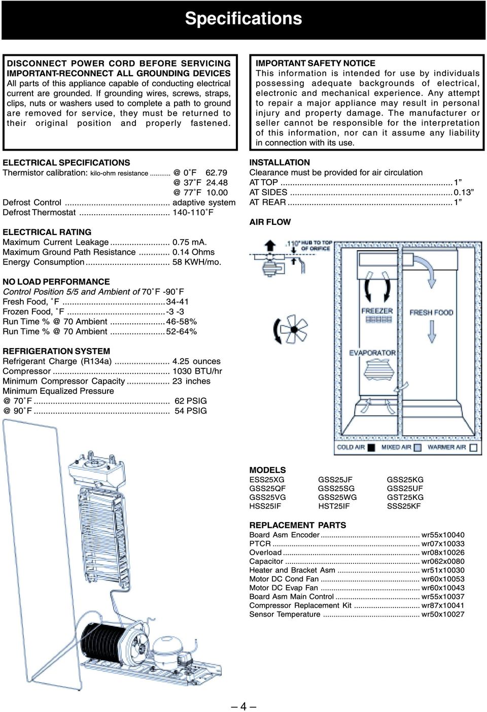
2 ! IMPORTANT SAFETY NOTICE The information in this service guide is intended for use by individuals possessing adequate backgrounds of electrical, electronic, and mechanical experience. Any attempt to repair a major appliance may result in personal injury and property damage. The manufacturer or seller cannot be responsible for the interpretation of this information, nor can it assume any liability in connection with its use. WARNING To avoid personal injury, disconnect power before servicing this product. If electrical power is required for diagnosis or test purposes, disconnect the power immediately after performing the necessary checks. RECONNECT ALL GROUNDING DEVICES If grounding wires, screws, straps, clips, nuts, or washers used to complete a path to ground are removed for service, they must be returned to their original position and properly fastened. GE Consumer Home Services Training Technical Service Guide Copyright 2001 All rights reserved. This service guide may not be reproduced in whole or in part in any form without written permission from the General Electric Company.

3 Table of Contents Introduction Installation Specifications menclature Warranty Information Operating Characteristics General Locator Views Mechanical Disassembly Diagnostics Component and Connector Locator Views Schematics Illustrated Parts Catalog

4 Introduction 2001 Energy SxS models are being introduced in response to the requirement for more energyefficient refrigerators by mid year 2001, along with having feature and operation enhancements. The primary differences in this refrigeration system are the adaptive defrost system (see Pub. # ), control board, software, and control systems that operate independently in fresh food and freezer sections. The new high-efficiency control system has the ability to cycle components and adjust fan speeds as required to maintain temperaturesetting ranges in freezer and fresh food sections. Feedback systems are digital inputs and relay outputs. Sensors (thermistors) are used to measure temperature with communications to a main PC board, which controls the unit components. The refrigerator has versions that have control knobs or touchpads (Profile models) to provide inputs to a microprocessor. The freezer/ fresh food controls are temperature setpoint type and have settings of 0-9 with 9 being the coldest temperature possible. The new NO CLEAN condenser is serviceable from the rear and is designed to prevent the customer from having to clean the condenser in normal usage conditions. The freezer has adjustable shelves, slide-out Spillproof shelf, QuickSpace shelf, and deep door shelves, based on model. The fresh food section has a baking soda holder, fruit and vegetable drawer, drawer dividers, adjustable humidity drawer, and convertible meat drawer. This new high-efficiency refrigerator is a combination of the most efficient refrigeration system and the most desirable customer features available. Sealed system operation and compressor are functionally the same as previous models, with some minor changes. The 20', 22', and 25' side-by-side models are the models affected. These models are available with through-the-door chilled water and ice dispenser, and built-in water filter feature. On models requiring icemaker, the newest electronic icemaker (see Pub. # ) has been or can be installed. 2

5 Installation FOR A QUALITY INSTALLATION, ATTENTION INSTALLER: FOLLOW THESE INSTRUCTIONS. ROLLERS CARDBOARD PROTECTS DOOR À DO NOT OVER- TIGHTEN STRAP RAISE IS COLDEST 0 IS OFF HEX-HEAD BOLTS (4) REMOVE AND DISCARD SKIDBOARDS and bolts used to hold skidboards. Use PADDED HAND TRUCK to protect refrigerator finish. MAKE SURE FRONT ROLLERS DO NOT REST ON TRUCK TRUCK FROM SIDE ONLY LEAVE TAPE ON DOORS until refrigerator is in its final location. ROLLER ADJUSTMENT ADJUST FRONT ROLLERS so that refrigerator is solid and doors close easily. MAKE SURE DOORS ARE EVEN AT TOP. Check gasket seal. 0 FREEZER FRESH FOOD SET BOTH CONTROLS TO 5. SET ICEMAKER TO OFF until water line is connected. IMPORTANT: IMMEDIATELY REMOVE ALL CLEAR PROTECTIVE TAPE FROM TRIM. TO REMOVE TAPE RESIDUE AND HANDPRINTS, USE APPLIANCE POLISH. REMOVE ALL TAPE AND OTHER PACKAGING MATERIAL FROM INSIDE REFRIGERATOR. DO NOT REMOVE SERIAL PLATE. IF NECESSARY TO REMOVE DOORS, REMOVE ALL HINGES. FOR DISPENSER MODELS: TO REINSTALL DOORS... WHEN INSTALLING DOORS... HINGE COVER COLLAR PRESS THE WHITE COLLAR AS YOU PULL OUT THE TUBING. TUBING CLIP At lower left hinge, remove tubing from the clip. Disconnect the water line Push tubing into connector ( 5 8 to 3 4 ) to prevent leakage. WIRING CONNECTORS At upper hinges, disconnect wiring connectors. Remove both hinges with each door to prevent damage to tubing or wiring. ALIGN DOORS EVENLY AT TOP FRESH FOOD HINGE ADJUSTMENT PIN Reinstall lower hinges and tighten hinge screws firmly. Place door on lower hinge pin and install upper hinges. Tighten upper hinge screws firmly. Align both doors evenly at top by adjusting pin on lower fresh food hinge. Reconnect wiring connectors and reinstall hinge covers. Reinstall tubing by pushing tubing into connector. Put tubing back into clip. FRANÇAIS ESPANOL PREFERRED METHOD MAKE SURE PROPER GROUND EXISTS BEFORE USE TEMPORARY METHOD (Adapter plugs not permitted in Canada) ENSURE PROPER GROUND AND FIRM CONNECTION BEFORE USE IMPORTANT: PLEASE READ CAREFULLY FOR PERSONAL SAFETY, THIS APPLIANCE MUST BE PROPERLY GROUNDED. The power cord of this appliance is equipped with a three-prong (grounding) plug that mates with a standard three-prong (grounding) wall receptacle to minimize the risk of electric shock hazard from this appliance. The customer should have the wall receptacle and circuit checked by a qualified electrician to make sure the receptacle is properly grounded. Where a standard two-prong wall receptacle is encountered, it is the personal responsibility and obligation of the customer to have it replaced with a properly grounded three-prong wall receptacle. DO NOT, UNDER ANY CIRCUMSTANCES, CUT OR REMOVE THE THIRD (GROUND) PRONG FROM THE POWER CORD. USAGE SITUATIONS WHERE THE APPLIANCE S POWER CORD WILL BE DISCONNECTED INFREQUENTLY Because of potential safety hazards under certain conditions, we strongly recommend against the use of an adapter plug. However, if you still elect to use an adapter, where local codes permit, a TEMPORARY CONNECTION may be made to a properly grounded two-prong wall receptacle by the use of a UL listed adapter which is available at most hardware stores. The larger slot of the adapter must be aligned to provide proper polarity in the connection of the power cord. CAUTION: Attaching the adapter ground terminal to the wall receptacle cover screw does not ground the appliance unless the cover screw is metal, and not insulated, and the wall receptacle is grounded through the house wiring. The customer should have the circuit checked by a qualified electrician to make sure the receptacle is properly grounded. When disconnecting the power cord from the adapter, always hold the adapter with one hand. If this is not done, the adapter ground terminal is very likely to break with repeated use. Should this happen, DO NOT USE the appliance until a proper ground has again been established. USAGE SITUATIONS WHERE THE APPLIANCE S POWER CORD WILL BE DISCONNECTED FREQUENTLY Do not use an adapter plug in these situations because frequent disconnecting of the power cord places undue strain on the adapter and leads to eventual failure of the adapter ground terminal. The customer should have the two-prong wall receptacle replaced with a three-prong (grounding) receptacle by a qualified electrician before using the appliance. 197D3266P JR 3

6 Specifications 4
7 menclature ENGINEERING NOMENCLATURE CONFIGURATION S = SIDE-BY-SIDE REF. VOLUME 20 / 22 / 25 CU. FT. MODEL YEAR M = 2001 A = INIITIAL DESIGN B = 1ST REVISION ETC. DOOR TYPE F = FLAT DOOR GSS25IFMAFWW BRAND/PRODUCT DEPTH/POWER INTERIOR/SHELVES ICEMAKER/EXTERIOR EXTERIOR COLOR G= GE H = HOTPOINT P = PROFILE (GE) E = ETERNA (GE) R = RCA S = SELECT (GE) S = STANDARD DEPTH T = TROPICAL G = GLOBAL A = LEADER WIRE D = DELUXE WIRE I = DELUXE GLASS K = SPILL PROOF/SLIDE-OUT GLASS M = SPILL PROOF/SLIDE-OUT GLASS & QUICK SPACE Q = SHOWCASE DERIVATIVE U = AVB DERIVATIVE W= HPS (CONTRACT) DERIVATIVE X = REGIONAL DERIVATIVE B = NON-DISPENSER / ICE-MAKER READY D = CUBED ICE / WATER E = CUBED & CRUSHED ICE / WATER F = 6 MO. FILTER / CUBED & CRUSHED ICE G = 1 YR. FILTER / CUBED & CRUSHED ICE I = IN-LINE FILTER / INDICATOR & C/C/W WW = WHITE/WHITE AA = ALMOND/ALMOND BB = BLACK/BLACK CC = BISQUE/BISQUE WH = WHITE/BLACK AD = ALMOND/BLACK GEA00687 te: Mini Manual/Tech Data Sheet is located in a plastic bag in the control console. 5
 DERIVATIVE X = REGIONAL DERIVATIVE B = NON-DISPENSER / ICE-MAKER READY D = CUBED ICE / WATER E = CUBED & CRUSHED ICE / WATER F = 6 MO.")
8 Warranty Information Sales slip or cancelled check is required as proof of original purchase date to obtain service under warranty. te: Water filter cartridge warranty is 30 days. All warranty service is provided by our Factory Service Centers or an authorized Customer Care technician. F or The Period Of: GE Will Replace: One Year From the date of the original purchase Five Years From the date of the original purchase Lifetime From the date of the original purchase Any part of the refrigerator which fails due to a defect in m aterials or workmanship. During this full one-year warranty, G E will also provide, free of charge, all labor and in-home service to replace the defective part. Any part of the sealed refrigerating system (the compressor, condenser, evaporator, and all connecting tubing) which fails due to a defect in materials or w orkmanship. During this five-year warranty, GE will also p rovide, free of charge, all labor and in-home service to r eplace the defective parti n the sealed refrigerating system. t. Any see-through pan or drawer furnished with the refrigerator if the pan or drawer breaks during normal household use. Drawer covers are not included. During this limited lifetime warranty, you will be responsible for any labor or in-home service costs. What GE Will t Cover: Service trips to your home to teach you how to use the product. Improper installation. Failure of the product if it is abused or used for other than the intended purpose or used commercially. Loss of food due to spoilage. Replacement of house fuses or resetting of circuit breakers. Replacement of the water filter cartridge due to water pressure that is outside the specified operating range or due to excessive sediment in the water supply. Replacement of water filter cartridge after its expected useful life, 30 days. Damage to the product caused by accident, fire, floods, or acts of God. Incidental or consequential damage caused by possible defects with this appliance. This warranty is extended to the original purchaser and any succeeding owner for products purchased for home use within the USA. In Alaska, the warranty excludes the cost of shipping or service calls to your home. Some states do not allow the exclusion or limitation of incidental or consequential damages. This warranty gives you specific legal rights, and you may also have other rights which vary from state to state. To know what your legal rights are, consult your local or state consumer affairs office or your state s Attorney General. Warrantor: General Electric Company. Louisville, KY

9 Operating Characteristics Table of Contents rmal Operating Characteristics That Are Different from Previous Models.. 8 Abnormal Operating Characteristics (Incorrect Operation) Adaptive Defrost Cooling Operation (Adaptive Defrost) Pre-Chill Operation (Adaptive Defrost) Defrost Heater Operation (Adaptive Defrost) Dwell Period (Adaptive Defrost) Post Dwell (Adaptive Defrost) Liner Protection Mode Dispensing Functions Dispenser Light Dispenser Lock Filters Hinge System and Door Closure Airflow (Cabinet Interior) Jelly Roll Condenser Main Control Board

10 rmal Operating Characteristics That Are Different from Previous Models Icemaker auger rotates clockwise. Evaporator fan running, without compressor or condenser fan. Post Dwell (Adaptive Defrost), compressor, and condenser fan on with evaporator fan off after defrost cycle. Liner Protection Mode, fan comes on when the doors are open for 3 minutes. Evaporator fan and compressor can run continuously for 2 hours (Adaptive Defrost). Different sound levels can be heard when the fan changes speed. Response time for drastic temperature change is 2 to 10 minutes. The main control board will only respond to 8 degrees (Fahrenheit) of temperature change per minute as determined by resistance of sensor. Abnormal Operating Characteristics (Incorrect Operation) Evaporator fan on, compressor off, and damper shut (except liner protection mode). Rapid fan speed changes, fan takes at least 1 minute to change speeds. Compressor running without the condenser fan. The compressor and condenser fan should always run at the same time. Adaptive Defrost Adaptive Defrost can be described as a defrost system that adapts to a refrigerator s surrounding environment and household usage. Unlike conventional defrost systems that use electromechanical timers with a fixed defrost cycle time, Adaptive Defrost utilizes an intelligent, electronic control to determine when the defrost cycle is necessary. In order to accomplish the correct defrost cycle time, the main control board monitors the following refrigerator operations: Length of time the refrigerator doors were open since the last defrost cycle. Length of time the compressor has run since the last defrost cycle. Amount of time the defrost heaters were on in the last defrost cycle. Adaptive Defrost is divided into 5 separate cycles. Those operations are: Cooling Operation Pre-Chill Operation Defrost Heater Operation Dwell Period Post Dwell (See Pub. # for more information on Adaptive Defrost.) Cooling Operation (Adaptive Defrost) During the cooling operation, the main control board monitors door opening (fresh food and freezer doors) and compressor run times. The board counts the time the doors are open. It reduces the length between defrosts by 255 seconds (multiplication factor) for each second that each door is open. If both doors are open, it reduces it by twice the amount. The multiplication factor reduces compressor run time. If the doors are not opened, the compressor will run up to 60 hours between defrosts. If the doors are opened frequently and/or for long periods of time, the compressor run time between defrosts will be reduced to as little as 8 hours. Pre-Chill Operation (Adaptive Defrost) F R EE Z E R A I R T E M PE R A T U R ES F / C 25 / / / / / / / / / / :00 PRE-CHILL MODE 09:00 10:00 11:00 12:00 13:00 14:00 15:00 16:00 17:00 18:00 Pre-Chill Defrost When the main control board determines that defrost is necessary, it will force the refrigerator 8

11 into a continuous cool mode (pre-chill). During prechill, the freezer temperature may be driven below the set point. However, the fresh food temperature will be regulated by the damper. Pre-chill will last for 2 hours. These models do not have a defrost holdoff. Defrost Heater Operation (Adaptive Defrost) After 2 hours of pre-chill operation, the main control board turns off the compressor, condenser fan, and evaporator fan. During defrost operation, the main control board monitors the evaporator temperature using evaporator thermistor inputs. The thermistor will terminate defrost heater operation in less than 45 minutes. Typical defrost time is minutes. Maximum defrost cycle is 45 minutes with heater on, 5 minutes in dwell. The defrost system is protected by a defrost safety thermostat (switch). The thermostat opens when the evaporator temperature raises to 140 F and closes when the evaporator temperature lowers to 110 F. Dwell Period (Adaptive Defrost) After defrost heater operation has been terminated by the main control board, a 5-minute dwell period occurs. During this period, the compressor, condenser fan, and the evaporator fan remain off. The remaining frost melting from the evaporator will continue to drip and drain so that prior to the cooling operation, the evaporator will be totally clear of any moisture. After the 5-minute dwell period, the unit goes into post dwell. Post Dwell (Adaptive Defrost) The post dwell period is designed to cool the evaporator before circulating air within the refrigerator. This prevents any residual heat on the evaporator from being distributed in the freezer. During this period, the compressor is on and the condenser fan is on, but the evaporator fan is off, and the damper is closed. Post dwell lasts 10 minutes on these models. Liner Protection Mode The liner protection mode will activate if either of the doors have been open for 3 minutes. This mode will start the evaporator fan and close the damper. This mode is controlled by 2 timers. Timer #1 monitors door-open time. A 3-minute door-open count begins when the door is opened. If 3 minutes elapse before the door is closed, the liner protection mode will become active. Once the door is closed, timer #1 resets and liner protection mode goes into standby. In standby, normal fan and damper operations resume and timer #2 begins a 3-minute door-closed count. If 3 minutes elapse without a door opening, liner protection mode will completely deactivate. If a door is opened within the timer #2 door-closed count, the remaining time in the door-closed count will be deducted from the timer #1 door-open count. Dispensing Functions The water, crushed ice, and cubed ice functions are controlled by the main control board. To select a function, press the appropriate pad on the dispenser. The LED will light to identify the selection. To dispense the selected item, depress the dispenser cradle located in the dispenser recess. The solenoid and linkage assembly will open the ice chute door to dispense the ice. If cubed ice is selected, the crushed ice bypass solenoid will allow cubed ice to bypass the ice crusher. The ice chute door must remain open for 5 second after dispensing ceases. After this 5 second delay, the solenoid and linkage assembly will shut the ice chute door. The dispenser light will come on automatically when the dispenser cradle is depressed and will fade out 5 seconds after it is released. Dispenser Light The LIGHT pad turns the dispenser light on and off. When the light is turned off, it will fade out. The dispenser light will come on automatically when the dispenser cradle is depressed and will fade out 5 seconds after it is released. The LIGHT pad will not turn off the light during dispense. 9

12 Dispenser Lock When the dispenser system is locked, no dispenser command will be accepted. This includes the dispenser cradle and will prevent accidental dispensing that may be caused by children or pets. If a pad is pressed with the system locked, it will be acknowledged with 3 pulses of the LOCK LED accompanied by an audible tone. To lock or unlock communication between the dispenser and main control board, press the LOCK pad and hold it for 3 seconds. The LOCK LED will flash while the LOCK pad is pressed. When the communication is locked, the LOCK LED will be illuminated. Hinge System and Door Closure Cam with Thimble Screw Cam Riser Hinge Adjustment Pin Hinge GEA00909 The status of other functions selected prior to the initiation of the lock feature will be displayed. If the lock is engaged while a mode is active, the LED will remain on until that mode times out. If the lock is engaged when the filter timer expires, the LED will come on but cannot be reset until the lock is turned off. The lock feature will be restored in the event of a power disruption. Filters Some models are equipped with a water filter located in the upper right-hand corner of the fresh food compartment. The filter is designed to be used for up to 8 hours of open valve time or 1 year of calendar time. The hinge brackets are not adjustable on the cabinet. The fresh food door can be adjusted up and down by using the hinge adjustment pin (located on the fresh food lower door hinge). The fresh food and freezer lower door hinges are equipped with replaceable cam risers. The cam risers assist in door closure. If the fresh food door is adjusted too high, cam riser will not be engaged, and the fresh food door will not close properly. IMPORTANT: The refrigerator rollers must be adjusted correctly for proper door closure. When the rollers are adjusted correctly, the door should close easily when open approximately 45 degrees (halfway) When 90% of filter time (dependant on model) has elapsed (open valve time or calendar time, whichever comes first), the main control board will illuminate the filter reminder LED (amber). When 100% of the filter time has elapsed, the main control board will illuminate the filter reminder LED (red). 10

13 Airflow (Cabinet Interior) Jelly Roll Condenser The freezer compartment is designed so that when the evaporator fan is operating, air is drawn into the bottom of the air tunnel and through the evaporator. The cold air is then pushed out into the top of the freezer. The fresh food compartment receives chilled air via an electronic damper positioned at the top, rear of the refrigerator between the freezer compartment and the fresh food compartment. The damper is controlled by the main control board and when open, allows chilled air from the freezer air tunnel to move into the fresh food compartment. Air returns from the fresh food compartment to the freezer compartment via a vent located to the left of the FRESH PRODUCE drawer. The new NO CLEAN condenser is accessed from the rear and is designed to be tolerant of up to 2 inches of lint. The idea is that the consumer, in normal operating conditions, will never have to clean the condenser. If necessary, only an ordinary appliance brush is used. Air is drawn in from the outside diameter of the condenser and pulled out by the condenser fan. A condenser fan baffle is located at the rear to direct airflow through the condenser. Functionally, the condenser does the same job as previous models. Air is drawn in from front left and rear left and exits out front right side of refrigerator. 11

14 Main Control Board COMMUNICATION INPUT/OUTPUT DAMPER COILS ENCODER INPUTS THERMISTOR INPUTS MODEL SELECT J4 J3 J1 1 J5 PAN_HTR 6 1 K1 AUGER COMM 2 +12V 3 -COM 4 DI 5 DO INPUTS ACCUMULATED FF AND FRZ DOOR OPENINGS (MINUTES) FAN OUTPUTS COMPRESSOR RUN TIME (MINUTES) J2 8 DEFROST HEATER ON TIME (MINUTES) J6 2 1 L1 COMP PROCESSING UNIT DEFR LINE K3 DEFROST K5 QC N DFZ DFF OCH K7 PAN/HTR COMMON WATER CRUSHER AUGER K6 WATER OUTPUTS K4 COMP K2 C/CR COOLING PRE-CHILL DEFROST J7 COMPRESSOR AND DEFROST OUTPUTS DOOR SWITCH INPUTS 12

15 General Locator Views Temperature Controls Tech Data Sheet Location Freezer Light Switch Fresh Food Light Switch Damper Evaporator Fan Fresh Food Thermistor Evaporator Thermistor Evaporator Freezer Thermistor GEA

16 Main Control Board Condenser Fan Jelly Roll Condenser Compressor Water Solenoids Capacitor Overload and Relay (under cover) GEA
")
17 Mechanical Disassembly Table of Contents Door Gasket Door Handles Doors and Door Hinges Door Removal Fresh Food Door Adjustment Control Panel Fresh Food Light Freezer Door Light Switch Water Filter Cartridge Shelves Drawers and Bins Door Shelf Extenders Freezer Light Icemaker Ice Dispenser Drive Evaporator Fan Defrost Heater and Freezer Thermistor Overtemperature Thermostat and Evaporator Thermistor

18 Fresh Food Thermistor Door Dispenser Control Panel Door Dispenser Target Switch Ice Crusher Ice Dispenser Drive Motor Ice Cube Solenoid Evaporator Condenser Fan Dispenser Heater Main Control Board Roller Assembly Water Solenoid Fresh Food Air Damper

19 Door Gasket The rear flange of the gasket is positioned between the inner and outer door panels. The screws under the gasket flap must be loosened. 1. Remove the door bins. 2. Loosen 40 screws located under the door gasket. 3. Remove the gasket from the interior of the door liner. te: The back side of the door liner has doublesided tape at the corners. Doors and Door Hinges IMPORTANT: The freezer door is not adjustable. The fresh food door can be adjusted up and down to match the height of the freezer door. Adjust the fresh food door up or down using the hinge adjustment pin (located on the fresh food lower door hinge). Door Handles Screws GEA00866 Door handles are front mounted and secured with Torx-style screws. 1. Remove the handle trim covers by inserting a thin flat-blade screwdriver about 2 in. from the end of top cover trim. Pry up enough to insert your fingers and lift to free trim from 2 plastic locking tabs inserted in rectangle door holes. Reverse to reinstall, taking care to align cover trim correctly. The top and bottom are not interchangeable. 2. Remove 2 T-20 Torx screws from the upper and lower ends of the handle. 3. Remove the handle. The fresh food and freezer lower door hinges are equipped with replaceable cam risers. Cam risers assist in door closure. When the fresh food door is adjusted too high, the cam riser will not be engaged. If the cam riser is not engaged, the door will not close properly. Refer to the Fresh Food Door Adjustment section in this chapter for more information. IMPORTANT: The refrigerator rollers must be adjusted correctly to ensure proper door closure. Refer to the Roller Assembly section in this chapter for more information. Door Removal 1. Remove the upper hinge cover by removing the Phillips screw. 2. With the door in the closed position, disconnect the wiring harness (freezer side only). 17
.")
20 Cam with Thimble Screw 3. Remove the base grille. 4. Disconnect the water supply tube. To disconnect the tube, push in the white collar on the quick connector and pull the tube out. Cam Riser Hinge Adjustment Pin Hinge GEA Remove the screw, hinge cam, and thimble from the bottom of the door. 10. Fresh Food Door Only: Remove the hinge adjustment pin and cam riser from the lower hinge. 11. Freezer Door Only: Remove the cam riser and washer from the lower hinge. 12. Remove 2 screws and lower hinge from cabinet. Fresh Food Door Adjustment GEA Remove the water tube protection (black collar). 6. Remove 2 upper hinge screws. 7. Lift the upper hinge and move it to the side (the gasket is located under the hinge). CAUTION: Do not side-load hinges. NOTE: Freezer door only - Guide the water line through hinge while lifting the door from hinge. 8. Open the door 90 degrees and lift the door straight up and off the lower hinge. IMPORTANT: The refrigerator rollers must be adjusted correctly to ensure proper door closure. Refer to the Roller Assembly section in this chapter for more information. The freezer door is not adjustable. The fresh food door can be adjusted to match the height of the freezer door. 1. Remove the base grille (opening the door makes grille removal easier). 2. Turn the hinge adjustment pin (located on the fresh food lower hinge) clockwise to raise the door and counterclockwise to lower the door. Control Panel The control panel, located at the front of the fresh food compartment, contains temperature control encoders for fresh food and freezer sections and the fresh food door light switch. 1. Remove 2 screws located in the bottom of the control panel. Slide the panel down. 18
. 6. Remove 2 upper hinge screws. 7.")
21 2. Disconnect the connectors for the door light switch and temperature control switches. Connectors Encoder Board GEA Disconnect the connectors for the light and temperature control encoders. 4. Disconnect the temperature control encoder connector. 5. Remove the mounting nuts for both encoders. te: Both switches must be replaced because they are mounted on a common circuit board. Freezer Door Light Switch The freezer door light switch is located on the left of the freezer compartment. 1. Slide a small flat-blade screwdriver under the switch and push the locking tab. Pull out the switch. 2. Disconnect the harness connector and remove the switch. Mounting Nuts GEA Disconnect the refrigerator door light switch supply connector. 7. Push the locking tab in and slide the switch out of the panel. Fresh Food Light The lower fresh food light is located under an opaque cover in the lower portion of the fresh food compartment in some models. te: The upper light cover removal is covered in the previous procedure. 1. Remove the lower light cover by lifting it off the dowels. 2. Remove 2 40-watt appliance light bulbs. Water Filter Cartridge te: The water filter should be replaced every 6 months. Warranty life is 30 days. The water filter cartridge is located in the upper right corner of the fresh food compartment. When the LED illuminates, change the water filter. On those models without the LED, change the filter when the water flow decreases to the dispenser or icemaker. 1. Remove the old cartridge by slowly turning it to the left. Do not pull the cartridge down. A small amount of water may drip when the cartridge is removed. 19
22 2. On models without a replacement LED, apply the year and month sticker to the new cartridge. 3. Line up the arrow on the cartridge with the cartridge holder. Place the new cartridge up and inside the holder. Do not push it into the holder. 4. Slowly turn the cartridge to the right until it stops (about 1/2 turn). Do not overtighten. The cartridge will automatically raise itself into position. 5. Run water from the dispenser for 3 minutes (about 1-1/2 gallons) to clear the system and prevent sputtering. 6. On models with the LED, press and hold the RESET WATER FILTER pad on the dispenser. te: A filter bypass plug must be used if a replacement filter is not available. The dispenser and icemaker will not operate without a filter or the filter bypass plug installed. The QuickSpace shelf splits in half and slides under itself to allow for storage of tall items on the shelf below. To adjust this shelf: 1. Tilt the shelf up until the tab disengages from the shelf track. 2. Lift the lower tab out of the shelf track. 3. Slide the front half of the shelf under the back half. GEA00873 Drawers and Bins Water Filter Cartridge Shelves GEA00729 The slide-out and Spillproof shelves allow access to items stored behind other items. Spillproof shelves have special edges to help prevent spills from dripping onto lower shelves. The refrigerator uses drawers (fresh food) and bins (freezer) to store food. Adjustable humidity drawers allow vegetables to be stored at high humidity or fruits at low humidity. A convertible meat drawer with variable control regulates cold air from the freezer compartment to circulate around the drawer. 1. Pull out the drawer or bin until it reaches the mechanical stops. 2. Lift the drawer or bin up and pull it out of the compartment. 20
23 Freezer Light The freezer light is attached to the evaporator fan housing. 1. Remove the light cover by lifting it off the tabs. 2. Replace the appliance light bulb. GEA00874 Icemaker The icemaker is located in the rear of the freezer compartment. The icemaker must be replaced as a complete unit. Door Shelf Extenders GEA00875 Detachable shelf extenders deepen and enclose fixed door shelves, providing more storage and greater storage flexibility. 1. Lift the shelf extender straight up until it disengages from the locking device. 2. Pull out the shelf extender. 1. Slide out the upper icemaker dispenser tray and drawer. 2. Loosen 2 mounting screws. GEA
24 Mounting Screws Splash Baffle GEA00879 Ice Dispenser Drive The ice dispenser drive turns the ice dispenser auger in either crushed or cube mode. 1. Remove 2 Phillips screws from the ice dispenser drive. 2. Slide the dispenser out until the cable connector is visible. 3. Disconnect the cable and remove the dispenser drive. 3. Lift up the icemaker and slide it out until the cable connection is exposed. te: When replacing the icemaker, the fill cup and splash baffle must be reused. 4. Disconnect the cable connector. 2 Screws GEA00882 Cable Connector GEA00880 Evaporator Fan The evaporator fan, located in the upper portion of the freezer compartment, circulates cold air through the fresh food and freezer compartments. 1. Remove auger motor housing. 2. Loosen 4 Phillips screws located in the lower portion of the evaporator fan duct. 3. Lift up the duct and slide it out. 5. Loosen 3 screws on the icemaker bracket. 6. Lift up the bracket and slide it out. 3 Screws GEA
25 4. Remove 4 Phillips screws from the evaporator cover. 5. Remove the evaporator cover. 6. Disconnect the evaporator fan cable connectors and the ground wire. 7. Loosen 2 Phillips screws from the evaporator fan mounting. 2 Connectors Defrost Heater and Freezer Thermistor The defrost heater warms the evaporator during the defrost mode of operation. The freezer thermistor, located at the bottom left side of the freezer compartment, senses the temperature in the freezer. 1. Complete steps 4 and 5 in the previous procedure. 2. Remove 2 Phillips screws from the defrost heater. 3. Remove the heater. 2 Screws GEA Screws 8. Pull out the fan and remove the light and defrost heater wiring harness. 9. Remove the fan. GEA Remove the freezer thermistor. Heater Wiring Harness Freezer Thermistor GEA00885 GEA
26 Overtemperature Thermostat and Evaporator Thermistor The main control board monitors the resistance of the evaporator thermistor. The main control board will terminate the defrost cycle when a predetermined temperature (60 F) is reached. The over-temperature thermostat is a redundant defrost terminating device. It will also terminate defrost in the event of a failure of the evaporator thermistor. 1. Remove the overtemperature thermostat. 2. Remove the evaporator temperature thermistor. Door Dispenser Control Panel The door dispenser control panel allows the consumer to select water, crushed ice, or ice cubes. It is an interface to the main control board. Evaporator Temperature Thermistor Over-Temperature Thermistor 1. Use a screwdriver to unlock the tabs at the bottom of the control panel. Slide the bottom out and down. Fresh Food Thermistor GEA00888 The fresh food thermistor, located in the top, left of the fresh food compartment, hidden behind the bin track at the top left, senses the compartment temperature. 1. Disengage the plastic track by sliding upward and remove the housing. 2. Remove the thermistor from the housing. 2. Disconnect the wiring harness connectors. te: Inner door panel must be removed to remove recess trim. Door Dispenser Target Switch When depressed, the door dispenser target switch allows water, ice cubes, or crushed ice to be dispensed. 1. Remove door dispenser control panel (see previous procedure). 2. Remove 4 Phillips screws in the door dispenser housing. Slide upward to remove Thermistor Track Cover Screws GEA00976 GEA Slide out the housing and disconnect the target switch and dispenser light connectors.
27 3. Turn over the ice bucket and ice dispenser cover. Remove the Phillips screw. 4. Remove the cover. 5. Remove the Phillips screw for the ice cube control linkage and slide the linkage to the rear of the ice bucket. 4. Spread out the locking tabs and remove the switch. 5. Push the chute duct door locking tabs back and raise the assembly above the locking tabs. 6. Push the lower armature locking tabs (under the assembly) back and lift up the entire assembly. Ice Crusher The ice crusher uses a deflector. When the deflector is UP ( Crushed Ice is selected on the dispenser control panel), the ice crusher operates. When the deflector panel is DOWN ( Cubed Ice is selected on the dispenser control panel), the deflector is normally up. 1. Remove the ice dispenser tray and assembly (see page 21). 2. Remove 2 Phillips screws from the ice dispenser cover. Screws 6. Using a pair of pliers, break the tabs off the back cover. 7. Using 2 flat blade screwdrivers, disengage the locking tabs at either side of the ice crusher and remove the assembly. 8. Slide the back cover off the auger. The back cover must be replaced because of tabs broken off for disassembly. 9. With a flat-head screwdriver, remove the C-clip from the end of the auger. 10. Remove the auger and ice crusher blade assembly. Ice Dispenser Drive Motor The ice dispenser drive motor turns the auger in the crushed or cube mode. GEA Remove the ice dispenser tray and assembly. 25
28 2. Remove 2 Phillips mounting screws. 3. Pull out the motor. 4. Disconnect the wire connectors. 5. Remove the drive fork and nut. 6. Disconnect the wire connectors. Solenoid Solenoid Mounting Screws Motor Mounting Screws Ground Wire Motor GEA Remove 2 solenoid mounting screws. GEA Disconnect the motor wiring connectors. 8. Slide the solenoid out of the housing. Evaporator Air is driven across the evaporator coils to produce cold air for the freezer and fresh food compartments. Evaporator is replace like previous models. 1. Complete steps 4 and 5 in the Evaporator Fan procedure. Wiring Connectors 7. Remove 3 motor mounting screws. 8. Remove the motor from the housing. GEA00892 Screw Ice Cube Solenoid GEA00893 The ice cube solenoid energizes when the cube mode is selected on the dispenser control panel. 1. Remove the ice dispenser tray and assembly (see page 21). 2. Remove 2 Phillips mounting screws. 3. Pull out the motor. 4. Disconnect the wire connectors. 5. Remove the ground wire to the ice cube solenoid Remove 3 Phillips screws from the evaporator mounting. 3. Cut the capillary and suction line. 4. Remove the evaporator.
29 Screws 4. Remove 2 screws from the condenser fan cover. 5. Pull out the fan until the electrical connector is exposed. 6. Disconnect the electrical connector. GEA With a file, score the capillary tube just above the soldered section. Break off the soldered section of the capillary tube. This helps prevent solder from plugging the tube during assembly. 6. Place a new evaporator into the freezer and insert the suction line and capillary tube into the evaporator. 7. Braze the suction line and capillary tube to the evaporator using silfos. 8. Install a replacement dryer. 9. Evacuate and recharge the system using currently accepted procedures. Condenser Fan The condenser fan provides forced-draft cooling for the condenser coil. 1. Remove the machine compartment access cover. 2. Remove 1 screw from the condenser fan mounting bracket. Dispenser Heater Electrical Connector GEA00725 The dispenser heater ensures that the dispensing recess does not sweat in high humidity. 1. Remove 40 door liner mounting screws. 2. Remove the door liner. te: The door liner has double-sided tape on the inside corners. 3. Remove the styrofoam dispenser cover. 4. Disconnect the wires and remove the heater. Dispenser Heater Screw GEA00981 GEA Entire fan motor bracket and shroud assembly can be pulled out. 27
30 Main Control Board The main control board is located in the back of the unit. This board controls the operation of the unit. 1. Unplug the unit and remove the cover. 2. Disconnect all wiring harness connectors from the main control board. 3. Remove the board by unlocking the four plastic board standoffs located on the board. te: If standoffs are broken during disassembly, order new parts. IMPORTANT: To ensure proper door closure, the refrigerator rollers must be adjusted to level the refrigerator. This is different from previous models. Guide Pin Adjusting Screw Main Processor Card Roller GEA Turn the adjusting screw counterclockwise until it disengages from the assembly. 4. Remove the roller from the slot. Water Solenoid When the solenoids receive a signal from the processor, they route water to the water filter, cooler, and icemaker. 1. Remove the access cover. GEA Remove the solenoid bank bracket screw. Roller Assembly Adjustable roller assemblies are located at the bottom front of the unit. They are adjustable and replaceable. 1. Unsnap the base grille from the bottom of the unit. 2. Remove the guide pin with a flat-head screwdriver. Bracket Screw GEA Pull out and disconnect the cable connector. 28
31 Cable Connector GEA Remove 2 Phillips screws from the solenoid connection. 5. Disconnect the water tube and remove the solenoid. Fresh Food Air Damper The fresh food air damper is located in the upper left corner of the fresh food compartment. The damper opens to allow cold air to circulate from the freezer to the fresh food compartment. 1. Remove 2 damper cover screws. 2. Remove the damper cover. 3. Using a flat-head screwdriver, remove the damper assembly from the mullion divider until the wire connector is exposed. 4. Disconnect the motor wire connectors. 5. Damper will be replaced as an assembly. 29
32 tes 30
33 tes 31
34 Diagnostics Table of Contents Efficient Use of Diagnostics Failure Causes (Table 1) Main Control Board (Low-Voltage Side) Main Control Board (120 VAC Side) Main Control Board Locator Table (Low-Voltage Side) Main Control Board Locator Table (120 VAC Side) Fresh Food Warm - Freezer Warm (Diagnostic Chart) Freezer Warm - Fresh Food rmal (Diagnostic Chart) Fresh Food Warm - Freezer rmal (Diagnostic Chart) Fresh Food Too Cold - Freezer rmal (Diagnostic Chart) Refrigerator Dead - Sound, Cooling (Diagnostic Chart) Evaporator Fan t Running (Diagnostic Chart) Condenser Fan t Running (Diagnostic Chart) Damper Door t Operating (Diagnostic Chart) Compressor t Running (Diagnostic Chart) Heavy Frost On Evaporator (Diagnostic Chart) Thermistor Values (Table 2) Efficient Use of Diagnostics For most efficient use of the diagnostics, find the appropriate diagnostic chart and proceed as directed in the chart. When directed to take a thermistor reading, refer to Table 2, Thermistor Values. 32
35 33 Causes Failure 1. Table Compartment reezer F t Fresh Food Compartmen 15 Above Fahrenheit thermistor freezer High-resistance thermistor evaporator Low-resistance failure fan Condensor failure fan Evaporator on stuck heater Defrost failure switch Door faulty board control Main faulty Harness open flap Dispenser leak gasket Door open Door system failure Sealed 50 Above Fahrenheit food fresh High-resistance thermistor compartment closed Damper failure fan Evaporator failure switch Door faulty board control Main faulty Harness leak gasket Door open Door rmal Cycle Fahrenheit) -14 and 14 (between rmal Cycle Fahrenheit) 33 and 49 (between Below -15 Fahrneheit closed stuck Damper thermistor freezer in Low resistance faulty board control Main faulty Harness Below 32 Fahrenheit open stuck Damper food fresh Low-resistance thermistor compartment faulty board control Main below 60 temperature Ambient faulty Harness
36 Main Control Board (Low-Voltage Side) (Sample only, check schematic shipped with product) 1 - Tan 2-13VDC Red 3 - Blk-DC Common 4 - Violet 5 - Wht 1 - t Used 2 - Yel / Blu Band 3 - Wht / Blu Band 4 - Brn 5-5VDC Blu / Wht J4 1 - Blu / Yel 2 - Wht / Brn 3 - Red / Blk 4 - Yel J1 PERSONALITY PIN - NONE - 20 Cu. Ft. - Pin 8-22 Cu. Ft. - Pin 9-25 Cu. Ft. J3 COMMUNICATION INPUT/OUTPUT DAMPER COILS ENCODER INPUTS THERMISTOR INPUTS MODEL SELECT COMM 2 +12V 3 -COM 4 DI 5 DO INPUTS J4 J3 J1 ACCUMULATED FF AND FRZ DOOR OPENINGS (MINUTES) 1 J5 6 1 J2 8 FAN OUTPUTS COMPRESSOR RUN TIME (MINUTES) DEFROST HEATER ON TIME (MINUTES) PROCESSING UNIT J2 8 - Red-13VDC 7 - t Used 6 - t Used 5 - Yel 4 - Yel / Blk 3 - Wht-DC Common 2 - t Used 1 - Blu GEA
37 Main Control Board (120 VAC Side) PROCESSING UNIT OUTPUTS COOLING J6 2 1 PRE-CHILL DEFROST L1 PAN_HTR J7 COMP DEFR LINE K1 AUGER K4 COMP K3 DEFROST K5 QC N DFZ DFF OCH K7 PAN/HTR COMMON WATER CRUSHER AUGER K6 WATER K2 C/CR COMPRESSOR AND DEFROST OUTPUTS DOOR SWITCH INPUTS J7 1 - Blk / Wht 2 - Violet / Blk 3 - Yel 4 - Gry 5 - t Used 6 - Violet 7 - Red 8 - Blk 9 - Orn GEA
38 Main Control Board Locator Table (Low-Voltage Side) Connector Pin Wire Color Component Termination Pin-to-Pin Voltage Reading J1 1 t used t used t used J1 2 Yellow/Blue Band Fresh food thermistor # 1 J1 3 White/Blue Band J1 4 Brown J1 5 5 VDC Blue/White J2 1 Blue Freezer thermistor Evaporator thermistor Thermistor supply voltage (5 VDC) Evaporator fan tachometer J1 pin 2 to pin 5 = 2.8 to 3.5 VDC J1 pin 3 to pin 5 = 2.8 to 3.5 VDC J1 pin 4 to pin 5 = 2.8 to 3.5 VDC J1 pin 5 to J4 pin 3 = 5 VDC J2 pin 1 to pin 3 = 6.3 VDC J2 2 t used t used t used J2 3 White-DC common J2 4 Yellow/Black J2 5 Yellow J2 6 t used Fan common Evaporator fan Condenser fan t used J2 pin 3 to pin 8 = 12 VDC J2 pin 4 to pin 3 = 12.4 VDC (high speed), 8 VDC (low speed) J2 pin 5 to pin 8 = 13.4 VDC (condenser fan is single speed) t used J2 7 t used J2 8 Red-13 VDC t used Fan supply voltage t used J2 pin 8 to pin 6 = 13.4 VDC Continued on next page. 36
39 Connector Pin J3 1 Blue/Yellow Wire Color J3 2 White/Brown J3 3 Red/Black J3 4 Yellow J4 1 Tan J4 2 Red J4 3 Black-DC common Main Control Board Locator Table (Low-Voltage Side) Damper Damper Damper Damper Component Termination Dispenser board common transmit/receive Dispenser board common 13 VDC Dispenser board common ground J4 4 Violet Dispenser board input 1 Pin-to-Pin Voltage Reading J3 pin 1 to J4 pin 3 = Traveling Voltage 6.0 VDC J3 pin 2 to J4 pin 3 = Traveling Voltage 6.0 VDC J3 pin 3 to J4 pin 3 = Traveling Voltage 6.0 VDC J3 pin 4 to J4 pin 3 = Traveling Voltage 6.0 VDC See schematic See schematic See schematic See schematic J4 5 White Dispenser board input 2 See schematic Continued on next page. 37
40 Connector Pin Wire Color J7 1 Black/White J7 2 Violet/Black J7 3 Yellow J7 4 Gray J7 5 t used J7 6 Violet J7 7 Red Main Control Board Locator Table (120-VAC Side) Component Termination Auger motor Cube solenoid Water valve Auger motor interlock t used Fresh food door light switch feedback Freezer door light switch feedback Pin-to-Pin Voltage Reading J7 pin 1 to J7 pin 9 = 120 VAC* J7 pin 2 to J7 pin 9 = 120 VAC* J7 pin 3 to J7 pin 9 = 120 VAC* J7 pin 4 to J7 pin 9 = 120 VAC (freezer door shut) t used J7 pin 6 to J7 pin 9 = 120 VAC (fresh food door open) J7 pin 7 to J7 pin 9 = 120 VAC (freezer door open) J7 8 Black t used t used J7 9 Orange Neutral Neutral * When activated 38
41 Fresh Food Warm - Freezer Warm Basic refrigerator checks: Door gasket seal OK? Door switch - light turning off with door closed? Dispenser duct door closing properly? Repair as necessary Is the condenser fan running? Go to Condenser Fan t Running Flowchart page 45 Is the evaporator fan running? Go to Evaporator Fan t Running Flowchart page 44 Is the compressor running? Go to Compressor t Running Flowchart page 47 Is the airflow within the freezer normal? Look for blockage at vents or heavy frost on evaporator cover Blockage Remove blockage from evaporator cover vent area Heavy frost Go to Heavy Frost on Evaporator Flowchart page 48 Verify thermistors are within proper range using temperature resistance chart on page 49 Is the resistance within range? Check wiring connections If wiring is OK, replace thermistor Check sealed system Does system check okay? Repair sealed system Unit tests OK Run checks again Reset electronics by unplugging refrigerator for 15 seconds Look for usage problem 39
Name of Equipment Silver King Model SKMCD1P/C1. This equipment chapter is to be inserted in the appropriate section of the Equipment Manual.
 Name of Equipment Silver King Model SKMCD1P/C1 This equipment chapter is to be inserted in the appropriate section of the Equipment Manual. Manufactured exclusively for McDonald s By Silver King Refrigeration,
Repair Parts List REFRIGERATOR MODEL NUMBER MFI2067AES. When requesting service or ordering parts, always provide the following information:
 Repair Parts List REFRIGERATOR MODEL NUMBER MFI2067AES When requesting service or ordering parts, always provide the following information: - Product Type - Part Number - Model Number - Part Description
PRODUCT: WASHER / WASHER-DRYER COMBO MODEL: AW 120 / AW 122 / AW 125 AWD 120 / AWD 121 / AWD 129
 PRODUCT: WASHER / WASHER-DRYER COMBO MODEL: The information included in this Splendide Repair Manual may change without notice. Please see our web site www.splendide.com/service/docs.html for updates,
543-0032-00, 943-0032-00. User s Manual
 543-0032-00, 943-0032-00 User s Manual 1 Comfort Alert Diagnostics Faster Service And Improved Accuracy The Comfort Alert diagnostics module is a breakthrough innovation for troubleshooting heat pump and
Roof Top Air Conditioner INSTALLATION AND OPERATING INSTRUCTIONS
 Roof Top Air Conditioner INSTALLATION AND OPERATING INSTRUCTIONS Ducted System RECORD THIS UNIT INFORMATION FOR FUTURE REFERENCE: Model Number: Serial Number: Date Purchased: This manual must be read and
NO-FROST CUSTOMER SUPPORT INFORMATION INFORMATION ON THE NO-FROST TECHNOLOGY WHITE GOODS
 INFORMATION INFORMATION ON THE TECHNOLOGY The -Frost refrigerators are different from the other static refrigerators in terms of their operational system. In normal refrigerators, in the freezing section,the
Vertical Display and Storage B1350-2. SKOPE Gen2: Three Door Chiller
 Vertical Display and Storage User Manual MAN1227 Rev. 3.0 March 2008 edition CONTACT ADDRESSES Designed and Manufactured by New Zealand SKOPE INDUSTRIES LIMITED PO Box 1091, Christchurch New Zealand Freephone:
DC REFRIGERATORS 12/24 VOLTS INSTALLATION AND OWNER S MANUAL
 DC REFRIGERATORS 12/24 VOLTS INSTALLATION AND OWNER S MANUAL Service Information If service or parts are required, contact the nearest Norcold Service Center. To find an authorized Norcold Service Center
MAYTAG MFD2560HEB NACIONAL E IMPORTACIÓN CABINET BACK
 CABINET BACK 1 CABINET BACK 1 12575101ED BACK, MACH COMP 2 67004098 COVER, WATER VALVE 3 M0238616 SCREW, SM 4 M0251015 SCREW 5 B5759649 GASKET, MC BACK 6 67004092 BLOCK, FILTER 7 M0211018 SCREW, SM 8 67003729
Dehumidifier Users manual. For Models: DH45S DH65S
 Dehumidifier Users manual For Models: DH45S DH65S 950-0062-revD Jan. 9 2007 FORWARD The appearance of the units that you purchase might be slightly different from the ones described in the Manual, but
SERVICE MANUAL REFRIGERATION
 SERVICE MANUAL REFRIGERATION ELECTROLUX HOME PRODUCTS S.p.A. Publication no. Spares Operations Italy 599 36 16-90 Corso Lino Zanussi, 30 031117 I - 33080 PORCIA / PN (ITALY) ITZ/SERVICE/AA Fax +39 0434
specializing in AIR CONDITIONING, PARTS AND SYSTEMS for your classic vehicle PERFECT FIT IN-DASH HEAT/ COOL/ DEFROST 1967-72 CHEVROLET PICKUP
 specializing in AIR CONDITIONING, PARTS AND SYSTEMS for your classic vehicle PERFECT FIT IN-DASH HEAT/ COOL/ DEFROST 1967-72 CHEVROLET PICKUP CONTROL & OPERATING INSTRUCTIONS The controls on your new Perfect
Installation Instructions
 Installation Instructions For Use with PXPV230, PXPV265, PXPD230, and PXPD265 models Attention! - Please read these instructions completely before attempting installation. Always unplug the power supply
STAINLESS STEEL WINE / BEVERAGE COOLER INSTRUCTION MANUAL HVBC31ST
 STAINLESS STEEL WINE / BEVERAGE COOLER INSTRUCTION MANUAL Model No.: HVWC28ST HVBC31ST To ensure proper use of this appliance and your safety, please read the following instructions completely before operating
INSTALLATION INSTRUCTIONS COMMERCIAL ROOM VENTILATORS WITH EXHAUST
 INSTALLATION INSTRUCTIONS COMMERCIAL ROOM VENTILATORS WITH EXHAUST MODEL CHCRV-5 For Use with Bard CH Series 3, 4 & 5 Ton 2-Stage Wall Mount Heat Pumps AND W38H, W43H, W49H and W61H Single Stage Wall Mount
INSTALLER S & OWNER S MANUAL
 INSTALLER S & OWNER S MANUAL HVAC INSTALLER: PLEASE LEAVE MANUAL FOR HOMEOWNER DEH 3000 DEH 3000 Part No. 4028539 Dehumidifier & Ventilation System Controller P.O. Box 8680 Madison, WI 53708 TOLL-FREE
Cleaning & Sanitisation
 Cleaning & Sanitisation Notice: The information and/or procedures presented in the following demonstration(s) should be performed by a trained Water Cooler Service Technician only. Never attempt to service
3. SEISCO PARTS & SERVICE REMOVAL AND REPAIR GUIDE
 4 3. SEISCO PARTS & SERVICE REMOVAL AND REPAIR GUIDE A. Changing the Control Board B. Replacing a Heating Element C. Thermistor Replacement D. High Limit Switch Replacement E. Level Detector Replacement
Room Air Conditioners
 GE Appliances Room Air Conditioners Owner s Manual & Installation Instructions AG_07 7,000 BTU models AG_08 8,000 BTU models AG_10 10,000 BTU models AG_12 12,000 BTU models www.geappliances.com 3828A30036Q
AROS SMART WINDOW AIR CONDITIONER
 AROS SMART WINDOW AIR CONDITIONER Part of the Quirky + GE collection of smart products, Aros is an app-enabled air conditioning unit that reacts to its surroundings to save you Time, Energy & Money. TABLE
BUILT-IN WINE & BEVERAGE COOLER WITH DUAL TEMPERATURE ZONES INSTRUCTION MANUAL. Model No.: MCWBC77DZC
 BUILT-IN WINE & BEVERAGE COOLER WITH DUAL TEMPERATURE ZONES INSTRUCTION MANUAL Model No.: MCWBC77DZC To ensure proper use of this appliance and your safety, please read the following instructions completely
Portable Air Conditioner
 Portable Air Conditioner Owner's Manual Model:3 in 1 12,000 Btu/h Series 3 Please read this owner s manual carefully before operation and retain it for future reference. CONTENTS 1. SUMMARY...1 2. PORTABLE
General Purpose Laboratory Freezer with Alarms
 General Purpose Laboratory Freezer with Alarms 316981H01 Rev. A 1 Table of Contents Introduction...3 Warning...3 Installation...4 Unpacking...4 Visible Loss or Damage...4 Concealed Loss or Damage...4 Packing
BUILT-IN DISHWASHER INSTALLATION INSTRUCTIONS
 BUILT-IN DISHWASHER INSTALLATION INSTRUCTIONS PLEASE READ COMPLETE INSTRUCTIONS BEFORE YOU BEGIN LEAVE INSTALLATION INSTRUCTIONS AND USER'S GUIDE WITH OWNER ALL ELECTRIC WIRING AND PLUMBING MUST BE DONE
Owner s Manual. Important Safety Information. Operating Instructions The Controls on Your Air Conditioner Care of Product
 Models: ABN08 ABP10 ABN10 ABV10 Air Conditioner Owner s Manual Important Safety Information 3 Operating Instructions The Controls on Your Air Conditioner Care of Product 4 Installation Instructions Important
OWNER S GUIDE OPERATION & INSTALLATION
 OWNER S GUIDE OPERATION & INSTALLATION CARRIER RECREATIONAL VEHICLE AIR CONDITIONER PRODUCT INFORMATION Model Number Date in Service Unit Serial Number Ceiling Assembly Serial Number INSTALLER Date of
430 Power/Electronics Replacement
 Replacing the main board WARNING Before proceeding, turn off the main power switch and unplug the power cord. Caution Make sure you are properly grounded with an ESD strap before continuing. The main printed
INSTALLATION INSTRUCTIONS FOR INTERNATIONAL 9000 SERIES ROOF TOP AIR CONDITIONERS
 RV Products Division INSTALLATION INSTRUCTIONS FOR INTERNATIONAL 9000 SERIES ROOF TOP AIR CONDITIONERS Service Contact: Coast to Coast RV Services Pty Ltd. 20 George Young St. Auburn NSW 2144 Australia
SERVICE MANUAL REFRIGERATION
 SERVICE MANUAL REFRIGERATION ELECTROLUX ZANUSSI S.p.A. Publication no. Spares Operations Italy 599 35 61-04 Corso Lino Zanussi, 30 021218 I - 33080 PORCIA / PN (ITALY) ITZ/SERVICE/AA Fax +39 0434 394096
AIR CONDITIONER & HEAT PUMP DIGITAL CONTROL FOR DUCTED SYSTEM INSTALLATION AND OPERATING INSTRUCTIONS
 AIR CONDITIONER & HEAT PUMP DIGITAL CONTROL FOR DUCTED SYSTEM INSTALLATION AND OPERATING INSTRUCTIONS FOR AC135, AC150, AC135HP, AC150HP, ACRG12, ACTH12 RECORD THIS UNIT INFORMATION FOR FUTURE REFERENCE:
Portable Air Conditioner. OWNER S MANUAL Read these instructions before use. Model: MN12CES / MN10CESWW
 Portable Air Conditioner OWNER S MANUAL Read these instructions before use 8 Model: MN12CES / MN10CESWW Voltage rating: 120V~60Hz Power rating : 1100W (MN12CES) Power rating : 900W (MN10CESWW) Customer
Service manual. Website: www.andico.com.au CAUTION - BEFORE SERVICING THE UNIT, READ THE SAFETY - PRECAUTIONS IN THIS MANUAL.
 Website: www.andico.com.au Service manual CAUTION - BEFORE SERVICING THE UNIT, READ THE SAFETY - PRECAUTIONS IN THIS MANUAL. - ONLY FOR AUTHORISED SERVICE PERSONNEL. MODELS: MPK1-09CR-QB8 MPK1-12ER-QB6
EasyNote TJ Series. Disassembly Manual
 EasyNote TJ Series Disassembly Manual CHAPTER3 Replacing notebook components Preventing static electricity discharge Preparing the work space Required tools Preparing the notebook Adding or replacing memory
WALL MOUNTED PACKAGE HEAT PUMPS REPLACEMENT PARTS MANUAL WH483 WH602. Contents. General Notes. Important. Description
 REPLACEMENT PARTS MANUAL WALL MOUNTED PACKAGE HEAT PUMPS Models: WH421 WH483 WH602 General Notes Contents Ø Ø Revised and/or additional pages may be issued from time to time. A complete and current manual
Models: Contents. Cabinet Components. Functional Components " Exploded View... 3 " Usage List... 4. Control Panel. Blower Housing
 REPLACEMENT PARTS MANUAL WALL MOUNTED PACKAGE HEAT PUMPS Models: WH301 WH361 General Notes! Revised and/or additional pages may be issued from time to time.! A complete and current manual consists of pages
Portable Air Conditioner. OWNER S MANUAL Read these instructions before use. Model: MF08CESWW. Voltage rating: 115V~60Hz Power rating : 800W
 MODE ALARM Portable Air Conditioner OWNER S MANUAL Read these instructions before use 8 Model: MF08CESWW Voltage rating: 115V~60Hz Power rating : 800W Customer Support : 1-800-474-2147 For product inquiries
Portable Air Conditioner. OWNER S MANUAL Read these instructions before use. Model: MM14CCS. Voltage rating: 115V~60Hz Power rating : 1400W
 Portable Air Conditioner OWNER S MANUAL Read these instructions before use Model: MM14CCS Customer Support : 1-800-474-2147 Voltage rating: 115V~60Hz Power rating : 1400W For product inquiries or support
Advantium 2 Plus Alarm
 ADI 9510-B Advantium 2 Plus Alarm INSTALLATION AND OPERATING INSTRUCTIONS Carefully Read These Instructions Before Operating Carefully Read These Controls Corporation of America 1501 Harpers Road Virginia
Service Guide 12/27/03 TESTING, SERVICE & REPAIR GUIDE (For SH Space Heating Models & RA Water Heating Models)
") TESTING, SERVICE & REPAIR GUIDE (For SH Space Heating Models & RA Water Heating Models) WARNING - HIGH VOLTAGE AC electrical circuits are connected to this heater. Do not attempt any service work on the
TESTING, SERVICE & REPAIR GUIDE (For SH Space Heating Models & RA Water Heating Models) WARNING - HIGH VOLTAGE AC electrical circuits are connected to this heater. Do not attempt any service work on the
4.5 CU.FT. REFRIGERATOR INSTRUCTION MANUAL
 4.5 CU.FT. REFRIGERATOR INSTRUCTION MANUAL Model No.: HVDR450WE HVDR450BE HVDR450SE To ensure proper use of this appliance and your safety, please read the following instructions completely before operating
5800 Temperature Sensor Cable Assembly
 5800 Temperature Sensor Cable Assembly Removal and Replacement Instruction Sheet #60-4702-070 Revision D, January 14, 2013 Overview The 5800 has two refrigeration temperature sensors, one attached to the
Troubleshooting Guide for Dispenser Model #900172
 Troubleshooting Guide for Dispenser Model #900172 Q. The cold water is room temperature. A. There is a cold water thermostat control mounted to the back of the majority of our appliances. Simply unplug
Anthro Tablet Charging Cabinets
 Owner's Manual for Anthro Tablet Charging Cabinets Covers part numbers beginning TAB16 and TAB20. Components at a Glance The open views of the front and side of the cabinet below are for the TAB20 cabinet.
Roof Top Unit. Description Model Type Use With Air Distribution Box. Heat Pump B3200 3242 3311669.018 Integral Mechanical
 RECORD THIS UNIT INFORMATION FOR FUTURE REFERENCE: Type Number Product Number Serial Number ADB Number ADB Serial Number Date Purchased Roof Top Unit Description Model Type Use With Air Distribution Box
USER MANUAL WARNING! CONTENTS MODEL 1 SPECIFICATIONS READ ALL INSTRUCTIONS BEFORE PROCEEDING. Non-Programmable Single Stage Heat/Cool Thermostat
 Builder MODEL 1010 Series Non-Programmable Single Stage Heat/Cool Thermostat USER MANUAL Compatible with low voltage single stage gas, oil or electric heating or cooling systems, including single stage
DIGITAL WARMING CABINETS
 DIGITAL WARMING CABINETS INSTALLATION-OPERATION-MAINTENANCE USER MANUAL Mac Medical 820 S Mulberry St. Millstadt, IL 62260 California OSHPD Pre-approved (618) 476-3550 phone (618) 476-3337 fax December
SAFETY INSTRUCTIONS RECOGNIZE SAFETY INFORMATION
 RECORD THIS UNIT INFORMATION FOR FUTURE REFERENCE: Model Number Serial Number Date Purchased B3300 Series Roof Top Air Conditioner Used With Mechanical Air Distribution Box Kit 330978.004 This manual must
USER S MANUAL HSC-24A
 AIRREX AIR CONDITIONER USER S MANUAL HSC-24A Thank you for purchasing an AIRREX AIR CONDITIONER. BEFORE operation please read this user s manual carefully. Keep this manual readily available. It is ESSENTIAL
Owners & Installation Manual for the Sheridan, Mountainair, Pine Valley and Old Forge Ceiling Fan Family
 Owners & Installation Manual for the Sheridan, Mountainair, Pine Valley and Old Forge Ceiling Fan Family Part of the Kiva Lighting Family Custom Lighting and Fans Since 1992 1312 12th St NW Albuquerque,
MDT5N25 & MTD5N40 SERVICE PARTS
 MDTN & MTDN0 SERVICE PARTS This parts list contains the service parts and wiring diagrams for this model. Check the model number of the machine requiring the parts to be sure that this is the correct parts
3.5 CU.FT. REFRIGERATOR INSTRUCTION MANUAL HMBR350BE HMBR350SE
 3.5 CU.FT. REFRIGERATOR INSTRUCTION MANUAL Model No.: HMBR350WE HMBR350BE HMBR350SE To ensure proper use of this appliance and your safety, please read the following instructions completely before operating
4.4 CU.FT. REFRIGERATOR INSTRUCTION MANUAL HMBR445BE HMBR445SE
 4.4 CU.FT. REFRIGERATOR INSTRUCTION MANUAL Model No.: HMBR445WE HMBR445BE HMBR445SE To ensure proper use of this appliance and your safety, please read the following instructions completely before operating
16/32 Channel 1U Rack Mount CCTV Power Supply
 16/32 Channel 1U Rack Mount CCTV Power Supply Manual PH-A3224-GUQ Shown 16-Channel 32-Channel PTC PH-A1612-PUQ PH-A3224-PUQ Glass Fuse PH-A1612-GUQ PH-A3224-GUQ Industrial design 12 Amp 3 Amps per channel
PWC-500/1000/1010/1500
 SERVICE MANUAL for by Vertex Model PWC-500/1000/1010/1500 P/N man-7008 Table of Contents Introduction Cooler Set-up Remove Top Cover Remove/Replace Float Remove/Replace Hot Tank Faucet Repair Hot Tank
3.6 CU.FT. REFRIGERATOR INSTRUCTION MANUAL
 3.6 CU.FT. REFRIGERATOR INSTRUCTION MANUAL Model No.: MCBR360W MCBR360B MCBR360S To ensure proper use of this appliance and your safety, please read the following instructions completely before operating
Geyser-R Heat pump water heater Installation manual
 Geyser-R Heat pump water heater Installation manual 1 Version 2.9 SAFETY INFORMATION Please read carefully to prevent serious accidents or injury. The Geyser-R Heat Pump Water Heater must be installed
Figure 2 The fan and shroud also needs to be removed for access to the four a/c compressor bolts and removal of the compressor from the top.
 Here are some pictures to show what s required when replacing the A/C compressor, expansion valve and receiver/drier on a 2001 Volvo V70. Even if you don t replace these A/C parts these pictures can help
Heat Surge Model X5C Fire Place Insert Service Manual Applies to all units w/30000208 circuit board
 Heat Surge Model X5C Fire Place Insert Service Manual Applies to all units w/30000208 circuit board 2012 HS M4417A BR16597R-1 HEAT SURGE 8000 FREEDOM AVE, N. CANTON, OH 44720 330-244-8161 WWW.HEATSURGE.COM
Cooktop Low-Profile Ventilation Hoods
 INSTALLATION GUIDE Cooktop Low-Profile Ventilation Hoods Contents Wolf Cooktop Low-Profile Ventilation Hoods........ 3 Cooktop Low-Profile Hood Specifications.......... 4 Cooktop Low-Profile Hood Installation............
TECHNICAL & SERVICE MANUAL WINDOW TYPE AIR CONDITIONER SA 79G SA 99G FILE NO. SA 79G SA 99G REFERENCE NO. SM700402
 TECHNICAL & SERVICE MANUAL SA 79G SA 99G FILE NO. WINDOW TYPE AIR CONDITIONER Model No. Product Code No. Destination SA-79G-A 1 851 005 18 General (50Hz) & Europe SA-99G-A 1 851 005 19 SA 79G SA 99G REFERENCE
HP Laser Jet 4200/4240/4250/4300/4350 Swing Plate
 HP Laser Jet 4200/4240/4250/4300/4350 Swing Plate 1 Swing Plate Assembly-RM1-0043 1 Swing Plate Kit-5851-2766 (RM1-0043 plus RM1-1091 gear) CAUTION: Fuser may be hot. Turn off printer, unplug it and allow
SERVICE MANUAL 12VDC WALL THERMOSTAT AIR CONDITIONING SYSTEMS ROOFTOP UNITS ONLY
 SERVICE MANUAL 12VDC WALL THERMOSTAT AIR CONDITIONING SYSTEMS ROOFTOP UNITS ONLY! WARNING - SHOCK HAZARD! TO PREVENT THE POSSIBILITY OF SEVERE PERSONAL INJURY, DEATH, OR EQUIPMENT DAMAGE DUE TO ELECTRICAL
Owner s Manual. Important Safety Information. Operating Instructions The Controls on Your Air Conditioner Care of Product
 Model: AVP12 Air Conditioner Owner s Manual Important Safety Information 3 Operating Instructions The Controls on Your Air Conditioner Care of Product 4 Installation Instructions Important Electrical Safety
Overview PARTS LIST. B. Lever mounting base C. Flush handle assembly D. Grey/Blue float stop E. Grey float (Full Flush) F. Flush valve washer
 F. Flush valve washer") Overview READ ENTIRE INSTRUCTIONS BEFORE STARTING INSTALLATION PARTS LIST A. Flush valve B. Lever mounting base C. Flush handle assembly D. Grey/Blue float stop E. Grey float (Full Flush) F. Flush valve
Overview READ ENTIRE INSTRUCTIONS BEFORE STARTING INSTALLATION PARTS LIST A. Flush valve B. Lever mounting base C. Flush handle assembly D. Grey/Blue float stop E. Grey float (Full Flush) F. Flush valve
Service Guide. Gateway M275
 Service Guide Gateway M275 Contents Replacing Gateway M275 Components.................................... 1 Identifying the convertible tablet PC model...................................... 2 Identifying
Installation and Operation Guide PD4600 Series Converter Replacement
 Installation and Operation Guide PD4600 Series Converter Replacement Extended warranties are available for purchase at www.progressivedyn.com Member Thank you for selecting Progressive Dynamics as your
Instruction Manual. Image of SP-3015 & SP-3815. Important Safeguards. Automatic Dispensing Hot Water Pot with Reboil Function
 Important Safeguards READ ALL INSTRUCTIONS BEFORE USE. Instruction Manual Automatic Dispensing Hot Water Pot with Reboil Function Image of SP-3015 & SP-3815 SP-3015: 3.0L SP-3815: 3.8L SP-3017: 3.0L (Stainless
OPL BASIC. Dosing System for Professional Laundry machines. Contents
 OPL BASIC Dosing System for Professional Laundry machines Contents 1 Getting Started. Page 2 2 Installation. Page 4 3 Set Up & Operation. Page 8 4 Maintenance & Accessories. Page 10 5 Troubleshooting Page
AROS SMART WINDOW AIR CONDITIONER
 AROS SMART WINDOW AIR CONDITIONER Part of the Quirky + GE collection of smart products, Aros is an app-enabled air conditioner that reacts to its surroundings to save you time, energy and money. TABLE
SERVICE MANUAL FOR 6535 SERIES TWO TON HIGH EFFICIENCY PACKAGED HEAT PUMPS
 SERVICE MANUAL FOR 6535 SERIES TWO TON HIGH EFFICIENCY PACKAGED HEAT PUMPS TABLE OF CONTENTS 1. Warnings...2 2. Accessibility Of Appliance...3 3. Unit Dimensions And Specifications...3 4. Unit Specifications
PERFECT FIT SERIES IN-DASH HEAT/ COOL/ DEFROST 1967 CHEVROLET IMPALA
 specializing in AIR CONDITIONING, PARTS AND SYSTEMS for your classic vehicle PERFECT FIT SERIES IN-DASH HEAT/ COOL/ DEFROST 1967 CHEVROLET IMPALA CONTROL & OPERATING INSTRUCTIONS The controls on your new
FRIGIDAIRE FREEZER WITH ELECTRONIC CONTROLS SERVICE MANUAL
 ELECTROLUX MAJOR APPLIANCES OF NORTH AMERICA FRIGIDAIRE FREEZER WITH ELECTRONIC CONTROLS SERVICE MANUAL White-Westinghouse 5995482584 April 2007 1 SAFE SERVICING PRACTICES - ALL APPLIANCES To avoid personal
INSTALL/REMOVAL INSTRUCTIONS: WINDOW REGULATOR
 REMOVAL/INSTALL OF WINDOW REGULATOR (741-306) Honda Accord 2003 07 General Tech Tips: Use painter s tape rather than duct tape to secure window. It will not damage paint or leave sticky residue. A plastic
Installation Manual. 24 VDC Rooftop Air Conditioner
 SeaMach 24 VDC Rooftop Air Conditioner Installation Manual 24 VDC Rooftop Air Conditioner Chapter 1: Safety Considerations... 2 Chapter 2: General Information... 3 Chapter 3: Air Conditioning Sizing...
REFIRGERADOR FRIGIDAIRE MOD. FRT22IRSHBHB0 GABIENETE NACIONAL E IMPORTACIÓN
 GABIENETE 1 GABIENETE 1 215937600 Shroud, evaporator fan mounting 5 5303292398 Fan blade (functional part) 8 G187559 Bushing-motor mtg,(2) 9 5303292396 Bracket, motor mounting, front 10 5304405085 Cover-evap
Table Z. Troubleshooting Chart for Air Conditioners. Cause
 Troubleshooting Chart for Air Conditioners Type of Unit Complaint Cause With open-type compressor Electric motor will not start Power failure Check circuit for power source Compressor stuck Locate cause
Super Cascade Filtration Systems (CE)
") CE ONLY Super Cascade Filtration Systems (CE) Operation Manual Frymaster, a member of the Commercial Food Equipment Service Association, recommends using CFESA Certified Technicians. 24-Hour Service Hotline
CE ONLY Super Cascade Filtration Systems (CE) Operation Manual Frymaster, a member of the Commercial Food Equipment Service Association, recommends using CFESA Certified Technicians. 24-Hour Service Hotline
USER MANUAL. Bottom Loading Bottled Water Dispenser SAVE THIS MANUAL FOR FUTURE USE. Model # 900172
 Model # 900172: Page 1 USER MANUAL Bottom Loading Bottled Water Dispenser Model # 900172 TO REDUCE THE RISK OF INJURY AND PROPERTY DAMAGE, USER MUST READ THIS MANUAL BEFORE ASSEMBLING, INSTALLING & OPERATING
OASIS-PLUS 120V READ ALL INSTRUCTIONS BEFORE OPERATING READ ALL INSTRUCTIONS BEFORE OPERATING OZONE IS A POWERFUL OXIDIZER AND MUST BE USED WITH CARE
 OASIS-PLUS 120V INFORMATION & OPERATING INSTRUCTIONS READ ALL INSTRUCTIONS BEFORE OPERATING READ ALL INSTRUCTIONS BEFORE OPERATING OZONE IS A POWERFUL OXIDIZER AND MUST BE USED WITH CARE 56041852 WARNING:
Models: WA182, WA242. Contents. Cabinet Components. Functional Components " Exploded View... 3 " Usage List... 4. Control Panel.
 REPLACEMENT PARTS MANUAL WALL MOUNTED PACKAGE AIR CONDITIONER Models: WA182, WA242 General Notes! Revised and/or additional pages may be issued from time to time.! A complete and current manual consists
StorTrends 3400 Hardware Guide for Onsite Support
 StorTrends 3400 Hardware Guide for Onsite Support MAN-3400-SS 11/21/2012 Copyright 1985-2012 American Megatrends, Inc. All rights reserved. American Megatrends, Inc. 5555 Oakbrook Parkway, Building 200
NewAir AC-10100E / AC-10100H Portable Air Conditioner Owner s Manual PLEASE READ AND SAVE THESE INSTRUCTIONS
 NewAir AC-10100E / AC-10100H Portable Air Conditioner Owner s Manual PLEASE READ AND SAVE THESE INSTRUCTIONS ELECTRICAL SAFETY This appliance is for indoor use only. Always turn off the unit and unplug
SAVE THESE INSTRUCTIONS FOR FUTURE REFERENCE
 SAFETY PRECAUTIONS Read all of the instructions before using this appliance. When using this appliance, always exercise basic safety precautions, including the following: NOTE: If the refrigerator has
Room Air Conditioner Installation and Operating Manual
 Room Air Conditioner Installation and Operating Manual EPA DOE KStar KQ08E10 Registering Your Room Air Conditioner Model information can be found on the name plate located on the side of the unit near
TABLE OF CONTENTS CABINET SAFETY
 CABINET SAFETY...2 ASSEMBLY INSTRUCTIONS...3 Tools and Parts...3 Cabinet Use Requirements...3 Unpack the Cabinet...3 TABLE OF CONTENTS CABINET SAFETY Install the Bumper...3 Install the Casters...4 Install
MCR1900 Media Converter 19-Slot Chassis
 MCR1900 Media Converter 19-Slot Chassis Installation Guide Part #5500304-11 Copyright Statement This document must not be reproduced in any way whatsoever, either printed or electronically, without the
WARNING: FAILURE TO FOLLOW THESE RULES MAY RESULT IN SERIOUS PERSONAL INJURY CAUTION: INSTALLATION LOCATION:
 Revision Level: 01 Revision Date: 07/07/2011 Please read all instructions carefully to help ensure a correct and SAFE installation of your Second Wind Ultraviolet Germicidal Air Purifier. Failure to do
Operator Manual 100 Series Coffee Grinders
 Operator Manual 100 Series Coffee Grinders Models 100 and 190SS Model 100 Model 190SS Specifications...2 Safety Information...2 Installation...3 Operation...3 Table of Contents Cleaning & Maintenance...6
User Manual THR840DUK Digital Thermostat
 User Manual THR840DUK Digital Thermostat 50051982-001 Rev. A WARNING: This product must be correctly installed and configured to work properly (see pages 12-24). If you are not experienced in wiring electrical
TEMPERATURE CONTROLS/ THERMOMETER/TIMERS
 TEMPERATURE CONTROLS/ THERMOMETER/TIMERS 117 118 NOTES TEMPERATURE CONTROLS/ THERMOMETER/TIMERS Temperature Control Repairs 119 HOW TO DIAGNOSE STEP 1 - Control must operate within its pre-calibrated range
Ceiling Fan Installation Instructions
 Ceiling Fan Installation Instructions 1525..series OWNER S MANUAL READ AND SAVE THESE INSTRUCTIONS Total fan wieght with light kit 1-1525-CUL-English INSTALLATION CH-545 Safety Tips WARNING: TO REDUCE
REF Series Undercounter Refrigerator
 REF Series Undercounter Refrigerator Order parts online www.follettice.com Installation, Operation and Service Manual Serial numbers C4584 to D707 Following installation, please forward this manual to
COMMERCIAL GAS DRYER
 COMMERCIAL GAS DRYER MODELS CGD8990XW0 4 12 Litho In U.S.A. (CMS) (psw) c 2012 WHIRLPOOL CORPORATION Part No. Rev. B TOP AND CONSOLE PARTS 2 TOP AND CONSOLE PARTS 1 Literature Parts W10184516 Installation
R22. K Control. Indoor Unit. Nomenclature. Compatibility PL H 3 G K H B. Unit style Heat Pump Horse Power
 R22. K Control. Indoor Unit. Nomenclature. PL H 3 G K H B Compatibility Unit style Heat Pump Horse Power Control Boost Heaters R22. K Control. Outdoor Unit. Nomenclature. PU H 3 Y K A Compatibility Outdoor
Auto Sentry-eXP Maintenance
 Auto Sentry-eXP Maintenance Maintenance Procedures for Auto Sentry exp Bill Dispenser Credit Card Reader Bill Acceptor Bill Dispenser Maintenance Bill Dispenser Problem / Cause Bill Dispenser Error Codes
Trouble Shooting BD & TW Compressor Systems 12 and 24 Volt
 Trouble Shooting BD & TW Compressor Systems 12 and 24 Volt Determine the Model. The data plate is on the left end near the wiring entrance. BD - BD air* TW - Tradewinds air** BDAW - BD air/water TWAW -
Operating Manual. Los Angeles Abrasion Machine HM-70A & HM-70AF
 Operating Manual Los Angeles Abrasion Machine HM-70A & HM-70AF Rev: 07/19/2012 PHONE: 800-444-1508 P.O. Box 200, Lewis Center, Ohio 43035-0200 FAX: 800-255-5314 740-548-7298 E-mail: customerservice@gilsonco.com
MBSAW. Meat Cutting Band Saw With Meat Grinder Assembly & Operating Instructions
 06/2011 MBSAW Meat Cutting Band Saw With Meat Grinder Assembly & Operating Instructions READ ALL INSTRUCTIONS AND WARNINGS BEFORE USING THIS PRODUCT. This manual provides important information on proper
Heater and Air Conditioner, Blend Air System, Troubleshooting 83.06
 A/C Performance Diagnosis Problem Warm Airflow When the Air Conditioner is On, A/C Not Working, or Poor A/C Performance (dash outlet temperature is too high) Problem Warm Airflow When the Air Conditioner
WINDOW ROOM AIR CONDITIONER
 WINDOW ROOM AIR CONDITIONER Installation and Operation Manual Electromechanical Remote Control CAPACITIES 220V - 60 HZ. 12,000; 18,000; 24000 BTU/HR 220V-240V - 50 HZ. 12,000; 18,000; 24000 BTU/HR Please