Installation and Operation Manual for 4L80E and 4L85E Transmissions
|
|
|
- Delilah Rose
- 6 years ago
- Views:
Transcription


1 Installation and Operation Manual for 4L80E and 4L85E Transmissions
2 US Shift Transmission Control System instruction and operation manual. Baumann Electronic Controls, LLC. Phone: (864) Address: 207 Mistr Lane, Pickens, SC This work and the ideas and processes contained herein are the exclusive property of Baumann Electronic Controls, LLC and may not be copied, reproduced, or distributed in any form without the express written consent of Baumann Electronic Controls, LLC or Karl Baumann. The technology and processes contained in this product are proprietary and may be used only on a single unit basis or as defined by the written permission of Baumann Electronic Controls, LLC. vf5.6.1 Copyright by Baumann Electronic Controls, LLC. All rights reserved. WARRANTY Baumann Electronic Controls, LLC. is dedicated to producing the highest quality products available in the industry and is committed to customer satisfaction. Because we have no control over the circumstances under which our products are used, we can assume no more responsibility for damages (consequential or otherwise) or defects in materials and workmanship than the original purchase price of our product. Baumann Electronic Controls, LLC. will repair or replace all defective components unconditionally for a period of five years from the date of sale. This warranty does not cover damages due to abuse, improper application, or connection of the device. After the warranty period, Baumann Electronic Controls, LLC. will service this device for a nominal fee. APPLICATION COVERAGE This system works with 4L60E, 4L65E, 4L70E, 4L80E, and 4L85E automatic transmissions. It is recommended that you use the Baumann wiring harness with this system. 2

3 CONTENTS Preparation Page 4 Connecting the Essentials Page 5 Setting up the Quick 4 Page 9 Notes on Installation Page 11 Transmission Diagrams Page 13 Optional Features Page 14 Manual Shift Connections Page 19 Built-In Display Page 23 Shiftware Page 31 Important Information Page 34 Troubleshooting Error Messages Page 35 Contact Page 39 READ BEFORE PROCEEDING Before installing the Quick 4 unit, we recommend you read the manual from beginning to end. Some of the information in this manual is very important and, if the unit is improperly installed or an error messages misunderstood, could result in serious damage to your vehicle and transmission. 3
4 PREPARATION Pre L80E transmissions use a different internal wiring harness and passthrough connector. This early harness has a problem with leaking fluid at the pass-through connector. GM recommends upgrading to the newer connector and wiring harness. Because of this, we do not provide a wiring harness for it. If you have one of these early transmissions, it will be necessary to upgrade to the internal wiring harness. The Bosch pressure control solenoid used in pre L80E transmissions is not compatible with the Quick 4 controller. You will need to upgrade it to the Holley solenoid. The older Bosch solenoid is silver, while the newer Holley solenoid is black. If your solenoid is already black, you have the right one and it doesn't need to be changed. The GM part number for the Holley pressure control solenoid is
 ground wire.")

 Step 2: Power")
 from the Quick 4 into the main ECU (Engine Control Unit)")

 signal input of the")
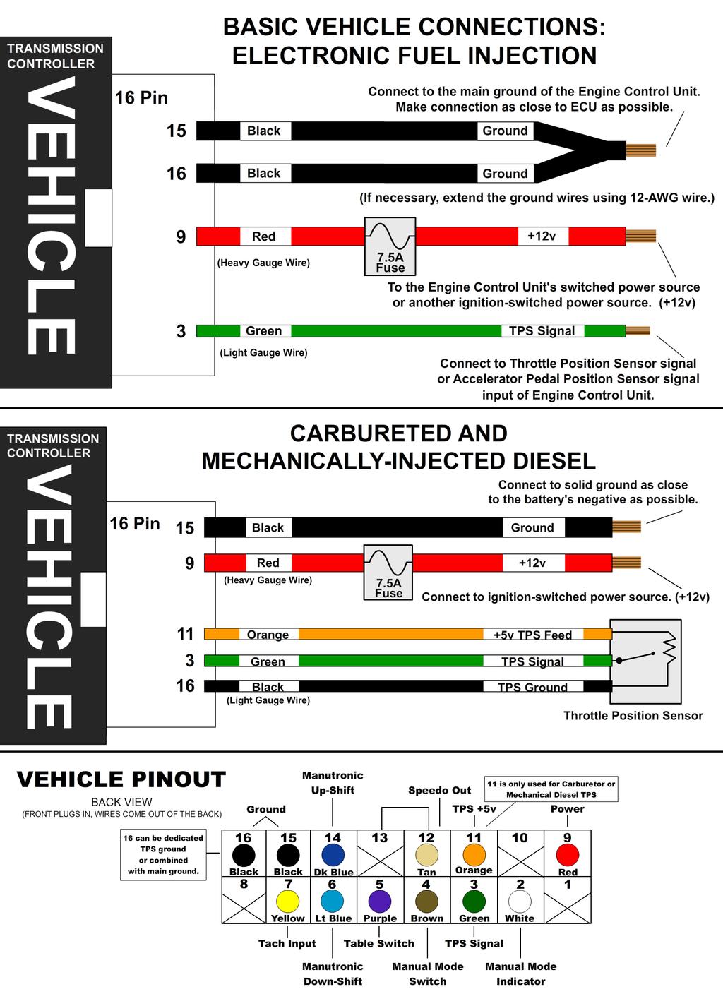
5 Step 1: Ground Splice the ground wires (Pins 15 & 16 Black) from the Quick 4 into the main ECU (Engine Control Unit) ground wire. Do NOT connect the ground wires to sheet metal or other ground sources. The Quick 4 MUST be connected to the Main ECU ground, as close to the ECU as possible. CONNECTING THE ESSENTIALS (ELECTRONIC FUEL INJECTION) Step 2: Power Splice the power wire (Pin 9 Red with 7.5 Amp fuse) from the Quick 4 into the main ECU (Engine Control Unit) ignition-switched power wire. Step 3: Throttle Position Sensor or Accelerator Pedal Position Sensor Splice the Throttle Position Sensor signal wire (Pin 3 Green) from the Quick 4 into the Throttle Position Sensor (TPS) signal input of the ECU (Engine Control Unit). If the vehicle has Electronic Throttle Control, use the Accelerator Pedal Position (APP) Sensor instead of the TPS. 5
 from the Quick 4 directly to the battery ground post or negative battery")

 from the Quick 4 to ignitionswitched power wire. Do NOT use accessoryswitched power.")

6 CONNECTING THE ESSENTIALS (CARBURETED AND MECHANICALLY-INJECTED DIESEL) Step 1: Ground Connect the ground wire (Pin 15 Black) from the Quick 4 directly to the battery ground post or negative battery cable. Do NOT connect the ground wire to sheet metal or other ground sources. The Quick 4 MUST be connected directly to the battery ground post or negative battery cable. Step 2: Power Connect the power wire (Pin 9 Red with 7.5 Amp fuse) from the Quick 4 to ignitionswitched power wire. Do NOT use accessoryswitched power. Step 3: Throttle Position Sensor Attach the 3 Throttle Position wires from the Quick 4 to the Throttle Position Sensor. Pin 16 Black is dedicated ground. Pin 11 Orange is +5v reference feed. Pin 3 Dark Green is the position sensor signal. See the "Throttle Position Sensor" section for details. 6
7 7


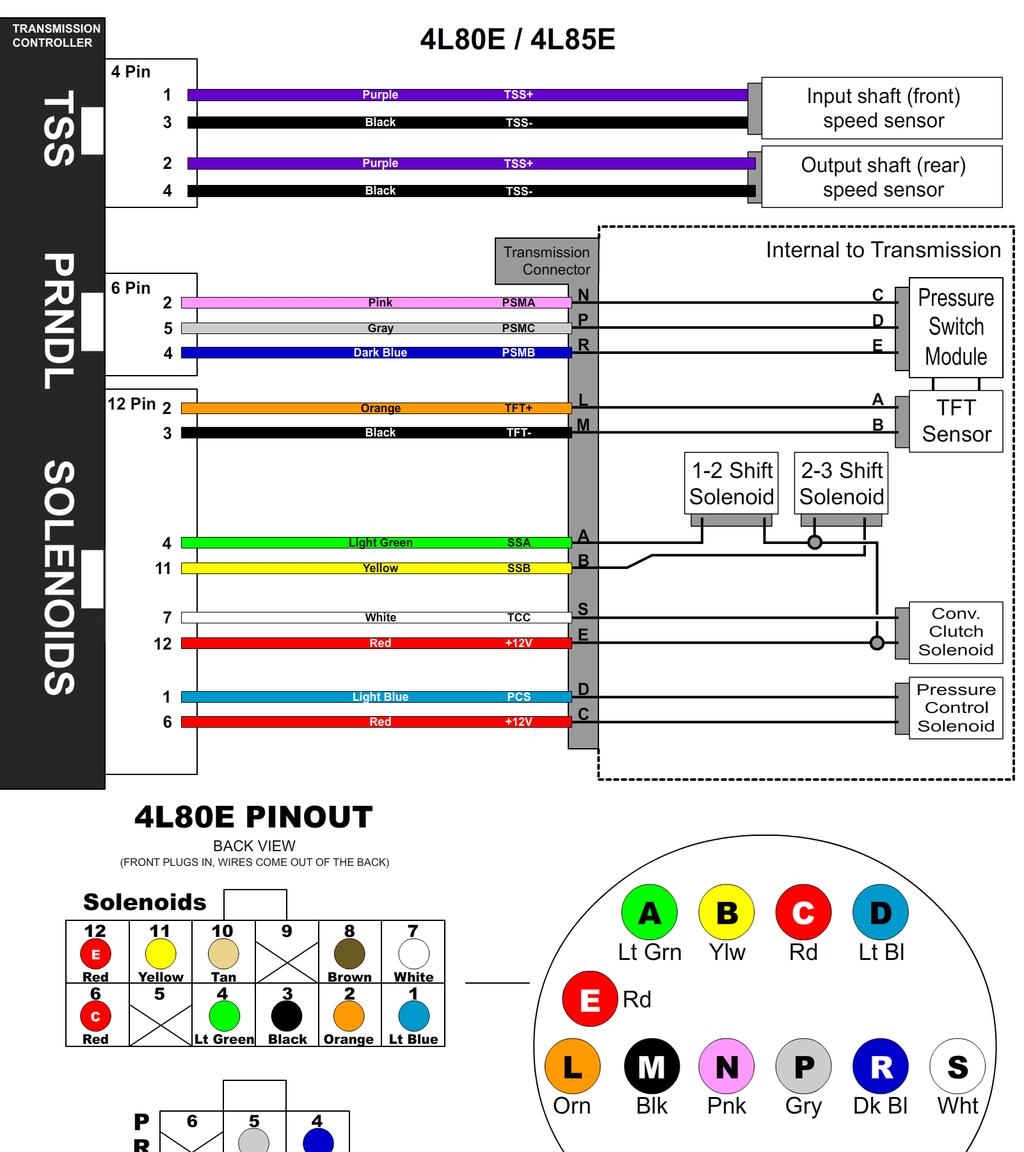
8 Step 4: Transmission Connectors Connect the Solenoid and TSS cables to the transmission. THE CONNECTORS MUST BE KEYED CORRECTLY for proper transmission operation (see the diagram below for details). Connect both TSS cables according to their labels. Additionally, connect the Neutral Safety Switch and the Backup Lamp Switch. The neutral safety switch isn t related to the Quick 4 controller or harness, but should be included in every installation. In some 4x4 transmissions, the output speed sensor may be missing or nonfunctional due to lacking a tone ring. You can use a speed sensor in the transfer case instead or install a 40 pulse tone ring in the transmission. A similar type of 40 pulse sensor may be used in transfer cases that do not have a mechanical speedometer drive. Step 5: Optional Features Connect any extra features you wish to use. See the "Optional Features" section for details. 8
9 SETTING UP THE QUICK 4 Step 6: Calibration For a detailed video walkthrough of the setup process, scan the QR code to the right using your smart phone. You can also find the video on USshift.com. Verify that the correct calibration is loaded on the Quick 4. A standard calibration specific to your order is loaded before shipment. However, if the transmission configuration has changed since the order was placed, you'll need to connect the Quick 4 to a Windows PC and install the Shiftware Tuning Software. (See the Shiftware section for installation instructions.) Using the software, load the calibration that matches your transmission's configuration. Step 7: Throttle Position Sensor Calibration Whether you have electronic fuel injection or a carburetor, you will need to set the throttle position. To do this, use the throttle position calibration option on the built-in tuning interface. When navigating the built-in tuning interface, use the knob to move through menu items and click to choose them. If you wait on an item, the long-form name will scroll across the screen. To calibrate throttle position, the ignition should be on but the engine not running. For carbureted engines, make sure the choke is fully open and off the fast idle cam before beginning. Turn the knob to SET (Set Up System) and click to enter the setup menu. TPS (Calibrate TPS) will be shown and you can click the knob again to enter calibration mode. It will begin detecting the idle throttle position right away, so leave the pedal untouched. When the display scrolls PRESS ACCEL PEDAL, push the accelerator pedal all the way to the floor and hold it. After a few seconds, RELEASE ACCL. PEDAL will scroll on the screen and you can release the pedal. TPS SUCCESSFUL will scroll if the setting completed. Afterward, it will show the measured closed and full throttle voltages. If an error occurs during calibration, the display will show the error and abort calibration. If this happens, you can try running the calibration again. If errors continue, you may need to check your wiring for problems. 9
10 Once the TPS calibration procedure is completed, the values are permanently stored in the controller and will be active for every tune written. TPS values displayed within individual tunes are then irrelevant. If you require TPS customization for individual tunes or are using a negative slope TPS, then the TPS values stored in the controller can be reset by double-clicking the knob while in TPS calibrate mode, causing the "TPS reset" message to be displayed. Our provided tuning software can then be used to calibrate TPS values for specific tunes. Possible TPS Calibration Errors as shown on the built-in display: ACCEL PEDAL NOT PRESSD / ACCEL PEDAL NOT HELD The throttle wasn t pushed or held at maximum long enough for the test to complete. Accelerator pedal must be held for 3 seconds and voltage must not drop more than 0.168V below the maximum recorded value. ACCEL PEDAL NOT RELEASED The throttle wasn t released within 5 seconds. The voltage must drop at least 0.96V below the maximum measured WOT value. TPS NOT STABLE The idle throttle position has changed values too drastically over the course of the calibration. The idle voltage is more than 0.6V greater than the lowest recorded value. ERROR TPS LO = 0.00 The voltage is below the minimum allowed 0.2V during any of the tests. 10


11 NOTES ON INSTALLATION If any error messages or unexpected characters are displayed, refer to the troubleshooting section at the end of this manual for detailed explanations. General Installation The Quick 4 unit should be mounted within the passenger compartment of the vehicle in a protected location. Good mounting areas include under the dash, behind a kick panel, or under the seat, as long as the unit and wiring are not subject to damage. Under-hood mounting is NOT possible with the Quick 4 unit. It is not waterproof or rated for under-hood temperatures. Passenger compartment mounting is also necessary to provide easy access to the USB port, which is used to interface with a PC for programming and diagnostics, as well as the display and function control knob. For this reason, be sure to mount the unit in a way that gives easy access to the USB port, knob, and display. If you will be using a desktop PC for programming, install the unit so that it can be unplugged and moved easily. All electrical connections should be made using 60/40 rosin core solder. Cover the connection with heat-shrinkable tubing for improved insulation and mechanical strength. Individual connector terminals can be connected using a piggy-back method, where the terminal is removed from the plastic connector housing to allow the new wire to be soldered on to the terminal atop the original wire. Two wires may be connected together by twisting them together longitudinally, soldering, then covering with the appropriate size heat-shrink tubing. Before Driving the Vehicle Start the engine and move the shifter through all positions, ensuring that the gear position and all sensor readings shown on the controller are correct. Most importantly, make sure that no error messages are shown on the Quick 4 display. It is a good idea to periodically check the Quick 4 display for errors as you drive, so it is wise to consider an accessible mounting location. If possible, perform a line pressure check to ensure that line pressure is correct at idle (typically 60-80PSI), and that it smoothly increases toward maximum (typically PSI) as the throttle position increases. If you have any questions about the installation or line pressure readings, please contact our technical support department. 11
12 Adaptation for Factory-Equipped Transmissions It is possible to use the Quick 4 controller in a vehicle which was originally equipped with one of the intended transmissions. This could be done in conjunction with an engine management system upgrade that no longer supports the transmission. Use of the controller for this purpose allows flexibility in choosing the engine management system, in addition to the increased control, performance, and transmission durability afforded by Quick 4. If you retain the stock PCM/VCM, it can probably be modified or re-flashed to disable the transmission functionality. Identifying the Terminals of an Unknown Throttle Position Sensor This is a procedure for identifying the correct terminal connections of any potentiometer-style throttle position sensor (almost all three-terminal TP sensors). A DVOM or analog Ohmmeter is required. 1. Set the meter to resistance mode and set it to a scale that can read up to 10K or 20K Ohms (if it is not auto-ranging). Please keep in mind when setting up and reading the meter that "K" means thousands of Ohms. In other words, 15K Ohms is the same as 15,000 Ohms. 2. Connect the meter to two pins at a time while operating the lever or cam of the TPS. Watch the meter while rotating the sensor. Check all three pairs of pins until you find a pair that does not change resistance when you rotate the sensor. The two pins that do not change resistance are the fixed ends of the resistance element (+5V and ground). The remaining pin that did change is known as the "wiper". It is the moving contact that slides along the resistance element to give the varying voltage. This is the output terminal of the sensor and should be connected to our green wire (Vehicle pin 3). 3. Next, with the sensor at the idle or closed throttle position, measure the resistance between the wiper (output) and each of the end terminals (the two whose resistance did not change in step 2) of the sensor. The end terminal with the lowest resistance to the wiper (at idle) is the ground terminal, and should connect to the black main ground wire of the controller (Vehicle pin 16). The terminal with the higher resistance to the wiper is the 5 volt reference input to the sensor and should connect to the orange wire (Vehicle pin 11) in our harness. General Guidelines for setting up Throttle Position Sensors The linkage to a throttle position sensor should use most of the rotating range of the throttle position sensor. This can be adjusted by changing the ratio of the linkage. Also, please make sure that a small amount of the sensor's travel is being used at idle. You will want a TPS voltage at idle of at least 0.35 volts. This is done to allow the controller to detect problems with the TP sensor. For instance, if the sensor becomes disconnected or the linkage falls off, the TPS voltage will fall below the set idle threshold. If the TPS voltage goes below the idle threshold, the controller assumes that the TPS is bad and will switch to failsafe line pressure and default shift points. This is done to prevent damage to the transmission from low line pressure and will provide a safe "limp home" mode. 12
13 TRANSMISSION DIAGRAMS 13

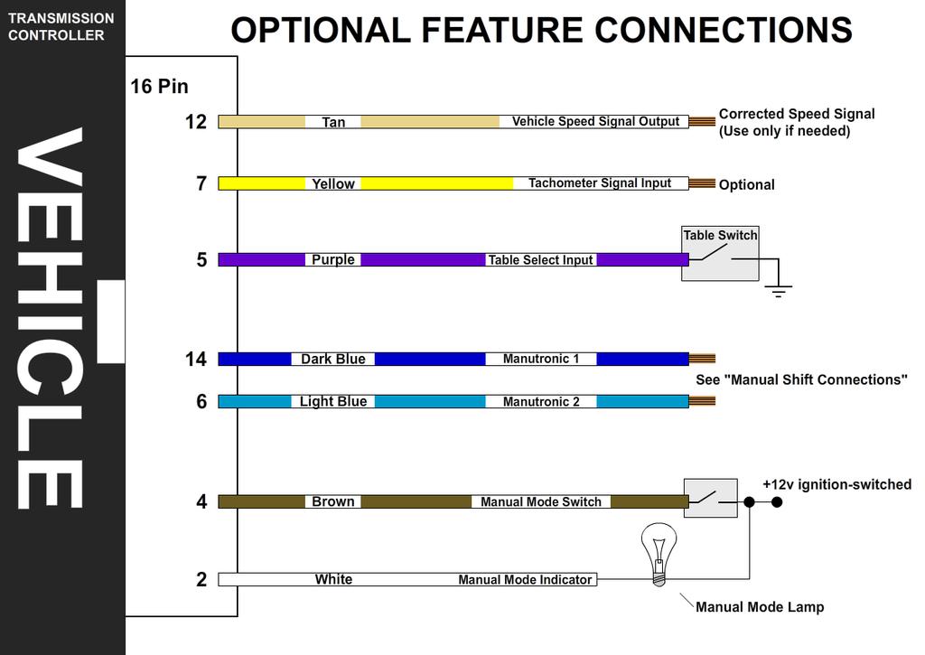
14 OPTIONAL FEATURES Multi-Tune This feature allows completely different calibrations to be used for the transmission at any time. The table selection switch can be a latching type switch (maintained toggle switch, latching push-button, etc.) or a momentary type switch (spring-loaded push-button switch, spring-loaded toggle switch, etc.) which applies ground to the table select input at Vehicle connector pin 5 when turned on. When a latching switch is used, it can only be used to switch between two tables. When the latching switch is activated, the controller will use the secondary calibration table (normally table 2), and it will run off of the primary table (normally table 1) when the switch is off. A momentary switch will cycle through all of the tables in use ( ). The Table Selection input may also be connected to a nitrous oxide system to provide an alternate calibration for use when the nitrous system is engaged. Other uses for this input include a Sport/Economy switch or a Normal/Aggressive switch. Whenever the table state is changed, it will be scrolled on the controller s display (tb1, tb2, tb3, tb4). There are alternative table select input methods that can be used. You can single-click the controller knob while at the status screen or attach a latching or momentary switch to the brown wire (pin 4). This would free up the purple wire (pin 5) to be a low-range selection switch. Different modes can be selected in the tuning software which will select different tables for different situations. For example, Select Tables Using Only 4WD Mode will use table 1 in 2WD and 4WD high range, with table 2 for 4WD low range (Tables 3-4 will be used for the second and third low ranges, if equipped) If a switch is connected to the table select wire, Select Tables Using Switch and 4WD Mode chooses tables 1 or 2 in 2WD mode and table 3 or 4 in 4WD (depending on switch position). Select Tables Using Manual Mode Status will choose the table according to whether manual mode is enabled or not. Auto mode will use table 1 and Manual mode will use table 2. (Table 3 and 4 will go unused.) 14
15 4x4 Low Range Detection Low range detection can be enabled if you want the controller to switch to an alternate calibration table when 4x4 low range is engaged. Configure the options in Shiftware under the 2WD/4WD Options and Table Select tabs in the settings window. For example, 4x4 low range detection can be enabled so that when ground is applied to pin 5 (purple) of the vehicle harness, the controller will switch to table 2. Another option includes single-clicking the controller knob to enable 4x4 low range calibration. Up to 3 low range ratios can be used. Whenever 4x4 low-range state is changed, it will be scrolled on the controller s display (4HI, 4Lo, 4L2, 4L3). Speedometer Output We have provided an adjustable speed signal output on the tan wire on pin 12 of the vehicle connector that can be used to drive an electronic speedometer, if desired. Use of this output signal is not necessary, but it can be helpful if your speedometer can not be driven correctly from another source. This signal can also be corrected for different gear ratios and tire heights, so it can be very useful in some applications. The speedometer output signal is normally provided as a 5 Volt square wave, but it can also be configured to provide a 12 Volt square wave when required. For more information, see the Jumper Settings document on USshift.com under Support / Manuals & Publications. There are two speedometer output modes that can be selected via the tuning software or the built-in tuning interface. It can also be disabled if not used. In the replicated speed sensor output mode, the speedometer output provides an amplified and squared version of the original speed sensor signal. Replicated mode is useful for applications that require a signal with the exact pulse rate of the speed sensor being used. There is also an adjustable corrected mode, which is very useful for correcting speedometer errors or providing unusual speedometer output signal frequencies. Adjustable mode is essentially the electronic equivalent of a ratio corrector gear box for a mechanical speedometer. In adjustable mode, the correction factor is entered as a decimal number. The correction factor is the frequency ratio of the speedometer output frequency to the speed sensor frequency. This number can be easily adjusted to synchronize the vehicle speedometer to a GPS or other instrument. 15
16 In some cases, such as driving the input of an engine control ECU, the 0-5 Volt (or 0-12 Volt) square wave signal will not be able to properly drive the device that it is connected to. This is because some devices are only designed to accept an input signal from a variable reluctance (magnetic coil) sensor. Because of this, they may expect the input signal to swing below ground (0 Volts). To drive this type of input, use the included capacitor to "offset" the DC value of the speedometer signal to 0 Volts. As a result, the driven device will see a -2.5V to +2.5V signal instead of 0V to 5V. To make this signal work, install the provided 10µF, 25v, non-polar, electrolytic capacitor inline between the speedometer output of the Quick 4 and the device that it is driving. To install the capacitor, cut the speedometer output wire and solder a capacitor lead to each of the two cut wires. Tachometer Signal Input The tachometer input can be connected to a digital tachometer output from an engine computer or the tachometer output from an MSD ignition or similar CDI (Capacitive Discharge Ignition) system, but NEVER to the coil outputs of a CDI system like MSD. For breaker points (or conventional electronic ignition systems such as GM HEI, Ford Duraspark or TFI), it can be connected to the coil negative terminal. For COP (Coil on Plug) ignition systems that do not have a conventional tachometer output (such as later Mustang engines), one of the coil trigger wires can be used, but the update rate will be slow. A better approach for such applications would be to use a tachometer adapter such as the AutoMeter Manual Mode Switch The Manual Mode switch can be used to turn manual gear selection on or off. The switch can be a latching switch (toggle switch, latching push-button, etc.) or a momentary type switch (spring-loaded push-button switch, spring-loaded toggle switch, etc.) connected to +12v ignition-switched power and pin 4 (brown) of the vehicle harness. (The tan wire on pin 12 is for VSS output and shouldn t be confused with the brown wire on pin 4 for the manual mode switch.) A momentary switch is needed to use more than 2 states. Optionally, you can add a light bulb between +12v ignition-switched power and pin 2 (white) of the vehicle harness. This lamp will normally light up when manual mode is on. Also, without adding a switch, a single-click of the controller s knob can turn manual mode on and off. This setting can be configured under the Flex-Shift tab of the tuning software and Dual Mode Auto / Manual Range Assignments is chosen from the pull-down menu. Whenever the Manual Mode state is changed, it will be scrolled on the controller s display (Auto, 321, 4321). 16
, connect the cathode (-) lead to the white wire on pin 2 of the vehicle harness and the anode (+) lead to +12v")
17 The FLEX-SHIFT Settings window. Auto/Manual settings are at the bottom. To use an LED bulb for the manual mode light (without built-in resistors for 12v), connect the cathode (-) lead to the white wire on pin 2 of the vehicle harness and the anode (+) lead to +12v ignition-switched power. Put a resistor in series on either side. We recommend using a 1.2k Ohm resistor, but you can use one with a lower resistance to make the LED brighter or one with a higher resistance to make it dimmer. It s best to stay above 1k Ohm to protect the LED. A 1/4w resistor or higher is recommended. 17
18 18

19 MANUAL SHIFT CONNECTIONS Manutronic Overview If connected and enabled in the software, the ManuTronic feature will allow manual selection of all forward gears using paddles, buttons, or another type of switch. With ManuTronic engaged, a brief press of the UPSHIFT button will change to the next higher gear, while DOWNSHIFT will change to the next lower gear. ManuTronic also has a safety feature which inhibits downshifting if the engine RPM is too high, which prevents over-revving of the engine due to a driver's error. Manutronic Reference Supply (JW2-5) There are several different ways to configure the Manutronic to meet your specific needs. Depending on your Manutronic configuration, you may need to install or uninstall the Manutronic jumper (JW2-5). For more information, see the Jumper Settings document on USshift.com under Support / Manuals & Publications. This jumper supplies 5V to the Manutronic 1 input and should be installed for all Manutronic configurations (except for a Ford cruise control system). See the sections below for further explanation. 19
 to your up-shift button (momentary).")
20 Momentary Shift Buttons with Latching On / Off Switch For this configuration, you will need to connect the Dark Blue wire (Pin 14 on the Vehicle Connector) to your down-shift button (momentary) and connect the Light Blue wire (Pin 6 on the Vehicle Connector) to your up-shift button (momentary). To connect the on / off switch (latching), solder the switch's wire onto the Dark Blue down-shift wire with a 680 Ohm resistor between them. (Follow the guidelines for soldering found in the General Installation section.) Remember that the Manutronic jumper must be installed in the Quick 4 controller and the correct settings used in the Shiftware setup. Manutronic will be enabled when the toggle switch is turned on and disabled when it is turned off. 20
 to your up-shift button (momentary).")
21 Momentary Shift Buttons with Momentary On / Off Switch For this configuration, you will need to connect the Dark Blue wire (Pin 14 on the Vehicle Connector) to your down-shift button (momentary) and connect the Light Blue wire (Pin 6 on the Vehicle Connector) to your up-shift button (momentary). To connect the on / off switch (momentary), solder one side of the switch onto the Dark Blue down-shift wire and the other side to the Light Blue up-shift wire. (Follow the guidelines for soldering found in the General Installation section.) Remember that the Manutronic jumper must be installed in the Quick 4 controller and the correct settings used in the Shiftware setup. To enable the Manutronic, press the On/Off button once and do the same to disable it. 21
 to COM1 of the receiver. You can use either a momentary push-button on / off switch or a latching toggle on / off switch.")
22 Twist Machine Shrifter TM For this configuration, you will need to connect the Dark Blue wire (Pin 14 on the Vehicle Connector) to COM2 of the receiver and connect the Light Blue wire (Pin 6 on the Vehicle Connector) to COM1 of the receiver. You can use either a momentary push-button on / off switch or a latching toggle on / off switch. (Refer to the previous two sections on how to install and use the on / off switch.) Remember that the Manutronic jumper must be installed in the Quick 4 controller and the correct settings used in the Shiftware setup. 22


23 BUILT-IN DISPLAY The built-in Quick 4 User Interface allows most sensor values to be viewed, while also allowing the transmission to be manually shifted. With firmware version or later, self-contained, initial setup and basic tuning of transmission settings is also possible via the tuning menu. In addition, a computer running our included tuning software can be connected to provide advanced tuning options (see Shiftware section). MAIN MENU In the main menu, the three letter mode name is shown on the display first. Then, the long-form name will scroll across the screen. After the name scrolls, the value for that item will be shown. You can repeat the name of most items by pressing the function knob, other than "Status", "Setup" and Tuning modes. Display Off In this mode the display is blank and nothing is shown. StA = Status This mode is the default display mode. The first character indicates the selected transmission range (P, r, n, o, d, 2, 1). or "E" if there is an error with the PRNDL switch (range sensor or pressure switch module). The second character is normally blank, but will show "P" if Manutronic Pushbutton shift mode is active or an "L" if Dyno Test mode is active. The third character indicates the currently commanded or selected transmission gear. There is also a small dot at the upper-left-hand corner of the third display character (similar to an apostrophe). This dot will illuminate when the torque converter clutch is engaged. dyn = Dyno Test In status mode, double-clicking the function knob will activate or deactivate Dyno Test mode. When activated, dyno test will scroll for 2.5 seconds, then return to the status screen with the addition of an "L" in the center of the display. This mode enables manual gear selection and prevents unwanted up and downshifts. This is for diagnostic use and for commanding a specific gear while operating your vehicle on a dynomometer. No additional connections or configuration options are required to use dyno test mode and the desired gear can be selected by rotating the function knob clock-wise to up-shift or counterclockwise to down-shift. 23
24 Torque converter clutch engagement can be commanded with a single-click of the function knob while in Dyno mode. The "L" in the center of the display will change to a "t" when the converter clutch has been manually engaged. Another single-click of the function knob will turn converter clutch engagement off. We have programmed a safe, minimum engine RPM into the controller, and converter clutch engagement will not occur, even if manually commanded, until this engine speed is reached. (In pre-v5.6 firmware, this will be "SEL" instead of "dyn", which is simple gear selection without the torque converter clutch control features of Dyno Mode.) AUt = Automatic Select Indicates that you have left Dyno Test mode and are back in automatic transmission mode. When in Dyno Test mode, double-click the function knob to return to automatic mode. AUT will be displayed for 2.5 seconds, then return to the normal status screen. SPd = Road Speed Indicates vehicle speed (from the output shaft speed sensor or vehicle speed sensor) in MPH. (KPH if the metric system is selected in the system settings of the tuning software.) tps = Throttle Position Indicates throttle position sensor value in volts. ºF/ºC = Transmission Fluid Temperature Indicates current transmission fluid temperature in degrees Fahrenheit (or Celcius if using metric). The degree symbol is represented on the display by a raised lower-case "o". tac = Engine Tachometer Indicates engine RPM RPM is displayed as actual RPM. Above 1000 RPM will be displayed with a decimal. (2.30 = 2300 RPM) bat = Battery Voltage Indicates vehicle battery condition in DC volts. 24

25 PrS = Commanded Line Pressure Indicates the transmission line pressure that the controller is currently commanding in PSI. These values are based upon the normal OEM parameters for the pressure control solenoid and main regulator valve line-up for the selected transmission. The actual line pressure may vary from this value, especially if changes have been made to the main pressure regulator valve, the main regulator valve spring, the main regulator boost valve, or the pressure control (EPC) solenoid. tbl = Tune (Table) Selection Shows the currently selected table (TB1, TB2, TB3, or TB4) after showing "TbL" for 2.5 seconds. Pressing the knob once displays "SLT" for 2.5 seconds to show that the table can be manually selected. In select mode, you can rotate the knob to select "res", "tb1", tb2, tb3, tb4. res stands for "Remote Select" and indicates that the table is selected remotely by the table select input. Remote Select mode is the power-on default. You can select tables 1-4 to override the table select input and force the Quick 4 to use a specific table. Once you have selected the desired table or mode, you can exit select mode by pressing the knob once. "ret" will then be displayed for 2.5 seconds to indicate that you have returned from select mode. The selected mode will be retained until the ignition is turned off or until you change it. SEt = Set Up System The setup system menu allows you to easily make the required initial calibrations after installation. Press the knob once to enter the setup menu. The changes made in the menu take effect in real time and are saved to the tune calibration after exiting each item. See the Setup Menu section below for more information. tne = Tuning Settings Allows the most commonly-used settings (such as shift points and shift firmness) to be adjusted directly on the controller. Press the knob once to enter Tuning Mode. This mode allows you to make real-time adjustments to your tune calibration. See the Tuning Menu Options section below for more information. SrE = Software Revision ID Indicates the software and hardware revision of the controller. "MajorRev.MinorRev.HardwareRev" (ie: 4.1.3) 25
26 SETUP MENU OPTIONS All of these settings can be changed by entering "adjustment mode" (by pressing the knob once) and turning the knob clockwise to increase the setting or counter-clockwise to decrease it. Changes will be effective immediately and you can return to the setup menu by pressing the knob a second time. tps = Calibrate Throttle Position This is a required step before driving the vehicle for the first time. Clicking this item will begin the throttle position calibration. Follow the steps as they appear on the display. For more details on this procedure, see Step 7: Throttle Position Sensor Calibration on page 9. CLr = Clear Learning Clicking on this item will allow you to chose which learned data to clear. You might want to use this if something has changed with the vehicle or transmission to allow the controller to re-learn the data. The options are No, which exits without clearing anything, "TCC Learn", Shift Timing, and All. ret = Return Click this to return to the main menu. TUNING MENU OPTIONS All of these settings can be changed by entering "adjustment mode" (by pressing the knob once) and turning the knob clockwise to increase the setting or counter-clockwise to decrease it. Changes will be effective immediately and you can return to the tuning menu by pressing the knob a second time. The new settings will be saved to the current active tune when the return ("ret") option is displayed and the knob is clicked. If the ignition is turned off before "ret" is selected, the new changes will be lost. 1:2U, 2:3U, 3:4U = Full Throttle Upshift Speed This setting is used to adjust the full-throttle shift RPM for the chosen upshift. The RPM value is displayed in thousands (e.g = 5250 RPM). If you are in doubt, start on the low side. Press the knob once to enter the adjustment mode and change this setting. (Press once again to return to the menu.) 26 LtU = Light Throttle Upshift Speed This setting is used to adjust the light-throttle shift RPM for all shifts. The value shown is the approximate closed-throttle RPM for the 2-3 upshift and is displayed in thousands (e.g = 1320 RPM). The 1-2 and 3-4 shifts are scaled proportionally with the 2-3 shift RPM as it is changed. Press the knob
27 once to enter adjustment mode and change the setting. (Press again to return to the menu.) As the shift points are modified at either light or full throttle, the values in between are automatically scaled proportionally. The light throttle RPM adjustment has the greatest effect at closed throttle and the influence of this adjustment diminishes to zero as you approach wide-open throttle. The reverse is true for the full-throttle RPM adjustments. tcc = Torque Converter Clutch Engagement Speed This setting is the transmission input shaft RPM (1.70 = 1700 RPM) at which the torque converter clutch will engage (providing that all other conditions for engagement are met). Press the knob once to enter the adjustment mode to change this setting. (Press again to return to the menu.) 1:2F, 2:3F, 3:4F = Light Throttle Firmness This setting is used to adjust the light-throttle shift firmness for the chosen upshift. Value is in commanded line pressure (PSI). Higher values provide firmer shifts. This value should not be adjusted until after the shift points are set since the shift points affect shift feel. If you are in doubt, try higher values for this setting. Press the knob once to enter adjustment mode and change this setting. (Press again to return to the menu.) HtF = Hard Throttle Firmness This setting is used to adjust the heavy-throttle shift firmness for all upshifts in tandem. Value is in commanded line pressure (PSI). Higher values provide firmer shifts. This value should not be adjusted until after the shift points are set since the shift points affect shift feel. If you are in doubt, try higher values for this setting. Press the knob once to enter adjustment mode and change this setting. (Press again to return to the menu.) SPO = Speedo Out Configure Click the knob to enter adjustment mode. It will either display "OFF" (output disabled), "rep" (replicated speed sensor output), or a decimal number for adjustable output mode. Double-clicking the knob will change modes in the order of OFF, rep, then the correction factor (such as 1.25) for adjustable mode. Turning the knob will change the correction factor. The effect will immediately be visible on the vehicle's speedometer. ret = Return Saves the changes to the currently-selected table and exits to the main menu. If the ignition is turned off before "RET" is executed, your changes will be lost. 27
28 28
29 29
30 30

31 SHIFTWARE Introduction Using the Shiftware software allows you to modify the way your Quick 4 Transmission Control System behaves. You can customize shift-points as well as monitor and diagnose the Quick 4 unit in real-time. Setup To create a calibration for the Quick 4, it is best to start with one of the standard calibrations which are included with the software. To load a standard configuration for your transmission, click the Open button on the toolbar, then browse to the folder where the transmission calibration files are located. (Default location is C:\Shiftware\) The files are named according to the transmission and RPM range and have the.btc file extension. Choose the calibration file and click Open. Once the calibration file is loaded, click the System Settings button on the toolbar to check the settings and make sure that they are correct for your transmission. The System Settings window has several tabs within it. Click each one to see each section of settings specific for your transmission. The System Settings Window 31

32 Customize The main window is where all of the shift points and line pressure editing is done. The graph displays the up-shift and down-shift speeds in relation to throttle position for each shift. It also displays the line pressure & firmness curve in relation to throttle position. The line pressure curve is displayed in PSI, so the higher the curve, the more firm shifts will be. You can use the checkboxes on the right to turn on the curves for individual shift firmness and adjust them independently. The Main Window You can get help on anything by clicking the Question button (or the F1 key) and then clicking on an item. This can be used in any area of the software. The help messages in the settings pages are transmission-specific and are more like getting professional advice than normal help tips. The graph has ten points from left to right, 0 being idle and 9 being Wide-Open- Throttle (WOT). On the left side of the graph is the shift speed. When you hover over a graph point, you can also see the corresponding shift speed in RPM or the applicable unit values for items other than shift points. Click on a point in the graph to select it. 32
33 If Select Pairs Together is enabled, then the corresponding down-shift point will be automatically selected along with the up-shift point. This can be turned off by clicking the Select Pairs Together checkbox on the right. You can select multiple points by holding CTRL while clicking the points or a range of points by holding SHIFT and clicking the two points on each end. You can move between adjacent points using the LEFT and RIGHT arrow keys. Once a point (or points) is selected, you can drag it with the mouse to raise and lower its value. A yellow box will appear in the graph telling you what the value of the point is. Adaptive Learning By default, the Quick 4 will learn the shift and TCC timing characteristics of your transmission. It will complete a learning cycle over the first few hard-throttle passes and will use the learned data to optimize shifts. For learning to occur, the tachometer input signal must be connected and functioning properly. During the learning cycle, you may notice unusual TCC operation. This is normal and will end once learning is complete. Once learned, the data will not change unless it is erased using the clear (CLr) command on the controller s display. Clearing the data will cause another learning cycle to begin. For optimum accuracy, learning should be done at the same transmission fluid temperature that it will be run at during normal operation. Once learned, shift point accuracy will only be limited by the consistency of your transmission s valve body. If you wish to disable learning, enter Settings in the tuning software and switch to the Miscellaneous tab. Uncheck Enable Learned Shift Timing. This will stop the controller from using learned data, but will not erase the learned data. This would be useful if you plan to make changes to the transmission or are unable to complete a proper learning cycle. Save & Load Once you have created your calibration, you can save the file to your hard drive or an external storage device. To save, click the Save button on the toolbar. Then, browse to the location where you want it saved and click Save. Use Save As under the FILE menu to leave the original file unchanged and create a new version. Type the desired filename and click Save. Files are saved with a.btc extension. To load a calibration file, click the Open button on the toolbar. Then, browse to the file and click Open. 33
. Click the Write Calibration button on the toolbar and a menu will appear.")
34 Writing a Calibration to the Quick 4: For the changes you've made to take effect on the Quick 4 controller, you first must write the calibration to the unit. Connect the Quick 4 to your computer using a standard USB cord (Type A to Type B). Click the Write Calibration button on the toolbar and a menu will appear. If you aren t using multiple calibrations, click the All Tables button to save the calibration to the controller. The Quick 4 can now be disconnected from the computer and installed in the vehicle. (To use multiple tables, you can create a new calibration and choose one of the other table buttons when writing to the controller.) When the Quick 4 unit is disconnected from the computer, the Write Calibration button will be grayed out. IMPORTANT INFORMATION How to Avoid Errors The Shiftware software gives you complete freedom and flexibility to customize your shifting calibration however you want. This freedom requires diligence to avoid errors. It is very important that the up-shift and down-shift curves for a given gear do not cross. The up-shift point at any throttle position should usually be at least 15% greater than the down-shift point. For instance, if the 2-3 up-shift point at ½-throttle is 45MPH, then the 3-2 down-shift point should usually be less than 40MPH. The On-Off differential between up-shift and down-shift points is called Deadband (also known as Hysteresis). The more deadband you use for your shift points, the more stable the system will be. Not using enough deadband can result in erratic shift behavior. Too much deadband will result in sluggish behavior due to a reluctance to down-shift. Pay close attention to the interaction between different shifts. Overlapping the 1-2 and 2-3 shifts can cause skipped gears and other drivability problems. Also note that torque converter slip at low speeds renders engine RPM values meaningless. It is usually desirable to have light-throttle shift points within a low RPM range. In this case, it is best to base light-throttle shift points on vehicle speed rather than engine RPM (as most auto manufacturers do). 34
35 TROUBLESHOOTING ERROR MESSAGES WARNING! If the transmission does not begin to operate correctly within the first few feet of the road test, STOP immediately, check the troubleshooting guide, and call Baumann Electronic Controls if you need assistance. In some cases, just a few blocks of operation with low fluid pressure can destroy a transmission. Error Messages The following error messages will scroll on the controller's display when faults are detected. For more detailed error messages, you can also view the Controller Fault Display in the tuning software. The software is not limited to currently set faults, but can show fault history as well. History is cleared when the controller powers down completely (ignition turned off and USB cable removed from computer.) Error messages will not be shown while in tuning mode. It is a good idea to periodically check the display for errors as you drive, so it is wise to consider an accessible mounting location. Scan the QR Code to be directed to the corresponding troubleshooting guide webpage or visit t1x.us. Err. battery Lo The voltage to the controller has dropped below 8 volts. Err. battery HIgh The voltage to the controller is above 17.2 volts. Err. PSoL. CurrEnt HI An over-current condition was detected with the pressure control solenoid. The controller will attempt to disable the pressure control solenoid until the ignition is turned off. If this fault is detected, the vehicle should not be driven until it is corrected. If you must drive with this failure, it is recommended that you disconnect power from the system by removing the 7.5A fuse to insure that the transmission will stay in default mode regardless of any wiring problems that may exist. Err. PSoL. CurrEnt Lo Current measured in pressure control solenoid was too low. 35
36 Err. SoL.1 CurrEnt HI (Can be solenoid 1-3) An over-current condition was detected with one of the solenoid banks. The solenoids on bank 1 include shift solenoid B (or 2) and the second TCC (ON/OFF) solenoid (GM 4L60E transmissions only). The solenoids on bank 2 include shift solenoid A (or 1). The solenoids on bank 3 include the TCC PWM solenoid and the 3-2 downshift control solenoid (GM 4L60E transmissions only). The controller will attempt to disable the solenoid bank with the over-current condition until the ignition is turned off. Err. SoL.1 CurrEnt Lo (Can be solenoid 1-3) Current measured in solenoid bank (1-3) was too low. Err. TPS Lo-run SEtuP The Throttle Position Sensor is in fault mode due to the voltage being below the idle threshold value that was set. Run TPS calibration in the setup menu. Err. TFT Short The TFT sensor voltage is too low. A possible cause of this could be that it is shorted to ground. Err. TFT OPEn The TFT sensor voltage is too high. The TFT sensor circuit could be open. Err. trans Hot The temperature in the transmission is above the allowed threshold (which can be adjusted in the tuning software). Err. OSS FAILure The Output Shaft Speed Sensor is open or missing. Err. ISS FAILure The Input Shaft (Turbine) Speed Sensor (if equipped) is open or missing. Err. tbl1 Corrupt (Can be table 1-4) A Checksum error has been found in the table corresponding to the number shown. (On Quick 6, this error will force a hard failsafe mode until it is fixed.) It will also disable saving Setup Menu changes for the bad table and disable the tuning menu for the bad table. Connect the controller to a PC and load a calibration using Shiftware. 36
37 Err. tcc SLIP Torque converter clutch slip detected when fully engaged. Err. TrAnS. SLIP Transmission appears to be slipping in at least one gear. Err. FULL PrESS. SLIP Transmission continued to slip after maximum line pressure was commanded. Err. repeatd. SLIP Transmission slip was detected more than twice in this drive cycle (max. line pressure latched). Err. ratio High Transmission gear ratio appears to be too high in at least one gear. Err. PrndL out of range Sensor voltage or duty cycle out of tolerance limits, but within approximate range. Err. PrndL SIgnAL Lo Sensor voltage or duty cycle low. Err. PrndL SIgnAL HIgH Sensor voltage or duty cycle high. Err. no PrndL SIgnAL PWM signal for range sensor not detected. Err. bad PrndL=XX-XX DTR or PSM signal combination not valid. XX-XX indicates high/low status of all 4 DTR pins (1 or 0) Err. Ford dtr Lo Voltage from 270 Ohm resistor in Ford DTR sensor measures too low. Err. Ford dtr HIgH Voltage from 270 Ohm resistor in Ford DTR sensor measures too high. 37
38 Err. Clutch Learn Applies to Quick 6 only. The clutch learning data is either corrupt or missing. Run the clutch learning procedure from the SETUP menu. See page 40 for details. SHiFt SOLx SHOrted Shift Solenoid X resistance measured too low during the power-on solenoid check. (X identifies solenoid A F.) SHiFt SOLx OPEn Shift Solenoid X resistance measured too high during the power-on solenoid check. (X identifies solenoid A F.) PrESS SOL. SHOrted Line Pressure Control Solenoid resistance measured too low during the poweron solenoid check. PrESS SOL. OPEn Line Pressure Control Solenoid resistance measured too high during the poweron solenoid check. TCC SOL. SHOrted Torque Converter Clutch Control Solenoid resistance measured too low during the power-on solenoid check. TCC SOL. OPEn Torque Converter Clutch Control Solenoid resistance measured too high during the power-on solenoid check. Err. HI SIdE dr. SHOrted The high-side output driver appears to be shorted on. Contact Baumann Electronic Controls technical support for assistance. Err. Lo SIdE dr. SHOrted A low-side output driver appears to be shorted on. Contact Baumann Electronic Controls technical support for assistance. Err. CurrEnt SEnSE Measured low-side and high-side currents do not match. Contact Baumann Electronic Controls technical support for assistance. 38
39 CONTACT If you have any questions, problems, or product orders, don t hesitate to call our customer service line. (864) (Monday-Friday 10AM-6PM EST). If no one is available, please leave a detailed message and we will reply promptly. Whenever possible, we will try to return urgent technical support calls left after hours or over the weekend. You can also customer service at support@usshift.com Scan this code to copy the customer service phone number and address to your phone. 39
Installation and Operation Manual for 4R70W, 4R75, and AOD-E Transmissions
 Installation and Operation Manual for 4R70W, 4R75, and AOD-E Transmissions US Shift Transmission Control System instruction and operation manual. www.usshift.com Baumann Electronic Controls, LLC. Phone:
Transmission electronic controls outline. Inputs- processing- outputs
 Transmission electronic controls outline Inputs- processing- outputs Inputs provide the system the environmental conditions that are needed to operate or check the operation of the transmission. Inputs
Dodge Neon SRT-4 N2MB WOT Box Installation Instructions
 Dodge Neon SRT-4 N2MB WOT Box Installation Instructions NOTE: If you have a CDI (capacitive discharge ignition system) please contact us at support@n2mb.com for additional instructions. Damage to your
WIDE OPEN THROTTLE/ RPM ACTIVATED 2 STAGE WINDOW SWITCH WITH SHIFT LIGHT CONTROL
 WIDE OPEN THROTTLE/ RPM ACTIVATED 2 STAGE WINDOW SWITCH WITH SHIFT LIGHT CONTROL Kit Number 15982NOS OWNER S MANUAL P/N 199R10482 CONGRATULATIONS on purchasing your NOS WOT/Window Switch! It should provide
MAX ENERGY POWER PROGRAMMER PART #52001/52501 REFERENCE GUIDE AND INSTALLATION MANUAL ADDENDUM 2007-2010 JEEP WRANGLER WITH ENHANCED OFF-ROAD FEATURES
 MAX ENERGY POWER PROGRAMMER PART #52001/52501 REFERENCE GUIDE AND INSTALLATION MANUAL ADDENDUM 2007-2010 JEEP WRANGLER WITH ENHANCED OFF-ROAD FEATURES The following is a step by step guide for installing
PUSH BUTTON START INSTALLATION MANUAL
 PUSH BUTTON START INSTALLATION MANUAL ALTHOUGH THIS PRODUCT HAS BEEN THOROUGHLY TESTED KPIERSON TECHNOLOGIES ASSUMES NO RESPONSIBILITY FOR ANY DAMAGE THAT MAY RESULT BY THE INSTALLATION OF THIS PRODUCT.
VEHICLE SPEED CONTROL SYSTEM
 PL VEHICLE SPEED CONTROL SYSTEM 8H - 1 VEHICLE SPEED CONTROL SYSTEM TABLE OF CONTENTS page DESCRIPTION AND SPEED CONTROL SYSTEM...1 SPEED CONTROL SERVO-PCM OUTPUT....2 SPEED CONTROL SWITCHES PCM INPUT...2
Universal TCC Lock-Up Kit for 700R4 and 2004R
 TCI 376600 Universal TCC Lock-Up Kit for 700R4 and 2004R This kit enables hands-free, automatic activation of the Torque Converter Clutch (TCC) along with the option of manual control. TCI 376600 Kit Contains:
2-Stage Progressive Switch INSTALLATION AND USER MANUAL. KWS0020 rev E
 2-Stage Progressive Switch INSTALLATION AND USER MANUAL i Table of Contents Page 1. Overview...1 2. Software Installation...1 3. Configuration...2 3.1 Throttle Position Sensor (TPS) Input...2 3.2 RPM Input...3
WOT Box Installation Instructions VW GTI MKV 2.0T
 WOT Box Installation Instructions VW GTI MKV 2.0T Connector Pinout Pin Color AWG Name Description 1 Yellow 18 IG #1 Connect to Ignition Coil #1 Trigger Signal VIOLET / GRAY 2 Black 18 Ground Connect to
Electronic Power Control
 Service. Self-Study Programme 210 Electronic Power Control Design and Function With the Electronic Power Control system, the throttle valve is actuated only by an electric motor. This eliminates the need
TOYOTA ELECTRONIC TRANSMISSION CHECKS & DIAGNOSIS
 Checks and Adjustments The transmission requires regular maintenance intervals if it is to continue to operate without failure. As we discussed in previous sections, transmission fluid loses certain properties
INSTRUMENT PANEL. 1995 Volvo 850 DESCRIPTION & OPERATION. 1995-96 ACCESSORIES & EQUIPMENT Volvo Instrument Panels
 INSTRUMENT PANEL 1995 Volvo 850 1995-96 ACCESSORIES & EQUIPMENT Volvo Instrument Panels 850 WARNING: When working around steering column and before performing repairs, disconnect and shield battery ground
well as pulses from a magnetic driveshaft sensor or a magnetic speedometer cable sensor.
 1. Overview The Maximizer 4 progressive nitrous controller operates one or two separate stages of nitrous based on either time, RPM, MPH, throttle percentage or boost pressure. Whether your engine is naturally
INSTALLATION INSTRUCTIONS BOOST CONTROLLER. Pro Control Input (Optional) Tach. Signal. Speed. Gray. Signal. Green Blue. Orange.
 Tach. Signal. Speed. Gray. Signal. Green Blue. Orange.") 2650-1706-00 INSTALLATION INSTRUCTIONS BOOST CONTROLLER WARNING! The installation of the Auto Meter Boost Controller is recommended only for experienced technicians. This product may damage your engine
2650-1706-00 INSTALLATION INSTRUCTIONS BOOST CONTROLLER WARNING! The installation of the Auto Meter Boost Controller is recommended only for experienced technicians. This product may damage your engine
Section 55 Chapter 3
 Section 55 Chapter 3 HITCH CONTROLLER Calibration and Fault Codes 6-12850NH TABLE OF CONTENTS HITCH CONTROLLER CALIBRATION... 55-4 Setup Process... 55-4 Requirements For Calibration... 55-4 Hitch Setup
Asian Warner 55-50SN Seminar
 General Description Asian Warner 55-50SN Seminar This transmission is manufactured by Asian Warner. It can be found in many different vehicles such as General Motors, Volvo, Saab, Renault and Fiat. Although
MDC Cruise Control Instructions
 1 MDC Cruise Control Instructions Please read the installation manual thoroughly before performing installation of the cruise control. Do not bypass reading the manual prior to installation as you may
Contents Installing the ucal Software on your PC/Laptop ucal Programmer Version Connecting the ucal Programmer to your PC/Laptop
 Contents Installing the ucal Software on your PC/Laptop 1 ucal Programmer Version 1 Connecting the ucal Programmer to your PC/Laptop 1 Optional USB Adapter Kit (for ucal) 1 Installing the USB Driver for
AMS-1000 Multi-Channel Air Management System for Boost Control
 AMS-000 Multi-Channel Air Management System for Boost Control The terminal pin descriptions may also be viewed on screen. See Page 4 of manual for details. Clutch Input Shift Input Scramble Boost Input
Wiring Your Megasquirt (MS):
:") Wiring Your Megasquirt (MS): 1.6L: Your ECU is located under the passenger foot rest. Remove the side sill with a Phillips head screw driver and pull the carpet back, the cover can be lifted off after
Wiring Your Megasquirt (MS): 1.6L: Your ECU is located under the passenger foot rest. Remove the side sill with a Phillips head screw driver and pull the carpet back, the cover can be lifted off after
FREIGHTLINER CUSTOM CHASSIS CORPORATION TRAINING SESSION M-LINE INSTRUMENT PANEL
 FREIGHTLINER CUSTOM CHASSIS CORPORATION TRAINING SESSION M-LINE INSTRUMENT PANEL Page 2 Freightliner Custom Chassis Corporation Technical Service Guide for M-Line Instrument Clusters GENERAL INFORMATION
Signature and ISX CM870 Electronics
 Signature and ISX CM870 Electronics Cummins West Training Center System Description General Information The Signature and ISX CM870 engine control system is an electronically operated fuel control system
Electronically Controlled Air Suspension (ECAS) for Trucks
 for Trucks") $2.50 Electronically Controlled Air Suspension (ECAS) for Trucks Maintenance Manual No. 36 Issued 7-99 ECAS System for 6 x 2 and 6 x 4 Vehicles with Rear Air Suspensions Service Notes Service Notes This
$2.50 Electronically Controlled Air Suspension (ECAS) for Trucks Maintenance Manual No. 36 Issued 7-99 ECAS System for 6 x 2 and 6 x 4 Vehicles with Rear Air Suspensions Service Notes Service Notes This
ELECTRONIC THROTTLE CONTROL SYSTEM
 80 ELECTRONIC THROTTLE CONTROL SYSTEM Figure 80-1 The throttle pedal is connected to the accelerator pedal position (APP) sensor. The electronic throttle body includes a throttle position sensor to provide
STM-100 Data Bus Breakout for Harley Davidson models
 STM-100 Data Bus Breakout for 2004 2010 Harley Davidson models The STM-100 can be used to simplify the installation of an aftermarket speedometer and/or tachometer on a 2004 2010 Harley Davidson motorcycle.
1 RELAY / 4 BUTTON SERIES
 BW2450.qxd 6/11/2009 4:12 PM Page 1 1 RELAY / 4 BUTTON SERIES VEHICLE SECURITY SYSTEM Button 1 Button 2 Button 3 Button 4 Transmitter styles may vary Standard Features: Two 4-Button Remote Transmitters
Electronic Throttle Control Systems
 Section 7 Electronic Throttle Control Systems Limp Mode Lever Throttle Valve Throttle Position Sensor Acceleration Pedal Position Sensor Throttle Control Motor Magnetic Clutch T852f275 Lesson Objectives
If it s not Allison, it s not Automatic.
 SHIFT SELECTOR OPERATION AND MANUAL How to use the shift selector to read oil level and diagnostic codes on 3000/4000 Series Allison transmissions P.O. Box 894, Speed Code 462-470-PF3 Indianapolis, Indiana
1955-1956 Chevy Bel-Era
 Classic Instruments 1955-1956 Chevy Bel-Era Installation Manual Revised January 2, 2014 Page 1 Table of Contents Table of Contents 2 Welcome to the Team of Classic Instruments! 3 55-56 Chevy Part Identification
INSTALLATION MANUAL 3RP / 5RP 4-BUTTON SERIES VEHICLE SECURITY SYSTEMS
 3RP / 5RP 4-BUTTON SERIES VEHICLE SECURITY SYSTEMS INSTALLATION MANUAL Before you begin the installation Read the INSTRUCTIONS! Always use a multi-meter when verifying vehicle wiring. Before mounting the
GM/Chevy 610-6.0L Gas & 6.6L Diesel 2008-2010
 An ISO 900:000 Registered Company ILIS Activation Kit (ILIS0-H) - Installation Instructions GM/Chevy 0 -.0L Gas &.L Diesel 008-00 To aid in installation, first gain access to the connection points. Remove
MPBB1 Uploader. user manual
 MPBB1 Uploader user manual 1997-2000 Martin Professional A/S, Denmark. All rights reserved. No part of this manual may be reproduced, in any form or by any means, without permission in writing from Martin
Ji 2000 Troubleshooting Table of Contents
 Table of Contents This is the Troubleshooting Manual for the Ji2000 electronic controller. Use it as a tool to solve problems with the Ji2000 Control System. Please follow all local, state and national
Vehicle makes models and variants known or believed to be using this vehicle system, required diagnostic lead and degree of known compatibility.
 BOSCH EDC - System Overview The Bosch Electronic Diesel Control (EDC) has long been fitted to most diesel vehicles in one form or another. It is a sophisticated system capable of self detecting many problems.
OPERATOR S MANUAL Monitor N44049 Morris Version 3
 OPERATOR S MANUAL Monitor N44049 Morris Version 3 N50155-00 Table of Contents Section 1: Introduction... 1-1 Introduction... 1-2 Identifying Monitor Switches... 1-3 Identifying Monitor Displays... 1-3
CurveMaker v2.1 DYNAFS programmable ignition software
 CurveMaker v2.1 DYNAFS programmable ignition software Dynatek 164 S Valencia St. Glendora CA 91741 phone (626)963-1669 fax (626)963-7399 Contents 1) Installation...1 2) Overview...1 3) Programming a Curve...4
QUICK START GUIDE 199R10546
 QUICK START GUIDE 199R10546 1.0 Overview This contains detailed information on how to use Holley EFI software and perform tuning that is included within the software itself. Once you load the software,
Diagnosing and Understanding Starting Problems on the ZR-1 Marc Haibeck 28-Sep-13
 Diagnosing and Understanding Starting Problems on the ZR-1 Marc Haibeck 28-Sep-13 There are three basic failure conditions: - A VATS security system lockout - A click from the starter solenoid but no engine
SPARKER TCI-P4 version 75
 SPARKER TCI-P4 version 75 SPARKER TCI-P4 is an inductive ignition unit for road motorcycle. The ignition unit can be set by a computer PC with a program TCIP4.EXE. Advance (time of ignition) can be set
Lokar Cable Operated Sensor Kit Installation Instructions
 Lokar Cable Operated Sensor Kit Installation Instructions For GM TH350, TH400, TH200, 200-4R, 700-R4, 4L60 (and 4L60E, 4L80E with Long Selector Shaft) Building American Quality With A Lifetime Warranty!
How To Use An 1100 Areameter
 1100 AREAMETER INSTALLATION AND OPERATION INSTRUCTIONS VERSION 1.0 PART No: AM 1100 COMPONENT LIST - 1100 HECTAREMETER KIT REF PART No. DESCRIPTION QTY 1 A-1100 HECTAREMETER UNIT 1 2 AH-409 MOUNTING BRACKET
TOYOTA ELECTRONIC CONTROL TRANSMISSION
 Electronic Control Transmission (ECT) The Electronic Control Transmission is an automatic transmission which uses modern electronic control technologies to control the transmission. The transmission itself,
User Guide. For. Ford Accessport
 User Guide For Ford Accessport 07/29/2013 Table of Contents Product Introduction... 4 Supported Vehicle List... 4 In-Box Contents... 4 What Is A Map?... 6 Accessport Installation... 7 Pre-Installation...
Sequential Manual Transmission
 Section 7 Sequential Manual Transmission Learning Objectives: 1. Identify the purpose and function of the sequential manual transmission 2. Identify and describe the operation of the following sequential
SCHNITZ MOTORSPORTS DSC-PRO2, PRO SERIES II IGNITION USER MANUAL AND INSTALLATION GUIDE DIAGNOSTICS ENGINE RPM
 SCHNITZ MOTORSPORTS DSC-PRO2, PRO SERIES II IGNITION USER MANUAL AND INSTALLATION GUIDE Proper Testing Procedures are included at the back of this manual. Failure to Follow these Procedures May and/or
MegaPoints Controller
 MegaPoints Controller Covers MegaPoints Controller boards 1.5f 1.5g. A flexible and modular component for controlling model railway points and semaphore signals using inexpensive R/C servos. User guide
Summit Racing Street & Strip Digital CD Ignition
 Summit Racing Street & Strip Digital CD Ignition Part No. SUM-850610 Parts Included: 1 - Ignition Control 4 - Mounting Screws 1 - Screwdriver 2 - Wiring Harnesses 1 - Misc. Connectors/Wiring WARNING: During
Installation Instructions for: EMS P/N Mazda Miata
 Installation Instructions for: EMS P/N 30-1710 1990-1995 Mazda Miata! WARNING: This installation is not for the tuning novice nor the PC illiterate! Use this system with EXTREME caution! The AEM EMS System
PROGRAMMABLE TIMING COMPUTER PN 8981
 PROGRAMMABLE TIMING COMPUTER PN 8981 Parts Included In This Kit 1 - Programmable Timing Computer 4 - Retard Modules, 2, 3, 4 and 0 4 - Mounting Screws and Vibration Mounts WARNING: During installation,
Service Information CALIBRATION PROCEDURE AND TROUBLESHOOTING FOR LINEAR GOVERNOR CONTROLLERS NOTE
 Service Information Calibration & Adjustments CALIBRATION PROCEDURE AND TROUBLESHOOTING FOR LINEAR GOVERNOR CONTROLLERS Part Number DYN1-10752-000-0-12/24 DYN1-10752-001-0-12/24* DYN1-10753-000-0-12/24
WIRING HARNESS FOR AS635P4. BLUE PLUG RED, BLUE, BLACK, WHITE - Plug in dual stage sensor harness
 WIRING HARNESS FOR AS635P4 ANTENNA NOT USED 5 PIN WHITE PLUG 2 PIN WHITE PLUG GREEN - PARKING BRAKE INPUT (-) BLUE - NOT USED 3 PIN BLUE PLUG RED, BLUE, BLACK, WHITE - Plug in dual stage sensor harness
ODYR-22-1 & SLX-22-1 TIRE AIR PRESSURE GAUGE
 ODYR-22-1 & SLX-22-1 TIRE AIR PRESSURE GAUGE Features: 4 tires displayed at one time. Provides both pressure and temperature readings. Can read 4 vehicle tires and 2 or 4 trailer tires. A warning feature
Fittinginstruction & Manual for smart fortwo Type 451 A Product by MDC. The fitting in any steps
 The fitting in any steps 1. Dismantle the speedometer housing & accelerator 2. Fitting the black box 3. Fitting the new wiper/cruise arm If you have any problems please ask your dealer or call MDC Germany:
CONTROL UNIT INSTALLATION
 www.heatizon.com CONTROL UNIT INSTALLATION INSTALLATION OF CBX6 OR CBX23 SERIES CONTROL UNIT SYSTEMS PAGE 4-2 TO 4-5 INSTALLATION OF CBX7 CONTROL UNIT SYSTEM PAGE 4-6 T0 4-8 INSTALLATION OF RADIANT 8 SERIES
AEV ProCal MODULE. User Guide. Digital version of this document is available online at:
 AEV ProCal MODULE User Guide Digital version of this document is available online at: http://www.aev-conversions.com/products/docs 2/5/2009 Page 1 of 10 AEV30200AA PLEASE READ BEFORE YOU START IN ORDER
SST-3 Start-Stop-Throttle
 SST-3 Start-Stop-Throttle Installation & Operation Guide Revision 1.3 DOC# DOCSST3-1.3 Internet: www.wiredrite.com E-mail: info@wiredrite.com Page 1 CONTENTS Introduction 2 Hardware Mounting 2 Connections
Oil level information, diagnostic codes. and prognostic features for. SA7297EN (2012/12) Litho in U.S.A. ISO/QS 9000 and ISO Certified
 Litho in U.S.A. ISO/QS 9000 and ISO Certified") P.O. Box 894, Speed Code PF3 Indianapolis, Indiana 46206-0894 www.allisontransmission.com SA7297EN (2012/12) Litho in U.S.A. ISO/QS 9000 and ISO 14001 Certified 3000/4000 SERIES ALLISON TRANSMISSIONS Oil
P.O. Box 894, Speed Code PF3 Indianapolis, Indiana 46206-0894 www.allisontransmission.com SA7297EN (2012/12) Litho in U.S.A. ISO/QS 9000 and ISO 14001 Certified 3000/4000 SERIES ALLISON TRANSMISSIONS Oil
7 segment LED counter / display kit
 7 segment LED counter / display kit Build Instructions Issue 1.2 Build Instructions explanation The seven segment counter has been designed to be flexible in the way that it is built. Unfortunately this
SP Switch Programmable Switch Panel Power System. Installation
 SP8100 8-Switch Programmable Switch Panel Power System Parts Included 1 Switch Panel 1 100 amp Power Module 1 Power Module Harness 1 Power Module Mounting Plate 1 Battery Cable w/fuse 2 Nut w/nylon insert,
ISSPRO ATTRIBUTE PROGRAMMER
 ISSPRO, INC. 2515 N.E. Riverside Way, Portland OR 97211 Telephone: (503) 288-4488 Toll Free: (800) 888-8065 Fax: (503) 249-2999 www.isspro.com ISSPRO ATTRIBUTE PROGRAMMER Package Contents (1) Cable Harness
PAC-2750 FAN CONTROLLER
 PAC2750 ELECTRIC COOLING FAN CONTOLLER IMPORTANT NOTE: The 12V for the controller should NOT be taken from the same circuit as the Fan Power 12V as this can cause the fan to cycle on and off. www.dakotadigital.com
Owner smanual. Banks OttoMind Programmer. 2002 Chevrolet/GMC 8.1L Workhorse Class-A Motorhome. with Installation Instructions
 with Installation Instructions Owner smanual Banks OttoMind Programmer 2002 Chevrolet/GMC 8.1L Workhorse Class-A Motorhome THIS MANUAL IS FOR USE WITH KITS 66032 Gale Banks Engineering 546 Duggan Avenue
D1 Swing Gate Control Board Manual. Warning: Insure you have sealed all means of entry to the control box by insects and water.
 D1 Swing Gate Control Board Manual Imported by www.gateopener.co.nz PO Box 9215 Tauranga New Zealand sales@gateopener.co.nz Warning: Insure you have sealed all means of entry to the control box by insects
Essential Electrical Concepts
 Essential Electrical Concepts Introduction Modern vehicles incorporate many electrical and electronic components and systems: Audio Lights Navigation Engine control Transmission control Braking and traction
Diagnostic Software for Porsche Instruction Manual INSTALLING THE SOFTWARE... 3 UPDATING THE SOFTWARE... 3 PRODUCT VERSIONS... 4 SCREEN LAYOUT...
 Diagnostic Software for Porsche Instruction Manual INSTALLING THE SOFTWARE... 3 UPDATING THE SOFTWARE... 3 PRODUCT VERSIONS... 4 SCREEN LAYOUT... 4 Menu:... 4 GENERAL USE... 5 Selecting Language... 5 Fault
Electronic Brake Controller Hayes Brake Controller Company P/N OPERATION MANUAL READ AND SAVE THESE INSTRUCTIONS
 Electronic Brake Controller Hayes Brake Controller Company P/N 81760 OPERATION MANUAL For trailers with 2-6 electric brakes and vehicles with 12 volt negative ground systems only. READ AND SAVE THESE INSTRUCTIONS
i ChatterBox! Motorcycle Security
 i Before you Start the Installation * Please read this manual to become familiar with the requirements necessary to complete the installation. * Use a high quality multi-meter to test all wires before
EVANS ELECTRONIC TEMPERATURE CONTROL TROUBLESHOOTING GUIDE for systems equipped with electric coolant valve and external PC board.
 EVANS ELECTRONIC TEMPERATURE CONTROL TROUBLESHOOTING GUIDE for systems equipped with electric coolant valve and external PC board. This Troubleshooting Guide covers the electric coolant valve and control
MANUAL TROUBLESHOOTING. ECM Motor. ECM / ECM-DX Series. v100 Issue Date: 07/17/ Price Industries Limited. All rights reserved.
 MANUAL ECM Motor ECM / ECM-DX Series v100 Issue Date: 07/17/15 2015 Price Industries Limited. All rights reserved. ECM MOTOR TABLE OF CONTENTS ECM Motor Background...1 ECM Motor Power and Control Connectors...2
WARRANTY AND DISCLAIMER
 2036 Fillmore Street Davenport, Ia. 52804 563-324-1046 www.racedigitaldelay.com MEGA 350/450 WARRANTY AND DISCLAIMER DIGITAL DELAY INC. WARRANTS THE PRODUCTS IT MANUFACTURES AGAINST DEFECTS IN MATERIALS
Meritor WABCO Pneumatic Antilock Braking System (ABS) 42.22
 42.22") (ABS) 2.22 Troubleshooting WARNING Before testing a vehicle equipped with Automatic Traction Control (ATC) on a dynamometer, the ATC system must be disabled. See Subject 160 for instructions. Activation
(ABS) 2.22 Troubleshooting WARNING Before testing a vehicle equipped with Automatic Traction Control (ATC) on a dynamometer, the ATC system must be disabled. See Subject 160 for instructions. Activation
PAC-2700 ELECTRIC COOLING FAN CONTOLLER
 PAC-2700 ELECTRIC COOLING FAN CONTOLLER PAC-2700 FAN CONTROLLER IMPORTANT NOTE: The +12V for the controller should NOT be taken from the same circuit as the Power 12V as this can cause the fan to cycle
STEALTH. The MOST Versatile and Easiest To Use Towed Vehicle Braking System available! INSTALLATION MANUAL
 90 STEALTH The MOST Versatile and Easiest To Use Towed Vehicle Braking System available! PROFESSIONAL INSTALLERS: Please return these instructions to the owner, for the owner s future reference INSTALLATION
The Child Reminder System Installation Manual
 The Child Reminder System Installation Manual Revised June, 2006 Detailed installation information can be found at www.childreminder.com. Get through your installation quickly and easily by calling 1-888-330-6786
CAUTION: CAREFULLY READ INSTRUCTIONS BEFORE PROCEEDING. NOT LEGAL FOR SALE OR USE IN CALIFORNIA OR ON ANY POLLUTION CONTROLLED VEHICLES.
 Twin Tec Installation Instructions for Twin Cam Ignition CAUTION: CAREFULLY READ INSTRUCTIONS BEFORE PROCEEDING. T LEGAL FOR SALE OR USE IN CALIFORNIA OR ON ANY POLLUTION CONTROLLED VEHICLES. OVERVIEW
PAGE. KWIK WIRE Instruction Manual (888) PAGE
 PAGE") PAGE KWIK WIRE Instruction Manual (888) 994-9913 WWW.KWIKWIRE.COM PAGE PAGE 2 Table of Contents 3..Parts List 4..Pre Installation Guide 5..Terms and Conditions 6..Fuse Chart 7..Mounting Fuse Panel 8..Motor
PAGE KWIK WIRE Instruction Manual (888) 994-9913 WWW.KWIKWIRE.COM PAGE PAGE 2 Table of Contents 3..Parts List 4..Pre Installation Guide 5..Terms and Conditions 6..Fuse Chart 7..Mounting Fuse Panel 8..Motor
Installation and Operational Manual
 P.O. Box 185 Twin Lakes Road North Branford. CT Installation and Operational Manual A PRODUCT Rev A TABLE OF CONTENTS I. INTRODUCTION... 3 II. OVERVIEW... 4 A. SPECIFICATIONS... 4 B. WHAT S INCLUDED...
GMOS-04 INTERFACE COMPONENTS. GMOS-04 Data Interface 14 pin harness with RCA S 16 pin harness to 24 pin GM harness and 12 pin Onstar harness
 INTERFACE COMPONENTS GMOS-04 Data Interface 14 pin harness with RCA S 16 pin harness to 24 pin GM harness and 12 pin Onstar harness * IMPORTANT WARNING THIS PRODUCT INCLUDES INSTRUCTIONS FOR INSTALLATION
SE05: Getting Started with Cognex DataMan Bar Code Readers - Hands On Lab Werner Solution Expo April 8 & 9
 SE05: Getting Started with Cognex DataMan Bar Code Readers - Hands On Lab Werner Solution Expo April 8 & 9 Learning Goals: At the end of this lab, the student should have basic familiarity with the DataMan
Air/Fuel Ratio Monitor. The most complete kit available on the market today!
 Air/Fuel Ratio Monitor I n s ta l l a t i o n G u i d e www.widebandcommander.com The most complete kit available on the market today! Dynojet Research 29 Mendenhall Drive North Las Vegas, NV 8908 (800)992-4993
PCU Plus V-FORCE Plus
 PCU Plus V-FORCE Plus Engineered For Power! INSTALLATION & USER GUIDE 2008 JET Performance Products Installation Instructions JET V-Force / Power Control Unit 1. Mounting the V-Force / PCU Using the supplied
BOSCH DYNASTART.
 BOSCH DYNASTART Bill Rogers www.isettaofsc.homestead.com GENERAL INFORMAITON: The dynastart used on the BMW 600, Isetta and other microcars of the 1950s and 1960 incorporated an armature and two sets of
Variable Air Volume (VAV) EC Motor Control
 EC Motor Control") Variable Air Volume (VAV) EC Motor Control G3 PWM BARD The Enviro-Tec Generation 3 PWM (G3 PWM) board provides a pulse-width modulated (PWM) signal to the EC motor to control fan speed. The board is factory
Variable Air Volume (VAV) EC Motor Control G3 PWM BARD The Enviro-Tec Generation 3 PWM (G3 PWM) board provides a pulse-width modulated (PWM) signal to the EC motor to control fan speed. The board is factory
AUTOMATIC TRANSMISSION IN-CAR DIAGNOSTICS
 Learning Guide CHASSIS ELECTRICAL SPECIALIST AUTOMATIC TRANSMISSION IN-CAR DIAGNOSTICS COURSE NUMBER: C050-01 Notice Due to the wide range of vehicles makes and models, the information given during the
MODEL KBSI-240D Signal Isolator KB Part No. 9431
 INSTALLATION AND OPERATING INSTRUCTIONS MODEL KBSI-240D Signal Isolator KB Part No. 9431 P1 VOLT J1 CUR MAX MIN 1 2 3 4 5 6 7 8 9 10! See Safety Warning on Page 1 The information contained in this manual
INSTALLATION MANUAL DIS8-BBF DISTRIBUTORLESS IGNITION SYSTEM FOR BIG BLOCK FORD
 INSTALLATION MANUAL DIS8-BBF DISTRIBUTORLESS IGNITION SYSTEM FOR BIG BLOCK FORD TABLE OF CONTENTS KIT CONTENTS... 2 INTRODUCTION... 3 WASTE SPARK IGNITION OVERVIEW... 3 REMOVE EXISTING COMPONENTS... 4
MAGPOWR Spyder Tension Control Instruction Manual
 MAGPOWR TENSION CONTROL MAGPOWR Spyder Tension Control Instruction Manual Figure 1 EN Spyder and Spyder-Plus MI 850A320 1 J COPYRIGHT All of the information herein is the exclusive proprietary property
Electronic Refrigerator Diagnostics
 Electronic Refrigerator Diagnostics IMPORTANT SAFETY NOTICE The information in this presentation is intended for use by individuals possessing adequate backgrounds of electrical, electronic, & mechanical
A/C-HEATER SYSTEM - AUTOMATIC
 A/C-HEATER SYSTEM - AUTOMATIC 1995 Volvo 850 1995-96 Auto. A/C-Heater Systems Volvo 850 * PLEASE READ THIS FIRST * WARNING: To avoid injury from accidental air bag deployment, read and carefully follow
Incremental Encoder Laboratory For Testing and Simulating Incremental Encoder signals Part No. ES002 Users Manual
 Incremental Encoder Laboratory For Testing and Simulating Incremental Encoder signals Part No. ES002 Users Manual The Encoder Laboratory combines into the one housing and updates two separate encoder instruments
MTX-D Ethanol Content and Fuel Temperature Gauge User Manual
 MTX-D Ethanol Content and Fuel Temperature Gauge User Manual P/N 3912 kit does not include flex fuel sensor. The ECF-1 is compatible with GM P/Ns 13577429 and 13577379 1. Installation... 2 1.1 Gauge Mounting...
INSTALLATION INSTRUCTIONS FOR ELECTRIC CHOKE KIT PART NUMBERS , S, &
 INSTALLATION INSTRUCTIONS FOR ELECTRIC CHOKE KIT PART NUMBERS 45-224, 45-224S, & 745-224 INTRODUCTION: Congratulations on your purchase of a new electric choke kit from Holley! These kits can be used to
Mobileye Intelligent High-Beams Control (IHC)
") Mobileye Intelligent High-Beams Control Installation Instructions Rev 0.4 Oct, 2012 Mobileye Intelligent High-Beams Control (IHC) - Installation Instructions - 1 Every effort has been made to ensure the
Mobileye Intelligent High-Beams Control Installation Instructions Rev 0.4 Oct, 2012 Mobileye Intelligent High-Beams Control (IHC) - Installation Instructions - 1 Every effort has been made to ensure the
Installation Instructions for: EMS P/N Miata
 Installation Instructions for: EMS P/N 30-1720 1996-1997 Miata! WARNING: This installation is not for the tuning novice nor the PC illiterate! Use this system with EXTREME caution! The AEM EMS System allows
Lectric Enterprises 5905 Sprucepine Drive Winston Salem, NC. 27105 Telephone 336-655-4801 e-mail: ivirscar@knight-f2k4.com
 KNIGHT RIDER DASH ELECTRONICS PILOT\SEASON 2-2 TV DASH INSTALLATION INSTRUCTION MANUAL Bezel Overlay Voice Box Instructions Relay connection for a dash startup delay. Connect to the +12v side of relay
Digital Dash I/O Adapter Configuration
 Digital Dash I/O Adapter Configuration The I/O Adapter adds ten inputs/outputs to the 7 digital dash. These inputs and outputs can then be configured as gauges or switches, and data logged locally through
PRO PLM Installation Instructions
 PRO PLM Installation Instructions PROFESSIONAL INSTALLATION STRONGLY RECOMMENDED Installation Precautions: Roll down window to avoid locking keys in vehicle during installation Avoid mounting components
3.5 Touch Screen LCD User Manual
 3.5 Touch Screen LCD 553-108 User Manual 1 CONTENTS Quick Start Guide... 4 Package Contents... 4 Mounting... 4 Connectors... 5 CAN1/Power... 5 CAN Adapter Harness... 5 Making Adjustments... 6 Home Screen...
Installation Manual. Innovative marine electrical products Built to last
 Innovative marine electrical products Built to last Installation Manual DC Battery Management, DC Branch, AC Main, AC Branch, AC Source Selection, and AC/DC Combination Panels. Table of Contents Specifications