Open Source Electric Motor Models for Commercial EV & Hybrid Traction Motors Dr David Staton Dr James Goss
|
|
|
- Lydia Hudson
- 6 years ago
- Views:
Transcription
1
2 Open Source Electric Motor Models for Commercial EV & Hybrid Traction Motors Dr David Staton Dr James Goss CWIEME 2017 (Berlin)
3 Topics: Introduction Motor Design Ltd (MDL) Teardown Analysis and Benchmarking Open Source Electric Motor Models Open Source Motor Examples Nissan LEAF Honda ACCORD TESLA Model S Toyota PRIUS Chevrolet Volt BMW i3. Electromagnetic & Thermal Model Validation Procedure for PMSMs 3
4 Motor Design Ltd (MDL) MDL was founded in 1998 Develop Motor-CAD software for electric motor design High level of customer support and engineering know-how Motor design software developed by motor engineers Also provide motor design consultancy & training Involved in large government funded research projects: Evoque_e / Concept_e Electric vehicle development with Jaguar-Land-Rover (JLR) HVEMS High Volume E-Machines Manufacturing Supply research. Make-Like-Production prototyping facility in the UK with Jaguar-Land-Rover (JLR) ELETAD Helicopter electric tail rotor HERRB Helicopter main rotor brake/generator Consultancy and funded projects aid in Motor-CAD software development ANSYS Strategic Partners with Motor-CAD links to ANSYS software 4

5 Motor-CAD Software Motor-CAD makes it easy and fast to do motor design and analysis by having three integrated modules: EMag: A fast 2D finite element module for accurate electromagnetic and electrical performance prediction Therm: Combined lumped circuit and finite element thermal analysis for motor cooling system optimisation Lab: Virtual testing module that includes the fast calculation of efficiency and loss maps and transient thermal simulation of complex duty cycles 5
6 Teardown and Benchmarking Studies Teardown or Reverse Engineering analysis gives information on how an existing motor is manufactured Reverse Engineering benefits from electromagnetic and thermal simulation to gain a full understanding of a teardown motors performance Also helps identify difficult to measure design parameters like magnets material, winding connection, etc. Benchmarking allows comparative design improvement studies based on existing state of the art motor solutions Such analysis is also useful for motor design software providers to validate and demo the design workflow 6
7 Teardown and Benchmarking Studies There is much open source teardown information for commercial electric and hybrid traction motors Most prolific in this area is the Oak Ridge National Labs (ORNL) in USA Most OEM s and Tier 1 companies involved in EV traction also do their own teardown analysis Commercial benchmarking and teardown analysis reports also available BMW i3 Benchmarking-Overview_-v1.2-PREVIEW.pdf TESLA Model S 60_Benchmarking-Overview_v2-Preview.pdf 7
8 Open Source Electric Motor Models In this presentation we will give examples of electric motor models that have been developed by MDL using open source data The motors we will show are: Nissan LEAF 2012 Model TESLA Model S Honda ACCORD 2005 Model Toyota Prius 2004 Model Chevrolet Volt BMW i3 8


 Oak")

9 Modelling the Nissan LEAF Motor Much data available on web relating to the Nissan LEAF EV Traction Motor (2012 LEAF) Oak Ridge National Laboratory SAE International.. 9


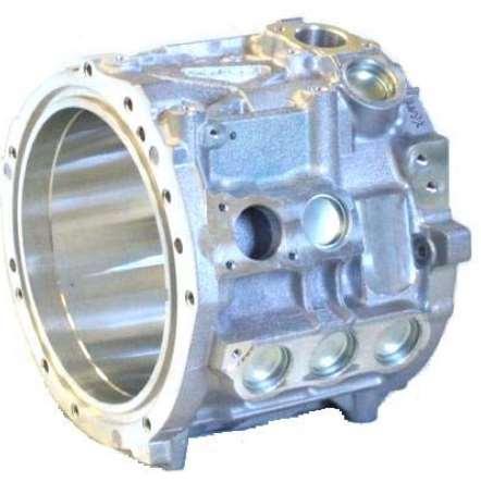
10 ORNL LEAF Motor Data Here we see the stator, winding, rotor and housing 10


11 SAE International LEAF Motor Data Here we see the water jacket, stator and rotor 11
12 LEAF Geometry Motor dimensions from teardown analysis put into motor models 48-slot, 8-pole Interior Permanent Magnet (IPM) Brushless Permanent Magnet (BPM) Design 12

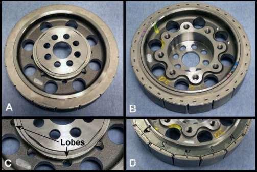
13 LEAF Geometry (Stator & Rotor) Two magnet layers: One flat magnet and one v-magnet Axial segmentation to reduce magnet eddy current losses 13

14 LEAF Geometry (Housing) 3 circumferential channels in housing act as a water jacket and forms the main cooling for the LEAF motor 14

15 LEAF Winding Design 48 slots with distributed winding High slot fill as shown below High Slot Fill Design All Phases Phase A Turns 15


16 LEAF Electromagnetic Analysis We can calculate the open circuit and on-load electromagnetic performance and compare with test data This helps identify difficult to measure design quantities like magnet grade Back-emf, cogging and torque ripple Loss density plots Flux plot (open-circuit) Flux plot (on-load) 16


17 LEAF Electromagnetic Analysis (3D) We can calculate 3D electromagnetic effects such as end leakage and magnet loss reduction due to axial segmentation Axial split PM topology to reduce eddy effects Field distribution at rated load condition 17


18 LEAF Thermal Analysis We can predict the steady-state thermal performance using a lumped circuit thermal model Predicts heat transfer and fluid flow Near instantaneous steady-state calculation as not FEA or CFD Simplified and actual thermal resistance network Temperatures at Different Nodes End Winding Active Winding Axial Variation of Temperature 18

19 LEAF Thermal Analysis (Lumped Circuit) We can quickly predict the transient thermal performance using a very fast lumped circuit thermal model Seconds to calculate the thermal transient even if a very complex duty cycle Loss v Time Speed v Time Predicted Thermal Transient for 10 Cycles of US06 Drive Cycle 19
 to")


20 LEAF Thermal Analysis (FEA) We can use thermal finite element analysis (FEA) to predict heat transfer in components like the slot and winding We can plot the steady state temperature over the radial and axial crosssection using the lumped circuit thermal calculation results which is much faster than using a 3D FEA or CFD solution Lumped Circuit Results Used to Plot Temperature Distribution Thermal FEA Analysis for the Slot 20
")

 to")


21 LEAF Thermal Analysis (CFD) We can use computation fluid dynamics (CFD) to predict fluid flow Water Jacket Fluid Flow Temperature Profile Mesh Path Lines Static Pressure Internal Air Flow 21


22 LEAF Efficiency Loss Prediction We can calculate the electromagnetic performance at a range of torque and and speed values and then plot the efficiency map We can also plot other maps such as loss maps We can pre-calculate the optimum phase advance angle for maximum torque/amp or maximum efficiency control to minimize the number of FEA calculations required The LEAF motor has a 80kW maximum power limit imposed by the drive Efficiency Map Iron Loss Map Phase Advance Map 22


23 Validation of Electromagnetic Model (LEAF) We can validate the electromagnetic calculation by comparing the calculated and measured efficiency maps Excellent match in this case Motor-CAD Predicted Efficiency Map good match Measured Measured Efficiency Map 23
 Excellent match between the calculated and measured winding hotspot")
24 Validation of Thermal Model (LEAF) We can validate the thermal model by comparing calculated and measured thermal transients In this case we show the winding thermal transient for the motor operating at 50kW, 60kW, 70kW and 80kW (all at 7000rpm) Excellent match between the calculated and measured winding hotspot 24


25 Drive Cycle Prediction (LEAF) Here we see a prediction of the efficiency map and a thermal transient calculation of 10 repetitive cycles of the US06 Drive Cycle calculated in a few minutes as based on a network solution Efficiency Map with Drive Cycle Points Plotted Total Loss Torque vs time Predicted Thermal Transient for 10 Cycles of US06 Drive Cycle Copper Loss Iron Loss Speed vs time 25
 Presentation at ANSYS Convergence Conference, Korea, Oct 2014 Tesla Patents There is much more commercial data available https://estore.ricardo.")
26 Modelling the Tesla Model S Motor A limited amount of published data is available for the Tesla Model S EV Traction Motor Prof Ki-Chan Kim (Hanbat Uni.) Presentation at ANSYS Convergence Conference, Korea, Oct 2014 Tesla Patents There is much more commercial data available Model-S-60_Benchmarking-Overview_v2-Preview.pdf 26


27 Published Data for the Tesla Model S Motor stator, rotor, winding and water-jacket details show Parameter Value Winding layers 2 Parallel branches 2 Conductors per slot 2 Number of strands 26 Wire diameter 1.1Φ Number of Turns 1 Parameter Motor Stator Rotor Outer diameter 254Φ 155.8Φ Inner diameter 157Φ 50Φ Number of slots 60slots 74slots Stack length 152.6mm 153.8mm Skew - 1.5mm (0.23pitch) Driving Characteristic Analysis of Traction Motors for Electric Vehicle by using FEM, Prof. Ki-Chan Kim, EVEP LAB, Dept. of Electrical Eng,Hanbat National University. Ansys Electronics Expo, 7 th Oct

28 Published Data for the Tesla Model S Motor The rotor cooling system details are taken from a Tesla patent We can see the rotor cooling channels below 28


29 Tesla Model S Geometry Put motor dimensions from teardown analysis into the motor model 60-slot, 4-pole, 74 rotor bars fabricated copper rotor induction motor design We can also see the rotor cooling channels 29


30 Tesla Model S (Cooling System) Circumferential channels in housing act as a water jacket Additional rotor liquid cooling is shown We can also see the potted end windings 30


31 Tesla Model S Winding Design 60 slots with distributed winding Parameter Value Winding layers 2 Parallel branches 2 Conductors per slot 2 Number of strands 26 Wire diameter 1.1Φ Number of Turns 1 Conductors in Slot Phase A Turns All Phases 31


32 Tesla Model S Electromagnetic Analysis Calculate the electromagnetic performance using the equivalent circuit This can be calibrated using FEA Induction Motor Equivalent Circuit On Load Operation 32


33 Tesla Model S Thermal Analysis We can predict the steady-state or transient thermal performance using a lumped circuit thermal model For more detail we can predict the temperature rise in the slot using thermal FEA analysis Thermal FEA Analysis for the Slot Lumped Circuit Nodal Temperatures 33

34 Tesla Model S Efficiency Map We can calculate the electromagnetic performance at a range of torque and speed values and then plot the efficiency map We could now show transient thermal duty cycle analysis if we had time Efficiency Map 34

35 Modelling the Honda 2005 ACCORD Motor Much data available on web relating to the Honda ACCORD hybrid electric motor Oak Ridge National Laboratory 35


36 Published Data for ACCORD Motor Oak Ridge National Laboratory 36


37 Published Data for the ACCORD Oak Ridge National Laboratory 37


38 Honda ACCORD Geometry Put motor dimensions from teardown analysis into the motor model 24-slot, 16-pole brushless permanent magnet (BPM) motor design Interior permanent magnet IPM with flat magnets Passive air cooling 38


39 Honda ACCORD Winding Design Segmented stator construction with bobbin wound winding Coils wound around each tooth Conductors in Slot with Coil around a Tooth Coils around each tooth 39


 Flux")
40 ACCORD Electromagnetic Analysis We can calculate the open circuit and on-load electromagnetic performance Back-emf, cogging and torque ripple Loss density plots Flux plot (open-circuit) Flux plot (on-load) 40


41 Honda ACCORD Thermal Analysis We can predict the thermal performance using a lumped circuit thermal model or thermal FEA analysis Thermal FEA Analysis for the Slot Lumped Circuit Nodal Temperatures 41


42 Honda ACCORD Efficiency Map We can calculate the efficiency map Apply a 14kW maximum power limit in this case We can validate the electromagnetic model by comparing with test data Calculated Efficiency Map good match Measured Efficiency Map 42


43 2004 Toyota PRIUS Teardown and benchmarking data available on the ORNL web site for Toyota Prius motors (2004 Prius shown here) We can use the data to set up electromagnetic and thermal models 43


44 2004 Toyota PRIUS Efficiency Map Validation Validation based on Toyota 2004 Prius test data from ORNL published at PEMD 2012 Excellent match between measured and calculated efficiency map good match Calculated Efficiency Map Measured Efficiency Map 44


45 2017 PRIUS Plug-in Dual Motor Drive System The newest PRIUS now uses a Hairpin winding Picture from IEMDC Tutorial by James Hendershot (MotorSolver) and Timothy Burress ORNL, Miami, May,


46 Chevrolet Volt (Gen 2) 50kW Ferrite and 100kW Nd-Fe-B IPM motors Hairpin windings EV range >50 miles but no fast charge 46


47 BMW i3 125kW NdFe-B- IPM Motor 18.8 kwh lithium iron battery (range extender option) Around 80 mile range New model has 115m range with larger 33kWh battery Video s online showing motor construction 47
48 BMW i3 (Manufacturing Videos) Several motor manufacturing videos on the internet:
 & Timothy Burress (ORNL) showing a teardown analysis of the BMW i3")
49 Published Data for the BMW i3 (ORNL) Recent tutorial at IEMDC (Miami, May, 2017) by James Hendershot (MotorSolver) & Timothy Burress (ORNL) showing a teardown analysis of the BMW i3 49
 by James")
 showing a teardown analysis of the BMW")
50 Published Data for the BMW i3 (ORNL) Recent tutorial at IEMDC (Miami, May, 2017) by James Hendershot (MotorSolver) & Timothy Burress (ORNL) showing a teardown analysis of the BMW i3 50
 in the UK This is on a BMW i3")
51 Published Data for the BMW i3 We will now look at the teardown/benchmarking process that has just been started by Drive Systems Design (DSD) in the UK This is on a BMW i3 51


52 DSD i3 Motor Benchmarking Study Expanding e-machine capabilities and providing correlation baseline Stripdown and inspection Modelling Characterisation Loaded tests measurement of physical dimensions resistance testing insulation testing Today o/c test for EMF waveform friction & windage loss test Model correlation Efficiency map torque vs speed torque vs current angle James will review the model correlation process at the end of the presentation


53 DSD Teardown Analysis of i3 Motor After teardown the stator and rotor dimensions are measured and converted into a CAD geometry these can be used as input for our electromagnetic calculation DXF for i3 DXF for i3 imported to Motor-CAD to carry out EMag analysis


54 BMW i3 Motor Geometry Rather than use the CAD (DXF) geometry for the EMag calculation we can use a standard template in Motor-CAD software that gives nearly the same geometry and prediction of performance Advantage of template geometry is that parameterised so can do parametric studies. 72-slot, 12-pole, double layer IPM motor We can also see the rotor cooling channels 54


55 BMW i3 Winding Design 72 slots with distributed winding Phase A Turns All Phases Conductors in Slot 55
 Open Circuit Flux Plot (Template Geometry) On Load Open Circuit Flux Plot (Template")
56 BMW i3 Electromagnetic Analysis We can calculate the open-circuit and on-load electromagnetic performance (template geometry) Open Circuit Flux Plot (Template Geometry) On Load Open Circuit Flux Plot (Template Geometry) 56
 geometry )")
57 BMW i3 Electromagnetic Analysis Electromagnetic calculation based on the CAD (DXF) geometry ) 57


58 BMW i3 Electromagnetic Analysis Due to the 6 slice step skew used on the rotor the back emf has good sinusoidal performance Motor-CAD calculates the optimum step skew angles An FEA calculation is done for each slice The calculation is made faster by using separate treads for each slice 58


59 BMW i3 Thermal Analysis We can predict the steady-state or transient thermal performance using a lumped circuit thermal model We can vary the 3D thermal resistance resolution in both axial and radial directions to capture hotspots Required if large component of ac loss in the winding or improved cooling at one end of the motor Thermal FEA Analysis for the Slot Lumped Circuit Nodal Temperatures 59
60 Summary: Many teardown and benchmarking studied are performed by OEM, Tear 1 and other companies and research institutions Some benchmarking studies are made open source Modelling a teardown motor assists in understanding why they have certain performance characteristics and helps identify difficult to measure quantities in the teardown analysis Benchmarking studies allow comparisons of different technologies and manufacturing processes Benchmarking study models can be used as starting point for new designs State of the art motor design software allows design variables to be studied very quickly enabling optimal motor design 60
61 Electromagnetic and thermal model validation procedure for PMSMs
62 Outline Overview of test procedure Electromagnetic model validation example Loss model validation example Thermal model validation example 62
63 Definitions MUT (machine under test) Steady state - <1⁰C temperature change from ambient in 20 minutes. Soaking Using the coolant temperature to get machine to a consistent temperature before undertaking a test. 63
64 Notes on measurement Multiple thermocouples in each component of the machine and each phase as well as measurement of the housing, plate, test bed and ambient. Torque transducer, high accuracy at low Nm is very useful for measurement of losses. Rotor temperature measurement is not often available however can been reasonably well estimated for measurements of open circuit EMF. 64
65 Test procedure 1. DC test DC current is applied to the windings of the machine with a static rotor, until steady state is reached. Can be done at different current levels Used for calibration of the thermal model. Ideally all phases can be connected in series to give an equal current in all the slots. Otherwise if star use two phase. If delta shorted phase. Consider where thermocouples are placed. Important to measure voltage drop at the machine terminals not the power supply. Use this with measured current to derive the loss in the machine. If the machine is coupled to a large plate on the rig this test can be done with the MUT and off the rig. This enables calibration of any influence of the rig on cooling. This effect should not be underestimated! Delta Star 65
66 Test procedure 2. Dummy rotor Either the rotor is replaced by non-magnetic rotor or magnetic rotor is spun in an empty housing. At different speeds torque is measured to calculate friction and windage loss. Windage losses are usually small and can be estimated through a simple calculation. Frictional bearing losses are very often higher than expected and can contribute to significant unexpected temperature rise in the rotor. A high resolution torque transducer is essential, often it s best to use 2 different transducers for the low torque and high torque tests. Do the measurement in both rotational directions then average, there is typically a small offset on the torque measurement. 66
67 Test procedure 3. Open circuit test (transient) The machine is spun at different speeds with no inverter connected and the terminals open circuit. The test is fast and machine only held at each speed for a few seconds while the measurement is taken. The shaft torque is measured to deduce the losses at different speeds. The voltage is also measured at the different speeds. An oscilloscope can also be used at one low speed condition to measure the shape of the EMF waveform. A high resolution torque transducer is essential, often it s best to use 2 different transducers for the low torque and high torque tests. Do the measurement in both rotational directions then average, there is typically a small offset on the torque measurement. Smoothing or filtering the torque transducer output can be helpful so that average torque is measured. 67

68 Test procedure 4. Short circuit test (transient) The machine is spun at different speeds with no inverter connected and the terminals short circuited. Again the test is fast and machine only held at each speed for a few seconds while the measurement is taken. The shaft torque is measured to deduce the losses at different speeds. The current induced in the windings is measured. Make sure the cable used to short circuit the windings is not long (ideally <30cm), otherwise it can add extra inductance to the machine terminals. A high resolution torque transducer is also useful although the peak torque can be quite high during this test. Do the measurement in both rotational directions then average, there is typically a small offset on the torque measurement. Take the measurement rapidly to try to avoid significant temperature change during the test. Machine can be soaked beforehand. Short circuit torque characteristic 68
69 Test procedure 5. Torque Vs. Current Angle Machine is operated under load. The current is kept steady and phase advance varied from 0-90 degrees in consistent steps. This can be repeated at various current levels. Torque is measured. Ideally this is automated so the test is done quickly and temperature doesn t vary between points. Machine can be soaked to a single temperature before the test. 69
70 Test procedure 6. Thermal steady state The machine is measured at various on-load points. Different operating speeds and currents. Can also be done at short circuit if machine design is suitable. If open circuit losses are high it is also very useful to run to steady state temperature at high speed on open circuit. Thermocouples should be sampled regularly and data stored (every 30s for example). As with DC test, as well as the machine, the coolant, housing, test bed, mounting bracket and ambient should be measured. 70
71 Test procedure 7. Torque/speed curve, Efficiency map measurement Many operating points are measured rapidly. Again ideal if temperature is consistent between points. This can be achieved with soaking, automation of the rig and modulation between high load, low load and high speed and low speed measurement points. Efficiency is notoriously difficult to measure. Smoothing or filtering the torque transducer output so that average torque is measured helps, otherwise peaks and troughs in the torque waveforms cause inconsistent measurements. To measure efficiency ideally the electrical input power and mechanical output power measurement should be synchronised. 71


72 Example test and validation 36 slot 10 pole machine Interior permanent magnet rotor Distributed winding 70Nm, 20kW peak 10,000rpm max. speed. 72
73 Test rig set-up Electrical quantities measured from power analyser Torque and speed measured from transducer Temperature measured from machine thermocouples All data fed into PC, PC also controls machine drives 73

74 Automation tool Fully automated rig Enables fast and accurate measurements Ensures repeatability of tests Delta 74
75 Overview of Validation Process 1. Electromagnetic parameter validation: Back emf Short circuit current Torque production against current magnitude and angle 2. Loss model validation: DC winding loss Friction + windage loss Iron losses AC winding loss + magnet loss 3. Thermal model validation DC static temperature rise On load operation at various load points and frequencies 75
76 Electromagnetic validation Open circuit EMF at low speed. Validation of FEA modelling and magnet Br. Magnet Br can be adjusted, in this case modification wasn t required. 76

77 Electromagnetic validation Steady state short circuit current is measured Used to calibrate the end winding inductance 0.04mH required here Make sure test cable is not adding to inductance here! Insufficient inductance With additional end winding inductance 77
78 Electromagnetic validation Torque per amp and torque vs. current angle If BEMF is correct and this isn t then saturation characteristics may be wrong. Adjustment of B-H curve may be necessary Why?: B-H need information required beyond 1.8T Stacking factor causes increased saturation End leakage effects occur during saturation B-H steel properties affected during manufacturing process 78
79 Electromagnetic validation Good correlation of torque across the full operating range. The MTPA operating points Id/Iq values for this measured map were calculated using the model. 79


80 Electromagnetic validation Modelled voltage map Measured voltage map 80
81 Loss model validation DC resistance DC resistance is measured at a known temperature from DC test. The end winding length in the model is then adjusted if necessary to match the resistance. Software assumes a semi-circular path from one slot to the other, this may not be the case in reality. -> 81
82 Loss model validation Dummy rotor and open circuit losses In this case rotor is spun in an empty housing without stator and the torque measured The open circuit torque is then also measured. The difference between the open circuit losses and dummy rotor losses are assumed to be iron losses The adjustment of the iron losses in the model to account for manufacturing effects is then based upon this. It may be that the modelled hysteresis and eddy current components of the iron losses need to be independently adjusted to match the scaling with frequency Hysteresis iron loss build factor = 1.0 Eddy iron loss build factor =

83 Loss model validation short circuit losses Short circuit losses are measured across the speed range The DC component, iron losses, bearing friction and windage are now accounted for with calibrated models. The remaining loss components are AC winding losses and magnet losses. Here we have assumed that the magnet losses are correct in the FEA model and used the results to deduce the AC losses In this case the AC losses are difficult to model precisely as the windings are made of multi-stranded bundles with a random distribution and no transposition. AC losses are proportional to d^4, where d is the bundle height 83

84 Loss model validation short circuit losses Usually AC losses scale with f^2 at lower speed and become more linear at higher speed when they become inductance limited. In this case they appear to be linear throughout the speed range. 84
85 Electromagnetic & Loss model validation Modelled efficiency map Measured efficiency map 85


 106.3 106.")
86 Thermal model validation DC test DC test completed with all phases in series Calibrated model parameters: Heat transfer from flange mounting plate Interface gap from stator lamination to housing Interface gap between slot liner and lamination Test DC current (A) 85 Winding loss (W) 505 Model Winding Average (⁰C) Housing (⁰C) Flange mounting plate (⁰C)
 500 Torque (Nm) 35.3 Average winding (⁰C) 147.6 152.6 Operating Point 2 Speed (rpm) 2000 Torque (Nm) 25.4 Average winding (⁰C) 109.3 111.")
87 Thermal model validation Steady state Steady state operation points run at various speeds End winding airflow calibrated & division of losses validated. Test Model Operating Point 1 Speed (rpm) 500 Torque (Nm) 35.3 Average winding (⁰C) Operating Point 2 Speed (rpm) 2000 Torque (Nm) 25.4 Average winding (⁰C) Operating Point 3 Speed (rpm) 6000 Torque (Nm) 15.7 Average winding (⁰C)
88 Validation example summary Getting very good correlation between simulation and reality is certainly achievable However in electrical machines the challenges and uncertainties are typically in the manufacturing processes e.g. electrical steel degradation, interface gaps and layout of conductors. This uncertainties are often unknowable at design stage and cannot be solved using more computationally intensive simulation. However through model validation exercises and understanding of your own manufacturing processes high confidence in your simulations be achieved. The model validation is often also very useful in highlighting where issues and areas for improvement occur in the machine. 88
89 Please Visit us in Hall 2.1, Stand A23
Motor-CAD Software for Thermal Analysis of Electrical Motors - Links to Electromagnetic and Drive Simulation Models
 Motor-CAD Software for Thermal Analysis of Electrical Motors - Links to Electromagnetic and Drive Simulation Models Dave Staton, Douglas Hawkins and Mircea Popescu Motor Design Ltd., Ellesmere, Shropshire,
Enhancing the Design of Electric Machines through the Interaction of Software Tools. Markus Anders Electric machine sector manager CD-adpaco
 Enhancing the Design of Electric Machines through the Interaction of Software Tools Markus Anders Electric machine sector manager CD-adpaco Outline Part I: SPEED and STAR-CCM+ Enhancing the thermal design
HIGH SPEED PERMANENT MAGNET SYNCHRONOUS MOTOR / GENERATOR DESIGN FOR FLYWHEEL APPLICATIONS
 HIGH SPEED PERMANENT MAGNET SYNCHRONOUS MOTOR / GENERATOR DESIGN FOR FLYWHEEL APPLICATIONS Aleksandr Nagorny, Ph.D. National Research Council Outline Introduction Selection of the Rated Point The major
Vehicle Design Summit Electric Hub Motor (V2) Eric Conner Harvey Tang Matthew Peddie
 Eric Conner Harvey Tang Matthew Peddie") Vehicle Design Summit Electric Hub Motor (V2) Eric Conner Harvey Tang Matthew Peddie Motivation The AHPV from VDS 1.0 used an expensive, NGM electric hub motor, costing roughly $8000. (picture on right)
Vehicle Design Summit Electric Hub Motor (V2) Eric Conner Harvey Tang Matthew Peddie Motivation The AHPV from VDS 1.0 used an expensive, NGM electric hub motor, costing roughly $8000. (picture on right)
CHAPTER 4 DESIGN OF INTEGRAL SLOT AND FRACTIONAL SLOT BRUSHLESS DC MOTOR
 47 CHAPTER 4 DESIGN OF INTEGRAL SLOT AND FRACTIONAL SLOT BRUSHLESS DC MOTOR 4.1 INTRODUCTION This chapter deals with the design of 24 slots 8 poles, 48 slots 16 poles and 60 slots 16 poles brushless dc
1150 hp motor design, electromagnetic and thermal analysis
 115 hp motor design, electromagnetic and thermal analysis Qasim Al Akayshee 1, and David A Staton 2 1 Mawdsley s Ltd., The Perry Centre, Davey Close, Waterwells, Gloucester GL2 4AD phone: +44 1452 888311
DIRECT CURRENT GENERATORS
 DIRECT CURRENT GENERATORS Revision 12:50 14 Nov 05 INTRODUCTION A generator is a machine that converts mechanical energy into electrical energy by using the principle of magnetic induction. This principle
DHANALAKSHMI COLLEGE OF ENGINEERING DEPARTMENT OF ELECTRICAL AND ELECTRONICS ENGINEERING EE2302 - ELECTRICAL MACHINES II UNIT-I SYNCHRONOUS GENERATOR
 1 DHANALAKSHMI COLLEGE OF ENGINEERING DEPARTMENT OF ELECTRICAL AND ELECTRONICS ENGINEERING Constructional details Types of rotors EE2302 - ELECTRICAL MACHINES II UNIT-I SYNCHRONOUS GENERATOR PART A 1.
DC GENERATOR THEORY. LIST the three conditions necessary to induce a voltage into a conductor.
 DC Generators DC generators are widely used to produce a DC voltage. The amount of voltage produced depends on a variety of factors. EO 1.5 LIST the three conditions necessary to induce a voltage into
Motors and Generators
 Motors and Generators Electro-mechanical devices: convert electrical energy to mechanical motion/work and vice versa Operate on the coupling between currentcarrying conductors and magnetic fields Governed
2. Permanent Magnet (De-) Magnetization 2.1 Methodology
 Magnetization 2.1 Methodology") Permanent Magnet (De-) Magnetization and Soft Iron Hysteresis Effects: A comparison of FE analysis techniques A.M. Michaelides, J. Simkin, P. Kirby and C.P. Riley Cobham Technical Services Vector Fields
Permanent Magnet (De-) Magnetization and Soft Iron Hysteresis Effects: A comparison of FE analysis techniques A.M. Michaelides, J. Simkin, P. Kirby and C.P. Riley Cobham Technical Services Vector Fields
Basics of Electricity
 Basics of Electricity Generator Theory PJM State & Member Training Dept. PJM 2014 8/6/2013 Objectives The student will be able to: Describe the process of electromagnetic induction Identify the major components
Traditional Design of Cage Rotor Induction Motors. Ronald G. Harley and Yao Duan Georgia Institute of Technology November, 2009
 Traditional Design of Cage Rotor Induction Motors Ronald G. Harley and Yao Duan Georgia Institute of Technology November, 2009 Rating considerations Dimensions of a machine depend on Torque at a specific
Principles of Adjustable Frequency Drives
 What is an Adjustable Frequency Drive? An adjustable frequency drive is a system for controlling the speed of an AC motor by controlling the frequency of the power supplied to the motor. A basic adjustable
Design and Analysis of Switched Reluctance Motors
 Design and Analysis of Switched Reluctance Motors İbrahim ŞENGÖR, Abdullah POLAT, and Lale T. ERGENE Electrical and Electronic Faculty, İstanbul Technical University, 34469, Istanbul, TURKEY sengoribrahim@gmail.com,
Development Of High Efficiency Brushless DC Motor With New Manufacturing Method Of Stator For Compressors
 Purdue University Purdue e-pubs International Compressor Engineering Conference School of Mechanical Engineering 2002 Development Of High Efficiency Brushless DC Motor With New Manufacturing Method Of
8 Speed control of Induction Machines
 8 Speed control of Induction Machines We have seen the speed torque characteristic of the machine. In the stable region of operation in the motoring mode, the curve is rather steep and goes from zero torque
THE EFFECT OF SLOT SKEWING AND DUMMY SLOTS ON PULSATING TORQUE MINIMIZATION IN PERMANENT MAGNET BRUSHLESS DC MOTORS
 Indian J.Sci.Res.1(2) : 404-409, 2014 ISSN : 0976-2876 (Print) ISSN:2250-0138(Online) THE EFFECT OF SLOT SKEWING AND DUMMY SLOTS ON PULSATING TORQUE MINIMIZATION IN PERMANENT MAGNET BRUSHLESS DC MOTORS
13 ELECTRIC MOTORS. 13.1 Basic Relations
 13 ELECTRIC MOTORS Modern underwater vehicles and surface vessels are making increased use of electrical actuators, for all range of tasks including weaponry, control surfaces, and main propulsion. This
BRUSHLESS DC MOTORS. BLDC 22mm. BLDC Gearmotor Size 9. nuvodisc 32BF. BLDC Gearmotor Size 5
 BRUSHLESS DC MOTORS BLDC Gearmotor Size 9 BLDC 22mm nuvodisc 32BF BLDC Gearmotor Size 5 Portescap Brushless DC motors are extremely reliable and built to deliver the best performances. Their high power
How to Optimize Performance and Minimize Size in High Speed Applications High Performance Brushless DC Motors
 thinkmotion How to Optimize Performance and Minimize Size in High Speed Applications High Performance Brushless DC Motors I. Introduction II. III. IV. Optimization of a Brushless DC motor for high speed
Electrical Drive Modeling through a Multiphysics System Simulation Approach
 Application Brief Electrical Drive Modeling through a The electric drive system is a key application in power electronics. Optimizing such complex mechatronic system requires in-depth analysis, expertise
Flux Conference 2012. High Efficiency Motor Design for Electric Vehicles
 Flux Conference 2012 High Efficiency Motor Design for Electric Vehicles L. Chen, J. Wang, P. Lombard, P. Lazari and V. Leconte University of Sheffield, Date CEDRAT : 18 October 2012 Presented by: P. Lazari
Torque motors. direct drive technology
 Torque motors direct drive technology Why Direct Drive Motors? Fast and effective Direct-drive technology in mechanical engineering is defined as the use of actuators which transfer their power directly
Brush DC Motor Basics. by Simon Pata Business Unit Manager, Brushless DC
 thinkmotion Brush DC Motor Basics by Simon Pata Business Unit Manager, Brushless DC Ironless DC Motor Basics Technical Note Brushed DC ironless motors are found in a large variety of products and applications
Principles and Working of DC and AC machines
 BITS Pilani Dubai Campus Principles and Working of DC and AC machines Dr Jagadish Nayak Constructional features BITS Pilani Dubai Campus DC Generator A generator consists of a stationary portion called
Design of a PM Brushless Motor Drive for Hybrid Electrical Vehicle Application
 Design of a PM Brushless Motor Drive for Hybrid Electrical Vehicle Application Gui-Jia Su and John W. McKeever Oak Ridge National Laboratory, Oak Ridge, TN 37831-8038 Phone: (865) 576-7917, Fax: (865)
2. A conductor of length 2m moves at 4m/s at 30 to a uniform magnetic field of 0.1T. Which one of the following gives the e.m.f. generated?
 Extra Questions - 2 1. A straight length of wire moves through a uniform magnetic field. The e.m.f. produced across the ends of the wire will be maximum if it moves: a) along the lines of magnetic flux
Performance Comparison of Dual-Rotor Radial-Flux and Axial-Flux Permanent-Magnet BLDC Machines
 Performance Comparison of Dual-Rotor Radial-Flux and Axial-Flux Permanent-Magnet BLDC Machines Ronghai Qu, Member, IEEE Electronic & Photonic Systems Technologies General Electric Company Bldg EP, Rm 110-B,
Application Information
 Moog Components Group manufactures a comprehensive line of brush-type and brushless motors, as well as brushless controllers. The purpose of this document is to provide a guide for the selection and application
Drive circuit basics + V. τ e. Industrial Circuits Application Note. Winding resistance and inductance
 ndustrial Circuits Application Note Drive circuit basics For a given size of a stepper motor, a limited space is available for the windings. n the process of optimizing a stepper motor drive system, an
Traction Motor Design Considerations
 Traction Motor Design Considerations A concept paper in response to the FOA #DE-FOA-0000472 entitled Rare Earth Alternatives in Critical Technologies for Energy (REACT) Abstract : In vehicle drives, induction
SYNCHRONOUS MACHINES
 SYNCHRONOUS MACHINES The geometry of a synchronous machine is quite similar to that of the induction machine. The stator core and windings of a three-phase synchronous machine are practically identical
*ADVANCED ELECTRIC GENERATOR & CONTROL FOR HIGH SPEED MICRO/MINI TURBINE BASED POWER SYSTEMS
 *ADVANCED ELECTRIC GENERATOR & CONTROL FOR HIGH SPEED MICRO/MINI TURBINE BASED POWER SYSTEMS Jay Vaidya, President Electrodynamics Associates, Inc. 409 Eastbridge Drive, Oviedo, FL 32765 and Earl Gregory,
AC Induction Motor Slip What It Is And How To Minimize It
 AC Induction Motor Slip What It Is And How To Minimize It Mauri Peltola, ABB Oy, Helsinki, Finland The alternating current (AC) induction motor is often referred to as the workhorse of the industry because
SECTION 4 ELECTRIC MOTORS UNIT 17: TYPES OF ELECTRIC MOTORS
 SECTION 4 ELECTRIC MOTORS UNIT 17: TYPES OF ELECTRIC MOTORS UNIT OBJECTIVES After studying this unit, the reader should be able to Describe the different types of open single-phase motors used to drive
Motor Fundamentals. DC Motor
 Motor Fundamentals Before we can examine the function of a drive, we must understand the basic operation of the motor. It is used to convert the electrical energy, supplied by the controller, to mechanical
Induction Motor Theory
 PDHonline Course E176 (3 PDH) Induction Motor Theory Instructor: Jerry R. Bednarczyk, P.E. 2012 PDH Online PDH Center 5272 Meadow Estates Drive Fairfax, VA 22030-6658 Phone & Fax: 703-988-0088 www.pdhonline.org
KINETIC ENERGY RECOVERY SYSTEM BY MEANS OF FLYWHEEL ENERGY STORAGE
 ADVANCED ENGINEERING 3(2009)1, ISSN 1846-5900 KINETIC ENERGY RECOVERY SYSTEM BY MEANS OF FLYWHEEL ENERGY STORAGE Cibulka, J. Abstract: This paper deals with the design of Kinetic Energy Recovery Systems
Calculation of Temperature in a Large Turbine Generator with Multilayer Roebel Transposition Coils
 Calculation of Temperature in a Large Turbine Generator with Multilayer Roebel Transposition Coils Kenichi Hattori *, Kazuhiko Takahashi, Kazumasa Ide, Keiji Kobashi, Hiroshi Okabe, and Takashi Watanabe
Bericht über FEMAG 3D
 Bericht über FEMAG 3D Dr.-Ing. Bogdan Funieru Würzburg, 21 October 2008 Dr.-Ing. B. Funieru 1 Contents Motivation and Concept LUA Script Extrusion Control Periodic Boundary Condition FEMAG 2D 3D Results
d di Flux (B) Current (H)
 Current (H)") Comparison of Inductance Calculation Techniques Tony Morcos Magnequench Technology Center Research Triangle Park, North Carolina 1 VCM Baseline: Geometry Axially-magnetized MQ3-F 42 NdFeB disk Br = 131kG
Comparison of Inductance Calculation Techniques Tony Morcos Magnequench Technology Center Research Triangle Park, North Carolina 1 VCM Baseline: Geometry Axially-magnetized MQ3-F 42 NdFeB disk Br = 131kG
Simple Analysis for Brushless DC Motors Case Study: Razor Scooter Wheel Motor
 Simple Analysis for Brushless DC Motors Case Study: Razor Scooter Wheel Motor At first glance, a brushless direct-current (BLDC) motor might seem more complicated than a permanent magnet brushed DC motor,
Lab 14: 3-phase alternator.
 Lab 14: 3-phase alternator. Objective: to obtain the no-load saturation curve of the alternator; to determine the voltage regulation characteristic of the alternator with resistive, capacitive, and inductive
Lab 8: DC generators: shunt, series, and compounded.
 Lab 8: DC generators: shunt, series, and compounded. Objective: to study the properties of DC generators under no-load and full-load conditions; to learn how to connect these generators; to obtain their
BSNL TTA Question Paper-Instruments and Measurement Specialization 2007
 BSNL TTA Question Paper-Instruments and Measurement Specialization 2007 (1) Instrument is a device for determining (a) the magnitude of a quantity (b) the physics of a variable (c) either of the above
INSTRUMENTATION AND CONTROL TUTORIAL 2 ELECTRIC ACTUATORS
 INSTRUMENTATION AND CONTROL TUTORIAL 2 ELECTRIC ACTUATORS This is a stand alone tutorial on electric motors and actuators. The tutorial is of interest to any student studying control systems and in particular
Chapter 14: Inductor design
 Chapter 14 Inductor Design 14.1 Filter inductor design constraints 14.2 A step-by-step design procedure 14.3 Multiple-winding magnetics design using the K g method 14.4 Examples 14.5 Summary of key points
FLUX / GOT-It Finite Element Analysis of electromagnetic devices Maccon GmbH
 FLUX / GOT-It Finite Element Analysis of electromagnetic devices Maccon GmbH Entwurfswerkzeuge für elektrische Maschinen MACCON GmbH 09/04/2013 1 Flux software Modeling electromagnetic and thermal phenomena
Thermal Modeling and Analysis of a Wind Turbine Generator
 Thermal Modeling and Analysis of a Wind Turbine Generator Authors: Dr Bogi Bech Jensen (Associate Professor) Technical University of Denmark Mathew Lee Henriksen (PhD student) Technical University of Denmark
Contactless Power Transfer : Inductive charging of EV
 Contactless Power Transfer : Inductive charging of EV 7-12-2010 P.Bauer Delft University of Technology Challenge the future EV have to be charged December 7, 2010 2 2 Chicken and egg problem December 7,
PM734F - Technical Data Sheet Winding 28
 - Technical Data Sheet Winding 28 SPECIFICATIONS & OPTIONS STANDARDS STAMFORD AC generators are designed to meet the performance requirements of IEC EN 60034-1. Other international standards, including
Generator Stator Protection, under/over voltage, under /over frequency and unbalanced loading. Ramandeep Kaur Aujla S.NO 250447392
 1 Generator Stator Protection, under/over voltage, under /over frequency and unbalanced loading By Ramandeep Kaur Aujla S.NO 250447392 ES 586b: Theory and applications of protective relays Department of
Miniature High-Torque, DC Servomotors and DC Gearmotors
 typical applications Robotics Factory automation Medical equipment Computer peripherals and office equipment Portable, battery-operated equipment Textile machinery Packaging machinery Actuators Miniature
AC generator theory. Resources and methods for learning about these subjects (list a few here, in preparation for your research):
:") AC generator theory This worksheet and all related files are licensed under the Creative Commons Attribution License, version 1.0. To view a copy of this license, visit http://creativecommons.org/licenses/by/1.0/,
AC generator theory This worksheet and all related files are licensed under the Creative Commons Attribution License, version 1.0. To view a copy of this license, visit http://creativecommons.org/licenses/by/1.0/,
PI144K - Winding 311 APPROVED DOCUMENT. Technical Data Sheet. Generator Solutions AS
 PI144K - Winding 311 Technical Data Sheet PI144K SPECIFICATIONS & OPTIONS STANDARDS TERMINALS & TERMINAL BOX Stamford industrial generators meet the requirements of BS EN 60034 and the relevant section
WIND TURBINE TECHNOLOGY
 Module 2.2-2 WIND TURBINE TECHNOLOGY Electrical System Gerhard J. Gerdes Workshop on Renewable Energies November 14-25, 2005 Nadi, Republic of the Fiji Islands Contents Module 2.2 Types of generator systems
3. Three phase winding technology
 3. Three phase winding technology VATech Hydro, Austria Prof. A. Binder 3/1 Single layer winding Per slot only one coil side is placed. Coils manufactured as: a) Coils with identical coil span: W = τ p
Permanent Magnet DC Motors
 typical applications Robotics and factory automation Pick-and-place robots Positioning tables Welding wire feeders Automatic guided vehicles Barcoding equipment Computer and office equipment Copier and
Selecting IHLP Composite Inductors for Non-Isolated Converters Utilizing Vishay s Application Sheet
 VISHAY DALE www.vishay.com Magnetics Selecting IHLP Composite Inductors for Non-Isolated Converters INTRODUCTION This application note will provide information to assist in the specification of IHLP composite
MATHEMATICAL MODELING OF BLDC MOTOR WITH CLOSED LOOP SPEED CONTROL USING PID CONTROLLER UNDER VARIOUS LOADING CONDITIONS
 VOL. 7, NO., OCTOBER ISSN 89-668 6- Asian Research Publishing Network (ARPN). All rights reserved. MATHEMATICAL MODELING OF BLDC MOTOR WITH CLOSED LOOP SPEED CONTROL USING PID CONTROLLER UNDER VARIOUS
1. The diagram below represents magnetic lines of force within a region of space.
 1. The diagram below represents magnetic lines of force within a region of space. 4. In which diagram below is the magnetic flux density at point P greatest? (1) (3) (2) (4) The magnetic field is strongest
HCM434F - Winding 311 APPROVED DOCUMENT. Technical Data Sheet
 HCM434F - Winding 311 Technical Data Sheet HCM434F SPECIFICATIONS & OPTIONS STANDARDS Marine generators may be certified to Lloyds, DnV, Bureau Veritas, ABS, Germanischer-Lloyd or RINA. Other standards
Battery Thermal Management System Design Modeling
 Battery Thermal Management System Design Modeling Gi-Heon Kim, Ph.D Ahmad Pesaran, Ph.D (ahmad_pesaran@nrel.gov) National Renewable Energy Laboratory, Golden, Colorado, U.S.A. EVS October -8, 8, 006 Yokohama,
Simulation of Electric Drives using the Machines Library and the SmartElectricDrives Library
 Simulation of Electric Drives using the Machines Library and the SmartElectricDrives Library J.V. Gragger, H. Giuliani, H. Kapeller, T. Bäuml arsenal research, Vienna 04.09.2006 1 Contents Chapter 1: The
Unit 33 Three-Phase Motors
 Unit 33 Three-Phase Motors Objectives: Discuss the operation of wound rotor motors. Discuss the operation of selsyn motors. Discuss the operation of synchronous motors. Determine the direction of rotation
PI044E - Winding 311 APPROVED DOCUMENT. Technical Data Sheet
 PI044E - Winding 311 Technical Data Sheet PI044E SPECIFICATIONS & OPTIONS STANDARDS Stamford industrial generators meet the requirements of BS EN 60034 and the relevant section of other international standards
PI734D - Technical Data Sheet
 PI734D - Technical Data Sheet PI734D SPECIFICATIONS & OPTIONS STANDARDS Newage Stamford industrial generators meet the requirements of BS EN 60034 and the relevant sections of other national and international
On the Influence of Stator Slot shape on the Energy Conservation Associated with the Submersible Induction Motors
 American Journal of Applied Sciences 8 (4): 393-399, 2011 ISSN 1546-9239 2010 Science Publications On the Influence of Stator Slot shape on the Energy Conservation Associated with the Submersible Induction
PI734B - Technical Data Sheet
 PI734B - Technical Data Sheet PI734B SPECIFICATIONS & OPTIONS STANDARDS Newage Stamford industrial generators meet the requirements of BS EN 60034 and the relevant sections of other national and international
The DC Motor/Generator Commutation Mystery. Commutation and Brushes. DC Machine Basics
 The DC Motor/Generator Commutation Mystery One small, yet vital piece of the DC electric motor puzzle is the carbon brush. Using the correct carbon brush is a key component for outstanding motor life,
Improved PFC Boost Choke using a Quasi-Planar Winding Configuration Dave Shonts Schott Corporation 1000 Parkers Lake Road Wayzata, MN 55391
 Improved PFC Boost Choke using a Quasi-Planar Winding Configuration Dave Shonts Schott Corporation 1000 Parkers Lake Road Wayzata, MN 55391 Abstract- A novel approach to boost inductor design using a quasi-planar
Motor-CAD Links to SPEED
 Motor-CAD Links to SPEED Mircea Popescu & Dave Staton Motor Design Ltd March 2012 Topics Motor Design Ltd Motor-CAD software and other design tools marketed by MDL The SPEED Thermal Models SPEED and Motor-CAD
How to Turn an AC Induction Motor Into a DC Motor (A Matter of Perspective) Steve Bowling Application Segments Engineer Microchip Technology, Inc.
 Steve Bowling Application Segments Engineer Microchip Technology, Inc.") 1 How to Turn an AC Induction Motor Into a DC Motor (A Matter of Perspective) Steve Bowling Application Segments Engineer Microchip Technology, Inc. The territory of high-performance motor control has
1 How to Turn an AC Induction Motor Into a DC Motor (A Matter of Perspective) Steve Bowling Application Segments Engineer Microchip Technology, Inc. The territory of high-performance motor control has
Equipment: Power Supply, DAI, Wound rotor induction motor (8231), Electrodynamometer (8960), timing belt.
, Electrodynamometer (8960), timing belt.") Lab 13: Wound rotor induction motor. Objective: to examine the construction of a 3-phase wound rotor induction motor; to understand exciting current, synchronous speed and slip in this motor; to determine
Lab 13: Wound rotor induction motor. Objective: to examine the construction of a 3-phase wound rotor induction motor; to understand exciting current, synchronous speed and slip in this motor; to determine
Introduction. Three-phase induction motors are the most common and frequently encountered machines in industry
 Induction Motors Introduction Three-phase induction motors are the most common and frequently encountered machines in industry - simple design, rugged, low-price, easy maintenance - wide range of power
Inductance. Motors. Generators
 Inductance Motors Generators Self-inductance Self-inductance occurs when the changing flux through a circuit arises from the circuit itself. As the current increases, the magnetic flux through a loop due
Chapter 15: Transformer design
 Chapter 15 Transformer Design Some more advanced design issues, not considered in previous chapter: : n Inclusion of core loss + + Selection of operating flux i 1 density to optimize total loss v 1 v Multiple
www.integratedsoft.com Electromagnetic Sensor Design: Key Considerations when selecting CAE Software
 www.integratedsoft.com Electromagnetic Sensor Design: Key Considerations when selecting CAE Software Content Executive Summary... 3 Characteristics of Electromagnetic Sensor Systems... 3 Basic Selection
Application Information Fully Integrated Hall Effect Motor Driver for Brushless DC Vibration Motor Applications
 Application Information Fully Integrated Hall Effect Motor Driver for Brushless DC Vibration Motor Applications By Shaun Milano Vibration motors are used in a variety of applications including mobile phone
THIS paper reports some results of a research, which aims to investigate the
 FACTA UNIVERSITATIS (NIŠ) SER.: ELEC. ENERG. vol. 22, no. 2, August 2009, 227-234 Determination of Rotor Slot Number of an Induction Motor Using an External Search Coil Ozan Keysan and H. Bülent Ertan
D.C. Motors. Products and specifications subject to change without notice.
 D.C. Motors Order/Technical Support - Tel: (8) 677-5 / FAX: (8) 677-865 / www.crouzet-usa.com / DC Motors Selection guide Gearbox Speed Torque max (Nm).5. Type of Gearbox 8 8 8. Power usable (w) Torque
Edmund Li. Where is defined as the mutual inductance between and and has the SI units of Henries (H).
.") INDUCTANCE MUTUAL INDUCTANCE If we consider two neighbouring closed loops and with bounding surfaces respectively then a current through will create a magnetic field which will link with as the flux passes
INDUCTANCE MUTUAL INDUCTANCE If we consider two neighbouring closed loops and with bounding surfaces respectively then a current through will create a magnetic field which will link with as the flux passes
Shaft grounding. Carbon brushes for shaft grounding are used in turbo-generators, in distinct AC- and DC motors and as a special application in Ships.
 "Modern AC-Motors don't need carbon brushes and are maintenance free " Until some years ago this thrilling statement could be heard from motor OEM's. Nowadays SCHUNK supplies carbon brushes and brush holders
USE OF ARNO CONVERTER AND MOTOR-GENERATOR SET TO CONVERT A SINGLE-PHASE AC SUPPLY TO A THREE-PHASE AC FOR CONTROLLING THE SPEED OF A THREE-PHASE INDUCTION MOTOR BY USING A THREE-PHASE TO THREE-PHASE CYCLOCONVERTER
 International Journal of Electrical Engineering & Technology (IJEET) Volume 7, Issue 2, March-April, 2016, pp.19-28, Article ID: IJEET_07_02_003 Available online at http:// http://www.iaeme.com/ijeet/issues.asp?jtype=ijeet&vtype=7&itype=2
DESIGN OPTIMIZATION OF A SINGLE-SIDED AXIAL FLUX PERMANENT MAGENT IN-WHEEL MOTOR WITH NON- OVERLAP CONCENTRATED WINDING
 DESIGN OPTIMIZATION OF A SINGLE-SIDED AXIAL FLUX PERMANENT MAGENT IN-WHEEL MOTOR WITH NON- OVERLAP CONCENTRATED WINDING H Kierstead, R-J Wang and M J Kamper University of Stellenbosch, Department of Electrical
THE LUCAS C40 DYNAMO & ITS ARMATURE.
 THE LUCAS C40 DYNAMO & ITS ARMATURE. H. Holden, March 2011. The Dynamo as a DC generating machine was used extensively in the pre- Alternator era, from the early 1900 s up to the late 1960 s and early
Objectives. Capacitors 262 CHAPTER 5 ENERGY
 Objectives Describe a capacitor. Explain how a capacitor stores energy. Define capacitance. Calculate the electrical energy stored in a capacitor. Describe an inductor. Explain how an inductor stores energy.
SLOT FRINGING EFFECT ON THE MAGNETIC CHARACTERISTICS OF ELECTRICAL MACHINES
 Journal of ELECTRICAL ENGINEERING, VOL. 60, NO. 1, 2009, 18 23 SLOT FRINGING EFFECT ON THE MAGNETIC CHARACTERISTICS OF ELECTRICAL MACHINES Mohammad B. B. Sharifian Mohammad R. Feyzi Meysam Farrokhifar
Understanding the Alternator
 http://www.autoshop101.com THIS AUTOMOTIVE SERIES ON ALTERNATORS HAS BEEN DEVELOPED BY KEVIN R. SULLIVAN PROFESSOR OF AUTOMOTIVE TECHNOLOGY AT SKYLINE COLLEGE SAN BRUNO, CALIFORNIA ALL RIGHTS RESERVED
Mathematical Modeling and Dynamic Simulation of a Class of Drive Systems with Permanent Magnet Synchronous Motors
 Applied and Computational Mechanics 3 (2009) 331 338 Mathematical Modeling and Dynamic Simulation of a Class of Drive Systems with Permanent Magnet Synchronous Motors M. Mikhov a, a Faculty of Automatics,
Overview. also give you an idea of ANSYS capabilities. In this chapter, we will define Finite Element Analysis and. Topics covered: B.
 2. FEA and ANSYS FEA and ANSYS Overview In this chapter, we will define Finite Element Analysis and also give you an idea of ANSYS capabilities. Topics covered: A. What is FEA? B. About ANSYS FEA and ANSYS
COMPUTER AIDED ELECTRICAL DRAWING (CAED) 10EE65
 10EE65") COMPUTER AIDED ELECTRICAL DRAWING (CAED) EE Winding Diagrams: (i) DC Winding diagrams (ii) AC Winding Diagrams Terminologies used in winding diagrams: Conductor: An individual piece of wire placed in the
COMPUTER AIDED ELECTRICAL DRAWING (CAED) EE Winding Diagrams: (i) DC Winding diagrams (ii) AC Winding Diagrams Terminologies used in winding diagrams: Conductor: An individual piece of wire placed in the
Iron Powder Cores for Switchmode Power Supply Inductors. by: Jim Cox
 HOME APPLICATION NOTES Iron Powder Cores for Switchmode Power Supply Inductors by: Jim Cox Purpose: The purpose of this application note is to cover the properties of iron powder as a magnetic core material
BMD. Permanent Magnet AC Synchronous Motors
 BMD Permanent Magnet AC Synchronous Motors Power, control and green solutions About us 3 Bonfiglioli, one name for a large international group. It was back in 1956 that Clementino Bonfiglioli established
Direct Current Motors
 Direct Current Motors DC MOTORS The DC machine can operate as a generator and as a motor. Chap 5. Electrical Machines by Wildi, 6 e Lecturer: R. Alba-Flores Alfred State College Spring 2008 When a DC machine
An Approach for Designing Thermal Management Systems for EV and HEV Battery Packs
 An Approach for Designing Thermal Management Systems for EV and HEV Battery Packs 4th Vehicle Thermal Management Systems Conference London, UK May 24-27, 1999 Ahmad A. Pesaran, Ph.D. Steven D. Burch Matthew
Technical Guide No. 100. High Performance Drives -- speed and torque regulation
 Technical Guide No. 100 High Performance Drives -- speed and torque regulation Process Regulator Speed Regulator Torque Regulator Process Technical Guide: The illustrations, charts and examples given in
UCI274C - Technical Data Sheet
 - Technical Data Sheet SPECIFICATIONS & OPTIONS STANDARDS Newage Stamford industrial generators meet the requirements of BS EN 60034 and the relevant section of other international standards such as BS000,
EV emotors without Rare Earth Materials
 EV emotors without Rare Earth Materials James Widmer james.widmer@ncl.ac.uk Centre for Advanced Research into Power Electronics, Drives and Machines for: Transport (Air, Land, Sea) New and Renewable Energy