Installation Guide Content for P250xV-240 microinverters
|
|
|
- Penelope Warner
- 8 years ago
- Views:
Transcription

1 A C M o d u l e Installation Guide Content for P250xV-240 microinverters

2 May 15, SolarBridge Technologies, Inc. All Rights Reserved. No part of this publication may be reused in any manner nor in any form or format without prior written permission from SolarBridge Technologies, Inc. SolarBridge Technologies, Inc Waterford Centre Blvd. Bldg C, Suite 110 Austin, TX Phone: Fax: Trademarks SolarBridge Technologies, SolarBridge Pantheon, and SolarBridge PV-Dock are all trademarks of SolarBridge Technologies, Inc. All other products and services mentioned herein are trademarks or registered trademarks of their respective companies. Disclaimer The information contained in this manual is based on SolarBridge Technologies, Inc. knowledge and experience, but such information and suggestions do not constitute a warranty expressed or implied. The methods of installation, use and maintenance of SolarBridge Pantheon Inverter are beyond the control of SolarBridge Technologies. SolarBridge Technologies assumes no responsibility and expressly disclaims liability for any loss, damage or expense associated with the use, installation or operation of the SolarBridge Pantheon Inverter. Any liability of SolarBridge Technologies is strictly limited to the Limited Warranty. SolarBridge Technologies reserves the right to make changes to product specifications or to this manual without notice. PN: SBT Rev. 00

3 Contents Read this First! IMPORTANT SAFETY INSTRUCTIONS - SAVE THESE INSTRUCTIONS FCC Compliance Chapter 1: Introduction 1 Components of an AC Module 1 Grounding in the AC Cables 2 Module Layout Diagram 3 Connecting Latching Cables 5 Disconnecting Latching Cables 6 Chapter 2: Module Preparation 9 Preparing the Modules 10 Preparing the Last Module in the String 11 Chapter 3: Module Installation 13 Installing the Modules 13 Appendix A: Examples 17 Junction Box - Top Right 17 Junction Box - Top Left 18 Two Strings Two rows each 19 Two Strings Single Rows 20 Landscape Two Strings 21 Appendix B: Three-line Diagram 23 Appendix C: AC Wiring Accessories 26 Appendix D: Technical Specifications 32 Output Ratings 32 Utility Interaction 34 v v vii ACPV Module Installation Guide iii

4 iv ACPV Module Installation Guide

5 Read this First! This document contains important information and instructions to safely install an array of alternating current photo-voltaic (AC) solar modules. Failure to follow these instructions can result in equipment damage or failure, or personal injury, and might void the system warranty. The following symbols are used throughout this document to alert you to important safety information that you will need during the installation: This symbol indicates that failure to follow instructions may result in serious hardware failure. Use caution when completing this task. This symbol indicates that failure to follow instructions may result in serious personal injury. Use extreme caution when completing this task. IMPORTANT SAFETY INSTRUCTIONS - SAVE THESE INSTRUCTIONS Note to Author: Per UL1741, Clause 66, the above heading must precede the list of safety instructions. This heading must be in upper case, not less than 4.8 mm (3/16 in) high or emphasized to distinguish it from the rest of the text. The nationally recognized testing lab (NRTL) performing the listing or certification on an AC module assembly that includes this microinverter and cables might require the following statements to be included in the AC module installation instructions. There shall be no substitute for the words "CAUTION", "WARNING", or "DANGER" in the text of the following instructions. Exception: The words "WARNING" or "DANGER" may be used in lieu of "CAUTION". When used, these words shall be in upper case. Perform all electrical installations in accordance with any local codes, the National Electrical Code (NEC) ANSI/NFPA 70 for US installations, or the Canadian Electrical Code Part I, CSA C22.1 for Canada. This unit or system is provided with fixed trip limits and shall not be aggregated above 30 kw on a single Point of Common Connection. See "Utility Interaction" on page 34 for voltage and frequency trip limits. This AC module is intended for operation in an environment having a maximum ambient temperature of <<Insert manufacturer's AC module NRTL ambient temperature specification>>. ACPV Module Installation Guide v

6 Work with the local electric company and authorities having jurisdiction (AHJ) before, during, and after the installation of the solar electric system. The following are examples of possible requirements the electric company might have regarding the installation: An upgrade of the existing meter A readily accessible AC system disconnect and a diagram showing its placement An inspection or approval before connecting the system to the utility grid Qualified personnel or electric company employee to connect the system to the utility grid WARNING: Shock Hazard. AC wiring from the utility to the array junction box is energized by both utility dedicated branch circuit(s) and AC modules rated as "Utility Interactive". Opening the array's dedicated branch disconnect will also cause the AC modules to stop producing power. Proper safety procedures must be followed when installing or accessing the dedicated branch circuit wiring, which includes unplugging the AC Modules from the dedicated branch circuit. The AC module interconnecting cable system includes an internal equipment grounding conductor (EGC) connected to each module through pluggable connectors with a longer ground pin. The AC module does NOT require a DC or AC grounding electrode conductor (neutral) at the inverter, and the neutral within the AC module is isolated from ground. The AC module must be connected to a dedicated branch circuit from an AC supply system with the neutral referenced to ground at the building or structure electrical service entrance. The connector on the AC interconnecting cables is rated for disconnect under load and can be used as an NEC disconnect device. Some AHJs might require a separate disconnect next to the AC module system as well as a readily accessible disconnect. The AC cables and connectors are listed for outdoor use, are rated for 20A, and have insulation rated to a minimum temperature of 90C. These cables are listed for use with AC modules. The AC dedicated branch circuit wiring from the readily accessible disconnect to the AC module array must include an equipment grounding conductor (EGC) run in the same raceway or cable as the AC circuit conductors. This EGC must be connected to the green colored conductor of the transition cable, which is part of the AC module interconnecting cable system. The AC module interconnecting cable system provides an internal EGC for grounding the AC modules only. Other metal structures, such as mounting systems, must be grounded per code. If a module is removed from within the string, it is recommended that you bridge the gap in the string using an AC extension cable. Inserting an extension cable maintains ground continuity to subsequent modules in the string. See "AC Wiring Accessories" on page 26 for a list of available extension cables. Other auxiliary grounding methods may be used. The metal components of the AC module, including frame and microinverter, can reach temperatures of approximately 80C or more under extreme environmental conditions. To reduce risk of burns, use appropriate safety procedures when handling. CAUTION: To reduce the risk of fire, connect only to a circuit that has a dedicated 20 amperes maximum overcurrent protection in accordance with the National Electrical Code, ANSI/NFPA 70. vi ACPV Module Installation Guide
 and AC modules rated as \"Utility Interactive\".")
7 For a 240 V split phase system, no more than 16 AC modules can be connected to a single dedicated branch circuit. The AC module output is Utility Interactive. To provide proper ventilation to the underside of the module, install modules with a minimum space of 1 inch between the module and the mounting surface. NOTE: The 1 inch is the minimum for the inverter CSA certification. However, additional distance might be required to maintain a module backsheet temperature less than 85C. The AC Module is provided with an integral microinverter and is NRTL listed as an assembly for outdoor PV applications. There is no direct current (DC) field wiring required and the integral microinverter has no serviceable parts inside. The following caution is provided as part of the microinverter certification: CAUTION - Risk of Electric Shock! Do not remove cover. No user serviceable parts inside. Refer servicing to qualified service personnel. Both AC and DC voltage sources are terminated inside this equipment. Each circuit must be individually disconnected before servicing the microinverter. When the photovoltaic module is exposed to light, it supplies a DC voltage to the microinverter. FCC Compliance This equipment has been tested and found to comply with the limits for a Class B digital device, pursuant to Part 15 of the FCC Rules. These limits are designed to provide reasonable protection against harmful interference in a residential installation. This equipment generates, uses and can radiate radio frequency energy and, if not installed and used in accordance with the instructions, may cause harmful interference to radio communications. However, there is no guarantee that interference will not occur in a particular installation. If this equipment does cause harmful interference to radio or television reception, which can be determined by turning the equipment off and on, the user is encouraged to try to correct the interference by one or more of the following measures: Reorient or relocate the receiving antenna. Increase the separation between the equipment and receiver. Connect the equipment into an outlet on a circuit different from that to which the receiver is connected. Consult the dealer or an experienced radio/tv technician for help. Changes or modifications not expressly approved by the party responsible for compliance could void the user s authority to operate the equipment. ACPV Module Installation Guide vii

8 viii ACPV Module Installation Guide

9 1 Chapter Introduction 1: The solar module you are about to install is equipped with a solar microinverter that converts the direct current (DC) power generated by a photovoltaic (PV) module into the alternating current (AC) power used in homes and businesses. Integrating this microinverter with the standard PV module results in an AC module that is the safest module on the market. You no longer need to connect the DC power to a separate microinverter or to a large, centralized inverter, eliminating exposure to potentially lethal DC voltages. Modules arrive at the installation site with the integrated microinverter and its fully-insulated AC connection cable already installed. The DC voltage produced by the module is fed directly into the microinverter. Wiring the modules together is a simple matter of plugging the attached AC cable into the insulated cable of the neighboring module. The reduced risk has the added benefit of reducing the overall installation time. NOTE: For the purposes of this document, a string is defined as the set of AC modules connected in parallel to a dedicated 20A branch circuit. An array refers to the entire installation of one or more strings connected to the structure s AC service equipment. Components of an AC Module SolarBridge DC-to-AC microinverter Module's Junction Box Insulated AC Cable, which contains an equipment grounding conductor (EGC) Mid-Cable Junction AC Cable Connector See "AC Wiring Accessories" on page 26 for a list of installation accessories such as cables and wire clips. NOTE: The AC cable connectors have been rated for disconnect under load. ACPV Module Installation Guide 1

10 Grounding in the AC Cables NOTE: Perform all electrical installations in accordance with any local codes, the National Electrical Code (NEC) ANSI/NFPA 70 for US installations, or the Canadian Electrical Code Part I, CSA C22.1 for Canada. The AC cable attached to the microinverter and all accessory cables are fully insulated and contain an equipment grounding conductor (EGC). The full ground path from the transition cable to the module frame follows: The transition cable's green conductor is connected to the EGC from the utility dedicated branch circuit. All connectors have green ground contacts that are longer than the circuit contacts. This extra length ensures the ground is the first to make contact when connecting modules and the last to break contact when disconnecting modules. The AC ground wire inside the microinverter makes a bolted termination to the microinverter chassis and is environmentally sealed. The microinverter chassis is bonded at the factory to the module frame with stainless steel hardware to provide ground continuity to the AC PV module frame. The AC cable grounding path has been tested by a NRTL. Before an AC module assembly can be labeled with the NRTL certification mark and shipped from an authorized and inspected factory, each assembly must pass a ground continuity check to verify electrical continuity from the AC cable ground contact to the module frame. The AC cable provides equipment grounding for the AC module only. It is the installer's responsibility to ensure that any metallic parts in contact with the module (i.e. mounting systems) are provided with a means of equipment grounding according to the manufacturer s instructions and local code. Because the DC power is internal to the module, a grounding electrode conductor (GEC) is not required. Because the AC modules are connected in a daisy chain fashion, disconnecting one module from within the string removes power and ground from subsequent modules in the string. Extreme care should be taken to ensure that no other energized sources are adjacent to these ungrounded modules, or auxiliary grounding methods must be provided. If a module is removed from within the string, it is recommended that you bridge the gap in the string using an AC extension cable. Inserting an extension cable maintains ground continuity to subsequent modules in the string. See "AC Wiring Accessories" on page 26 for a list of available extension cables. Other auxiliary grounding methods may be used. A best practice for all solar module installers, especially those in areas with frequent lightning, is to secure the module support rails and hardware using grounding hardware that has been certified to meet 2 ACPV Module Installation Guide

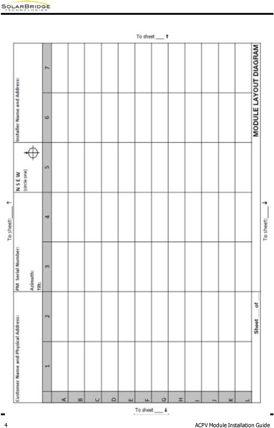
11 requirements for grounding systems. Connect the entire structure to a grounding electrode system using a dedicated, suitably sized, copper conductor. NOTE: The conductor used for lightning protection from the structure to the grounding electrode system must not be run inside the same conduit that contains the EGC and AC circuit conductors. Module Layout Diagram A module layout diagram is a paper model describing the configuration of the array and the placement of each module in the array. Following the installation, this information is recreated within the monitoring tool enabling the module owner, service providers, and system administrators to monitor the performance of each module. TIP: It is recommended that you always create the module layout diagram and add the information to your monitoring tool regardless of whether the module owner requests monitoring. The layout diagram uses the serial number of the microinverter to identify where each module is installed in the array. Use the module layout template below to create a module layout diagram of your installation site. 1. Fill in the data requested at the top of the table. 2. Before a module is installed, peel the serial number sticker from the mid-cable junction. 3. Place the sticker in the same location in the table relative to the microinverter's position in the actual array. TIP: As you place stickers in the table, don't get too far ahead of the actual installation. Modules could end up installed out of order with the placement of the stickers. 4. Fill in the sheet number information at the bottom of the table. 5. When complete, use the layout diagram to recreate the array in the monitoring tool. ACPV Module Installation Guide 3

12 4 ACPV Module Installation Guide
13 Connecting Latching Cables 1. Align and insert the female connector into the latch male connector. Each connector has alignment groves and ridges that ensure the connectors cannot be plugged together incorrectly. Ensure both ends are fully seated before attempting to close the latch. Latch male connector Female connector Alignment grooves 2. Snap the latch in place to secure the connectors. Ensure both sides of the latch are engaged. ACPV Module Installation Guide 5

14 Disconnecting Latching Cables Use the provided disconnect tool to safely release the latching connectors. 1. Insert the ends of the tool into the latch recesses as shown in the images below. You will feel and hear a click when the tool is fully seated. 6 ACPV Module Installation Guide

15 2. Use your thumbs, firmly push or pull the top of the disconnect tool toward the latch male connector until the latch snaps free. ACPV Module Installation Guide 7

16 8 ACPV Module Installation Guide

17 2 Chapter Module 2: Preparation The preparation steps described in this section apply to a large majority of the modules you will install. Occasionally, however, situations will dictate that the cables be routed differently. Or, your individual experiences will determine steps or cable management techniques that work better for you or, more importantly, for your inspectors. Before you begin preparing the modules for installation, consider the following items, which might require changes to the cable management of one or more modules: Where is the junction or transition box located in relation to the module that will connect to it? Whether the box is located to the left or right of the array (as viewed from the ground facing the installed array) determines which transition cable you need (male or female) and what preparation is needed for the final module in the string. With the junction or transition box to the left, a female transition cable is required. The final module in the string will require an end cap be plugged into the mid-cable junction. With the junction or transition box to the right of the array, a male transition cable is needed. The final module will require additional cable management to secure the end of the AC cable. Before connecting the transition cable, calculate the distance from the transition box to the module plus the distance under the module to reach the appropriate AC connector. This will determine the length of transition cable that you will need. How will you manage the transition cable? If the transition box is under the module, you might be able to use the module's cable clips to secure the transition cable to the module frame. TIP: Always place cable clips at least three inches from a plug or mid-cable junction to ensure proper stress relief. Do you need any extension cables? Will the extension cable reach from connector to connector or is it necessary to modify the standard cable management of one or both modules to make the connection easier? How will you manage the extension cables? If the extension cables will connect two rows of modules in the same string, use cable clips to secure the transition cable to the module frame. Including waves or loops in the cable between clips can help manage slack. If the extension cable is running across open roof, another cable management system will be needed to keep the extension cable off of the roof and protected from the sun. If the distance to be crossed is longer than the length of the extension cable, you must transition back to standard building wiring systems to span the distance. Use a transition cable to connect the module into a junction or transition box and wire according to local and NEC or CEC standards. ACPV Module Installation Guide 9

18 The preparation and installation instructions included in this section are general instructions for installing AC modules on most mounting systems. In some cases, it might be necessary to modify these instructions to accommodate specific installation requirements. For example, if you encounter more cable slack than is represented in these diagrams, use standard cable management practices to secure the excess cable off of the roof. NOTE: The graphics in this chapter view the back or underside of the module as you would see it when performing the procedure. Preparing the Modules AC modules require minimal preparation before installation. Simply secure the connector cable in the already attached cable clip and attach the 90-degree clip to the side of the module frame. You're ready to install. Secure the cable in the S clip. Attach the 90-degree clip to the side frame. During shipping, the AC cable connectors are securely fastened to prevent movement. Use caution when unpacking the module to ensure the connectors do not swing loose and cause damage to the module backsheet or underlying solar cell. 10 ACPV Module Installation Guide

19 Preparing the Last Module in the String The last module in the string will require a slightly different preparation. The last module will have an unused AC connector. One end or the other will not be plugged into a neighboring module. This unused connector must be secured under the modules and off of the rooftop. Use an appropriate cable clip and end cap as shown in the following example: ACPV Module Installation Guide 11

20 12 ACPV Module Installation Guide

21 3 Chapter Module 3: Installation This section describes how to lay down and interconnect SolarBridge-enabled AC modules on a previously installed mounting system. No attempt is made to describe how to install the mounting system on the roof or how to use module clamps. Before installing the mounting system, ensure that mounting rails will be positioned below the microinverter once the module is installed. The microinverter extends beyond the edge of the frame of most modules. Do not install modules with the microinverter resting on the mounting rail. The frame of the installed module must rest firmly on the mounting rail. Installing a module with the microinverter resting on the rail and uneven contact between the frame and the rail can cause damage to the microinverter and the module. NOTE: Perform all electrical installations in accordance with any local codes, the National Electrical Code (NEC) ANSI/NFPA 70 for US installations, or the Canadian Electrical Code Part I, CSA C22.1 for Canada. NOTE: Follow all module manufacturer's safety handling instructions while moving or installing modules. The metal components of the AC module, including frame and microinverter, can reach temperatures of approximately 80C. To reduce risk of burns, use appropriate safety procedures when handling. Installing the Modules The ideal installation path is to begin closest to the installed transition box and plug in each module as you move away from the box. Depending on the configuration of your array and the location of the transition box, this path may not be feasible. For example, in a 2-row configuration, we recommend installing the bottom row first and working up toward the transition box, which is likely mounted higher up the roof. The following diagram shows two installed modules as viewed from the bottom or underside of the module. ACPV Module Installation Guide 13
22 1. Connect the transition cable to the junction or transition box according to NEC/CEC and local standards. 2. Install the first module, nearest to the transition box, according to racking system instructions. 3. Plug the transition cable into the connector of the first module and close the connector latch. Before connecting modules to transition cable, ensure the neutral and ground wires are properly landed and the AC string overcurrent protection device is in the OFF position. 14 ACPV Module Installation Guide
23 4. Install the second module. 5. Reach under the top edge of the first module and plug in the AC cable from new module. Close the latch. TIP: For end- or edge-mount racking systems, it might be necessary to lift the top of the module slightly above the frame to reach the plug. 6. Repeat steps 4 and 5 until you reach the end of the row. See "Module Preparation" on page 9 for information on preparing the final module in the string. If the string will continue to another row, then an extension cable is needed. Plug the extension cable into the current module and place it in the general vicinity of where the next module will be installed. Use appropriate cable management strategies to secure the extension cable. TIP: For rail mount systems, lay the extension cable over the rails on which the next module will be installed. This ensures that the cable remains under the module for protection from the sun and uses the rails to keep the cable off the roof surface. Once the module is installed, you can also secure the cable to the module frame with cable clips, if necessary. ACPV Module Installation Guide 15
24 16 ACPV Module Installation Guide
25 A Appendix Examples A: The diagrams in this appendix provide examples of array configurations you might encounter and the types of cables necessary for each configuration. The graphics in this appendix view the front of the module as you would see it when installed. Junction Box - Top Right ACPV Module Installation Guide 17
26 Junction Box - Top Left 18 ACPV Module Installation Guide
27 Two Strings Two rows each ACPV Module Installation Guide 19
28 Two Strings Single Rows 20 ACPV Module Installation Guide
29 Landscape Two Strings ACPV Module Installation Guide 21
30 22 ACPV Module Installation Guide
31 B Appendix Three-line B: Diagram The table below contains information and installer notes relevant to the 3-line drawing on the next page. Locate the numbered callouts in the diagram. Typical Wire Type: THWN or THWN-2 Power Manager is connected directly to the service panel. Optionally, the Power Manager can be connected to a NEMA 5-15 single receptacle outlet wired directly to the service panel. Inverter output circuit: Direct to service entrance panel (as shown) or to a sub-panel off a higher rated breaker in the service entrance panel. Supplied by installation company as part of Balance of System (BOS) components. Typical Wire Type: Depends on wiring method to array. Size for 20 amp dedicated branch: minimum 12Awg but may be larger due to temperature derating in conduit or voltage drop due to distance. Transient voltage surge suppressor recommended for sites subject to lightning. NOTE: See NEC or CEC for AC wiring guidance, breaker placement, and panel loading. Exterior-rated electrical work box with distribution block or terminal strip rated for 240 VAC 20A (supplied by installation contractor). NOTE: Check with the AHJ for requirements for a separate AC disconnect to be installed next to the PV array ACPV Module Installation Guide 23
32 Grounding lugs and external ground wires: The AC cable provides equipment grounding for the AC module only. It is the installer's responsibility to ensure that any metallic parts in contact with the module (i.e. mounting systems) are provided with a means of equipment grounding according to the manufacturer s instructions and local code. In areas subject to lightning, it is recommended to provide auxiliary grounding between the AC module frame and the racking to bond all metal together. This can be done with straps or fasteners approved for grounding PV module frames. The entire array structure should then be connected directly to the ground electrode using a suitably sized copper conductor. NOTE: Do not run this conductor in the conduit with the EGC or AC power conductors. Failure to provide proper grounding can void equipment warranty in the case of lightning strike. Typical Wire Type: Green insulated wire size must be no smaller than largest conductor in the PV system. If the ground wire is external, use a minimum 6 AWG per NEC or CEC. AC Module Interconnecting Cables: Exterior-rated AC cable with equipment grounding conductor (EGC) integrated into the AC module. Cables are rated for disconnect under load and can be used as an NEC disconnect device. Plug and Play locking connectors require cable release tool to disconnect. 24 ACPV Module Installation Guide
33 ACPV Module Installation Guide 25
34 C Appendix AC Wiring C: Accessories The following AC wiring accessories are available to assist in any array configuration you will encounter. Part Name Model Number Description Standard Cable Clip SBT-AC-CCS Attaches to the edge of the module frame and holds the AC cable parallel to the frame edge. Available in boxes of Degree Cable Clip 90-Degree Cable Clip Latch Male End Cap SBT-AC-CCA Attaches to the edge of the module frame and holds the AC cable perpendicular to the frame edge. Available in boxes of 500. SBT-AC-CCA-01 Attaches to the edge of the module frame and holds the AC cable perpendicular to the frame edge. Ships attached to microinverter cable Replacement parts available in boxes of 500. SBT-AC-ECM Covers the female cable connector at the end of a string to protect the AC interconnecting cable from dirt and moisture. Available in boxes of 250. Female End Cap SBT-AC-ECF Covers the latch male cable connector at the end of a string to protect the AC interconnecting cable from dirt and moisture. Available in boxes of 250. ACPV Module Installation Guide 26
35 Part Name Model Number Description Transition Cable SBT-TCF-5 SBT-TCF-10 Female cable connector on one end and 100 mm of stripped wires on the other. 20A, exterior-rated 4-wire (L1, L2, N, and Ground) cable. Available in 5' and 10' lengths. Each cable is shipped with one cable release tool. 27 ACPV Module Installation Guide
36 Part Name Model Number Description SBT-TCM-5 SBT-TCM-10 Latch male cable connector on one end and 100 mm of stripped wires on the other. 20A, exterior-rated 4-wire (L1, L2, N, and Ground) cable. Available in 5' and 10' lengths. Each cable is shipped with one cable release tool. ACPV Module Installation Guide 28
37 Part Name Model Number Description Extension Cable SBT-ECMF-5 SBT-ECMF-10 Female cable connector on one end and latch male cable connector on the other. 20A, exterior-rated 4-wire (L1, L2, N, and Ground) cable. Available in 5' and 10' lengths. SBT-ECMM-5 SBT-ECMM-10 Latch male interconnecting cable connectors on both ends. 20A, exterior-rated 4-wire (L1, L2, N, and Ground) cable. Available in 5' and 10' lengths. 29 ACPV Module Installation Guide
38 Part Name Model Number Description SBT-ECFF-5 SBT-ECFF-10 Female cable connectors on both ends. 20A, exterior-rated 4-wire (L1, L2, N, and Ground) cable. Available in 5' and 10' lengths. Cable Conversion Kit SBT ACK-01 Use this kit with high-efficiency solar modules. 9" conversion cable with female cable receptacle on one end and latch male cable connector on the other end. 11" conversion cable with female cable connector on one end and male cable plug on the other end. One disconnect tool for each cable type. ACPV Module Installation Guide 30
39 Part Name Model Number Description Cable Conversion Kit SBT ACK-02 Use this kit with standard solar modules. 9" conversion cable with female cable receptacle on one end and latch male cable connector on the other end. 21" conversion cable with female cable connector on one end and male cable plug on the other end. One disconnect tool for each cable type. 31 ACPV Module Installation Guide
40 D Appendix Technical D: Specifications Note to Author: The specification included in this section are related to the SolarBridge Pantheon Inverter only. You must add the module specifications. Output Ratings Parameter Rating Output power factor rating 0.99 Operating voltage range (ac) (L-L) 1 Operating frequency range or single frequency 1 Number of phases 1 2 Nominal output voltage (ac) Normal output frequency V Hz 240 V 60 Hz Maximum continuous output current (ac) A 3 Maximum continuous output power (ac) Utility interconnection voltage and frequency trip limits and trip times 238 W See "Utility Interaction" on page 34 Total Demand Distortion (TDD) /Individual harmonics (per IEEE 1547) < 5% (Passed up to 40 th harmonic) Maximum units per 20 amp dedicated branch circuit See "Utility Interaction" on page 34 2 Single-phase device requiring two of the phases (L1 and L2) for power production and a neutral for voltage sensing only, per IEEE Maximum overload current at peak module performance combined with low grid voltage is 1.25A. 4 This is the maximum number of microinverters that can be connected in parallel to a single dedicated branch circuit, which is protected by a circuit breaker rated at 20 A. This number is derived based on the requirements of the National Electrical Code (NEC) and the current rating of the microinverter. If more than this number of microinverters needs to be installed, additional 20-A branches must be used, keeping the number of microinverters on each branch less or equal to this number. ACPV Module Installation Guide 32
41 Maximum output fault current (ac) and duration 11.9 Apk, 0.31 Arms, total duration 1.2 ms Maximum output overcurrent protection 20 A 4 33 ACPV Module Installation Guide

42 Utility Interaction a - Non-adjustable maximum clearing times b - Nominal voltage equals 120V phase to neutral c - Trip limit accuracy: Voltage - ±2.5% based on 120V nominal, frequency- ±0.1 Hz ACPV Module Installation Guide 34
43 35 ACPV Module Installation Guide
AC Module Installation Guide Content
 AC Module Installation Guide Content for ET-P660250AC May 9, 2012 2011-2012 ET Solar Group All Rights Reserved. No part of this publication may be reused in any manner nor in any form or format without
AC Module Installation Guide Content
 AC Module Installation Guide Content for ET-P660250AC May 9, 2012 2011-2012 ET Solar Group All Rights Reserved. No part of this publication may be reused in any manner nor in any form or format without
Application Bulletin 103 - NEC Reference Guide for SolarBridge-Enabled AC Module Installers
 9229 Waterford Centre Dr. Bldg C, Suite 110 Austin, Tx 78758 Application Bulletin 103 - NEC Reference Guide for SolarBridge-Enabled AC Module Installers Current Version: 13 AC Modules are a new product
Model Number Electrical Compatibility Module Connector Type. M250-60-2LL-S22 60 cell PV module MC-4 Type 2 Locking
 TECHNICAL BRIEF M250 Microinverter System Installation Planning The M250 Microinverter The Enphase M250 Microinverter is a powerful and efficient grid-tied microinverter. It is compatible with most 60-cell
Wiser Panel Meter, Model Number WISERCTPM200 Installer s Guide
 Instruction Bulletin EAV85226 08/2014 Wiser Panel Meter, Model Number WISERCTPM200 Installer s Guide Retain for future use. Product Description Kit Contents The Wiser Panel Meter is for use in energy management
SOLAR PV STANDARD ELECTRICAL PLAN Microinverter Systems for Single Family Dwellings
 *** Provide this document to the inspector along with ALL system installation instructions *** Project Address: Scope: Standard plan for the installation of grounded microinverter solar PV systems, not
What are the basic electrical safety issues and remedies in solar photovoltaic installations?
 What are the basic electrical safety issues and remedies in solar photovoltaic installations? Presented by: Behzad Eghtesady City of Los Angeles Department of Building and Safety Topics Covered Photovoltaic
Safety and Installation Instructions for AC Modules
 Safety and Installation Instructions for AC Modules United States and Canada Contents of this manual are subject to change without notice. For the latest guide please refer to www.sunpower.com/pvinstallguideacmodule
INSTALLATION GUIDELINES for SOLAR PHOTOVOLTAIC SYSTEMS 1
 City of Cotati Building Division 201 W. Sierra Ave. Cotati, CA 94931 707 665-3637 Fax 792-4604 INSTALLATION GUIDELINES for SOLAR PHOTOVOLTAIC SYSTEMS 1 Any PV system on a new structures should be included
CITY OF LOS ANGELES CALIFORNIA
 BOARD OF BUILDING AND SAFETY COMMISSIONERS VAN AMBATIELOS PRESIDENT E. FELICIA BRANNON VICE-PRESIDENT JOSELYN GEAGA-ROSENTHAL GEORGE HOVAGUIMIAN JAVIER NUNEZ CITY OF LOS ANGELES CALIFORNIA ERIC GARCETTI
How To Plan Out An Array Of Solar Panels
 CITY OF DOWNEY COMMUNITY DEVELOPMENT, BUILDING AND SAFETY 11111 Brookshire Avenue Downey, CA 90241 562.904.7142 (www.downeyca.org) B SECTION 01/01/2011 EFFECTIVE DATE PHOTOVOLTAIC 032 FORM NUMBER 2013
Solar Panel Installations
 Solar Panel Installations Page 1 of 6 SINGLE-FAMILY RESIDENTIAL CHECKLIST City of Hayward Development Services Department Revised: 7-09-15 PERMIT REQUIREMENTS Permits are required for all solar panel installations.
AC Unison Installation Guide
 BenQ Solar AC Unison Solar Power Systems Installation guide AC Unison Installation Guide BenQ Solar AC Unison Solar Power Systems Installation guide Table of Contents 1. AC Unison Solar Power System Overview...2
2011/2008/2005 NATIONAL ELECTRICAL CODE SOLAR PV CODE COMPLIANCE REFERENCE
 2011/2008/2005 NATIONAL ELECTRICAL CODE SOLAR PV CODE COMPLIANCE REFERENCE PAGE 1 OF 5 This Reference provides a very comprehensive list of aspects of a solar PV installation that could be reviewed, clarifying
GSM-EXT Cable Assembly Installation Guide
 GSM-EXT Cable Assembly Installation Guide For Documentation and Online Support: http://www.security.honeywell.com/hsc/resources/mywebtech General Information The GSM-EXT cable assembly is used to connect
Engage Coupler. Engage Coupler Chase
 TECHNICAL BRIEF Wire Management in an Enphase System The Enphase Microinverter System installs much more quickly than other PV (photovoltaic) system technologies. This is partly due to the plug-and-play
Enphase Microinverters and Ungrounded Renewable Energy Systems: Canadian Electrical Code Compliance
 WHITE PAPER Enphase Microinverters and Ungrounded Renewable Energy Systems: Canadian Electrical Code Compliance Overview Enphase has developed a new microinverter family that includes the M250 and new
AMFA-27 AMFA-29. Operator s Manual & Installation Instructions. Rev. 2.5
 AMFA-27 AMFA-29 Operator s Manual & Installation Instructions Rev. 2.5 Date: 17 July, 2010 Permanently-connected, utility Interactive, single-phase, inverters Model AMFA-27 WIND TURBINE INVERTER (240 VAC
2013 VTech Printed in China 91-009656-000 US
 Rechargeable Power Pack User s Manual 2013 VTech Printed in China 91-009656-000 US INTRODUCTION The Rechargeable Power Pack makes it easier than ever to keep the InnoTab 3 or InnoTab 3S charged and ready
White Paper SolarEdge Three Phase Inverter System Design and the National Electrical Code. June 2015 Revision 1.5
 White Paper SolarEdge Three Phase Inverter System Design and the National Electrical Code June 2015 Revision 1.5 Shalhevet Bar-Asher; SolarEdge Technologies, Inc. Bill Brooks, PE; Brooks Engineering LLC
User Manual. Replus-250 Replus-250A Replus-250B. U.S.A Add: 301 Howard St, Suite 850, San Francisco, CA 94105. T: +1 415 852 7418
 User Manual Replus-250 Replus-250A Replus-250B U.S.A Add: 301 Howard St, Suite 850, San Francisco, CA 94105. T: +1 415 852 7418 Australia Add: 18 Corporate Blvd. Bayswater, VIC 3153, Australia T: +61 481
MCR1900 Media Converter 19-Slot Chassis
 MCR1900 Media Converter 19-Slot Chassis Installation Guide Part #5500304-11 Copyright Statement This document must not be reproduced in any way whatsoever, either printed or electronically, without the
City of San Diego Residential Photovoltaic Systems Inspection Guidelines
 City of San Diego Residential Photovoltaic Systems Inspection Guidelines The purpose of inspections by DSD staff is to ensure compliance with the California Electrical Code (CEC), other applicable codes
SNQ-60x0-320 Series Data Center Switch. Quick Installation Guide
 Introduction This guide is to assist the reader with the most basic form of installation and connection to switches in this series. As there is more than one switch in this series, the diagrams might slightly
User Manual. RK-2d / RK-2t. dedicated KVM switch and rackmount screen technology. Designed and manufactured by Austin Hughes
 dedicated KVM switch and rackmount screen technology User Manual RK-2d / RK-2t 1U Short Depth Keyboard Drawer Designed and manufactured by Austin Hughes 751 Legal Information First English printing, October
DVI DA2 and DVI DA 4 User Guide
 DVI DA2 and DVI DA 4 User Guide This guide describes the installation and operation of the Extron DVI DA2 and DVI DA4 Distribution Amplifiers. Unless stated otherwise, distribution amplifier or the unit
HP UPS R1500 Generation 3
 HP UPS R1500 Generation 3 Installation Instructions Part Number 650952-001 NOTE: The rating label on the device provides the class (A or B) of the equipment. Class B devices have a Federal Communications
Mercury Helios 2 ASSEMBLY MANUAL & USER GUIDE
 Mercury Helios 2 ASSEMBLY MANUAL & USER GUIDE TABLE OF CONTENTS INTRODUCTION...1 1.1 MINIMUM SYSTEM REQUIREMENTS 1.1.1 Apple Mac Requirements 1.1.2 PC Requirements 1.1.3 Supported PCIe Cards 1.2 PACKAGE
Expedited Permit Process for PV Systems AC Module
 Module The Solar America Board for Codes and Standards (Solar ABCs) Expedited Permit Process provides a means to differentiate systems that can be permitted quickly and easily due to their similarity with
County of Riverside Building and Safety Department
 County of Riverside Building and Safety Department Mike Lara Director Photovoltaic Permitting Guidelines The information provided in this document is general and is intended only as a guide. Each project
Enphase M250 Microinverter
 INSTALLATION AND OPERATION MANUAL Enphase M250 Microinverter with integrated ground no GEC required 141-00022, Rev 01 Contact Information Enphase Energy Inc. 1420 N. McDowell Blvd. Petaluma, CA 94954 http://www.enphase.com
This equipment has been tested and found to comply with the limits for a Class B digital device, pursuant to part 15 of the FCC Rules.
 Power Max Level 2 Charging Station en Installation and Operating Instructions This equipment has been tested and found to comply with the limits for a Class B digital device, pursuant to part 15 of the
PT-6000 Power Tower INSTALLATION MANUAL SPECIFICATIONS
 PT-6000 Power Tower INSTALLATION MANUAL 10.5 9.75 12 22.75 10.75 MAXIMUM SOIL HEIGHT: DO NOT ALLOW FILL TO EXCEED THIS LEVEL! 11.5 4 4 13 Optional PT-BASE for new installations or when previous 2000/6000
Square D Clipsal DIN-Rail Four-Channel Auxiliary Input Unit
 Square D Clipsal DIN-Rail Four-Channel Auxiliary Input Unit SLCLE5504AUX for Use with Wired C-Bus Networks Instruction Bulletin Retain for future use. Square D Clipsal DIN-Rail Four-Channel Auxiliary Input
ATS Overhead Table Shelf System INSTRUCTION MANUAL
 ATS Overhead Table Shelf System INSTRUCTION MANUAL ATS Overhead Table Shelf System Instruction Manual Warranty Newport Corporation warrants this product to be free of defects in material and workmanship
Request for Proposals for Photovoltaic System Installation
 Request for Proposals for Photovoltaic System Installation Presented by: Prepared by: Location: Contact: Date: Capitol Hill Housing Foundation Bonneville Environmental Foundation, Renewable Energy Group
12 SOLAR PHOTOVOLTAIC POWER SUPPLY SYSTEMS by John Ware. PV modules are current-limiting
 12 SOLAR PHOTOVOLTAIC POWER by John Ware IT IS PLANNED for BS 7671:2008 to include a new Section 712 providing additional requirements for safety applicable to solar photovoltaic (pv) power supply systems.
On/Off Relay Switch and 3-Way Switch Kit
 45637/45638 Wireless Lighting Control On/Off Relay Switch and 3-Way Switch Kit marthome Control the On/Off status of permanently installed lighting, fans and more! www.lowes.com/iris 2012 JASCO Made in
Aura SSD. for the 2013 Apple Mac Pro INSTALLATION GUIDE
 Aura SSD for the 2013 Apple Mac Pro INSTALLATION GUIDE TABLE OF CONTENTS 1. INTRODUCTION...1 1.1 SYSTEM REQUIREMENTS 1.2 PACKAGE CONTENTS 1.3 ABOUT THIS MANUAL 2. INSTALLATION...2 2.1 PREPARING THE MAC
Enphase M215 Microinverter
 INSTALLATION AND OPERATION MANUAL Enphase M215 Microinverter 141-00012, Rev 06 Contact Information Enphase Energy Inc. 1420 N. McDowell Blvd. Petaluma, CA 94954 http://www.enphase.com info@enphaseenergy.com
RAY-MAX Integrated Solar Power Strip
 RAY-MAX Integrated Solar Power Strip 600008, 600009, 600010, 600208, 600209, 600210 Owner s Manual NEXTRONEX, INC. Revision Date: 10/27/14 Contents 1. Safety Instructions... 3 2. General Equipment Warnings...
Doe Residence - 5.64 kw DC Roof Mounted Photovoltaic System
 EQUIPMENT SUMMARY 20 LG 300W solar panels 1 SMA SE6000AUS Inverter Everest Solar Systems Cross Rail Racking System QuickMount PV Quick Hook Curved Tile Mount QMCTH SHEET INDEX T01 COVER PV01 SITE MAP &
SOLAR ELECTRIC MODULE ES-124 & ES-62T Owners Manual and Installation Guide
 SOLAR ELECTRIC MODULE ES-124 & ES-62T Owners Manual and Installation Guide circuit. Reverse connection will damage the module and may result in fire. CAUTIONS Solar electric modules produce DC electricity
Enphase Microinverter Model M215
 INSTALLATION AND OPERATION MANUAL Enphase Microinverter Model M215 (M215-60-230) 141-00017, Rev 02c Corporate Headquarters Contact Information Enphase Energy Inc. 1420 N. McDowell Blvd. Petaluma, CA 94954
ELECTRICAL INSPECTION BULLETIN (Effective 2000-03-01)
") ELECTRICAL INSPECTION BULLETIN (Effective 2000-03-01) Rule 28-900 Standby Generator Installations Due to the increasing number of standby generator installations being established to maintain continuity
ELECTRICAL INSPECTION BULLETIN (Effective 2000-03-01) Rule 28-900 Standby Generator Installations Due to the increasing number of standby generator installations being established to maintain continuity
Washer, Electrical Equipment Bond WEEB
 Washer, Electrical Equipment Bond WEEB INSTALLATION INSTRUCTIONS For IronRidge Light & Standard Series Rails Only Please read carefully before installing. Burndy recommends that the sufficient details
Enphase Engage Cable and Accessories
 INSTALLATION MANUAL Enphase Engage Cable and Accessories 141-00016, Rev 03 Corporate Headquarters Contact Information Enphase Energy Inc. 1420 N. McDowell Blvd. Petaluma, CA 94954 USA Phone: +1 707-763-4784
IMPORTANT SAFETY INSTRUCTIONS
 IMPORTANT SAFETY INSTRUCTIONS Before you install or use the apparatus, you must read and understand these Important Safety Instructions. At all times when using the apparatus you must follow these Important
BroadBand PowerShield. User Manual
 BroadBand PowerShield User Manual 990-0375G 12/2006 Chapter 1 General Information The PowerShield provides a power source for broadband telephony and other DC applications. Safety This Safety Guide contains
PERMIT APPLICATION REQUIREMENTS FOR RESIDENTIAL ROOF MOUNTED PHOTOVOLTAIC SYSTEMS
 Butte County Department of Development Services PERMIT CENTER 7 County Center Drive, Oroville, CA 95965 Main Phone (530)538-7601 Permit Center Phone (530)538-6861 Fax (530)538-7785 FORM NO DBP-71 PERMIT
SCREENLOGIC INTERFACE WIRELESS CONNECTION KIT
 SCREENLOGIC INTERFACE WIRELESS CONNECTION KIT FOR INTELLITOUCH AND EASYTOUCH CONTROL SYSTEMS INSTALLATION GUIDE IMPORTANT SAFETY INSTRUCTIONS READ AND FOLLOW ALL INSTRUCTIONS SAVE THESE INSTRUCTIONS Technical
ScreenLogic Wireless Connection Kit. Installation Guide. pool/spa control system
 pool/spa control system ScreenLogic Wireless Connection Kit Installation Guide P/N 520663 - Rev B 8 Technical Support Contact Technical Support at: Sanford, North Carolina (8 A.M. to 5 P.M.) Phone: (800)
Guideline for Fire Safety Elements of Solar Photovoltaic Systems July 17, 2008 Rev: 1/1/10
 Guideline for Fire Safety Elements of Solar Photovoltaic Systems July 17, 2008 Rev: 1/1/10 This document was developed by the Orange County Fire Chiefs Association, Orange County Fire Marshal Committee.
BPM Series. Metered Rack Mount PDUs. Quick Start Guide. Models Covered:
 WTI Part No.: 13963 Rev.: PM Series Metered Rack Mount PDUs Models Covered: PM-8HS20-1 PM-16VS30-1 PM-24VS30-1 PM-24VS30-D PM-8HS20-2 PM-16VS30-2 PM-24VS30-2 PM-24VS30-Y PM-16VS20-1 PM-24VS20-1 PM-24VS20-D
AXIS 291 1U Video Server Rack Installation Guide
 AXIS 291 1U Video Server Rack Installation Guide About This Document This document describes how to install Axis blade video servers in the AXIS 291 1U Video Server Rack. Updated versions of this document
Installation Instructions
 H5HK Series Installation Instructions 3 Phase Electric Heater Kits 7.5 and 0 TON Package A/C Systems Description Installation of 08/40V and 480V H5HK 3 Phase Heater Kits in 7.5 and 0 TON Packaged Air Conditioners.
PS6500 Storage Arrays Rack Mount Instructions
 PS6500 Storage Arrays Rack Mount Instructions Part Number: R724M Rev. A01 Copyright 2010 Dell, Inc. All rights reserved. Dell is a trademark of Dell, Inc. EqualLogic is a registered trademark. All trademarks
READ THIS MANUAL BEFORE PROCEEDING WITH THE INSTALLATION. FAILURE TO FOLLOW THE INSTALLATION INSTRUCTIONS MAY VOID YOUR WARRANTY!
 READ THIS MANUAL BEFORE PROCEEDING WITH THE INSTALLATION. FAILURE TO FOLLOW THE INSTALLATION INSTRUCTIONS MAY VOID YOUR WARRANTY! The main power to any existing system must be disconnected prior to the
Sense Components. Sense monitor. Antenna assembly. External mounting kit Current sensors. Download the Sense app. Go to sense.com/app.
 Sense Components Sense monitor Antenna assembly External mounting kit Current sensors Download the Sense app. Go to sense.com/app Power cable Technical Specifications Sense is a home energy monitoring
Advantium 2 Plus Alarm
 ADI 9510-B Advantium 2 Plus Alarm INSTALLATION AND OPERATING INSTRUCTIONS Carefully Read These Instructions Before Operating Carefully Read These Controls Corporation of America 1501 Harpers Road Virginia
Connecting the Power of the Sun. DC Disconnects for Solar Photovoltaic Installations. DC disconnects for. solar photovoltaic installations
 Connecting the Power of the Sun DC Disconnects for Solar Photovoltaic Installations DC disconnects for solar photovoltaic installations Solar energy is heating up Interest in renewable energy sources has
LIEBERT VNSA Installation Sheet
 LIEBERT VNSA Installation Sheet Description The Liebert vnsa network switch is designed for connecting multiple Ethernet-ready devices and comes in various models. The unit may have: A Liebert icom display
About the HotWire 7900 10-Slot Standalone Shelf
 TM HotWire Model 7900 10-Slot Standalone Shelf Installation Instructions Document Number 7900-A2-GN10-10 About the HotWire 7900 10-Slot Standalone Shelf The HotWire 7900 10-Slot Standalone Shelf is designed
PV and the Electrical Code Page 1 PV and the Electrical Code
 PV and the Electrical Code Page 1 PV and the Electrical Code Canadian Solar Industries Association (CanSIA) PV and the Electrical Code Page 2 This course was prepared by the Canadian Solar Industries Association
DC disconnects for solar photovoltaic installations. Connecting the. power of the sun
 DC disconnects for solar photovoltaic installations Connecting the power of the sun Solar energy is heating up Interest in renewable energy sources has never been greater, and the fastest growing of these
City of Riverside Building & Safety Division Phone: (951) 826-5697 www.riversideca.gov
 826-5697 www.riversideca.gov") City of Riverside Building & Safety Division Phone: (951) 826-5697 www.riversideca.gov PHOTOVOLTAIC PERMITTING GUIDELINES The information provided in this document is general and is intended only as a
City of Riverside Building & Safety Division Phone: (951) 826-5697 www.riversideca.gov PHOTOVOLTAIC PERMITTING GUIDELINES The information provided in this document is general and is intended only as a
All work must conform to the National Electric Code, latest edition, and all other applicable codes and regulations.
 DIVISION 16 ELECTRICAL SECTION 16100 - ELECTRICAL PART 1 - GENERAL SCOPE All electrical work as shown on the drawings and as necessary to provide a complete electrical system. Include primary service,
Broadband Telecommunications Drop Amplifier
 INSTALL SHEET BDA Broadband Telecommunications Drop Amplifier Introduction The Broadband Telecommunications Drop Amplifier (BDA) is a two-way, 1 GHz amplifier designed for customer-premise amplification
INSTALLATION INSTRUCTIONS
 LIGHTING CONTROL PANELS 4 AND 8 RELAYS INSTALLATION INSTRUCTIONS INSTALLATION OVERVIEW The installation instructions contained in this document are provided as a guide for proper and reliable installation.
InnoMedia ESBC 9580-4B. Quick Install Guide. www.innomedia.com 1
 InnoMedia ESBC 9580-4B Quick Install Guide www.innomedia.com 1 Table of Contents Introduction 2 Package Contents 2 CAUTION 2 Installation 3 Wall-Mounting Instructions 5 Troubleshooting 6 Appendix A. LED
MTE SERIES RLW. World REACTORS USER MANUAL PART NO. INSTR 030 REL. 090930. 2009 MTE Corporation
 MTE SERIES RLW World REACTORS USER MANUAL PART NO. INSTR 030 REL. 090930 2009 MTE Corporation IMPORTANT USER INFORMATION NOTICE MTE Series RLW reactors are components designed to improve the reliability
BIG GAMES HOME VIDEO ARCADE ASSEMBLY INSTRUCTIONS
 TM BIG GAMES HOME VIDEO ARCADE ASSEMBLY INSTRUCTIONS IN-HOME ASSEMBLY OF YOUR BIGGAMES HOME VIDEO ARCADE MAY BE AVAILABLE IN YOUR AREA FOR AN ADDITIONAL CHARGE. FOR INFORMATION, PLEASE CALL (800) 749-4345.
Business Audio System: Music & Messaging MP3 Player. by Grace Digital Audio. User Guide. Model No. GDI-USBM10
 Business Audio System: Music & Messaging MP3 Player by Grace Digital Audio User Guide Model No. GDI-USBM10 User Guide Contents Introduction 2 Safety & General Use Information 2 Features 3 Set Up & Operation
2XWSXWFKDQQHOV 3KDVH &+ CH 2 &+ CH 4 &+ CH 6 L1 X X L2 X X L3 X X
 INSTALLATION INSTRUCTIONS ENGLISH Version 1 1 January 2004 EUROLIGHT LD6230 IMPORTANT SAFETY INSTRUCTIONS DETAILED SAFETY INSTRUCTIONS: 1) Read these instructions 2) Keep these instructions 3) Heed all
StorTrends 3400 Hardware Guide for Onsite Support
 StorTrends 3400 Hardware Guide for Onsite Support MAN-3400-SS 11/21/2012 Copyright 1985-2012 American Megatrends, Inc. All rights reserved. American Megatrends, Inc. 5555 Oakbrook Parkway, Building 200
Submittal Requirements for Solar Photovoltaic Installations 10 kw or Less in One and Two Family (Duplex) Dwellings
 Dwellings") CITY OF SONOMA TOOKIT DOCUMENT #1 Submittal Requirements for Solar Photovoltaic Installations 10 kw or Less in One and Two Family (Duplex) Dwellings This information bulletin is published to guide applicants
CITY OF SONOMA TOOKIT DOCUMENT #1 Submittal Requirements for Solar Photovoltaic Installations 10 kw or Less in One and Two Family (Duplex) Dwellings This information bulletin is published to guide applicants
Rack Installation. Unpacking the System. Choosing a Setup Location. General Server Precautions. Barracuda Appliances
 This set of instructions applies to racking and rail kit installation for 6XX and above. The Rack Mounting Instructions section below provides information on installing the SC825 chassis into a rack unit
CAUTION RISK OF ELECTRIC SHOCK DO NOT OPEN
 BeoLab 7-6 Guide CAUTION RISK OF ELECTRIC SHOCK DO NOT OPEN CAUTION: To reduce the risk of electric shock, do not remove cover (or back). No User-serviceable parts inside. Refer servicing to qualified
BeoLab 7-1 BeoLab 7-2. Guide
 BeoLab 7-1 BeoLab 7-2 Guide CAUTION: To reduce the risk of electric shock, do not remove cover (or back). No User-serviceable parts inside. Refer servicing to qualified service personnel. WARNING: To prevent
Solar Photovoltaic (PV) Systems
 Systems") ARTICLE 690 Solar Photovoltaic (PV) Systems INTRODUCTION TO ARTICLE 690 SOLAR PHOTOVOLTAIC (PV) SYSTEMS You ve seen, or maybe own, photocell-powered devices such as night lights, car coolers, and toys.
ARTICLE 690 Solar Photovoltaic (PV) Systems INTRODUCTION TO ARTICLE 690 SOLAR PHOTOVOLTAIC (PV) SYSTEMS You ve seen, or maybe own, photocell-powered devices such as night lights, car coolers, and toys.
Express5800/120Ed. Rack Mount Kit Installation Procedures PN: 455-01607-001
 Express5800/120Ed Rack Mount Kit Installation Procedures PN: 455-01607-001 Proprietary Notice and Liability Disclaimer The information disclosed in this document, including all designs and related materials,
LevelOne IFE-0500 4-Port PoE + 1-Port TP Industrial Fast Ethernet Switch User Manual
 LevelOne IFE-0500 4-Port PoE + 1-Port TP Industrial Fast Ethernet Switch User Manual Ver. 1.0.0-0711 1 FCC Warning This Equipment has been tested and found to comply with the limits for a Class-A digital
LED Security Spotlight User Manual
 MOT ION-TR ACKING LED Security Spotlight User Manual www.jascoproducts.com 1-800-654-8483 2 TABLE OF CONTENTS Parts List 3 Questions? Missing Parts? 4 Installation (Wall mount) 6-9 Installation (Eave mount)
ALPHA Meter Installation Information
 October 006 IL4-400Q ALPHA Meter Installation Information General This instructional leaflet contains general installation instructions for the following single phase and polyphase watthour meters: socket-connected
=============================== WARNING
 =============================== WARNING EXPLANATION OF GRAPHICAL SYMBOLS This symbol is intended to alert the user to the presence of unprotected dangerous voltage" within the product's enclosure that
Ceiling Mount Air Handler Manual
 www.surna.com 303.993.5271 Ceiling Mount Air Handler Manual Models: CMAH12, CMAH18, CMAH24, CMAH30, CMAH36, CMAH48, CMAH60 Revised: September 2014 Table of Contents Warranty Information 4 Limited Warranty
Sunny Boy Accessories SMA POWER BALANCER
 Sunny Boy Accessories SMA POWER BALANCER Installation Guide SBUS-PowBal-IUS102810 IMUS-SBUS-PBL Version 1.0 US SMA America, LLC Legal Restrictions Copyright 2010 SMA America, LLC. All rights reserved.
9,'(2 #6(3$5$725 8VHU V#0DQXDO 96043;
 9,'(2 #6(3$5$725 8VHU V#0DQXDO 96043; Introduction 3 Features 3 Specifications 4 Installation 4 Stand-Alone Installation 4 Daisy-Chain Installation 5 Preventing Radio & TV Interference 6 Limited Warranty
RESIDENTIAL PHOTOVOLTAIC SUBMITTAL REQUIREMENTS
 DEVELOPMENT AND RESOURCE MANAGEMENT DEPARTMENT BUILDING AND SAFETY SERVICES 2600 Fresno Street, Third Floor Fresno, California 93721-3604 (559) 621-8082 FAX (559) 498-4357 RESIDENTIAL PHOTOVOLTAIC SUBMITTAL
Conference Phone UserÕs Manual. Part No. 54-2070-01R1 Printed in Korea. 2002 Bogen Communications, Inc.
 Part No. 54-2070-01R1 Printed in Korea. 2002 Bogen Communications, Inc. UserÕs Manual Notice Every effort was made to ensure that the information in this guide was complete and accurate at the time of
Residential Solar Service Agreement (RSSA) Customer Sited Solar Photovoltaic Systems
 Customer Sited Solar Photovoltaic Systems") Residential Solar Service Agreement (RSSA) Customer Sited Solar Photovoltaic Systems This Agreement is made and entered into this day of, 20, ( Effective Date ) by and between the Orlando Utilities Commission
Residential Solar Service Agreement (RSSA) Customer Sited Solar Photovoltaic Systems This Agreement is made and entered into this day of, 20, ( Effective Date ) by and between the Orlando Utilities Commission
Los Angeles Fire Department Requirement No. 96 SOLAR PHOTOVOLTAIC SYSTEM
 Los Angeles Fire Department Requirement No. 96 SOLAR PHOTOVOLTAIC SYSTEM The following is the Los Angeles Fire Department s minimum requirement for Solar Photovoltaic System Installations. The City of
Installation Guide. Wyse VX0L and VX0LE Thin Clients 1-GB RAM Upgrade Option Kit. Issue: 022808 PN: 883884-07L Rev. A
 Installation Guide Wyse VX0L and VX0LE Thin Clients 1-GB RAM Upgrade Option Kit Issue: 022808 PN: 883884-07L Rev. A ii Copyright Notice 2008, Wyse Technology Inc. All rights reserved. This manual and the
Solar Inverter Sunny Boy 5000US, 6000US, 7000US
 Solar Inverter Sunny Boy 5000US, 6000US, 7000US Installation Guide SB50US-70US-IUS090523 TBUS-SB50_60_70US Version 2.3 US Copyright 2008 SMA America, Inc. All rights reserved. No part of this document
Project Name: Nortrax Section 26 41 00 Project No: 13-013 SURGE PROTECTION DEVICES Page 1
 Page 1 PART 1 - GENERAL 1.1 RELATED DOCUMENTS A. General: Drawings and general provisions of the Contract, including General and Supplementary Conditions and Divisions 1 Specification sections apply to
Parallel Redundant Uninterruptible Power Supply
 9 315 Parallel Redundant Uninterruptible Power Supply Installation/Operation Manual 164202013 Rev. D ------------------------------------------------------------------------ ------------------------------------------------------------------------
7 High-Resolution Digital Photo Frame
 TM 16-1003 User s Guide 7 High-Resolution Digital Photo Frame One demo photo included, as illustrated Please read this user s guide before using your new photo frame. Package contents Photo Frame AC Adapter
Electrical Grounding. Appendix C
 Appendix C Electrical Grounding Low-Voltage Equipment Grounding The most frequently cited Office of Safety and Health Administration (OSHA) electrical violation is improper occupational grounding of equipment
12-Volt 10-Amp Regulated Power Supply
 22-506.fm Page 1 Friday, August 6, 1999 12:55 PM Cat. No. 22-506 OWNER S MANUAL Please read before using this equipment. 12-Volt 10-Amp Regulated Power Supply 22-506.fm Page 2 Friday, August 6, 1999 12:55
Mini Power Bank and Charger
 Mini Power Bank and Charger Owner s Manual Please read before using this equipment. Your charger is ETL listed to UL standards and meets all applicable FCC standards. WARNING: To reduce the risk of fire