INSTRUCTION MANUAL (WINDOW WIPER)
|
|
|
- Cleopatra Walsh
- 8 years ago
- Views:
Transcription
1 INSTRUCTION MANUAL (WINDOW WIPER)

2 SUBJECT CONTENTS PAGE 1. GENERAL 2 2. CONTRUCTION STRAIGHT LINE TYPE WINDOW WIPER CONTROL BOX SPARE PARTS 2 3. MECHANISM AND OPERATION STRAIGHT LINE TYPE WINDOW WIPER MOTOR UNIT CASING WIPER ARM HEATER PART LIST 4~ CONTROL BOX 8 4. INSTALLATION STRAIGHT LINE TYPE WINDOW WIPER 9~10 5. MAINTENANCE AND CHECKING REPLACEMENT PARTS MOTOR UNIT WIPER ARM AND BLADE CHAIN HEATER UNIT TROUBLESHOOTING

3 1. General This is electric straight line type window wiper is to wiper off rain or splash of sea water on the front window glass of the steering house, etc. In order to maintain a clear view for safe navigation. This device is designed so that the wiper arm moves horizontally by converting unilateral rotary motion of the motor into linear reciprocal motion by means of the chain and the gear mechanism. 2. Components 2-1. Straight line type window wiper 1) Outside motor type (see fig. 1) (1) Motor unit (2) Casing (3) Arm and blade 2) Inside motor type (see fig. 2) (1) Motor unit (2) Casing (3) Arm and blade 2-2. Control box 2-3. Spare parts 1) Wiper blade (number in service) 2) Spring (number in service) 3) Lubricant (number in service) 4) Spare parts box (wooden) 3. Mechanism and Operation 3-1. Straight line type window wiper The main body consists of the motor, casing, and wiper arm with blade Motor unit (see fig. 1) The motor unit consists of the motor, reduction gear, and cable joiner box. The unit is weatherproof structure with the wiper cover and at the end of its output shaft is fitted a reduction gear. (for outside fitting type) AN electronically controlled induction motor with rated output of min. 120W is used to allow speed control. This unit is fitted to the wiper main body with four fitting bolts
 Outside motor type (see fig. 1) (1) Motor unit (2) Casing (3) Arm and blade 2) Inside motor type (see fig.")
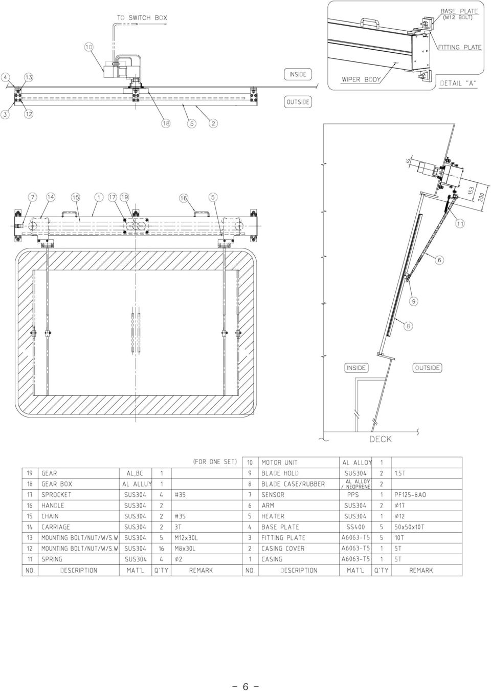
4 Casings (see fig. 1) The casing portion is composed of the main body case, chain, carriage. In case of case, corrosion-resistant aluminum casting material KS A6061 is used. The case also served as a guide rail on which the carriage plate runs. The crank rod, which in centered on the four roller carriage plate, in fixed to one point in the chain-belt which extends between driving and driven pulleys. The crank rod converts the rotary on the chain-belt into reciprocal motion, which causes the carriage to move between the upper and lower guide rails reciprocally. This motion in transmitted via the arm head and the arm to the blade, which thus wiper off rain and sea water Wiper arm (see fig. 1) The wiper arm which consists of the arm head, arm and blade is mounted to extend down ward from the carriage. Synthetic rubber is fitted on the blade and spring is provided in the bent portion between the arm head and the arm so that the rubber contacts the glass evenly. Adjust the blade pressure with this spring, as the force applied to the glass surface changes depending on the relation between the wiper fitting surface and the window glass surface Heater (see fig. 1) During navigation in cold weather, ice often forms between the carriage and casing, making the use of the wiper impossible. Therefore a heater is provided to melt the ice in the casing. This heater is designed exclusively for the wiper and is not for window glass. Note that this heater is not effective when the bladed is stuck frozen to the window glass. WARNING 1) When ambient temperature is blow 0, turn on heater switch first to allow unit to warm up for at least ten(10) minutes before turning on window wiper switch. 2) Turn off heater switch after the unit in full operation. 3) Don't operate the unit idly for long time Drawing & Part list - 3 -

5 Drawing & Part list - 4 -

6 * OUTSIDE MOTOR PART LIST

7 - 6 -
8 * INSIDE MOTOR TYPE PART LIST - 7 -

9 3-2. Control box - (Analog type) 1) POWER SWITCH This switch is used for electric power of main source ON/OFF. When select the off position, the operation is stopped after wiper is parking. 2) HEATER SWITCH The whole of wiper can be operased by operation. The heater is operated to intial statue automatically after one half hour. 3) LAMP Those brightness power and heater lamps are automatically operated by sensor in order to prepare at night and day. 4) SELECTOR SWITCH A) OFF : When this switch is set on the "OFF", wiper automatically return to the start position and stop wiping. B) INT. : This switch is device that wiper can be operated to intermitted speed. C) CONT. : This switch is device that wiper can be operated to various speed according to a speed switch. The rotating cycle is 16±5/min -> 32±5/min. 5) SPEED SWITCH This switch is device that is able to controller the wiping speed on INT. mode from 16±5/min -> 32±5/min. 6) INT. TIMER This switch is device that operate wiping time of wiper intermittently. The intermittent speed is controlled from 2 to 7 seconds. 7) MASTER SWITCH This switch is device that is able to move whole wiper at once. Just, wiper can not be moved at the state of "MASTER ON" individually, Push master switch once more and then push the individual switch, so that wiper can move individually. 8) INDIVIDUAL SWITCH This switch can operate each wiper individually. The individual wiping can be operated when the switch is just set but this switch can not use when master switch is "ON". WIPER CONTROL SERIES-803M - 8 -
 SELECTOR SWITCH A) OFF : When this switch is set on the \"OFF\", wiper automatically return to the start position and stop wiping. B) INT.")
10 4. Installation 4-1. Outside motor type CABLE GRAND HOLE(? 33) STROKE LENGTH + 250="M" "M"/ "M"/ BASE PLATE INSTALL POSITION BASE PLATE WINDOW CENTER LINE (Picture1) (Picture2) OUTSIDE MOTOR 1) Mark the vertical center line on the window.( 1marking) 2) Mark the horizontal center line for casing installation. Refer to "C" Arrangement drawing. 3) Mark "M/2" from the drawing and mark "+" 3 on the right left. Left side which is from distance 109mm center line.2 4) Mark tack welding4 vase plate on "+" marking position. upper and down side from the horizontal 5) Attach case of wiper on the base plate and then weld base plates finally. (full welding) 6) Bore 33hole after check cable gland hole carefully from the drawing. 7) Install wiper on the base plate4 that are full welding and then finish assembly with washer and nut. (Pls. refer to the above picture2) - 9 -
 Mark tack welding4 vase plate on \"+\" marking position.")
11 8) As showing picture, first disassemble wrench bolt of the wrench bolt and open the junction box cover. 9) Motor, heater and sensor line is supplied with connected by maker. 10) Connect yard 10c to the terminal block in junction box in accordance with the number of switch box. (Attention : Please, check very carefully if the heater and sensor lines are connected rightly otherwise it may cause a defect of sensor) 11) Please check again the connection line and assemble it again in reverse order. Wren bolt to be fasten firmly to prevent a water leakage. *ATTENTION (1) Motor 1 & heater2 sensor line3 to be connection by maker. (2) The connection work and line of supplying between controller and motor has to made by shipyard
 Motor 1 & heater2 sensor line3 to be connection by maker.")
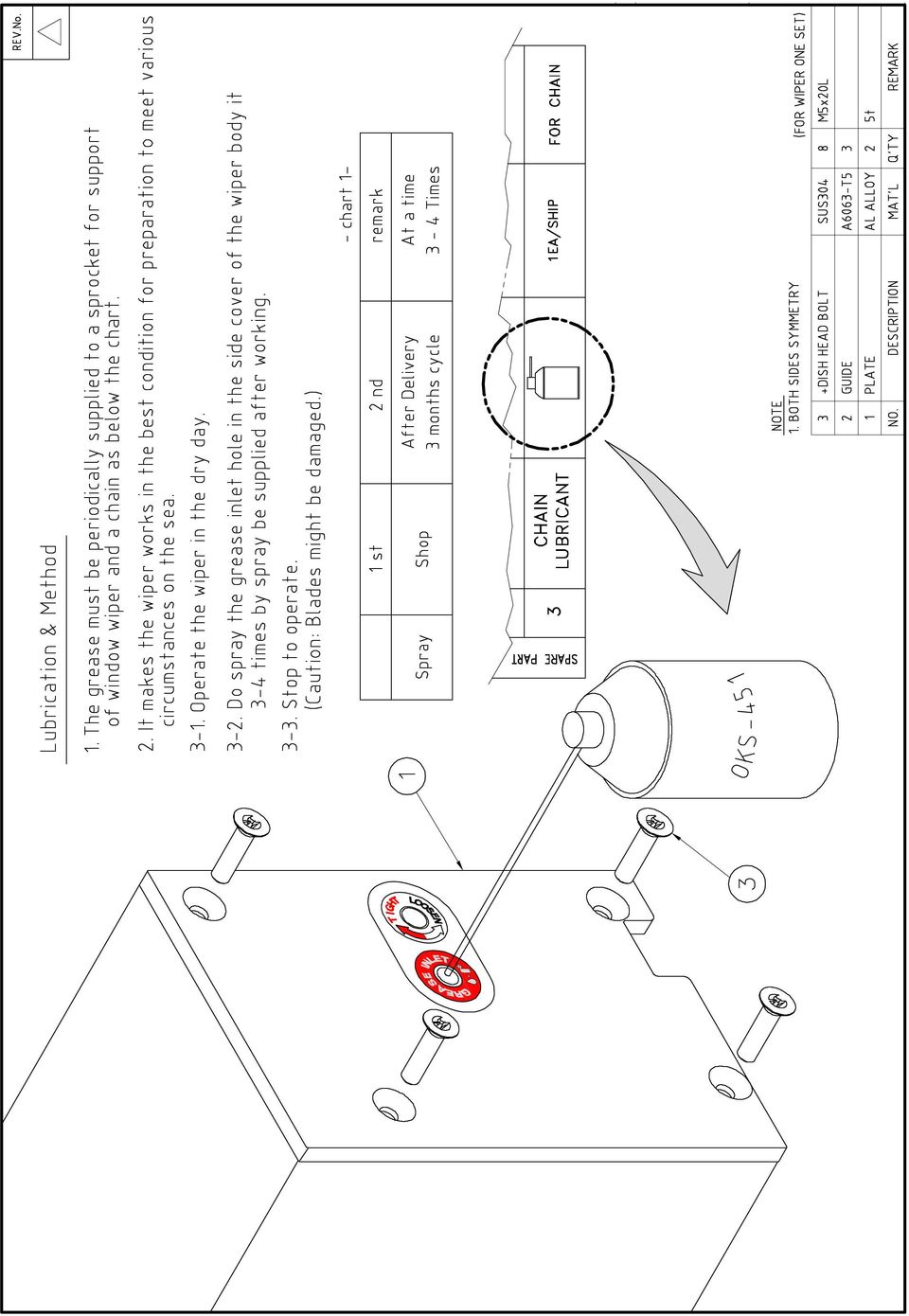
12 5. Maintenance and checking replacement parts The window wiper is adjusted at the factory before delivery. As it is maintenance free, no maintenance or checking is needed by user Motor unit Redial ball bearing are used in the motor and reduction gears and they are completely sealed and greases. There is no need to supply oil or grease. It is becomes necessary to change motor units, loosen the four bolts fixing the unit and replace the entire unit with a new one Wiper arm and blade To replace the wiper arm, loosen the two bolts holding the arm head on the carr -age. The blade is fitted at the arm end with blade fitting screws. By pulling out these screws, blade, arm be easily changed. Note that blade are consumables and be sure to replace worn-out or "UNEVEN" rubber with new when ones necessary. BLADE HOLD BOLT1 NUT1 BOL2 NUT2 Separated BLADE BLADE CHANGE METHOD 1. Untie the locked nut(1) slackly. 2. Untie the locked nut(2). 3. After remove the blade from blade hold. 4. Changed the blade after Nut(1),(2) tighten

13 5-3. Chain The chain is integrated with the rod when replacing the chain the rod also. The rod can be removed easily by loosening the nut of the rod pin fixed on the carriage plate. Change method of chain 1 Dissemble the damaged Chain from sprocket. 2 Untie the Connected nut & bolt from the carriage and separate the chain from carriage. 3 Exchanged the chain on the carriage. 4 Connect the chain to the sprocket Heater unit The heater unit is constructed separately from the wiper body for replacement, remove the fitting bolts of the heater. The entire unit can be dismounted in the way

14
15 6. Trouble shooting When a trouble occurs, remedy the trouble in accordance with the following procedure. Trouble Motor does not Speed regulation Motor works, but wiper work can not be made arm does not move Check power source Check wiring Check V-belt or Chain and rod Check wiring Check tacho generator Check carriage plate of motor Check motor Check variable resistor for speed setting Check speed Regulator unit Check speed Regulator unit

TECHNICAL INFORMATION
 TECHNICAL INFORMATION Models No. 2012NB Description 304mm (12") Automatic Thickness Planer CONCEPTION AND MAIN APPLICATIONS * Compact and light weight (27 Kg./59 lbs) automatic thickness planer for easier
Pallet Jack. OWNER S MANUAL Model MH1230. Important Safety Instructions Assembly Instructions Parts and Hardware Identification
 OWNER S MANUAL Model MH1230 Important Safety Instructions Assembly Instructions Parts and Hardware Identification Pallet Jack CAUTION: Read, understand and follow ALL instructions before using this product
WE-350 Series ¼ Turn Electric Actuator
 WE-350 Series ¼ Turn Electric Actuator Operation and Installation Manual Pg 1 (Rev. 020113) Table of Contents 1.0 General 1.1 Pre-Installation Inspection 1.2 Storage 1.3 Features & General Information
DIAMOND Retractable Rodding Robot Model SPRAYROD-R
 2004-12-21 2 1 (23) DIAMOND Retractable Rodding Robot Model SPRAYROD-R 2004-12-21 2 2 (23) Table of contents 1 TECHNICAL DESCRIPTION...4 1.1 MAIN DETAILS...5 1.2 COMPONENTS DESCRIPTION...5 1.2.1 Pneumatic
Operating Instructions Parts List Manual Scissor Lift Pallet Truck
 Operating Instructions Parts List Manual Scissor Lift Pallet Truck Note: Operator MUST read and understand this operating instructions before use this Hand Scissor Lift. Thank you for using this hand scissors
12. REAR WHEEL/BRAKE/SUSPENSION
 12 12 12-0 SERVICE INFORMATION... 12-1 REAR BRAKE... 12-5 TROUBLESHOOTING... 12-2 REAR SHOCK ABSORBER... 12-8 REAR WHEEL... 12-3 REAR FORK... 12-9 SERVICE INFORMATION GENERAL INSTRUCTIONS When installing
2003 ACCORD - Automatic Transmission Removal
 2003 ACCORD - Automatic Transmission Removal Special Tools Required Engine support hanger, A and Reds AAR-T-12566 Engine hanger balancer bar VSB02C000019 Front subframe adapter VSB02C000016 These special
INSTALLATION and OPERATION RANGE BALL CONVEYOR MODEL NO: BC-001AN
 Easy Picker Golf Products, Inc. 415 Leonard Blvd. N., Lehigh Acres, FL 33971 PH: 239-368-6600 FAX: 239-369-1579 Service: 800-982-4653 SALES: 800-641-4653 www.easypicker.com salesdept@easypicker.com INSTALLATION
Windshield Wiper System
 Volkswagen Golf 5 - Windshield Wiper System Volkswagen Technical Site: http://volkswagen.msk.ru http://vwts.info Page 1 / 15 92-1 Windshield Wiper System General information The windshield wiper system
SELF-STEERING AXLE TABLE OF CONTENTS
 SELF-STEERING AXLE TABLE OF CONTENTS Section 1 - Introduction Section 2 - Pre-Installation Check List Section 3 - Ride Height Adjustments Section 4 - Suspension Mount Section 5 - Axle Mount Section 6 -
T-Series Precision Linear Actuators Installation and Service Manual DW110353GB-1018 - EDITION 5. www.thomsonlinear.com
 T-Series Precision Linear Actuators Installation and Service Manual DW110353GB-1018 - EDITION 5 www.thomsonlinear.com Version History Edition Number Edition Date Reason for Revision 1 2004 First edition
Wiper Motor Marinco 2.5. Installation Instructions
 Wiper Motor Marinco 2.5 Installation Instructions Wiper Motor Marinco-2.5 The Marinco 2.5 Wiper Motor Offers the Following Features: Fully sealed base and housing which allows installation in outdoor wet
SERVICE PARTS LIST PAGE 1 OF 6 BASE ASSEMBLY SPECIFY CATALOG NO. AND SERIAL NO. WHEN ORDERING PARTS 12" DUAL BEVEL COMPOUND MITER SAW B27A
 PAGE 1 OF 6 BASE ASSEMBLY 00 0 EXAMPLE: Component Parts (Small #) Are Included When Ordering The Assembly (Large #). SPECIFY CATALOG NO. AND NO. WHEN ORDERING PARTS 1 02-80-0050 Thrust Bearing (1) 2 05-80-0510
Number Wheeler P/N Description Set Rex P/N Notes 1 603500 Base 1 J001 2 603501 Support, Right 1 J002 3 603502 Support, Left 1 J003 4 600328 Nut (M8)
") 1 603500 Base 1 J001 2 603501 Support, Right 1 J002 3 603502 Support, Left 1 J003 4 600328 Nut (M8) 4 5 600130 Spring Washer (8mm) 4 6 600344 Roll Pin (M6x30) 4 7 600129 Socket Hd Cap Screw (M8x25) 4 8
1 603500 Base 1 J001 2 603501 Support, Right 1 J002 3 603502 Support, Left 1 J003 4 600328 Nut (M8) 4 5 600130 Spring Washer (8mm) 4 6 600344 Roll Pin (M6x30) 4 7 600129 Socket Hd Cap Screw (M8x25) 4 8
LUCCI AIRFUSION QUEST II CEILING FAN
 LUCCI AIRFUSION QUEST II CEILING FAN WITH IR REMOTE INSTALLATION OPERATION MAINTENANCE WARRANTY INFORMATION CAUTION READ INSTRUCTIONS CAREFULLY FOR SAFE INSTALLATION AND FAN OPERATION. V1.0 QUEST II IR
AUTO TRANS DIAGNOSIS Article Text 1998 Volkswagen Passat This file passed thru Volkswagen Technical Site - http://volkswagen.msk.
 AUTO TRANS DIAGNOSIS Article Text 1998 Volkswagen Passat This file passed thru Volkswagen Technical Site - http://volkswagen.msk.ru ARTICLE BEGINNING 1997-98 AUTOMATIC TRANSMISSIONS Volkswagen Shift Interlock
Volkswagen Jetta, Golf, GTI 1999, 2000 2.8 Liter VR6 2V Engine Mechanical, Engine Code(s): AFP 17 Engine-Lubrication (Page GR-17)
: AFP 17 Engine-Lubrication (Page GR-17)") 17 Engine-Lubrication (Page GR-17) Lubrication system components, removing and installing Oil filter housing, disassembling and assembling Oil pan, removing and installing Oil pressure and oil pressure
17 Engine-Lubrication (Page GR-17) Lubrication system components, removing and installing Oil filter housing, disassembling and assembling Oil pan, removing and installing Oil pressure and oil pressure
Wipers and washers WINDSCREEN WIPERS. Intermittent variable delay
 Wipers and washers WINDSCREEN WIPERS S Do not operate the wipers on a dry screen. The drag on the wiper mechanism may cause damage. Before operating in freezing or very hot conditions, ensure that the
INSTRUCTIONS AND PARTS LIST FOR MODEL 70H & 75H HAND-OPERATED HYDRAULIC PRESS
 INSTRUCTIONS AND PARTS LIST FOR MODEL 70H & 75H HAND-OPERATED HYDRAULIC PRESS SETTING UP THE PRESS FOR OPERATION For shipping convenience, the gauge, pump handle, hoist crank, screw nose and base angles
Operating Manual. Los Angeles Abrasion Machine HM-70A & HM-70AF
 Operating Manual Los Angeles Abrasion Machine HM-70A & HM-70AF Rev: 07/19/2012 PHONE: 800-444-1508 P.O. Box 200, Lewis Center, Ohio 43035-0200 FAX: 800-255-5314 740-548-7298 E-mail: customerservice@gilsonco.com
This is the civilian transfer case with the cooling loop only found in the driven gear half of the front case.
 INTRODUCTION The Transfer case used in the AMG Hummer is a New Venture Gear, model 242. This case has been in use for the H-1/Hummer since the early 1990 s. There have been modifications to the internal
DANGER DANGER. General Information. Safety Is Your Responsibility. Ordering Parts. Contact Information
 Safety Safety Is Your Responsibility DANGER To avoid personal injury or death, carefully read and understand all instructions pertaining to the Anthony Liftgates product. Do not attempt to install, operate,
INSTRUCTION MANUAL. Black Angel. www.copterx.com. Features. Kit Helicopter. Copyright 2009 KY MODEL Company Limited.
 INSTRUCTION MANUAL Features - Carbon fiber main blade, tail blade, fly paddle, tail fin for extra weight saving and durability. - CNC machined high grade aluminum rotor head and tail gear box to ensure
Char-Lynn Hydraulic Motor. Repair Information. 10 000 Series. October, 1997
 Char-Lynn Hydraulic Motor October, 1997 Repair Information Geroler Motor Two Speed 001 27 Retainer inside bore of valve plate bearingless motors only 4 15 16 3 6 35 Parts Drawing 25 2 2 1 19 17 36 40 47
Front axle components, overview
 just a test. Front axle components, overview 40-1 General Information Load bearing components and parts of the suspension must not be welded or straightened. Vehicles without drive axle must not be moved,
Parts Required: Remove the Falcon Wiper Motor:
 INTERMITTENT WINDSHIELD WIPERS + 2 SPEEDS By Dick Harrington If you frequently drive your Falcon or Comet, sooner or later you will get caught in the rain. The first item of defense for good vision is
Original Assembly Guide
 TCT Multipurpose Single Bevel Sliding Compound Mitre Saw Original Assembly Guide Read instructions before assembling this tool. Table of Contents GB Assembly Guide Read instructions before assembling this
STEERING SYSTEM - POWER
 STEERING SYSTEM - POWER 1990 Nissan 240SX 1990 STEERING Nissan - Power Rack & Pinion Axxess, Maxima, Pulsar NX, Sentra, Stanza, 240SX, 300ZX DESCRIPTION The power steering system consists of a rack and
TABLE OF CONTENTS. I. TROUBLESHOOTING... 2 - Section 1.01: Common Problems/Solutions... 2
 BAL Accu-Slide System I. Table of Contents TABLE OF CONTENTS I. TROUBLESHOOTING... 2 - Section 1.01: Common Problems/Solutions... 2 II. GETTING STARTED... 5 - Section 2.01: Tools You Will Need... 5 - Section
13. REAR WHEEL/BRAKE/SUSPENSION
 13. REAR WHEEL/BRAKE/SUSPENSION 13 3.5~4.5kg-m 8.0~10.0kg-m 0.8~1.2kg-m 3.0~4.0kg-m 2.4~3.0kg-m 3.5~4.5kg-m 6.0~8.0kg-m 13-0 13. REAR WHEEL/BRAKE/SUSPENSION 13 REAR WHEEL/BRAKE/SUSPENSION SERVICE INFORMATION...
Windshield Wiper System
 Windshield Wiper System Page 1 / 17 92-1 Windshield Wiper System General information Caution! When disconnecting and reconnecting battery terminals, observe all applicable Notes and torque specifications,
STEERING HANDLEBAR/FRONT WHEEL/ FRONT SHOCK ABSORBER
 14 14 STEERING HANDLEBAR/FRONT WHEEL/ SCHEMATIC DRAWING ------------------------------------------------- 14-1 SERVICE INFORMATION------------------------------------------------ 14-2 TROUBLESHOOTING-----------------------------------------------------
Owners & Installation Manual for the Sheridan, Mountainair, Pine Valley and Old Forge Ceiling Fan Family
 Owners & Installation Manual for the Sheridan, Mountainair, Pine Valley and Old Forge Ceiling Fan Family Part of the Kiva Lighting Family Custom Lighting and Fans Since 1992 1312 12th St NW Albuquerque,
Volkswagen New Beetle 2.0 Liter 4-cyl General, Engine (Engine Code AEG) 17 Engine-Lubrication system (Page GR-17)
 17 Engine-Lubrication system (Page GR-17)") 17 Engine-Lubrication system (Page GR-17) Lubrication system components, removing and installing Oil pan, removing and installing Oil pressure and oil pressure switch, checking Dynamic oil pressure warning
17 Engine-Lubrication system (Page GR-17) Lubrication system components, removing and installing Oil pan, removing and installing Oil pressure and oil pressure switch, checking Dynamic oil pressure warning
Power Window/Power Lock Installation. To begin with you will need all the parts listed below:
 Power Window/Power Lock Installation To begin with you will need all the parts listed below: From Donor Fiero: Fiero power window regulators Power window motors (Generic GM type part) -motors are riveted
Parts#MB003-003 Reverse Gear MAMBA (Monoblock for Cable operated) For 5 speed Trans., '87 to '06 Big Twin models (except '06 Dyna)
 For 5 speed Trans., '87 to '06 Big Twin models (except '06 Dyna)") Installation Instructions Reverse Gear MAMBA (Monoblock for Cable operated) Read and become familiar with these installation instructions before start. Two Piece for H-D 5 Speed Trans., Cable operated
Installation Instructions Reverse Gear MAMBA (Monoblock for Cable operated) Read and become familiar with these installation instructions before start. Two Piece for H-D 5 Speed Trans., Cable operated
GEK-90214B. GE Lift Truck. User s Guide 144D2933G1 144D2912G1 144D2911G5
 g GEK-90214B GE Lift Truck User s Guide 144D2933G1 144D2912G1 144D2911G5 GE LIFT TRUCK EACH USER HAS THE RESPONSIBILITY TO INSTRUCT ALL PERSONNEL ASSOCIATED WITH THIS EQUIPMENT ON ALL SAFETY PRECAUTIONS
POSEIDON 2-29, 2-25 & 2-22 POSEIDON 2-29, 2-25 & 2-22 XT
 POSEION 2-29, 2-25 & 2-22 POSEION 2-29, 2-25 & 2-22 XT Repair Manual Index A. Safety precautions 3 B. Technical data 4 C. Structure 5-6. Service / Repair 7-23 E. Tools 24 F. Function 25-26 G. Electric
HYDRAULIC LIFT TABLE CART 2200-LB.
 HYDRAULIC LIFT TABLE CART 2200-LB. OWNER S MANUAL WARNING: Read carefully and understand all MACHINE ADJUSTMENT AND OPERATION INSTRUCTIONS before operating. Failure to follow the safety rules and other
6 inch A-Arm Lift Kit WARNING: 16-018/16-019. installation instructions. will fit CLUB CAR DS. included:
 Revised May 205 6-08/6-09 6 inch A-Arm Lift Kit will fit CLUB CAR DS installation instructions included: Rear Lift Blocks Main Suspension Assembly Spindles A-Arms Rear Shock Mounting Plates U-Bolts WARNING:
ASSEMBLY MANUAL SE-4S35
 Automatic drive ASSEBLY ANUAL SE-4S35 AI-4S35 SG-4R35 Battery box otor unit Inter-4 hub CONTENTS WARNING 1 INSTALLATION CONITIONS Battery box Speed sensor Cable lengths and diameters otor unit Recommended
ASSEMBLY DIAGRAM AND ASSEMBLY REFERENCE ULTIMA OLD SCHOOL 2 EVO & TC BELT DRIVE UNITS
 ASSEMBLY DIAGRAM AND ASSEMBLY REFERENCE ULTIMA OLD SCHOOL 2 EVO & TC BELT DRIVE UNITS BELT DRIVE ASSEMBLIES Part# 58-850 2 Old School Belt Drive Assembly - Polished Part# 58-851 2 Old School Belt Drive
AXLE SHAFTS - FRONT. 1998 Pontiac Bonneville MODEL IDENTIFICATION DESCRIPTION & OPERATION TROUBLE SHOOTING REMOVAL & INSTALLATION
 AXLE SHAFTS - FRONT 1998 Pontiac Bonneville 1998-99 DRIVE AXLES FWD Axle Shafts - Cars - "C", "G" & "H" Bodies GM Aurora, Bonneville, Eighty Eight, LeSabre, LSS, Park Avenue, Regency, Riviera MODEL IDENTIFICATION
TRANS-05, Torque Tube Removal, Rebuilding, and Installation
 TRANS-05, Torque Tube Removal, Rebuilding, and Installation Tools Metric Wrench Set Metric Socket Set Jack Stands (6 minimum) Floor Jack 8mm Cheesehead socket (also referred to as 12 point internal socket
PREASSEMBLED ELEMENTS FOR LIFTING AND SLIDING DOORS
 SYSTEM COMPONENTS PREASSEMBLED ELEMENTS FOR FIFTING AND SLIDING DOORS s r ood gn i d i l s dna gn i t f i f r o f s t neme l e de l bme s s ae r P PREASSEMBLED ELEMENTS FOR LIFTING AND SLIDING DOORS These
Model No: VS4815 1. SAFETY INSTRUCTIONS VS4800 2. INTRODUCTION & APPLICATIONS VS4815 3. CONTENTS. 2.1 Introduction. 2.
 Instructions for: Petrol Engine Twin Camshaft Setting / Locking Tool Kit - (incorporating Vanos Alignment) - BMW N42 & N46 Engines Model No: VS4800 Associated kit: Camshaft/Carrier Bracket Remover & Installer
P7100 PUMP INSTALLATION INSTRUCTIONS Diesel Care & Performance Inc
 P7100 PUMP INSTALLATION INSTRUCTIONS Diesel Care & Performance Inc Installation Timing Pin Location CAUTION: Before installing the injection pump, be sure that number 1 cylinder is at the Top Dead Center
 ABLOY DA60 SWING DOOR OPERATOR Installation and commissioning manual Abloy Oy An ASSA ABLOY Group company APPROVALS / STANDARDS Low Voltage directive 7//EEC as amended by the directive 9/68/EEC EMC directive
S OUNTING INSTRUCTION M M o u n t i n g k i t 2 &
 M O U N T I N G I N S T R U C T I O N S instructions This document is protected by copyright. The SICK AG company retains this right. Reproducing this document in whole or part is only permissible within
MODEL D GENERATOR COIL REPLACEMENT
 MODEL D GENERATOR COIL REPLACEMENT Materials Needed Procedure concept2.com 800.245.5676 (U.S. & Canada only) 0708 REPLACING THE MOUSE ON THE INDOOR ROWER 0409 TOOLS 5/32 7/16 or 11mm concept2.com 1. 2
Solstice/Sky Water Pump Replacement
 Solstice/Sky Water Pump Replacement The water pump on the Solstice/Sky is starting to need replacement on some vehicles. This guide will help in replacing the water pump while the engine is still in the
DIAMOND Gear Company, LTD. an ERIKS Company. Installation, Maintenance, & Operation Manual Declutchable Worm Gear
 DIAMOND Gear Company, LTD. an ERIKS Company Installation, Maintenance, & Operation Manual Declutchable Worm Gear 2016 DECLUTCHABLE WORM GEAR INSTRUCTIONS This is an instructional manual which provides
ARTICLE BEGINNING APPLICATION IDENTIFICATION DESCRIPTION LUBRICATION & ADJUSTMENT TROUBLE SHOOTING. MANUAL TRANSMISSIONS Saab 5-Speed Transaxle
 Article Text ARTICLE BEGINNING MANUAL TRANSMISSIONS Saab 5-Speed Transaxle APPLICATION TRANSMISSION APPLICATION ÄÄÄÄÄÄÄÄÄÄÄÄÄÄÄÄÄÄÄÄÄÄÄÄÄÄÄÄÄÄÄÄÄÄÄÄÄÄÄÄÄÄÄÄÄÄÄÄÄÄÄÄÄÄÄÄÄÄÄÄ Vehicle Application Transmission
Volkswagen B3 Passat General-Engine 4 CYL. 19 Engine - Cooling System (Page GR-19)
") 19 Engine - Cooling System (Page GR-19) Cooling system draining and filling general information Body components, layout Engine components, layout Radiator fan run-on checking Recommended mixture ratios
19 Engine - Cooling System (Page GR-19) Cooling system draining and filling general information Body components, layout Engine components, layout Radiator fan run-on checking Recommended mixture ratios
SLACK PERFORMANCE KARTS
 SLACK PERFORMANCE KARTS SET UP GUIDE Thank you for purchasing a 2013 Slack Axiom Chassis. Performance Mfg. strives to provide you with the very best chassis and components on the market today. Your satisfaction
2740 Whitten Rd Bldg 103 Memphis, TN 38133 Telephone 901-380-9290 Email Bwilliams@Dieselcare.net
 Fuel Injection Pump Replacement REMOVAL Diesel Care & Performance Inc 1. Disconnect negative battery terminal. 2. Remove throttle linkage. Fuel Injection Pump Bracket 3. Remove injection pump bracket.
2100 AD 015 0009 Mirror Elevator Ball Nut Replacement Procedure
 2100 AD 015 0009 Mirror Elevator Ball Nut Replacement Procedure Derek Guenther 1/28/2015 Rev. Purpose The purpose of this document is to describe the procedure necessary to replace one of the ball nuts
Installation & Maintenance Manual. Type D MKII Straight Line Wiper. With Pneumatic Motor
 Wynn Marine Ltd 2-4 Merse Road, North Moons Moat, Redditch, Worcestershire B98 9HL, United Kingdom Tel: +44 (0) 1527 61243, Fax: +44 (0) 1527 66836 Email: info@wynn.co.uk, website www.wynn.co.uk Installation
Volkswagen Jetta, Golf, GTI 1999, 2000 Brake System 46 Brakes - Mechanical Components (Page GR-46)
") 46 Brakes - Mechanical Components (Page GR-46) Front brakes Brake pads, removing and installing Brake pads, removing and installing FN 3 brake caliper, servicing FS III brake caliper, servicing Rear wheel
46 Brakes - Mechanical Components (Page GR-46) Front brakes Brake pads, removing and installing Brake pads, removing and installing FN 3 brake caliper, servicing FS III brake caliper, servicing Rear wheel
SET-UP AND INSTALLATION FOR LEAD SCREW CARTRIDGE ASSEMBLY
 SET-UP AND INSTALLATION FOR LEAD SCREW CARTRIDGE ASSEMBLY 82-13-1 O-Ring (Rear) The Lead Screw Assembly is shipped separately. Note: Install Electrical and Pneumatic Circuitry. Be Sure electrical and pneumatic
TRANSMISSION INSTALLATION CONTENTS
 A Regal Beloit Company TRANSMISSION INSTALLATION CONTENTS RICHMOND 6-SPEED AND SUPER STREET 5-SPEED WITH OVER DRIVE TRANS AM, CAMARO, CHEVELLE, GTO, CUTLASS, WITH T-10/MUNCIE....2 RICHMOND 6-SPEED 1963
INSTRUCTION MANUAL AND PARTS LIST MODEL 14-10
 VERTICAL BAND SAWS INSTRUCTION MANUAL AND PARTS LIST MODEL 1-10 DAKE/PARMA WHEN ORDERING PARTS GIVE COMPLETE SERIAL NUMBER OF MACHINE GIVE PART NUMBER AND NAME GIVE AMOUNT REQUIRED Unless the above data
758 Heavy-duty Ratchet Guy Wire Cutter
 INSTRUCTION MANUAL 758 Heavy-duty Ratchet Guy Wire Cutter Read and understand all of the instructions and safety information in this manual before operating or servicing this tool. Register this product
Number Wheeler P/N Description Set Rex P/N Notes
 1 607051 Base 1 A050 2 607052 Motor Cover 1 A052 3 600778 Socket Hd Cap Screw (M8x60) 2 4 607053 Scrap Receiver 1 A053 5 607054 Tank Upper Cover 1 A054 6 607055 Oil Pot 1 A055 7 607056 Strainer 1 A056
NO-FROST CUSTOMER SUPPORT INFORMATION INFORMATION ON THE NO-FROST TECHNOLOGY WHITE GOODS
 INFORMATION INFORMATION ON THE TECHNOLOGY The -Frost refrigerators are different from the other static refrigerators in terms of their operational system. In normal refrigerators, in the freezing section,the
Service Manual Rol-Lift
 R 2000 Service Manual Rol-Lift Series: T and E Developed by Generic Parts Service This manual is intended for basic service and maintenance of the Rol-Lift pallet jack. The pallet jacks you are servicing
EM 58. 19. REMOVE NO. 2 MANIFOLD STAY (a) Remove the bolt, nut and stay.
 Remove the bolt, nut and stay.") 57 ROVAL 1. DISCHARGE FUEL SYST PRESSURE (See page FU-9) 2. DISCONNECT CABLE FROM NEGATIVE BATTERY TERMINAL CAUTION: Wait at least 90 seconds after disconnecting the cable from the negative (-) battery
57 ROVAL 1. DISCHARGE FUEL SYST PRESSURE (See page FU-9) 2. DISCONNECT CABLE FROM NEGATIVE BATTERY TERMINAL CAUTION: Wait at least 90 seconds after disconnecting the cable from the negative (-) battery
Volkswagen B3 Passat Manual Transmission 02A 34 Manual Transmission - Controls, Assembly (Page GR-34) 02A 5-speed. Gearshift cable/lever installing
 02A 5-speed. Gearshift cable/lever installing") 34 Manual Transmission - Controls, Assembly (Page GR-34) 02A 5-speed Gearshift cable/lever installing Gearshift housing repairing Gearshift lever repairing lever/relay lever, installing Gearshift mechanism
34 Manual Transmission - Controls, Assembly (Page GR-34) 02A 5-speed Gearshift cable/lever installing Gearshift housing repairing Gearshift lever repairing lever/relay lever, installing Gearshift mechanism
Installation & Operation Manual. Type 1801 External Seahorse Pantograph Wiper. without Control System
 Wynn Marine Ltd Wynn House, Lansdown Estate, Cheltenham, GL51 8PL, United Kingdom Tel: +44 (0)1242 232266, Fax: +44 (0)1242 231131, Email: info@wynn.co.uk, website www.wynn.co.uk Installation & Operation
Instrument panel. Volkswagen Touareg - Instrument panel. Special tools, testers and auxiliary items required. Release lever T10039
 Volkswagen Touareg - Instrument panel Page 1 / 14 70-1 Instrument panel Tools Special tools, testers and auxiliary items required Release lever T10039 Instrument panel, removing and installing Removing
Fisher 1052 Size 20 Diaphragm Rotary Actuator with F and G Mounting Adaptation
 Instruction Manual 1052 Size 20 Actuator (F & G) Fisher 1052 Size 20 Diaphragm Rotary Actuator with F and G Mounting Adaptation Contents Introduction... 1 Scope of manual... 1 Description... 1 Specifications...
http://waterheatertimer.org/troubleshoot-rheem-tankless-water-heater.html
 http://waterheatertimer.org/troubleshoot-rheem-tankless-water-heater.html TECHNICAL SERVICE DEPARTMENT Removal, Cleaning, & Reinstallation of the Burner Assembly For models 74 & GT199 Required tools -
Operator s Manual EVENTER 20 / 25 Series Lifts
 Operator s Manual EVENTER 20 / 25 Series Lifts May 2013! Before operating this lift, read and understand this Operator s Manual. Become familiar with the potential hazards of this unit. Call SUMNER should
Installation, operation and maintenance manual TX 35A
 Installation, operation and maintenance manual TX 35A Rev.10 may 2012 Page 1 of 18 1.0.0 Table of contents INSTALLATION, OPERATION AND MAINTENANCE MANUAL...1 1.0.0 TABLE OF CONTENTS...2 2.0.0 ILLUSTRATIONS...2
Slide the new steering column shaft through the steering column from the driver compartment.
 Slide the new steering column shaft through the steering column from the driver compartment. Push the column shaft through the steering column until the machined end is out past the column lower bushing.
MONDOATHENS BASKETBALL SET (Reference PK110)
") MONDOATHENS BASKETBALL SET (Reference PK110) DESCRIPTION The MONDOATHENS backstop unit is mainly designed for multi-sports pavilions and installations where the highest-level basketball competitions are
MONDOATHENS BASKETBALL SET (Reference PK110) DESCRIPTION The MONDOATHENS backstop unit is mainly designed for multi-sports pavilions and installations where the highest-level basketball competitions are
TSB PART NAME PART NUMBER REMARK 56315-2H000FFF
 1 of 13 17.10.2008 г. 11:25 TSB Model Group TSB No. Cee'd [ED]() Steering System(61) KFE08-61-V040-ED Subject Published 5/23/2008 MDPS WORM SHAFT FLEXIBLE COUPLING REPLACEMENT TSB Type Field Fix Area &
Installation Guide. WSD-100 Wind Speed and Direction Sensor For XR5 Data Loggers. February, 2011
 WSD-100 Wind Speed and Direction Sensor For XR5 Data Loggers Installation Guide February, 2011 Pace Scientific Inc www.pace-sci.com Tel: 704-799-0688 sales@pace-sci.com 1 Disclaimer The following warranty
M A N U A L 13-10-05
 Documentation The following information sheets illustrate the description below: 12-WW01-4G-E Sectional view of the lance with main dimensions 12-W101-6G-E Sectional view of the head of the lance with
FOREWORD. Right and left as used throughout this manual are determined by facing the direction the machine will travel when in use.
 FOREWORD The purpose of this manual is to assist you in operating and maintaining your Flail mower. Read it carefully before operating and maintaining the Flail mower, it furnishes the specifications,
REMOVAL AND INSTALLATION
 303-01C-1 REMOVAL AND INSTALLATION Engine Body On Special Tool(s) Adapter For 303-D043 303-D043-02 or equivalent Special Tool(s) 303-01C-1 Turbocharger Lifting Bracket 303-1266 Wrench, Fan Clutch Nut 303-214
AXLE SHAFTS - FRONT. 1993 Toyota Celica DESCRIPTION REMOVAL, DISASSEMBLY, REASSEMBLY & INSTALLATION. 1993 DRIVE AXLES Toyota FWD Axle Shafts
 AXLE SHAFTS - FRONT 1993 Toyota Celica 1993 DRIVE AXLES Toyota FWD Axle Shafts Toyota; Celica DESCRIPTION Axle shafts transfer power from transaxle to driving wheels. All axle shafts consist of a shaft
1. SAFETY RULES WARNING TO REDUCE THE RISK OF FIRE, ELECTRIC SHOCK OR PERSONAL INJURY, MOUNT FAN TO OUTLET BOX MARKED "ACCEPTABLE FOR FAN SUPPORT".
 1 1. SAFETY RULES 1. To reduce the risk of electric shock, insure electricity has been turned off at the circuit breaker or fuse box before beginning. 2. All wiring must be in accordance with the National
1. Lay out 2 pieces of 7/8" tubing and mark for bending as shown. Remember that the bend is in the shaded area as shown below in Figure 1.
 MINI BIKE PLANS Page 1 INTRODUCTION Before starting to build your Mini-Bike, be sure that you have all the parts shown on the material list. You will note that tubing has been used in the construction.
Remote Head REMO ONE. Code 5750. Manual
 Remote Head REMO ONE Code 5750 Manual by sachtler. All rights reserved Version: 1.2/09/05 Issue date: September 2005 Order no.: srh20t010a We want you to receive Sachtler products that are always state
SECTION G2: CABLE PROCESSOR MODULE MAINTENANCE
 SECTION G2: CABLE PROCESSOR MODULE MAINTENANCE Cable Processor Module overview WARNING! When tipping the Cable Processor Module back, (after removing the toggle arm pin), use extreme caution not to drop
assembly instructions
 assembly instructions 1 // this guide is for Urban Chic gents & ladies. // this guide is for Urban Chic gents & ladies. 2 1 x ph screwdriver 2 x 10mm spanners 1 x 15mm spanners 1 x 13mm spanners 1 x 6mm
Hot-End Replacement Guide. BFB 3000 plus & 3D Touch
 Hot-End Replacement Guide BFB 3000 plus & 3D Touch Pre assembly checks: Testing the hot-end before fitting: Check the heating cable: Set the multi-meter to read resistance (2000 ohms) Test the two outside
300 SERIES 331, 332, 333, 344, 356 AND 367 MODELS
 Section: MOYNO 500 PUMPS Page: 1 of 8 Date: March 1, 1998 SERVICE MANUAL MOYNO 500 PUMPS 300 SERIES 331, 332, 333, 344, 356 AND 367 MODELS Mechanical Seal Models Packing Gland Models MODELS DESIGN FEATURES
EZ-Steer Assisted Steering System
 EZ-Steer Assisted Steering System Installation Instructions Platform Kit P/N 53059-54 Case IH CVX 1135 CVX 1145 CVX 1155 CVX 1170 CVX 1190 CVX 1195 CVX 135 CVX 145 CVX 155 CVX 175 CVX 195 New Holland TVT
EC DECLARATION OF CONFORMITY FOR MACHINES
 EC DECLARATION OF CONFORMITY FOR MACHINES (DIRECTIVE 98/37/EC) Manufacturer: Address: Declares that: FAAC S.p.A. Via Benini, 1-40069 Zola Predosa BOLOGNA - ITALY 770 mod. operator is built to be integrated
Manual for GlobePharma Mini-Press II Rotary Tablet Press
 1 of 13 Preparing the Rotary Press 1. Make sure the rotary press is unplugged. 2. Open the bottom cabinet of the rotary press and take out the grey tool kit, and the beige box of punches and dies. 3. Take
Guide for Installation and Maintenance of MacroAir (ME Series) High Volume Low Speed Fans
 High Volume Low Speed Fans") Guide for Installation and Maintenance of MacroAir (ME Series) High Volume Low Speed Fans Version 9.0 April 2014 1 Delivery: Upon receipt of fans, thoroughly inspect units for any damage sustained during
Guide for Installation and Maintenance of MacroAir (ME Series) High Volume Low Speed Fans Version 9.0 April 2014 1 Delivery: Upon receipt of fans, thoroughly inspect units for any damage sustained during
CAM-03, Camshaft Assembly Oil Seal Replacement
 CAM-03, Camshaft Assembly Oil Seal Replacement Tools Jack stands Floor Jack Metric Socket set Metric Wrench set Porsche Timing Belt Tension tool (P9201) Flywheel Lock (P9206) Balance Shaft Pin Spanner
CHAPTER 65 TAIL ROTOR DRIVE SYSTEM. Section Title Page
 CHAPTER 65 TAIL ROTOR DRIVE SYSTEM Section Title Page 65-00 Description........................................ 65.1 65-10 Tail Rotor Drive Fan Shaft.............................. 65.1 65-20 Tail Rotor
2008 ACCORD - Front Knuckle/Hub/Wheel Bearing Replacement (page 18-13)
") 2008 ACCORD - Front Knuckle/Hub/Wheel Bearing Replacement (page 18-13) Exploded View Special Tools Required Ball joint remover, 28 mm 07MAC-SL0A202 Hub dis/assembly tool 07GAF-SD40100 Bearing driver attachment,
2008 ACCORD - Front Knuckle/Hub/Wheel Bearing Replacement (page 18-13) Exploded View Special Tools Required Ball joint remover, 28 mm 07MAC-SL0A202 Hub dis/assembly tool 07GAF-SD40100 Bearing driver attachment,
VEHICLE SPEED CONTROL SYSTEM
 PL VEHICLE SPEED CONTROL SYSTEM 8H - 1 VEHICLE SPEED CONTROL SYSTEM TABLE OF CONTENTS page DESCRIPTION AND SPEED CONTROL SYSTEM...1 SPEED CONTROL SERVO-PCM OUTPUT....2 SPEED CONTROL SWITCHES PCM INPUT...2
Fuel Injection Pump, Rotary (005-014)
") Fuel Injection Pump, Rotary View Related Topic Page 1 of 30 Fuel Injection Pump, Rotary (005-014) Table of Contents Summary General Information Preparatory Steps Remove Front Gear Train Rear Gear Train
Fuel Injection Pump, Rotary View Related Topic Page 1 of 30 Fuel Injection Pump, Rotary (005-014) Table of Contents Summary General Information Preparatory Steps Remove Front Gear Train Rear Gear Train
POWERS Controls No. 4 Pneumatic Damper Actuator
 POWERS Controls No. 4 Pneumatic Damper Actuator Technical Instructions Document No. 155-032P25 AP 331-2 Actuator Assembly 331-2929 Typical Actuator Assembly 331-2904 Typical Actuator Assembly 331-3000
6-years/75,000 miles Comprehensive coverage Subsequent Owner Warranty $100 Deductible
 LINCOLN PREMIER LIMITED WARRANTY 6-years/75,000 miles Comprehensive coverage Subsequent Owner Warranty $100 Deductible Comprehensive Coverage Because Lincoln has always been a brand you can trust and respect,