Declaration of Conformity.
|
|
|
- Dwain Morris
- 8 years ago
- Views:
Transcription

1 Declaration of Conformity. Type of equipment Brand Name /Trade Mark Type designation /model Applicant Network Camera SAMSUNG SND-5083P SAMSUNG TECHWIN CO., LTD. In accordance with the following Directives 2004/108/EC The Electromagnetic Compatibility Directive Including amendments by the CE Marking Directive 93/68/EEC 2011/65/EU Restriction of the use of certain hazardous substances in electrical and electronic equipment (recast) The following harmonized European standards or technical specifications have been applied EN EN EN EN A22010 EN A12010 EN EN Limits and methods of measurement of radio disturbance characteristics of information technology equipment Product family standard Immunity requirements for components of fire, intruder and social alarm systems Electrostatic discharge immunity test Radiated, radio-frequency, electromagnetic field immunity test Electrical fast transient/burst immunity test Surge immunity test Immunity to conducted disturbances, induced by radio-frequency fields The CE Marking on the products and/or their packaging signifies that SAMSUNG TECHWIN CO., LTD. holds the reference technical file available to the European Union authorities. Place and date of issue Authorized Signatory #42 Seongju-Dong, Changwon-Shi, Kyungsangnam-Do,Korea / June 26, 2013 Name Jei Soon, Kang Title Principal Research Engineer Signature

2

3 Page 2 of 54 Contents 1. Applicant information Laboratory information Test system configuration Operation environment Measurement Uncertainty Description of E.U.T General information Product description Auxiliary equipments Test configuration Operating conditions Summary of test results Summary of EMI emission test results Summary of immunity test results Performance criteria Test results Conducted Emission Radiated Emission Electrostatic Discharge Radio Frequency Electromagnetic Fields Electric Fast Transient/BURST Surge Conducted Immunity E.U.T. photographs... 49

4 Page 3 of Applicant information Applicant SAMSUNG TECHWIN CO., LTD. Address #42 Seongju-Dong, Changwon-Shi, Kyungsangnam-Do, Korea Telephone Fax js2002.kang@samsung.com Contact name Kang Jei Soon Manufacturer#1 SAMSUNG TECHWIN CO., LTD. Address #42 Seongju-Dong, Changwon-Shi, Kyungsangnam-Do, Korea Telephone Fax js2002.kang@samsung.com Contact name Kang Jei Soon Manufacturer#2 Address TIANJIN SAMSUNG TECHWIN OPTO-ELECTRONIC CO., LTD No.11 Weiliu Road. Micro-Electronic Industrial Park Jingang Road Tianjin , China


5 Page 4 of Laboratory information Address EMC compliance Ltd Sin-dong, Yeongtong-gu, Suwon-city, Gyeonggi-do, , Korea Telephone Number Facsimile Number FCC CAB. KR0040 VCCI Registration No. R-3327, G-198, C-3706, T-1849 Industry Canada Registration No. 8035A KOLAS NO. 231 SITE MAP Suwon city EMC compliance

6 Page 5 of Test system configuration 3.1 Operation environment Temperature Humidity Pressure Chamber(10 m) 26 C 39 % R.H. - Shielded room(ce) 28 C 36 % R.H. - Shielded room(esd) 26 C 48 % R.H kpa Test site These testing items were performed following locations; Test item Test site Conducted Emission Shielded Room Radiated Emission 10 m Chamber Harmonics current Immunity area Voltage fluctuations and flickers Immunity area Electrostatic discharge Shielded Room Radiated RF immunity Fully anechoic chamber (3 m) Electric Fast Transient/BURST Shielded Room Surge Shielded Room Conducted RF immunity Shielded Room Voltage dip/interruption Shielded Room Mains supply voltage variations Shielded Room
 Electric Fast")
7 Page 6 of Measurement Uncertainty All measurements involve certain levels of uncertainties, especially in field of EMC. The factors contributing to uncertainties are test receiver, cable loss, antenna factor calibration, Antenna directivity, antenna factor variation with height, antenna phase center variation, antenna frequency interpolation, measurement distance variation, site imperfection, mismatch, and system repeatability. Based on CISPR , the measurement uncertainty level with a 95 % confidence level was applied. Conducted emission measurement (C.L Approx 95 %, k = 2) Shielded Room (CE#1) Shielded Room (CE#2) Shielded Room (CE#3) 9 khz ~ 150 khz ± 3.82 db 150 khz ~ 30 MHz ± 3.43 db 9 khz ~ 150 khz ± 3.82 db 150 khz ~ 30 MHz ± 3.43 db 9 khz ~ 150 khz ± 4.00 db 150 khz ~ 30 MHz ± 3.63 db Radiated Emission measurement (C.L Approx 95 %, k = 2) 10 m Chamber (#F4) 10 m Chamber (#F2) 30 MHz ~ 300 MHz 300 MHz ~ MHz 3 m db, db 10 m db, db 3 m db, db 10 m db, db 1 GHz ~ 6 GHz 3 m db, db 30 MHz ~ 300 MHz 300 MHz ~ MHz 3 m db, db 10 m db, db 3 m db, db 10 m db, db 1 GHz ~ 6 GHz 3 m db, db Radio Frequency Electromagnetic Fields (C.L Approx 95 %, k = 2) ± 1.82 db Disturbance power Electromagnetic Fields (C.L Approx 95 %, k = 2) ± 3.73 db


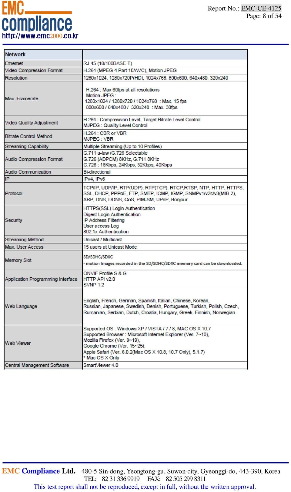
8 Page 7 of Description of E.U.T. 4.1 General information


9 Page 8 of 54

10 Page 9 of 54

11 Page 10 of Product description Type of product Model name (Basic) Network Camera SND-5083P Model name (Variant) - Difference - Trade name - Serial no Testing voltage Product rating Internal clock frequency Note Engineering Sample DC 12 V, PoE DC 12 V, PoE Above 108 MHz * AC/DC adaptor was not provided by the manufacturer. * PoE Switch was not provided by the manufacturer. 4.3 Auxiliary equipments Type Model / Part # Serial number Manufacturer Note PC SPARQ M53V NKW255EL000.B00380 HanSung computer Headset 1 SHS-250V - SAMSUNG Headset 2 SHS-250V - SAMSUNG USB Mouse Microsoft Micro SD Card (4GB) - - SanDisk AC/DC Adaptor (DC 12V) DAD 12050DKA - Dream Electronic PoE Switch FS108P 1DL20C3K00541 NETGEAR

12 Page 11 of Test configuration #1- DC 12V Note * Start End Cable Length Name I/O port Name I/O port Spec. (m) 1 Power AC/DC Adaptor Power 2.0 Non-Shield - 2 EUT LAN(RJ-45) Note PC LAN(RJ-45) 3.0 Non-Shield - (Network 3 Camera) Audio In/Out Headset 1 Audio In/Out 2.0 Non-Shield - 4 Micro SD Card Micro SD Card Micro SD Card Direct USB USB Mouse USB 1.8 Shield - Note PC 6 Audio In/Out Headset 2 Audio In/Out 2.0 Non-Shield - Cable

13 Page 12 of 54 #2- PoE Note * * Power supplied from PoE Switch Start End Cable Length Name I/O port Name I/O port Spec. (m) 1 EUT LAN(PoE) PoE Switch LAN(PoE) 3.0 Non-Shield - 2 (Network Audio In/Out Headset 1 Audio In/Out 2.0 Non-Shield - 3 Camera) Micro SD Card Micro SD Card Micro SD Card Direct LAN(RJ-45) PoE Switch LAN(RJ-45) 3.0 Non-Shield - 5 Note PC USB USB Mouse USB 1.8 Shield - 6 Audio In/Out Headset 2 Audio In/Out 2.0 Non-Shield - Cable 4.5 Operating conditions The EUT was configured as normal intended use. Test mode Normal operating 1 Camera monitoring test. (Web view) * Note 2 types of powers are available for the product, that are DC 12 V, PoE. Therefore, tests were performed for 2 different types of powers.

14 Page 13 of Summary of test results 5.1 Summary of EMI emission test results Applied Test items Test method Result Conducted Emission EN Complied Radiated Emission EN Complied Harmonics current EN A22009 N/A Voltage fluctuations and flickers EN N/A 5.2 Summary of immunity test results Applied Test items Test method Result * EN Electrostatic discharge EN Complied Radiated RF immunity EN A22010 Complied Electric Fast Transient/BURST EN A12010 Complied Surge EN Complied Conducted RF immunity EN Complied Voltage dip/interruption EN N/A Mains supply voltage variations EN N/A

15 Page 14 of Performance criteria The variety and the diversity of the apparatus within the scope of this document makes it difficult to define precise criteria for the evaluation of the immunity test results. If as a result of the application of the tests defined in this standard, the apparatus becomes dangerous or unsafe then the apparatus shall be deemed to have failed the test. A functional description and a definition of performance by the manufacture and noted in the test report, based on the following criteria Electrostatic discharge There shall be no damage, malfunction or change of status due to the conditioning. Flickering of an indicator during the application of discharge is permissible, providing which could be interpreted by associated equipment as a change, Radiated electromagnetic fields There shall be no damage, malfunction or change of status due to the conditioning. Flickering of an indicator during the application of discharge is permissible, providing which could be interpreted by associated equipment as a change, and no such Flickering of indicators occurs at a field strength of 3 V/m. For components of CCTV systems, where the picture is allowed at 10 V/m, providing. (a) there is no permanent damage or change to EUT (e.g. no corruption of memory or changes to programmable setting etc.) (b) at 3 V/m, any deterioration of the picture is so minor that the system could still be used; and (c) there is no observable deterioration of the picture at 1 V/m. Fast transient burst / slow high energy voltage surge There shall be no damage, malfunction or change of status due to the conditioning. Flickering of an indicator during the application of discharge is permissible, providing That there is no residual is permissible, providing that there is no residual change in the EUT or any change in outputs, which could be interpreted by associated equipment as

16 Page 15 of 54 Conducted RF immunity There shall be no damage, malfunction or change of status due to the conditioning. Flickering of an indicator during the application of discharge is permissible, providing That there is no residual is permissible, providing that there is no residual change in the EUT or any change in outputs, which could be interpreted by associated equipment as a change, and no such flickering of indicators oeuvres at U = 130 dbμv. For component of CCTV systems, where the status is monitored by observing the TV picture, then deterioration of the picture is allowed at U = 140 dbμv, providing (a) there is no permanent damage or change to the EUT (e.g. no corruption of memory or changes to programmable settings etc.) (b) at U = 130 dbμv, any deterioration of the picture is so minor that the system could still be used; and (c) there in no observable deterioration of the picture at U = 120 dbμv. Voltage dip/interruption / Voltage variation There shall be no damage, malfunction or change of status due to the conditioning. Flickering of an indicator during the conditioning is permissible, providing that there is no residual change in the EUT or any change in outputs, which could be interpreted by associated equipment as a change. The EUT shall meet the acceptance criteria for the functional test, after the conditioning.
 there is no permanent damage or")
17 Page 16 of Test results 6.1 Conducted Emission Test specification Testing voltage Test facility EN , Class A DC 12 V, PoE Shielded room (CE#2) Date Temperature ( C) 28 C Humidity (% R.H.) 36 % R.H. Remarks Complied Limits of conducted emission measurement AC main Frequency Class A (db(μv)) Class B (db(μv)) [MHz] Quasi-peak Average Quasi-peak Average 0.15 ~ ~ 56 * 56 ~ 46* 0.5 ~ ~ *The limit decreases linearly with the logarithm of frequency. Telecommunication Frequency [MHz] Class A Voltage Limits (db(μv)) Current Limits (db(μa)) Quasi-Peak Average Quasi-Peak Average 0.15 ~ to to to to ~ Frequency [MHz] Class B Limits (db(μv)) Current Limits (db(μa)) Quasi-Peak Average Quasi-Peak Average 0.15 ~ to to to to ~ * The limits decrease linearly with the logarithm of the frequency in the range 0.15 MHz to 0.5 MHz * The current and voltage disturbance limits are derived for use with an impedance stabilization Network (ISN) which presents a common mode (asymmetric mode) impedance of 150 Ω to the telecommunication port under test (conversion factor is 20 log /I = 44 db).
) Current Limits (db(μa)) Quasi-Peak Average Quasi-Peak Average 0.15 ~ 0.5 97 to 87 84 to 74 53 to 43 40 to 30 0.")
18 Page 17 of Measurement procedure The measurements were performed in a shielded room. EUT was setup as shown in photograph and placed on a non-metallic table height of 0.8 m above the reference ground plane. The rear of table was located 0.4 m to the vertical conducted plane. EUT was power through the LISN, which was bonded to the ground plane. The LISN power was filtered. Each EUT power lead, except ground (safety) lead was individually connected through a LISN to input power source. EUT signal cables that hung closer than 0.4 m to the Horizontal metal ground 0.3 m ~ 0.4 m long. The power cord was bundles in the center. All peripheral equipment was powered from a sub LISN. The LISN and ISN were positioned 0.8 m from the EUT. Peak and Average detection were used in preliminary testing and Quasi-peak and Average detections were used at final measurement. Both lines of power cord, hot and neutral, were measured Used equipments Equipment Model Serial No. Makers Next Cal. Date Used Test Receiver ESHS /011 R&S Test Receiver ESCI R&S Test Receiver ESCI R&S Test Receiver ESCI R&S LISN ENV R&S LISN L J20305 PMM - 8-WIRE ISN NTFM 8158 CAT5 CAT SCHWARZBECK WIRE ISN NTFM 8158 CAT3 CAT SCHWARZBECK ISN ST TESEQ ISN ENY R&S

19 Page 18 of Photographs of test setup * Telecommunication #1- DC 12V #2-PoE

20 Page 19 of Conducted emission measurement result * Telecommunication port #1- DC 12V _ LAN Port (LCL 55 db)_10 Mbps (SND-5083P) EMC Compliance.Ltd Shieldroom Serial Operator DC Power 12V Temp,Humidity [db(uv)] <<Conducted Emission>> Standard Model CISPR 22 Class A Remark1 Remark2 Remark3 Remark4 <CISPR22 A_TEL> Limit (QP) Limit (AV) <T_10> Spectrum (No Title1,AV) Spectrum (No Title1,PK) Suspected Item(No Title1) Final Item-QP(No Title1) Final Item-AV(No Title1) Level Frequency [MHz] Final Result --- No Title1 Phase --- No. Frequency Reading Reading c.f Result Result Limit Limit Margin Margin QP CAV QP CAV QP AV QP CAV [MHz] [db(uv)] [db(uv)] [db] [db(uv)] [db(uv)] [db(uv)] [db(uv)] [db] [db]

21 Page 20 of 54 #1- DC 12V _ LAN Port (LCL 65 db)_100 Mbps(SND-5083P) EMC Compliance.Ltd Shieldroom Serial Operator DC Power 12V Temp,Humidity [db(uv)] <<Conducted Emission>> Standard Model CISPR 22 Class A Remark1 Remark2 Remark3 Remark4 <CISPR22 A_TEL> Limit (QP) Limit (AV) <T_100> Spectrum (No Title2,AV) Spectrum (No Title2,PK) Suspected Item(No Title2) Final Item-QP(No Title2) Final Item-AV(No Title2) Level Frequency [MHz] Final Result --- No Title2 Phase --- No. Frequency Reading Reading c.f Result Result Limit Limit Margin Margin QP CAV QP CAV QP AV QP CAV [MHz] [db(uv)] [db(uv)] [db] [db(uv)] [db(uv)] [db(uv)] [db(uv)] [db] [db]
22 Page 21 of 54 #2- PoE _ LAN Port (LCL 55 db)_10 Mbps(SND-5083P) EMC Compliance.Ltd Shieldroom Serial Operator AC Power POE Temp,Humidity [db(uv)] <<Conducted Emission>> Standard Model CISPR 22 Class A Remark1 Remark2 Remark3 Remark4 <CISPR22 A_TEL> Limit (QP) Limit (AV) <T_10> Spectrum (No Title1,AV) Spectrum (No Title1,PK) Suspected Item(No Title1) Final Item-QP(No Title1) Final Item-AV(No Title1) Level Frequency [MHz] Final Result --- No Title1 Phase --- No. Frequency Reading Reading c.f Result Result Limit Limit Margin Margin QP CAV QP CAV QP AV QP CAV [MHz] [db(uv)] [db(uv)] [db] [db(uv)] [db(uv)] [db(uv)] [db(uv)] [db] [db]
23 Page 22 of 54 #2- PoE _ LAN Port (LCL 65 db)_100 Mbps(SND-5083P) EMC Compliance.Ltd Shieldroom Serial Operator AC Power POE Temp,Humidity [db(uv)] <<Conducted Emission>> Standard Model CISPR 22 Class A Remark1 Remark2 Remark3 Remark4 <CISPR22 A_TEL> Limit (QP) Limit (AV) <T_100> Spectrum (No Title2,AV) Spectrum (No Title2,PK) Suspected Item(No Title2) Final Item-QP(No Title2) Final Item-AV(No Title2) Level Frequency [MHz] Final Result --- No Title2 Phase --- No. Frequency Reading Reading c.f Result Result Limit Limit Margin Margin QP CAV QP CAV QP AV QP CAV [MHz] [db(uv)] [db(uv)] [db] [db(uv)] [db(uv)] [db(uv)] [db(uv)] [db] [db]
24 Page 23 of Radiated Emission Test specification Testing voltage Test facility Test distance EN , Class A DC 12 V, PoE 10 m Chamber (#F2) 10 m, 3 m Date Temperature ( C) 26 C Humidity (% R.H.) 39 % R.H. Remarks Complied Limits of radiated emission measurement Limits below 1 GHz Frequency [MHz] Class A 10 m Class B 10 m 30 ~ ~ Limits above 1 GHz Class 3 m Class 3 m Frequency Average limit Peak limit Average limit Peak limit [GHz] (db(μv/m)) (db(μv/m)) (db(μv/m)) (db(μv/m)) 1 ~ ~ Note - The lower limit applies at the transition frequency Measurement procedure The test was done at a 10 m chamber with a quasi-peak detector. EUT was placed on a non-metallic table height of 0.8 m above the reference ground plane. Cables were folded back and forth forming a bundle 0.3 m to 0.4 m long and were hanged at a 0.4 m height to the ground plane. Cables connected to EUT were fixed to cause maximum emission. Test was made with the antenna positioned in both the horizontal and vertical planes of polarization. The measurement antenna was varied in height above the conducting ground plane to obtain the maximum signal strength.
25 Page 24 of Used equipments Equipment Model no. Serial no. Makers Next Cal. Date Used Test Receiver ESCI R&S Test Receiver ESCI R&S Test Receiver ESCI R&S Bi-Log Antenna VULB SCHWARZBECK Amplifier 310N SONOMA INSTRUMENT db Attenuator 8491B HP Antenna Mast MA4000-EP 303 Innco Systems - Turn Table DT2000S-1t 079 Innco Systems - Amplifier 8449B 3008A02343 AGILENT Horn ANT ETS Spectrum Analyzer FSP R&S Sample calculation The field strength is calculated adding the antenna Factor, cable loss and, Antenna pad adding, subtracting the amplifier gain from the measured reading. The sample calculation is as follow Result = M.R + C.F(A.F + C.L +3 db Att A.G) M.R = Meter Reading C.F = Correction Factor A.F = Antenna Factor C.L = Cable Loss A.G= Amplifier Gain 3 db Att = 3 db Attenuator If M.R is 30 db, A.F 12 db, C.L 5 db, 3 db, A.G 35 db The result is = 15 db(μv/m)
26 Page 25 of Photographs of test setup * 30 MHz ~ 1 GHz (#1- DC 12V)
27 Page 26 of 54 * 1 ~ 6 (#1- DC 12V)
28 Page 27 of 54 * 30 ~ 1 (#2-PoE)
29 Page 28 of 54 * 1 ~ 6 (#2-PoE)
30 Page 29 of Radiated emission measurement result * Graph and Data * 30 ~ 1 (#1- DC 12V)_SND-5083P EMC Compliance Ltd. 10m Chamber <<Radiated Emission>> Model Serial Operator DC Power 12V Temp,Humidity [db(uv/m)] 60 Standard Remark1 Remark2 Remark3 Remark4 CISPR Pub.22 Class A 10m <CISPR 22 Class A> Limit(QP) <CE> Spectrum(H,PK) Spectrum(V,PK) Suspected Item(H) Suspected Item(V) Final Item(H,QP) Final Item(V,QP) 50 Level Frequency 1000 [MHz] Final Result No. Frequency [MHz] (P) V V V V V H V V Reading QP [db(uv)] c.f Result QP [db(1/m)] [db(uv/m)] Limit QP [db(uv/m)] Margin QP [db] Height [cm] Angle Remark [deg]
31 Page 30 of 54 * 1 ~ 6 (#1- DC 12V) _ SND-5083P <<Radiated Emission>> Model Serial Operator DC Power 12V Temp,Humidity [db(uv/m)] 90 Standard Remark1 Remark2 Remark3 Remark4 CISPR22 Class A GHz 3m <CISPR22 A GHz 3m> Limit(AV) Limit(PK) <12V_G> Spectrum(H,PK) Spectrum(V,PK) Suspected Item(H) Suspected Item(V) Final Item(H,AV) Final Item(H,PK) Final Item(V,AV) Final Item(V,PK) Level Frequency 6000 [MHz] Final Result No. Frequency [MHz] (P) H V H H V Reading AV [db(uv)] Reading PK [db(uv)] c.f Result AV [db(1/m)] [db(uv/m)] Result PK [db(uv/m)] Limit AV [db(uv/m)] Limit PK [db(uv/m)] Margin AV [db] Margin PK [db] Height Angle [cm] [deg] Remark
32 Page 31 of 54 * 30 ~ 1 (#2- PoE) _ SND-5083P EMC Compliance Ltd. 10m Chamber <<Radiated Emission>> Model Serial Operator AC Power POE Temp,Humidity [db(uv/m)] 60 Standard Remark1 Remark2 Remark3 Remark4 CISPR Pub.22 Class A 10m <CISPRA> Limit(QP) <CE> Spectrum(H,PK) Spectrum(V,PK) Suspected Item(H) Suspected Item(V) Final Item(H,QP) Final Item(V,QP) 50 Level Frequency 1000 [MHz] Final Result No. Frequency [MHz] (P) V V V V V V H H Reading QP [db(uv)] c.f Result QP [db(1/m)] [db(uv/m)] Limit QP [db(uv/m)] Margin QP [db] Height [cm] Angle Remark [deg]
33 Page 32 of 54 * 1 ~ 6 (#2- PoE) _ SND-5083P EMC Compliance Ltd. 10m Chamber <<Radiated Emission>> Model Serial Operator AC Power POE Temp,Humidity [db(uv/m)] 90 Standard Remark1 Remark2 Remark3 Remark4 CISPR22 Class A GHz 3m <CISPR22 A GHz 3m> Limit(AV) Limit(PK) <POE_G> Spectrum(H,PK) Spectrum(V,PK) Suspected Item(H) Suspected Item(V) Final Item(H,AV) Final Item(H,PK) Final Item(V,AV) Final Item(V,PK) Level Frequency [MHz] Final Result No. Frequency (P) Reading AV [MHz] [db(uv)] H V V V V 23.5 Reading PK [db(uv)] c.f Result Result Limit Limit AV PK AV PK [db(1/m)] [db(uv/m)] [db(uv/m)] [db(uv/m)] [db(uv/m)] Margin AV [db] Margin Height PK [db] [cm] Angle [deg]
34 Page 33 of Electrostatic Discharge Test specification EN Contact ± 6 Air ± 2, ± 4, ± 8 HCP ± 2, ± 4, ± 6 VCP ± 2, ± 4, ± 6 Test level 330 Ω / 150 Discharge impedance Number of discharge (Each polarity) Interval between discharges Contact 10 Air 10 HCP / VCP 10 1s Testing voltage DC 12 V, PoE Test facility Shielded room Date Temperature( C) 26 C Remarks Complied - There was no change of operation status during above testing. Humidity (% R.H.) 48 % R.H. Pressure ( ) Measurement procedure A ground reference plane was located on the floor, and connected to earth via a low Impedance connection. The return cable of the ESD generator was connected to the reference plane. In case of floor standing equipment, EUT was placed on the reference plane on 0.1 m of insulating Support. In case of table top equipment, EUT was placed on a wooden table 0.8 m above the reference grounded floor. A horizontal coupling plane (HCP) was placed on the table, and Connected to the reference plane via a 470 resistor located in each end (0.5 insulating support between EUT and HCP). In both cases a vertical coupling plane(vcp) OF 0.5 X 0.5 m was located 0.1 m from the EUT s sides. The VCP was connected to the reference plane in the same matter as the HCP Used equipments Equipment Model No. Serial No. Makers Next Cal. Date ESD Tester ESD Tester PESD 1600 NSG 437 H HAEFELY TESEQ HCP VCP Used
35 Page 34 of Photographs of test setup #1- DC 12V #2-PoE
36 Page 35 of Measurement result Electrostatic Discharge (Test Point) Air discharge Contact discharge #1- DC 12V
37 Page 36 of 54 #2-PoE
38 Page 37 of 54 #1- DC 12 V, #2- PoE HCP/VCP discharge Location(EUT) HCP (All 4 sides) VCP (All 4 sides) Applied level (±) ± 2, ± 4, ± 6 Result Complied Contact discharge Location(EUT) - Applied level (±) - Result - Applied level (±) ± 2, ± 4, ± 8 Result Complied Air discharge Location(EUT) A1 Enclosure(Case)
39 Page 38 of Radio Frequency Electromagnetic Fields Test specification EN A22010 Tested frequency 80 ~ 1, 1 ~ 2.7 Test level & Modulation 1 V/m, 3 V/m, 10 V/m, 80 % Amplitude Modulation (1 ) 1 V/m, 3 V/m, 10 V/m, Pulse Modulation (1 (0.5s ON 0.5s OFF)) Frequency Step log 1 % step Dwell time 3s Distance 3 m from EUT to tip of antenna Testing Voltage DC 12 V, PoE Test facility Fully anechoic chamber (3 m) Date Temperature( C) 25 C Remarks Complied - There was no change of operation status during above testing. Humidity (% R.H.) 47 % R.H. Pressure ( ) Measurement procedure The test was performed at 3 m full anechoic chamber. For floor standing equipment, the EUT was standing on the floor. For tabletop equipment, the EUT was located on a wooden table 0.8 m above the floor. The EUT was tested all sides, horizontal and vertical polarization.
40 Page 39 of Used equipments Equipment Model no. Serial no. Makers Next Cal. date Power meter PM AR Power sensor PH AR Power sensor PH AR Directional coupler DC AR Directional coupler DC7144M AR Signal generator E4421B GB AGILENT Amplifier BBA R&S Amplifier 60S1G3M AR Broadband Ant. LPDA Fiber Optic Modem HI-4413P - Antenna master - - ETS ETSLINDGREM ETS Used Photographs of test setup #1- DC 12 V
41 Page 40 of 54 #2- PoE Measurement result #1- DC 12 V, #2- PoE Location(EUT) Front side Rear side Left side Right side Antenna polarization Horizontal Vertical Horizontal Result Complied Complied Complied Vertical Horizontal Vertical Horizontal Vertical Complied Complied Complied Complied Complied
42 Page 41 of Electric Fast Transient/BURST Test specification EN A12010 Coupling DC 12 V Signal Clamp Telecommunication Clamp Test level DC 12 V ± 1 Peak Signal/Control ± 1 Peak Telecommunication ± 1 Peak Repetition frequency 100, Tr/Th = 5 / 50 Coupling time 60 s Testing Voltage DC 12 V, PoE Test facility Shielded room Date Temperature( C) 24 C Remarks Complied - There was no change of operation status during above testing. Humidity (% R.H.) 44 % R.H. Pressure ( ) Measurement procedure A ground reference plane was located on the floor. EFT generator was connected to reference ground plane via low impedance connection. For floor standing equipment, EUT was placed on a 0.1 m wooden table. For tabletop equipment, EUT was placed on a 0.1 m above the ground reference plane. Test generator and coupling/decoupling network was placed on, and bounded to, the ground reference plane. When using the coupling clamp, the minimum distance between the coupling plates and all other conductive surfaces, except the ground reference plane beneath the coupling clamp, Shall be 0.5 m Used equipments Equipment Model No. Serial No. Makers Next Cal. date Ultra compact simulator UCS 500 M6 V EM TEST Ultra compact simulator UCS 500 M EM TEST Capacitive Coupling Clamp - - EM TEST - Used
43 Page 42 of Photographs of test setup #1- DC 12 V

44 Page 43 of 54 #2- PoE Measurement result * DC Line (#1- DC 12 V) EFT coupling point (+) (-) Result DC 12 V + 1 kv - 1 kv Complied * Signal/Control EFT coupling point (+) (-) Result * Telecommunication (#1- DC 12 V, #2- PoE) EFT coupling point (+) (-) Result LAN(RJ-45) + 1 kv - 1 kv Complied LAN(PoE) + 1 kv - 1 kv Complied
45 Page 44 of Surge Test specification EN Coupling DC 12 V CDN Signal/Control CDN Test level DC 12 V ± 0.5, ± 1 Signal/Control ± 0.5, ± 1 Coupling Impedance Differential mode Ω Common mode 10 Ω + 9 Direct Surge pulse shape Tr/Th = 1.2 / 50 Number of surge 5 Coupling time 1 min Testing Voltage DC 12 V Test facility Shielded room Date Temperature( C) 24 C Remarks Complied - There was no change of operation status during above testing. Humidity (% R.H.) 44 % R.H. Pressure ( ) Measurement procedure A ground reference plane was located on the floor. SURGE generator was connected to reference ground plane via low impedance connection. For floor standing equipment & table top equipment, EUT was placed on a wooden table Used equipments Equipment Model No. Serial No. Makers Next Cal. date Ultra compact simulator UCS 500 M6 V EM TEST Ultra compact simulator UCS 500 M EM TEST CDN CNV 508 N1 V EM TEST Used
46 Page 45 of Photographs of test setup #1- DC 12 V Measurement result * DC Line (#1- DC 12 V) Coupling point (+) (-) Result DC 12 V + 0.5, , - 1 Complied Coupling point (+) (-) Result * Signal/Control
47 Page 46 of Conducted Immunity Test specification EN Tested frequency 0.15 ~ 100 Test level & Modulation 1 V, 3 V, 10 V, 80 % Amplitude Modulation (1 ) 1 V, 3 V, 10 V, Pulse Modulation (1 (0.5s ON 0.5s OFF)) Frequency Step log 1 % step DC 12 V CDN(M2) Signal/Control Clamp Telecommunication Clamp Coupling method Testing Voltage DC 12 V, PoE Test facility Shielded room Date Temperature( C) 24 C Remarks Complied - There was no change of operation status during above testing. Humidity (% R.H.) 44 % R.H. Pressure ( ) Measurement procedure A ground reference plane was located on the floor. The test was performed on a ground reference plane on a 0.1 m wooden table. This test were Performed using CDN for mains, clamp for signal and injection probe. The frequency range was swept from 0.15 to 100. This frequency range was Modulated with 1 sine wave at 80 %. The signal generators provided the modulated frequency at a 1 % step size. The power and all network cable, I/O cables longer than 3 m length were tested Used equipments Equipment Model no. Serial no. Makers Next Cal. date CS generator CWS 500 V EM TEST CS generator CWS500N1 V EM TEST CDN CDN L-801 M2/M EM TEST CDN CDN M2/M EM TEST Attenuator MU918 MCE/WEINSCHEL EM Clamp KEMZ Schaffner CDN CDN S1/ EM TEST Used
48 Page 47 of Photographs of test setup #1- DC 12 V
49 Page 48 of 54 #2- PoE Measurement result * DC Line (#1- DC 12 V) Coupling point Coupling method Result DC 12 V CDN(M2) Complied Coupling point Coupling method Result Coupling point Coupling method Result LAN(RJ-45) Clamp Complied LAN(PoE) Clamp Complied * Signal/Control * Telecommunication (#1- DC 12 V, #2- PoE)
50 Page 49 of E.U.T. photographs Front View Rear View
51 Page 50 of 54 Left View Right View
52 Page 51 of 54 Top View Bottom View
53 Page 52 of 54 Inside
54 Page 53 of 54 Main Board

55 Page 54 of 54 CCD Board
Declaration of Conformity.
 Declaration of Conformity. Type of equipment: Brand Name /Trade Mark: Type designation /model: Applicant: Network Camera SAMSUNG SND6011RP SAMSUNG TECHWIN CO., LTD. In accordance with the following Directives:
Declaration of Conformity.
 Declaration of Conformity. Type of equipment: Brand Name /Trade Mark: Type designation /model: Applicant: Network Camera SAMSUNG SNO-6011RP SAMSUNG TECHWIN CO., LTD. In accordance with the following Directives:
Declaration of Conformity.
 Declaration of Conformity. Type of equipment: Brand Name /Trade Mark: Type designation /model: Applicant: Network Camera SAMSUNG SNP-6200RHP SAMSUNG TECHWIN CO., LTD. In accordance with the following Directives:
Declaration of Conformity.
 Declaration of Conformity. Type of equipment: Brand Name /Trade Mark: Type designation /model: Applicant: PTZ CAMERA SAMSUNG SNP-5300P SAMSUNG TECHWIN CO., LTD. In accordance with the following Directives:
Declaration of Conformity.
 Declaration of Conformity. Type of equipment: Brand Name /Trade Mark: Type designation /model: Applicant: PTZ CAMERA SAMSUNG SCP2371HP SAMSUNG TECHWIN CO., LTD. In accordance with the following Directives:
Declaration of Conformity.
 Declaration of Conformity. 음 Type of equipment: Brand Name /Trade Mark: Type designation /model: Applicant: Digital Video Recorder SAMSUNG SRD-1656DP SAMSUNG TECHWIN CO., LTD. In accordance with the following
Declaration of Conformity.
 Declaration of Conformity. Type of equipment: Brand Name /Trade Mark: Type designation /model: Applicant: Network Camera SAMSUNG SND-5084RP SAMSUNG TECHWIN CO., LTD. In accordance with the following Directives:
Rated Power(W) 8W 2. EG-LED0840-01 8W 3. EG-LED1027-01 10W
 8W 2. EG-LED0840-01 8W 3. EG-LED1027-01 10W") 14713221 001 Seite 2 von 37 Page 2 of 37 Model List: No Model Rated Voltage(V) 1. EG-LED0827-01 Rated Power(W) 8W 2. EG-LED0840-01 8W 3. EG-LED1027-01 10W 4. EG-LED1040-01 AC 100-240V, 10W 5. EG-LED1027-02
14713221 001 Seite 2 von 37 Page 2 of 37 Model List: No Model Rated Voltage(V) 1. EG-LED0827-01 Rated Power(W) 8W 2. EG-LED0840-01 8W 3. EG-LED1027-01 10W 4. EG-LED1040-01 AC 100-240V, 10W 5. EG-LED1027-02
How To Read A Powerline From A Powerpoint Powerline To A Power Source
 Page: 2 of 71 Contents 1. Applicant information...3 2. Laboratory information...4 3. Test system configuration...5 3.1 Operation environment...5 3.2 Measurement Uncertainty...6 4. Description of E.U.T...7
SHENZHEN GEMBIRD ELECTRONICS LTD EMC REPORT
 Shenzhen BST Technology Co., Ltd. SHENZHEN GEMBIRD ELECTRONICS LTD EMC REPORT Prepared For : Product Name: Model : Prepared By : SHENZHEN GEMBIRD ELECTRONICS LTD 5th Floor, Building B, Shifeng Industry
TEST REPORT EN 55014-2 (1997) +A1 (2001)
 +A1 (2001)") Page 1 of 23 TEST REPORT EN 55014-2 (1997) +A1 (2001) Electromagnetic compatibility - Requirements for household appliances, electric tools and similar apparatus Part 2: Immunity Report Reference No....
Page 1 of 23 TEST REPORT EN 55014-2 (1997) +A1 (2001) Electromagnetic compatibility - Requirements for household appliances, electric tools and similar apparatus Part 2: Immunity Report Reference No....
Prepared for Dorman Long Engineering Technology Consultant (Shanghai) Co., Ltd.
 Co., Ltd.") www.ecmg-global.com EMC TEST REPORT On Model Name: DL-P40 Computer Control System Model Number: Release 3.0 Hardware and Software Brand Name: Dorman Long Technology Ltd. Trade Mark: DLT Prepared for Dorman
www.ecmg-global.com EMC TEST REPORT On Model Name: DL-P40 Computer Control System Model Number: Release 3.0 Hardware and Software Brand Name: Dorman Long Technology Ltd. Trade Mark: DLT Prepared for Dorman
FCC PART 15B CLASS A MEASUREMENT AND TEST REPORT
 FCC PART 15B CLASS A MEASUREMENT AND TEST REPORT For SAMBO HI TECH CO., LTD. 616-15, GANSUK4-DONG, NAMDONG-GU, INCHUN 405-810, KOREA Model: LSR700, SCI545HV1EF, SCI545HVEF This Report Concerns: Original
Test Report. Prepared for: Technologic Systems, Inc. Model: TS-8820
 Test Report Prepared for: Technologic Systems, Inc. Model: TS-8820 Description: Single Board Computer with Analog and Digital Inputs and Outputs, Relays, and RS-232/485 Ports To IEC 61000-6-1 (2005-03)
EMC TEST REPORT For. Shenzhen Homelux Security Equipment Co., Ltd. Auto Dialer. Model No.: HX-GD20
 EMC TEST REPORT For Shenzhen Homelux Security Equipment Co., Ltd Auto Dialer Model No.: HX-GD20 Prepared for : Shenzhen Homelux Security Equipment Co., Ltd Address : 4 th Floor, Building 5, Jiademaluan
Variant Model No. The equipment under test has found to be compliant with the applied standards. (Refer to the attached test result for more detail.
 EMC TEST REPORT Project No. LBE091881 Revision No. NONE Name of organization Samsung Electronics Co., Ltd. Applicant Address 416 Maetan 3-Dong,Yeongtong-Gu,Suwon-Si, Gyeonggi-Do, 443-742 Korea Date of
EMC TEST REPORT For. Webcam. Model Number: CAM67U
 EMC TEST REPORT For Webcam Model Number: CAM67U Prepared for : Gembird Europe B.V. Wittevrouwen 56, 1358CD Almere, The Netherlands. Phone: +31-36-5211588 Prepared By : Shenzhen Meihua Electronic Technology
EN 301 489-17 v1.2.1 TEST REPORT FOR. 802.11ag/Draft 802.11n WLAN PCI-E Mini Card MODEL NUMBER: BCM94322MC REPORT NUMBER: 07U11529-5
 EN 301 489-17 v1.2.1 TEST REPORT FOR 802.11ag/Draft 802.11n WLAN PCI-E Mini Card MODEL NUMBER: BCM94322MC REPORT NUMBER: 07U11529-5 ISSUE DATE: JANUARY 29, 2008 Prepared for BROADCOM CORPORATION 190 MATHILDA
Standard: EN 61000-4-2 :1995, EN 61000-4-3 :1996, ENV 50204 :1993, & EN 61000-4-4 :1995 Solid State Energy Meter
 Standard: EN 61000-4-2 :1995, EN 61000-4-3 :1996, ENV 50204 :1993, & EN 61000-4-4 :1995 Model: Solid State Energy Meter Prepared for: Analog Devices, Inc. 804 Woburn Street Wilmington, MA 01887 Date of
MYRICOM, INC. TEST REPORT FOR THE LAN INTERFACE CARD, M3F2-PCIXE-2
 MYRICOM, INC. TEST REPORT FOR THE LAN INTERFACE CARD, M3F2-PCIXE-2 EN55024 (1998), EN61000-3-2 (2001), EN61000-3-3 (1995 W/A1: 98), EN55022 (1998) CLASS A, CISPR 22 (1997) CLASS A & FCC PART 15 SUBPART
Test Report #: 1981-3 Date: April 8, 2005
 Test Report #: 1981-3 Date: April 8, 2005 CERTIFICATE #2316.01 Issued To: Bill Burks American Power Conversion 85 Rangeway Road North Billerica, MA 01862 USA 978-670-2440 Product Name/Description Model
TEST REPORT Rapporto di prova EMC N 060406. Test facility site: via L. da Vinci, 92, Caravaggio (BG), Italy Sede laboratorio
, Italy Sede laboratorio") TEST REPORT Rapporto di prova EMC N 060406 EUT: Organic Carbon Analyzer Analiuzzatore Carbonio Organico Model: TOCMETER Serial N : TM602 Client: TRE-ESSE s.r.l. Cliente Piazzale Europa 8 16036 Recco (GE),
TEST REPORT Rapporto di prova EMC N 060406 EUT: Organic Carbon Analyzer Analiuzzatore Carbonio Organico Model: TOCMETER Serial N : TM602 Client: TRE-ESSE s.r.l. Cliente Piazzale Europa 8 16036 Recco (GE),
MYRICOM, INC. TEST REPORT FOR THE SERVER RACK, 10G-PCIE2-8B2-2S & 10G-PCIE2-8B2-2QP FCC PART 15 SUBPART B SECTIONS 15.107 AND 15.109 CLASS A TESTING
 TESTING CERT #803.01, 803.02, 803.05, 803.06 MYRICOM, INC. TEST REPORT FOR THE SERVER RACK, 10G-PCIE2-8B2-2S & 10G-PCIE2-8B2-2QP FCC PART 15 SUBPART B SECTIONS 15.107 AND 15.109 CLASS A TESTING DATE OF
EMC Test for Compliance with EU EMC Directive 2004/108/EU
 EMC Test for Compliance with EU EMC Directive 2004/108/EU Partial Test 12-12-2012 Standards Description EN 55022:2011 Information technology equipment - Radio disturbance characteristics - Limits and methods
EMC TEST REPORT. Page: 1 of 38. Reference No.: WT08010091-S-E
 Page: 1 of 38 EMC TEST REPORT Reference No. Applicant Address : WT08010091-S-E : Gembird Electronics Ltd. : Room 1709 A, News Building, #2 Shennan Zhong Lu, Shenzhen, China Equipment Under Test (EUT) :
Electromagnetic Compatibility Test Report Test results of Floww equipment
 Electromagnetic Compatibility Test Report Test results of Floww equipment Reference number Status test report Brand Model number : 10C00357RPT01.doc : Final : Floww : mobilefloww screenfloww pocketfloww
CE-EMC TEST- REPORT TEST REPORT NUMBER: EFSN14040316E-E01 EUROFINS TESTING TECHNOLOGY (SHENZHEN) CO., LTD.
 CO., LTD.") EUROFINS TESTING TECHNOLOGY (SHENZHEN) CO., LTD. CE-EMC TEST- REPORT TEST REPORT NUMBER: EFSN14040316E-E01 Phone: +86-755-83585700 3A, F1.6, Tianfa Building, Tian an Cyber Park, Fax: +86-755-83585701 Futian
EUROFINS TESTING TECHNOLOGY (SHENZHEN) CO., LTD. CE-EMC TEST- REPORT TEST REPORT NUMBER: EFSN14040316E-E01 Phone: +86-755-83585700 3A, F1.6, Tianfa Building, Tian an Cyber Park, Fax: +86-755-83585701 Futian
TEST REPORT. CONCLUSION: The submitted sample was found to COMPLY with the test requirement
 TEST REPORT Applicant Address Shenzhen Gembird Electronics Ltd. 5F, Building B, Shi-Feng Industrial Zone, Hua-Ning Rd., Xin-Wei Village, Da-Lang Street, Long-Hua, Bao-An Area, Shenzhen 518109, Guangdong
Measurement of RF Emissions from a Final Coat Electronics Corrosion Module
 Engineering Test Report No. 37802-02 Rev. A Measurement of RF Emissions from a Final Coat Electronics Corrosion Module For : Canadian Auto Preservation, Inc. 390 Bradwick Drive Concord, Ontario CANADA
BioStation Mifare OC(BSM-OC) NONE. Receipt Date 21-Feb-08 Receipt Number. Issued Date 18-Mar-08 Tested Date
 NONE. Receipt Date 21-Feb-08 Receipt Number. Issued Date 18-Mar-08 Tested Date") Test Report for CE Report Number Applicant ESTCE0803-003 Company Name Address Product type Suprema Inc. 16F Parkview Office Tower, Jeongja-dong, Bundang-gu,Seongnam, Gyeonggi, 463-863 Korea FINGERPRINT
Test Report for CE Report Number Applicant ESTCE0803-003 Company Name Address Product type Suprema Inc. 16F Parkview Office Tower, Jeongja-dong, Bundang-gu,Seongnam, Gyeonggi, 463-863 Korea FINGERPRINT
CERTIFICATE. Issued Date:May. 18, 2006 Report No.: 065L043-IT-CE-P07V03. MGate MB318n(-T) (n=0~9,a~z)
 (n=0~9,a~z)") CERTIFICATE Issued Date:May. 18, 2006 Report No.: 065L043-IT-CE-P07V03 This is to certify that the following designated product Product Trade name Model Number : 1 Port Device Server : Moxa : NPort 5150(-T),
CERTIFICATE Issued Date:May. 18, 2006 Report No.: 065L043-IT-CE-P07V03 This is to certify that the following designated product Product Trade name Model Number : 1 Port Device Server : Moxa : NPort 5150(-T),
SGS-CSTC Standards Technical Services (Shanghai) Co., Ltd.
 Co., Ltd.") 588 West Jindu Road,Songjiang District,Shanghai,China Telephone: +86 (0) 21 6191 5666 Fax: +86 (0) 21 6191 5678 ee.shanghai@sgs.com Page: 1 of 23 1 Cover Page Application No.: Applicant: Manufacturer:
588 West Jindu Road,Songjiang District,Shanghai,China Telephone: +86 (0) 21 6191 5666 Fax: +86 (0) 21 6191 5678 ee.shanghai@sgs.com Page: 1 of 23 1 Cover Page Application No.: Applicant: Manufacturer:
Waveguide Access Point WGA631. Product Guide
 Waveguide Access Point Product Guide Waveguide Access Point Contents 1. Description............................ 3 2. Application............................ 3 3. Technical data... 4 4. Physical interfaces......................
ELECTROMAGNETIC COMPATIBILITY TEST. Report reference N R-255 EMC 2010
 ELECTROMAGNETIC COMPATIBILITY TEST Report reference N R-255 EMC 2010 Constructor. Address Reference person. C LUCE S.r.l. Via Marmolada 5/11 20060 Truccazzano (MI) Italy ---- Product....... Model......
FCC PART 15 SUBPART C EMI MEASUREMENT AND TEST REPORT
 FCC PART 15 SUBPART C EMI MEASUREMENT AND TEST REPORT For AeroComm, Inc. 10981 Eicher Drive Lenexa, KS 66219 2003-05-22 This Report Concerns: Original Report Equipment Type: 900MHz Transceiver Test Engineer:
EMC STANDARDS STANDARDS AND STANDARD MAKING BODIES. International. International Electrotechnical Commission (IEC) http://www.iec.
 http://www.iec.") EMC STANDARDS The EMC standards that a particular electronic product must meet depend on the product application (commercial or military) and the country in which the product is to be used. These EMC regulatory
EMC STANDARDS The EMC standards that a particular electronic product must meet depend on the product application (commercial or military) and the country in which the product is to be used. These EMC regulatory
R&S ENY81-CA6 Coupling Network For radio disturbance and immunity measurements
 R&S ENY81-CA6 Coupling Network For radio disturbance and immunity measurements on telecommunications ports Test & Measurement Data Sheet 01.00 R&S ENY81-CA6 Coupling Network At a glance The R&S ENY81-CA6
TEST REPORT. Please refer to section 3 of this report which indicates which item was actually tested and which were electrically identical.
 198 Kezhu Road, Scientech Park, Guangzhou Economic & Technological Development District, Guangzhou, China 510663 Telephone: +86 (0) 20 82155555 Fax: +86 (0) 20 82075059 Email: sgs_internet_operations@sgs.com
Electromagnetic Compatibility Test Report. DC DC umodule Regulator LTM4613
 Report No.: 0000091428 31160742.001 Page 1 of 36 Electromagnetic Compatibility Test Report Prepared in accordance with EN 55022: 2006, +A1: 2007 On DC DC umodule Regulator LTM4613 For Linear Technology
Report No. 091028R-RFCEP02V01. Test Report. MS-6633, VS12489, NetOn AP1900. Transmitter Module. MSI / MS-6894
 Test Report Product Name All in one PC Model No. Transmitter Module. MSI / MS-6894 MS-6633, VS12489, NetOn AP1900 Applicant Address MICRO-STAR INT L Co., LTD. No. 69, Li-De St., Jung-He City, Taipei Hsien,
Predicting radiated emissions from cables in the RE02/RE102/DO- 160/SAE J113-41 test set up, using measured current in NEC and simple TX equations.
 Predicting radiated emissions from cables in the RE02/RE102/DO- 160/SAE J113-41 test set up, using measured current in NEC and simple TX equations. D. A. Weston RE02Tx.rep 14-6-2004 NARTE Certified EMC
Cond-IS RF Conducted Immunity System
 Cond-IS RF Conducted Immunity System About RF Conducted Immunity In the global contest of EMC testing for residential and industrial EUTs (Equipments Under Test) RF Conducted Immunity compliance verification
LAB 1 TECHNICAL DOC 3 IN ONE LAB DEVICE. Velleman Legen Heirweg 33 9890 Gavere Belgium
 LAB 1 TECHNICAL DOC 3 IN ONE LAB DEVICE Velleman Legen Heirweg 33 9890 Gavere Belgium SPECIFICATIONS DIGITAL MULTIMETER 3 1/2 backlit LCD Automatic polarity indication DC voltage 200mV to 600V in 5 steps
Test result: SHENZHEN TIMEWAY TECHNOLOGY CONSULTING CO LTD. ISO/IEC17025Accredited Lab. Report No: FCC 1106180 File reference No: 2011-07-18
 Report No: FCC 1106180 File reference No: 2011-07-18 ISO/IEC17025Accredited Lab. Applicant: FUJIAN NAN AN BAOFENG ELECTRONICS CO., LTD Product: Model No: Trademark: Two Way Radio UV-3R BAOFENG Test Standards:
Current Probes. User Manual
 Current Probes User Manual ETS-Lindgren L.P. reserves the right to make changes to any product described herein in order to improve function, design, or for any other reason. Nothing contained herein shall
RAPPORTO DI PROVA / TEST REPORT
 RAPPORTO DI PROVA / TEST REPORT Rif./Ref.No. FCCTR_130738-0 Data / Date: 17/09/2013 Pagine / Pages : 15 Scopo delle prove /Test object : Richiedente / Applicant : Persona di riferimento / Applicant s referee
The EMI-Receiver according to CISPR 16-1-1
 Author: Dipl. -Ing. Dieter Schwarzbeck Schwarzbeck Mess-Elektronik An der Klinge 29 D-69250 Schönau / Germany Tel.: +49 6228 1001 Fax.:+49 6228 1003 support@schwarzbeck.de www.schwarzbeck.de Requirements
认 证 之 家 http://www.ait0769.com
 认 证 之 家 http://www.ait0769.com EUROPEAN STANDARD EN 55022 NORME EUROPÉENNE EUROPÄISCHE NORM September 2006 ICS 33.100.10 Supersedes EN 55022:1998 + A1:2000 + A2:2003 English version Information technology
Pre-Compliance Test Method for Radiated Emissions of Automotive Components Using Scattering Parameter Transfer Functions
 PreCompliance Test Method for Radiated Emissions of Automotive Components Using Scattering Parameter Transfer Functions D. Schneider 1*, S. Tenbohlen 1, W. Köhler 1 1 Institute of Power Transmission and
Rules for Classification and Construction Additional Rules and Guidelines
 VI Rules for Classification and Construction Additional Rules and Guidelines 7 Guidelines for the Performance of Type Approvals 2 Test Requirements for Electrical / Electronic Equipment and Systems Edition
EMC Expert System for Architecture Design
 EMC Expert System for Architecture Design EMC Expert System for Architecture Design Marcel van Doorn marcel.van.doorn@philips.com Philips Electromagnetics Competence Center High Tech Campus 26, 5656 AE
Telephone- and leased line modem for industrial applications TD-36
 Telephone- and leased line modem for industrial applications TD-36 Modem for industrial PSTN- and leased line applications The TD-36 is an analogue V.34 PSTN modem as well as an industrial 2-wire leased
UNDERSTANDING AND CONTROLLING COMMON-MODE EMISSIONS IN HIGH-POWER ELECTRONICS
 Page 1 UNDERSTANDING AND CONTROLLING COMMON-MODE EMISSIONS IN HIGH-POWER ELECTRONICS By Henry Ott Consultants Livingston, NJ 07039 (973) 992-1793 www.hottconsultants.com hott@ieee.org Page 2 THE BASIC
STRATO LED Drivers 70W, Single output
 Features STRATO switch mode driver technology is designed to generate one constant current output from a wide range AC input. The size and performance of these products make them the ideal choice for LED
RADIO TEST REPORT. EN 300 440-2 SRD radio equipment to be used in the 1 GHz to 40 GHz frequency range. DAkkS - Registration number : D-PL-12092-01-01
 RADIO TEST REPORT SRD radio equipment to be used in the 1 GHz to 40 GHz frequency range Report Reference No.... : G0M-1206-2043-TEU440G-V01 Testing Laboratory... : Eurofins Product Service GmbH Address...
RoHS APPROVAL SHEET. ituner 12V/6.6A SERIES NO. (E17) EA10953A. ( ) Edac Power Electronics (Suzhou) Co., Ltd. 59 No.59, Chang Sheng Road, Sheng Pu,
 EA10953A. ( ) Edac Power Electronics (Suzhou) Co., Ltd. 59 No.59, Chang Sheng Road, Sheng Pu,") APPROVAL SHEET CUSTOMER ituner CUSTOMER P/N DESCRIPTION EDAC MODEL 12V/6.6A SERIES NO. (E17) EA10953A DATE 2010-06-22 REVISION 0 APPROVED DESIGN PREPARE RoHS CONCLUSION APPROVED CONDITON CUSTOMER S APP
APPROVAL SHEET CUSTOMER ituner CUSTOMER P/N DESCRIPTION EDAC MODEL 12V/6.6A SERIES NO. (E17) EA10953A DATE 2010-06-22 REVISION 0 APPROVED DESIGN PREPARE RoHS CONCLUSION APPROVED CONDITON CUSTOMER S APP
COUPLING / DECOUPLING NETWORK (CDN) FOR UNSCREENED BALANCED PAIRS
 FOR UNSCREENED BALANCED PAIRS") IEC / EN 61000-4-6 specifies the design and performance of a range of coupling / decoupling networks (CDNs). Each CDN is specific to the type of cable and the intended signal carried on the cable. Teseq
IEC / EN 61000-4-6 specifies the design and performance of a range of coupling / decoupling networks (CDNs). Each CDN is specific to the type of cable and the intended signal carried on the cable. Teseq
Jens-EMC ApS. Randersvej 6 DK-8600 Silkeborg Denmark. EMC test report 2010-01-11-SeaCom. AC48/SeaCom1000 & AC128/SeaCom2100
 Jens-EMC ApS Randersvej 6 DK-8600 Silkeborg Denmark Test lab (+45) 86 84 91 66 Mobile(+45) 40 10 90 33 jko@jens-emc.dk www.jens-emc.dk CVR 27 21 47 62 EMC Consultancy EMC test report 2010-01-11-SeaCom
Applications in EMC testing. Outline. Antennas for EMC Testing. Terminology
 Antennas for EMC Testing Zhong Chen ETS-Lindgren 1301 Arrow Point Drive Cedar Park, TX 78613 Zhong.Chen@ets-lindgren.com Outline EMC Terms and Definitions Typical EMC Antennas Calibration of EMC Antennas
T200, PTP/IEEE 1588 Grandmaster Clock and
 T200, PTP/IEEE 1588 Grandmaster Clock and NTP Time Server with high accuracy GPS receiver, OCXO or Rubidium oscillator 1 Bd d Armor 22300 LANNION - FRANCE contact@heoldesign.com 1 HEOL-T200 : PERFORMANCE
Data Communications Competence Center
 Importance of Cable Balance For Improving Noise Susceptibility Data Communications Competence Center DCCC03101702 July 11, 2007 Summary In a study of category 5e and category 6 UTP cables, a strong correlation
Report No. 106262R-RFCEP76V01-A. Test Report. Model No. MS-AE12, AE2420 3D, MS-AE31 3D, MS-AE31, AE2420. Date of Receipt June 15, 2010
 Test Report Product Name All in one PC Model No. MS-AE12, AE2420 3D, MS-AE31 3D, MS-AE31, AE2420 Applicant MICRO-STAR INT'L Co., LTD. Address No. 69, Li-De St., Jung-He City, Taipei Hsien, Taiwan, R.O.C.
EMOSAFE EN-100. Network Isolators for PCB assembly 1 GENERAL DESCRIPTION. Product Data Sheet ENGLISH
 ENGLISH EMOSAFE EN-100 Product Data Sheet Network Isolators for PCB assembly November 2013 1 GENERAL DESCRIPTION The EMOSAFE EN-100 Network Isolator interrupts all galvanically conducting connections (conductors
30 In Compliance October 2014 www.incompliancemag.com
 30 In Compliance October 2014 www.incompliancemag.com Medical Devices in a Wireless World BY IVAYLO TANKOV While wireless technology is now an integral component of a wide variety of manufactured products,
DDX 7000 & 8003. Digital Partial Discharge Detectors FEATURES APPLICATIONS
 DDX 7000 & 8003 Digital Partial Discharge Detectors The HAEFELY HIPOTRONICS DDX Digital Partial Discharge Detector offers the high accuracy and flexibility of digital technology, plus the real-time display
AN96-07. Surging Ideas TVS Diode Application Note PROTECTION PRODUCTS. TRANSIENT IMMUNITY STANDARDS: IEC 61000-4-x
 TRANSIENT IMMUNITY STANDARDS: IEC 61000-4-x On January 1, 1996, exports into Europe began facing some tough transient immunity standards. The International Electrotechnical Commission (IEC), a worldwide
RX-AM4SF Receiver. Pin-out. Connections
 RX-AM4SF Receiver The super-heterodyne receiver RX-AM4SF can provide a RSSI output indicating the amplitude of the received signal: this output can be used to create a field-strength meter capable to indicate
Clamp Filters that Suppress Emission Noise Provide Immunity Against Surge Noise
 TDK EMC Technology Product Section Clamp Filters that Suppress Emission Noise Provide Immunity Against Surge Noise TDK Shonai Corporation Satoru Saito Reduce Emission Noise from Cables Even if an electronic
Agilent N8973A, N8974A, N8975A NFA Series Noise Figure Analyzers. Data Sheet
 Agilent N8973A, N8974A, N8975A NFA Series Noise Figure Analyzers Data Sheet Specifications Specifications are only valid for the stated operating frequency, and apply over 0 C to +55 C unless otherwise
Report No. 099096R-RFCEP76V01. Test Report. Product Name All in one PC Model No. MS-6657,AE2220 Transmitter Module Realtek / RTL8191SE
 Test Report Product Name All in one PC Model No. MS-6657,AE2220 Transmitter Module Realtek / RTL8191SE Applicant MICRO-STAR INT L Co., LTD. Address No. 69, Li-De St., Jung-He City, Taipei Hsien, Taiwan,
CE MARK TECHNICAL FILE AS/NZS EMC CONSTRUCTION FILE
 CE MARK TECHNICAL FILE AS/NZS EMC CONSTRUCTION FILE of Product Name Model Brand Memorex; Imation; TDK Life on Record Contains: 1. Declaration of Conformity 2. EN55022/CISPR 22, AS/NZS CISPR 22 EMI test
CE MARK TECHNICAL FILE
 CE MARK TECHNICAL FILE of WLAN 802.11ABG MINIPCI Model DCMA-81;CM10;VZA-82 Contains: 1. Declaration of Conformity 2. ETSI EN300 328 or/& ETSI EN301 893 test report 3. ETSI EN301 489-1 and ETSI EN301 489-17
15 Series - Electronic step relay and dimmer. Features 15.91 15.51 15.81 SERIE
 Series - Electronic step relay and dimmer SERIE Features.91.51.81 Electronic step relay and dimmer for control of lighting levels Suitable for incandescent and halogen lighting loads (with or without transformer
DATA SHEET DVI - HDCP Extension Cable
 DATA SHEET DVI - HDCP Extension Cable Contents Description Features Absolute Maximum Ratings Recommended Operating Conditions Electrical Power Supply Characteristics Receiver Electrical Interface Specifications
Coupling- / Decoupling Network. 150 khz 300 MHz. 150 khz 230 MHz. 10 khz 230 MHz. IEC 61000-4 - 6 and CISPR 15 / CISPR 22 IEC 61000-4 - 6
 Coupling- / Decoupling Network 150 khz 300 MHz IEC 61000-4 - 6 and CISPR 15 / CISPR 22 150 khz 230 MHz IEC 61000-4 - 6 10 khz 230 MHz IEC 61000-4 - 6 and IEC 61326-3 - 2 and NAMUR Coupling and decoupling
Energy Management Energy Meter Type EM23 DIN
 Energy Management Energy Meter Type EM23 DIN Class 1 (kwh) according to EN62053-21 Class B (kwh) according to EN50470-3 Class 2 (kvarh) according to EN62053-23 Accuracy ±0.5 RDG (current/voltage) Energy
CONTROLS DATA MANAGEMENT PROCESS AUTOMATION EUROCUBE. General purpose single phase thyristors and solid state relays Product data.
 425 CONTROLS DATA MANAGEMENT PROCESS AUTOMATION EUROCUBE General purpose single phase thyristors and solid state relays Product data abc 425 EUROCUBE A complete range of low cost solid state relays and
Verizon NEBS TM Compliance: Data Center Equipment NEBS Requirements Verizon Technical Purchasing Requirements VZ.TPR.9703 Issue 2, March 2012
 Verizon NEBS TM Compliance: Data Center Equipment NEBS Requirements Verizon Technical Purchasing Requirements VZ.TPR.9703 Issue 2, March 2012 CHANGE CONTROL RECORD: Version Date Action* Reason for Revision
R&S R-Line Compact Test Chamber Precise measurements of radiated emissions of wireless terminals 800 MHz to 18 GHz
 Test & Measurement Data Sheet 02.00 R&S R-Line Compact Test Chamber Precise measurements of radiated emissions of wireless terminals 800 MHz to 18 GHz R&S R-Line Compact Test Chamber At a glance The R-Line
Power-monitoring unit PowerLogic System. Technical data sheet. Power Meter Series 800
 Power-monitoring unit PowerLogic System Technical data sheet 2003 Power Meter Series 800 Function and characteristics PB100313 The PowerLogic Power Meter Series 800 offers all the high-performance measurement
Indoor / Outdoor Antenna
 z300 High Precision NTP Time Server Indoor / Outdoor Antenna High Precision NTP Time Server with PoE (Indoor or Outdoor use) synchronized by GPS Revision 4 ZTI / 1 boulevard d'armor / BP 20254 / 22302
CONDUCTED EMISSION MEASUREMENT OF A CELL PHONE PROCESSOR MODULE
 Progress In Electromagnetics esearch C, Vol. 42, 191 203, 2013 CONDUCTED EMISSION MEASUEMENT OF A CELL PHONE POCESSO MODULE Fayu Wan *, Junxiang Ge, and Mengxiang Qu Nanjing University of Information Science
TM7BDM8B expansion block - TM7 - IP67-8 DI/DO - 24V DC - 0.5 A - M8 connector
 Product datasheet Characteristics TM7BDM8B expansion block - TM7 - IP67-8 DI/DO - 24V DC - 0.5 A - M8 connector Main Range of product Product or component type Range compatibility Enclosure material Bus
TEST REPORT FROM RFI GLOBAL SERVICES LTD
 FROM RFI GLOBAL SERVICES LTD Partial Test of: BTM411 To: EN 300 328 V1.7.1 (2006-10) Test Report Serial No: RFI/RPT1/RP76018JD01A This Test Report Is Issued Under The Authority Of Brian Watson, Operations
AN003. Evaluation of Anechoic Chambers For EMC Measurements Using A CNE. Overview. CNE III 9kHz to 2GHz Conducted and radiated output
 Evaluation of Anechoic Chambers For EMC Measurements Using A CNE Overview Anechoic chambers are used for EMC testing primarily for radiated emissions (RE) and radiated immunity (RI) in the frequency range
NMI R 118 Testing Procedures and Test Report Format for Pattern Evaluation of Fuel Dispensers for Motor Vehicles (OIML R 118:1995(E), NEQ)
, NEQ)") Testing Procedures and Test Report Format for Pattern Evaluation of Fuel Dispensers for Motor Vehicles (OIM R 118:1995(E), NEQ) The English version of international standard OIM R 118:1995 Testing Procedures
Testing Procedures and Test Report Format for Pattern Evaluation of Fuel Dispensers for Motor Vehicles (OIM R 118:1995(E), NEQ) The English version of international standard OIM R 118:1995 Testing Procedures
Report Of. Shielding Effectiveness Test For. SafeSleeve Radiation Shielding Technology. Test Date(s): June 07 June 09, 2015
: June 07 June 09, 2015") Report Of Shielding Effectiveness Test For SafeSleeve Radiation Shielding Technology Test Date(s): June 07 June 09, 2015 Issue Date: June 10, 2015 UST Project No: 15-0137 Total Number of Pages Contained
Report Of Shielding Effectiveness Test For SafeSleeve Radiation Shielding Technology Test Date(s): June 07 June 09, 2015 Issue Date: June 10, 2015 UST Project No: 15-0137 Total Number of Pages Contained
Dual Chamber Temporary External Pacemaker
 5392 Dual Chamber Temporary External Pacemaker Electromagnetic Compatibility Declaration Caution: Federal law (USA) restricts this device to sale by or on the order of a physician. The following list includes
Electromagnetic Compatibility Considerations for Switching Power Supplies
 Electromagnetic Compatibility Considerations Characterization of the EMI problem requires understanding the interference source Switching power supplies generate Electromagnetic Interference (EMI) by virtue
Impedance 50 (75 connectors via adapters)
") VECTOR NETWORK ANALYZER PLANAR TR1300/1 DATA SHEET Frequency range: 300 khz to 1.3 GHz Measured parameters: S11, S21 Dynamic range of transmission measurement magnitude: 130 db Measurement time per point:
VECTOR NETWORK ANALYZER PLANAR TR1300/1 DATA SHEET Frequency range: 300 khz to 1.3 GHz Measured parameters: S11, S21 Dynamic range of transmission measurement magnitude: 130 db Measurement time per point:
Radiated Emission and Susceptibility
 Radiated Emission and Susceptibility Tzong-Lin Wu, Ph.D. EMC Lab Department of Electrical Engineering National Taiwan University Differential-Mode v.s. Common-mode Currents 1 Differential-Mode v.s. Common-mode
RF data receiver super-reactive ASK modulation, low cost and low consumption ideal for Microchip HCS KEELOQ decoder/encoder family. 0.
 Receiver AC-RX2/CS RF data receiver super-reactive ASK modulation, low cost and low consumption ideal for Microchip HCS KEELOQ decoder/encoder family. Pin-out 38.1 3 Component Side 1 2 3 7 11 13 14 15
CERTIFICATE OF CONFORMITY
 AIRBAKE ALL-CLAD ARNO CALOR CLOCK KRUPS LAGOSTINA MIRRO MOULINEX PANEX PENEDO REGAL ROCHEDO ROWENTA SAMURAI SEB SUPOR TEFAL T-FAL WEAREVER CERTIFICAT DE CONFORMITE CERTIFICATE OF CONFORMITY N DQNE-02-22611
NI USB-5681 RF Power Meter Specifications
 NI USB-568 RF Power Meter Specifications General This document lists specifications for the NI USB-568 RF power meter. Minimum or maximum specifications are warranted under the following conditions: hour
Low-cost EMI Pre-compliance Testing Using a Spectrum Analyzer
 Low-cost EMI Pre-compliance Testing Using a Spectrum Analyzer Application Note EMI regulations are in place throughout the world to provide improved reliability and safety for users of electrical and electronic
Single-phase (220...240 V) voltage monitoring: Undervoltage Overvoltage Window mode (overvoltage + undervoltage) Voltage fault memory selectable
 voltage monitoring: Undervoltage Overvoltage Window mode (overvoltage + undervoltage) Voltage fault memory selectable") Features 70.11 70.31 70.41 Electronic voltage monitoring relays for single and three-phase applications Multifunctional types, providing the flexibility of monitoring Undervoltage, Overvoltage, Window
Features 70.11 70.31 70.41 Electronic voltage monitoring relays for single and three-phase applications Multifunctional types, providing the flexibility of monitoring Undervoltage, Overvoltage, Window
Foxboro Evo Process Automation System
 Foxboro Evo Process Automation System Product Specifications PSS 31H-2Z32 FBM232 Field Device System Integrator Module, 10/100 Mbps Ethernet, Single The FBM232 Field Device System Integrator (FDSI) module
Design and Certification of ASH Radio Systems for Japan
 Design and Certification of ASH Radio Systems for Japan RFM s second-generation ASH radio hybrids are being used in a wide variety of applications in Japan, operating under the Japanese BIJAKU radio regulations.
How to Self-Certify For the CE Mark A Quick Start Guide by Dennis King - EMI Test Lab
 How to Self-Certify For the CE Mark A Quick Start Guide by Dennis King - EMI Test Lab For questions and details contact Dennis at dennis@emitestlab.com Introduction The CE mark (an acronym for the French
AMIS. Automated Metering and Information System. Integration of meters from other manufacturers
 AMIS Automated Metering and Information System TD-3530/TACU30 Third-Party Device Gateway Integration of meters from other manufacturers Connection and integration of max. 3 meters from third party manufactureres