MULTISTANDARD CMOS IC OF SINGLE CHIP PHONE WITH DOUBLE SOFT LIMITATION
|
|
|
- Eleanor Bennett
- 8 years ago
- Views:
Transcription
1 TECHNICAL DATA MULTISTANDARD CMOS IC OF SINGLE CHIP PHONE WITH DOUBLE SOFT LIMITATION Description IL2533N, IL2533D is CMOS IC, supporting all functions, necessary for design of electronic telephone with high characteristics. Standard application circuit is shown at figure 2. Device includes LD/MF constant automatic dialer, melodies generation, ring frequency identification and high quality circuit for line/speech. RAM at chip, intended for redialing of 31-digit number and memory elements, containing upto 21 symbols/data. Floating marker method enables to use LNR function under control of different РАВХ systems. Device contains volume control of hearing aid. Volume is controlled by VOL button (5.4dB) or " /+" button (plus 8.1/minus 5.4dB in 5 levels). Main features Line/speech circuit. LD/MF constant automatic dialer and tone ring at one 28-pin CMOS chip. Operational range 13 to 100 mа (decreasing upto 5 mа causes productivity deterioration). Soft limitation for elimination of drastic distortion. Controlling of received signal volume. Automatic line loss compensation. Low noise level (max 72 dbmp). Actual or complex impedance. Switching LD/MF dialing. Tone damper during programming. Redial of the last 31 digit number. Reference storage. Redial of busy line or previous connection. Pause button for applying to pause or waiting function. 3 pulse flashes: buttons, R1 100 ms, R2 280 ms and R3 375/600 ms. Active RC-filter on chip. Circuit of ring frequency determination. Three-tone melody generator LS MFL RI LI RO VDD VSS CS AGND STB M2 M1 CI LO LED FCI LCC HS/DP OSC R1 R2 R3 MODE R4 C4 C C1 C2 package pin out PACKAGE IL2533D assembly to 28-pin SO-package MS-013AE. IL2533N assembly to 28-pin DIP-package MS-011AB. 1

2 Versatility of the circuit provides possibility of variants selecting on circuit`s pin and several outer components. It allows adapting easily to the requirements of different standard (post, telephone and telegraph). Description of circuits` pins is shown at table 1. R2 La C1 SA1 L b R1 VD1 VT2 R9 VD5 R14 C5 R15 R17 C6 C7 VD6 R19 C11 VT1 VD2 R3 R4 R7 R6 R12 R8 VT3 R10 R11 R13 C4 VT4 CS V SS L1 Adaptation to line Power supply generating Masking on direct current V DD Tune generator Ring frequency determination C1 HS/DP Controlling logic LLC LS Line current reading Soft encrease Clock oscillator R1 STB AGND Генератор тона OSC MFL Sound RAM switch off Keyboard controller MODE С1 С2 С3 LED С4 RO M2 M1 R1 R2 R3 R4 C8 C9 C10 R20 R21 R5 VD3 VD4 C2 C3 LLC Hi SA2 LLC Off LLC Lo R18 AGND R16 SA3 Keyboard VD7 VD8 VD9 VD10 Figure 2 Typical application flow-chat 2

3 Table 1 Circuit pins description Pin Pin letter No symbol Function 01 LS Line current input. Input for line current determination (responsibility setup) 02 MFL MF level setup. For DTMF level setup can be used potential divider, connected from this pin to A GND and to V SS 03 RO Receipt output Output for controlling of dynamic hearing aid with impedance from 140 to 300 Оhm 04 V DD Positive supply voltage. Supply voltage output for circuit 05 A GND Analog ground, Analog ground for amplifiers 06 STB Balanced input side tone. Input for side tone suppression 07 CI Entire impedance output. For complex impedance, capacitor should be connected to this output 08 MO Melody output. Melody generator PWM-output for tone ring. When output not active, in Switch off state 09 LLC Line waste compensation. Selected output for loss compensation in line. LLC=A GND : mа; LLC=V DD : mа; LLC=V SS :no compensation 10 HS/DP Switch hook input and output of pulse dialing. Analog input/output, establishing by high switch hooks by off-hook and open drain set it in low state during interruptions for pulse dialing and flash pulses 11 OSC Oscillator input. Input for ceramic resonator (3.5 МHz) 12 MODE Input of mode denomination selection. Mode output Open Row 1 Row 2 Row 3 Row 4 Row 5 Function Interlocking number dialing LD mode, 10 pulse/s, 33/66ms LD mode, 10 pulse /s, 40/60ms LD mode, 20 pulse /s, 16/33ms LD mode, 20 pulse /s, 20/30ms LD mode, 10 pulse /s, 33/66ms. Temporary MF with tone on first button input " " Only MF, 82/82ms Only MF, 82/160ms Row 6 Row 7 Note Pulse/s pulses per second. During temporary MF : 82/160ms 13 C4 14 C3 15 C2 16 C1 Keyboard line. (see keyboard scheme at figure 3) 3

4 Table 1 continued Pin Pin letter No symbol Function 17 R4 Keyboard line. 18 R3 (see keyboard scheme at figure 3) 19 R2 20 R1 21 FCI Frequency comparator input. Schmitt flip-flop input for ring frequency determination 22 LED LED output driver. Output for LED control, blinking in Program / Mute state M1 M2 Microphone outputs Differential inputs for microphone (electret type) 25 CS Input of current shunting control. Given N-channel output with open drain controls outer shunting high capacity transistor for modulation of line voltage and for line shorting during period of pulse number dialing 26 V SS Negative supply connection 27 LI Line input. Input is used for power abstraction and (adjusting) of line current 28 RI Receipt input. Input for signal received *Note LD pulse number dialing; *MF frequency number dialing; *DTMF two-frequency dialing (often case of frequence dialing) Function selection (general table) Function Straight memory (single key) 4 Indirect memory (two key) 10 Redialing yes LNR key yes Insert by LNR pause key yes Pause key PS yes Р/М key or МТ Р/М Tone/Pulse key (Т/Р) yes Temporary MF key " " yes Automatic setup key (А D) yes Volumes keys (VOL, "-/+") yes Volume reset by off-hook yes Tone ring programming yes Pause duration flash R3 600m 4

5 KEYBOARD CONNECTING Keyboard connecting is shown at figure 3. Key closed, R ON MAX = 1 Ohm Key opened, R OFF MIN = 1 Ohm C1 C2 C3 C4 R1 R2 R3 R4 P/M * # R1 R2 R3 LNR VOL + - A B C D RP PS T/P M1 M2 M3 M4 MR Figure 3 Keyboard connecting Power-up set up On-chip voltage on preset circuit traces supply voltage V DD during receiver off-hook. When V DD increase reaches level approximately 1.2 V, preset circuit empties RAM. Direct current conditions Typical operational range is from 13 to 100 mа. Operational range by lowered effectiveness is from 5 to 13 mа (parallel operation). In operational range all functions are active. By line currents lower than 13 mа microcircuit provides additional decrease lower than 4.5 V in order to allow parallel operation (see fig. 4). Direct current characteristic (excluding diode bridge) determining by voltage to LI and R1 resistor by line currents higher than 13 mа by following form: V LS = V LI + I LINE R1 (1). Voltage at LI is 4.5 V in typical operational range. In dialing mode, speech scheme and inactive device parts is in mode of decreased power consumption with the purpose of current saving. CS output pulls up to Vss in order to connect outer shunting transistor for supporting of low voltage at LS output within periods forming. IMPEDANCE FOR ALTERNATING CURRENT Circuit impedance on alternating current is adjusting by outer components. Impedance can be actual and complex. Alternating-current resistance Z AC, Ohm, is determining according to following form Z AC = 33 Z 1 5
.")
6 (2) Z 1 direct current value should be 30 Ohm for maintaining of correct characteristics on direct current. Reverse damping and suppressing of side current can be set up not depending of each other. 8 (V) VL S 6 5 VL I Variable signals absence Line current (mа) 100 Figure 4 Direct current characteristics. Dependence of potentials at LI and LS outputs from line current SPEECH CIRCUIT Speech circuit consists of transmitting and receiving chains with double soft limitation, line attenuation compensation and side current suppression. TRANSMITTING Amplification of transmitting chain is 37 db for matched load line 600 Ohm from М1/М2 to LS (see test circuit at figure 5). Microphone input is differential input with input resistance 20 kohm. Soft limitation circuit limits output voltage at LI to 2 V PEAK (see figure 5). Increase front duration is 30mcs/6dB and decay front duration is 20mcs/6dB. When no-signal mode is active, during dialing or after Р/М key pressing, amplification coefficient is reducing by more than 60 db. RECEIVING Amplification coefficient of receiving circuit is 3 db for 600 Ohm of line load (test circuit at figure 5). Differential-mode signal RI and STB are receiving input. When no-signal mode is active during dialing, amplification coefficient decreases for more than 60 db. During DIMF dialing, supporting tone is applied to the receiver. DIMF signal is supporting tone, with level lower than minus 30 db relative to line signal. Pressing Volume key can change receiving amplification coefficient. VOL key gives raising 5.4 db and has two-state function, i.e. repetitive key pressing sets up initial value of amplification coefficient. As alternative can be used +/ keys. + key increases coefficient by 8.1 db in 3 levels, and key decreases by 5.4 db in 2 levels (general range 13.5 db). Volume is set to initial value by switch hook actuation. Soft limitation circuit adjust voltage at receipt output (RO) no more than 1V PEAK (see figure 6) It prevents from sharp distortion and acoustic impact. 6
.")
7 SIDE TONE Good side tone suppression can be reached by using of following equal Z Z BAL LINE Z Z 2 = (3). 1 Signal of side tone suppression is applied to STB input (see figure 8). LINE ATTENUATION COMPENSATION Line attenuation compensation is controlled by circuit output. When this mode is activated, transmission and receipt coefficient is decreasing by 6 db by line currents from 20 to 50 mа, when LLC = A GND, and by currents from 45 to 75 mа, when LLC corresponds to high state (@R1=30 Ом). Line attenuation compensation become disconnected, when LLC corresponds to low state (see figure 7). 7

8 24 M2 IL2533 FCI 21 LS 1 A 23 M1 10 мкф 30 Ом 100 мкф R0 RI STB Ом 10n 10V RL 600 Ом 1 мкф 6 ком LI 27 КТ 660А (КТ 3107 Б) 25 B 100 ком MULTI-STANDARD SINGLE CHIP TELEPHONE CS C4 C3 C2 C1 R1 R2 R3 R4 VSS 26 HS/DP 150 Ом 100 мкф G5 S ком SA G3 AGND 5 G P3 мa SW1 К1 G1 V P1 V P4 SW3 G2 К2 SW2 10 ком К3 MODE G6 T2 22 ком К5 10 нф 330 ком 10 нф T1 1 2 MFL мкф P/M * # R1 R2 R3 LNR Vol + - A B C D RP PS T/P M1 M2 M3 M4 MR КТ 521 (КТ3107Б) 47 ком 10 ком КТ 520 (КТ 3102Б) 1 мом 3.58 МГц 8 MO OSC 11 G CI 7 SA2 LED 22 1 ком 15 нф К4 4 VDD LLC 9 SW4 P2 мa 50 мкф x10 В G4 8
 47 ком 10 ком КТ 520 (КТ 3102Б) 1 мом 3.")
9 Figure 6 Soft limitation and distortion by receipt 1,2 12 AGC switching Output voltage of receipt circuit (RO), V PEAK 1,0 0,8 0,6 0,4 0,2 0 0,25 0,50 0,75 1,00 1,25 VRO Line current 20 mа Frequency 800 Hz Distortion 1,50 1, ,00 Distortion Input line voltage (LS), V PEAK Tx ( db ) LLC = A GND f = 800 Hz Z LINE = 600 Ohm = -10 dbm V LS LLC = V DD LLC = V SS Current of line (ma ) Typical characteristics and line attenuation compensation for transmitting circuit Rx ( db ) f = 800 Hz Z LINE = 600 Ohm = -10 dbm V LS LLC = A GND LLC = V DD LLC = V SS Current of line (ma ) Typical characteristics and line attenuation compensation for receiving circuit Figure 7 Typical characteristics and line attenuation compensation 9
 Typical characteristics and line attenuation compensation for receiving circuit Figure 7 Typical characteristics and")
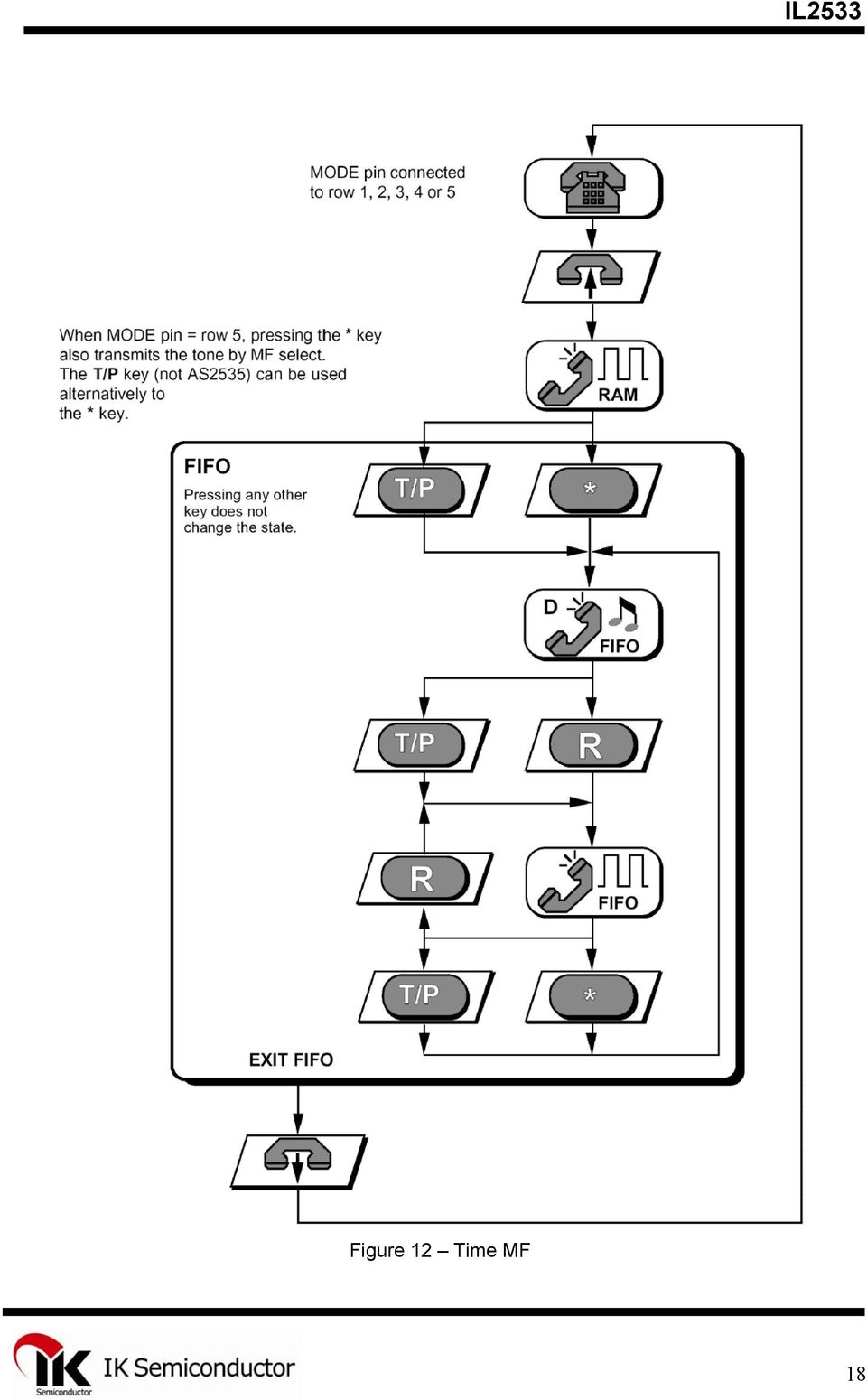
10 Z IN Z1 Z BAL Z2 Figure 8 Side Tone Balance DIALING FUNCTION DIGITAL KEYS Key scanning is allowed, when HS/DPN is set up as high and V DD is higher than V REF. A valid key is detected from the keyboard by connecting the appropriate row to the column (R ON < 1 ком). It can be done using keyboard matrix N x M with single contacts. Four diodes are used for lines quantity extension (see keyboard connecting at figure 3.). Also it is possible to connect microcontroller to lines and columns. P/M KEY Р/М key is used for entry into the program/no-signal state. Pressing Р/М key disconnects speech circuit and device is set to program state. Repetitive pressing of P/M key disconnects nosignal mode and program state (function with two states). When program/no-signal state is activated, light-emitting indication is connected (flash: 80ms ON and 1s OFF. ). SELECTING OF DIALING MODE Initial mode (LD or MF) can be chosen by output mode. LD is default selection, time transfer to invoke by pressing T/P key or MF mode can be invoke by pressing T/P key or " " key (when mode input = line 5, by first pressing of " " key, MF tone generating). Circuit will revert to initial LD state after pressing of T/P key or after pressing of R (R1, R2 or R3) key or after switch arm actuation. When MF mode is selected by output mode, circuit can not be switched to LD and will stay in MF mode. AUTOMATIC SET UP KEY Letter keys allow to use easily services of interconnections automatic setup. Keys А, В, С or D are available only in MF mode (including temporal MF) and are not saved. Pressing of one of these keys will invoke transferring of corresponding MF. Automatic set up keys are not saved to RAM, but sequentially entered signs are accumulated into FIFO buffer. Redialing of the last number (LNR) is a possibility, that allows to transfer repetitive last hand-dialed number, without pressing the same keys. LNR can be repeated after every receiver put up. Current RAM contents is overwritten by newly entered data. Hand-entered number is automatically save to LNR RAM. RAM storage capacity is 31 digit. If dialed number is larger than 31 digit, LNR possibility will be blocked (until new data will be less than 31 digit) and further entered data will be buffered to FIFO. By PS key pressing, pauses can be put out. 10

11 Digits, dialed later, i.e. digits entered by hand after LNR invocation, are not stored to RAM, but buffered to FIFO. REDIALING The last hand-dialed number can be redial without lever pressing, with the help of RP key. If dialed number is busy, than pressing of RP key interrupts line for 1.6 с (in order to pass to new dialing) and after pause number will be repeated. Redialing function is allowed, if number was dialed before pressing RP key. It can be called unlimited times till next pressing of the lever. During 1.6-second interval, device is in lower energy consumption mode for current saving. REPEATED CALL FUNCTION Repeated call activation (R1, R2 or R3 keys) will cause flash (with periodic intervals), at that R1 flashes are never accomplished in LD mode. R2 and R3 will be implemented independently of mode. If repeated call is repeated record in digit line, it will be stored into LNR RAM, when digit (digits) are entered after repeated call. If redial key is pressed after entering of digit line into FIFO buffer with sequentially entered digit. If redial key pressing does not accompanying by digits entering, LNR RAM stays untouched. After number redialing, pause with duration 270 ms will be accomplished. Keys from М1 to М12 are keys of direct memory access, and MR key is used for abbreviated dialing. Table 2 Memory structure Quantity of numbers or keys Number storing 14 Keys of direct memory access 4 Indirect memory 10 Numbers can be stored to on-chip RAM. Every number can contain upto 21 digit (including pauses). During programming several pauses can be entered by PS or LNR keys pressing. Every pause, inserted within first 5 entries will be automatically limited after 2 seconds, while pauses, inserted after position 5 in the digit line will stop dialing that can be continued after PS or LNR keys pressing. Stop function allows dialing in PABX extension. Example is stored in М1, where " " is pause/waiting, and 123 is extension number: 1) Lift up the receiver. Wait for tone signal; 2) Press М1 (45678 will be dialed); 3) Wait for tone signal from called РАВХ; 4) Press PS or LNR (123 will be dialed). Dialing from the memory is cascade. However, one memory cell contents shall be dialed before new one can be invoked. РАВХ PAX with outcoming and incoming communication. 11

12 FLOATING MARKER METHOD In order to accomplish simple LNR dialing after connection with Automatic telephone system Protocol of floating marker is used. If new entry coincides with contained in RAM, LNR key pressing will cause automatic dialing of rest digits. If there is inequality in coincidence, than LNR blocked till next lever pressing, and RAM will contain new number. Example (LNR contents, where 9 is access code): 1) Lift up the receiverснять, wait for Automatic telephone system dial tone; 2) press 9 and wait for outer dial tone; 3) Press LNR (12345 will be dialed). TONE OSCILLATOR Tone oscillator includes DTMF tones, three main frequencies for tone ring and quieting DTMF tones. DTMF oscillator provides 8 frequencies, namely: Lower Group: Sig А 697 Hz ns Sig ns В 770 Hz Sig ns Sig ns Hz С * # - D 941 Hz Upper Group Sig * 1209 Hz ns Sig Hz ns Sig # 1477 Hz ns Sig А В - С 1633 Hz ns D The output level of MF can be set by means of the external divider to the pin MFL. Voltage at Pin MFL (2) 1.50 В (A GND) -4.0 dbm 1.27 B -5.2 dbm 1.15 B -6.4 dbm 1.03 B -7.6 dbm 0.90 B -8.8 dbm 0.70 B dbm 0.54 B dbm 0.42 B dbm 0.30 B dbm 0.18 B dbm 0.00 B (V SS ) dbm DTMF Level (Lower Group) (Z LINE = 600 Оhm) The preliminary distortion constitutes 2.6 db. MF tones comply with the recommendations of CEPT. 12
: 1) Lift up the receiverснять, wait for Automatic telephone system dial tone; 2) press 9 and wait for outer dial tone; 3) Press LNR (12345 will be")
13 Tone Ring (MELODY / LOUDNESS) The three main parts for the melodies are as follows: F1 = 800 Hz, F2 = 1067 Hz and F3 = 1333 Hz (± 5 %). Frequency of repetition and loudness of the tone melody rings can be programmed by pressing Р/М and #, indicated with a sign in compliance with Table 4. Table 4 SIG N FREQUENCY OF REPETITION LOUDNESS 1 1 time (50 msec pause) -16 db 2 1 time (50 msec pause) - 7 db 3 1 time (50 msec pause) 0 db (max) 4 4 times -16 db 5 4 times - 7 db 6 4 times (by default) 0 db (max) 7 10 times -16 db 8 10 times - 7 db 9 10 times 0 db (max) 0 None OFF The procedure is completed by the repetitious pressing of the key Р/М. The default setting complies with the figure 6, i.e. after the supply ON preset the device will be started with the repetition rate of 4 and the maximum loudness. If the sign 0 is programmed, then the tone ring will be disabled until the next receiver lift, when it is set for the last preset value, previous to zero. The programmed preset values are stored in RAM on the chip. The repetition frequency signifies, that the sequence from 6 frequencies is repeated 1.4 or 10 times during 1 sec. The frequency sequence is controlled by means of the sequence register as follows: Sequence F1 F2 F3 F1 F2 F3... QUIETING TONE During the MF dialing the number the DIMF tones are applied to the phone speaker as a comforting tone. In the course of programming entry of the keys is indicated by means of the quieting tone of 1477 Hz. The quieting tone level constitutes approximately 60 mb at the output of RO. Duration constitutes 40 msec. After each key pressing in the program mode. When the program mode is terminated with the key Р/М, the identification tone is applied of 140 msec. An erroneous key pressing shall cause termination of the program mode, indicated by the denial tone 4 times of 40 msec with the pauses of 28 msec between the tone enablings. 13
 0 db (max) 7 10 times -16 db 8 10 times - 7 db 9 10 times 0 db (max) 0 None OFF The procedure is completed by the repetitious pressing of the key Р/М.")
14 IDENTIFICATION OF THE RING FREQUENCY The ring frequency identification block assumes, that only the signals with the frequencies between 13 and 70 Hz shall be considered as the real ringing signals. The real ringing signal identification time constitutes 1/f sec, where f is equal to the ring frequency. When the real ringing signal is continuously available during 73 msec, the melody generator is activated and remains active as long as the ring signal is available. As soon as the melody generator is started, the ring signal is continuously monitored, and the melody generator is enabled or disabled instantly in compliance with the short time availability of the correct or erroneous ring signal appropriately (until the next supply enabling or hanging up the recever). 하 Громкость Комфорт. тон SC - 0 db dB dB + RO 80 k 8 k Z LINE Z BAL (10 x Z LINE ) STB Z SYN (970 Ом) RI 300 Ом LI CS 30 Ом - 12dB + + Z REF DTMF Отключ. звука Компенсация потерь в линии - 23dB + 20 k 20 k M1 M2 CI 32.3 x Z REF Figure 9 Speech circuit model by the alternating current 14

15 LEGEND STATUSES INPUTS PROCESSING No operation (receiver put, no Receiver lift- Forced break (sec) Speech mode Receiver put- Number dialing (LD Cut-off from outsiders Key pressing Saving (storing in Programming Erroneous program entry Number entry Entry in compliance Processing in compliance Read-out from Incorrect entry Status compliance in with Figure 10 Symbols 15

16 16

17 Figure 11 Ring tone programming 17

18 Figure 12 Time MF 18
19 19

20 Figure 13 Storing numbers Complex impedance (270 Оhm Оhm // 150 nf) Figure 14 Automatic number dialing 20

21 Those components are included only, which are required for representing the complete functions of the microcircuits. The external components can be altered for compliance with the requirements of the various national standards and for matching the various converters. As a microcircuit is a component, but not a complete system, it cannot be applied as a separately positioned individual element on the standard basis. Consequently, the complete compliance with any standards depends upon application, where a microcircuit is used, and therefore selection of the standard application is the responsibility prerequisite of the Customer, and the manufacturer does not check the device for compliance with the concrete standards. 1 Line adaptation. Power selection. D. C. masking. 2 Line current read-out. 3 Soft limitation Мягкое ограничение of the automatic gain control. 4 Melody sequence setting block. 5 Ring frequency limitation. 6 Control logic. 7 Current generator. 8 Oscilloscope. 9 RAM. Melody. Automatic number dialer. 10 Keyboard. МЕТHOD OF OPERATION PRINCIPLES OF OPERATION Methods of the microcircuit potentialities application are optimized in such a way, so as: - to comply with the expectations of the user; - to be easy for training and upgradation; - not to cause any automatic functions, which are not expected by the user - to protect the user from making the critical errors, i.е. from dialing incorrect numbers, deletion of the stored numbers, etc.; - to be matching, simple and convenient in operation. Молчание Маскирование HS/DP t IDP t PDP t B t M t B t M t IDP t PDP t B t M Figure 15 Time chart of the number dialing 21
22 MUTE MASK HS/DPN t IDP t PDP t B t M t B t M t AP t IDP t PDP t B t M Figure 16 Time chart of the LD number dialing with the access pause MUTE MASK HS/DPN TONE t t IDP IDP t AP t IDP Figure 17 Time chart of the MF number dialing MUTE MASK HS/DPN t M t FD t M t PFP t M t FD t M Figure 18 Flashing time chart 22
23 Figure 19 Time chart of the number redialing Table 5 ELECTRIC CHARACTERISTICS ( V DD = (4.5 ± 0.5) V; I LINE = 15 ma; f = 800 Hz; Та = ( 25; +70) С, if otherwise not stated below) Description of Parameter, Unit of Measurement Parameter Letter Identification Mode Norm Not less Not more Remark Input voltage range, V, by inputs М1, М2 V Consumption current, mа I DD1 Speech mode 5 I DD2 MF dialing 1) 8.0 I DD3 LD dialing 2). V DD =2.5 V 400 I DD4 Ring mode. V DD =2.5 V 600 Storage current, mcа I DDO Standby mode. 0.1 V DD = 2 V; Ta = 25 C Low level output current, mа by output CS I OL(CS) V OL = 0.4 V 1.5 by output HS/DP I OL(HS/DP) 1.5 by output MO I OL(MO) 1.5 by output LED I OL(LED) 4.0 Line voltage (by preset default value), V V LI 13 mа I L 100 mа Transfer (T X ) Transfer gain coefficient, db A TX М1, М2 relative to LI Alteration of gain coefficient depending on A TX/F М1, М2 relative to LI frequency, db f = ( ) Hz Distortion coefficient, % THD 1 3) V LI 0.25V RMS 2 Soft limitation level, V V AGC1 Speech mode 4) 1.6V PEAK 2.4V PEAK Soft limitation overload, db A SCO Input signal rise time, mcsec/6db t ATTACK Input signal fall time, msec/6db t DECAY Input impedance, kоhm, Z IN By inputs М1, М2 Attenuation during silence, db A MUTE Silence mode 60 Output noise voltage, dbm V NO1 Та = 25 C - 72 Differential 0.75V PEAK 1.25V PEAK IN MAX1 Single-sided 0.375V PEAK 0.625V PEAK 23
24 Table 5 Continued Description of Parameter, Unit of Measurement Parameter Letter Identification Output Driver (BJT) Mode min Norm max Remark Input voltage range, V, by input LI V IN MAX2-2V PEAK 2V PEAK Dynamic range, V V TX 1.5V PEAK 2.5V PEAK Reflection attenuation, db RL Z RL = 1000 Оhm, 18 Та = 25 C Attenuation alteration from temperature, Z AC/ТЕМР Оhm/ С Reception (R X ) Reception gain coefficient (by default), db A RX0 LI relative to RO Loudness gain coefficient, db A VOL1 Key VOL Loudness gain coefficient, db A VOL2 (-/+) keys Alteration of the gain coefficient from the A RX/F f from 500 to 3400 Hz input frequency, db Distortion coefficient, % ТНD 2 Speech mode. 2 V RI 0.25 V RMS Soft limitation level, V V AGC2 Speech mode 0.8V PEAK 1.2V PEAK Soft limitation overload, db A SCO Speech mode 10 Input signal rise time, mcsec/6db t ATTACK V RI > 0.8 V RMS Input signal fall time, msec/6db t DECAY Noise output voltage, dbm 5) V NO2 Speech mode. -72 Та = 25 C Undesirable frequency components, dbm V UFC from 50 to 20 khz -60 Input impedance, kohm, by input RI Z IN RI Speech mode Input voltage range, V, by input RI V IN RI Speech mode 2V PEAK 2V PEAK Side tone suppresion, db A ST V RI 0.25 V RMS 26 Input voltage range, V, by input STB V INST Speech mode 2V PEAK 2V PEAK Input impedance, kohm, by input STB Z IN STB Speech mode DTMF 6) Mode Frequency deviation, % F MF tone level (lower group), db V MF1 MFL = A GND V MF2 MFL = V SS Fore-distortion from the low level to high V L-H level, db Undesirable frequency components, dbm V UFC1 f from 300 Hz to 5 khz MFL = V SS V UFC2 f from 5 to 14 khz -50 V UFC3 f from14 to 28.5 khz -70 V UFC4 f from 28.5 to 40 khz -80 Tone duration, msec t TD Mode: line 6 or , 4 Intertone pause, msec t ITP1 Mode:line t ITP2 Mode: line , 4 Tone rise time, msec t TR 5 5 Tone fall time, msec t TF Keyboard Wobble elimination time, msec td Input HS/DP Wobble elimination during transfer from low t HS-L Receiver lift-up status to high status, msec Wobble elimination during transfer from t HS-H1 No LD number dialing high status to low status, msec `LD mode Number dialing rate, pulse/sec t DR1 Mode: line 1, 2 or t DR2 Mode: line 3 or Pulse duration, msec t/b 1 Mode: line t/b 2 Mode: line t/b 3 Mode: line 1 or t/b 4 Mode: line
25 Table 5 Continued Description of Parameter, Unit of Measurement Parameter Letter Identification t HS-H2 In progress of LD number dialing Duration of interpulse pause, msec t M1 Mode: line t M2 Mode: line t M3 Mode: line 1 or t M4 Mode: line Fore-digit pause, msec t PDP LD dialing. Alternately buttons 2, are pressed Internal sign pause, msec t IDP Mode: line 1, 2, 3, 4 or Flash duration, msec t FD1 Key R t FD2 Key R t FD3 Key R Duration of entry pause, msec t AP Time of repeat line interruption, sec t RP LD dialing RP button pressing Tone Ring Melody output, V V MO Ring mode Melody delay, мс t MO 10 Ring frequency, Hz f f f Call signal detection time, msec t DT 150 Minimum detectable frequency, Hz f MIN Ring mode 13 Maximum detectable frequency, Hz f MAX 70 Quieting Tone. Program Mode Tone frequency, Hz f PT Programming mode, key entry Voltage level at output RO, mv V RT Programming mode Pulse duration while pressing a key, msec t RTD-E Key value entry 35 Confirmation pulse duration, msec t RTD-A Limited by the key Р/М Deviation pulse duration, msec t RTD-R Incorrect key entry in the program mode Light Diode Output LED enabling time, msec t LED-ON Programming mode 80 Interval, sec t LED-OFF 1 Comfort Tone (DIMF) Voltage level at output RO relative to the V CT -30 voltage level at input LS, db Mode min Norm max Remark Notes 1 It does not enable the frequency deviation of the ceramic resonator 2 Relative to the high group 3 Values are valid at the time of the automatic number dialing and have the minimum value at the time of the manual number dialing, i.е. the tones will last as long as the key is pressed 4 At the time of the temporary MF mode 5 Rise time is the time from reaching 10% of the final value till the tone amplitude gets 90% of its final value 6 Pauses, entered within the limits of the first 5 entries of the sign chain, shall be automatically limited after 2 sec. Pauses, entered after position 5, can be limited manually only by pressing the key PS or LNR 7 Incorrect entry of a key in the program mode shall cause the tone sequence with 4 packs of tones of 40 msec and the pauses between the packs of 28 msec and the forced exit from the program mode 1) MF dialing frequency number dialing 2) LD dialing pulse number dialing 3) V RMS functioning voltage of the sinusoidal signal 4) V PEAK peak (amplitude span) voltage of the sinusoidal signal 5) dbm voltage value, determined by formula 1 dbm = 20 lg V / V (4) where V voltage, V 6) DTMF dual frequency number dialing ( particular case of the frequency dialing) 25
26 Table 6 Limit Permissible and Limit Modes of Microcircuit Operation Description of Mode Parameter, Unit of Measurement Parameter Letter Identification Limit Mode Permissible Limit Mode Norm Norm min max min max Supply voltage, V V DD Low level input voltage, V V IL 0 0.3V DD V DD High level input voltage, V V IH 0.7V DD V DD 0.7V DD V DD +0.3 Input voltage by pin LS, В V I By pin LI, CS By pin STB, RI -2.0 V DD +0.3 By pin MO Input current, ma I I Frequency, MHz F Storage temperature, С T STG ,5 10 Output voltage of line (LS), V PEAK 2,0 1,5 1,0 0,5 Soft limitation VLS Current of line 20 ma Frequency 800Hz Distortion Distortion, % Output voltage (microphone inputs M1,M2), мv PEAK Figure 20 Soft limitation and distortion during transfer 26
27 N SUFFIX PLASTIC DIP (MS - 001AB) A Dimension, mm B Symbol MIN MAX A B C F L D F NOTES: 1. Dimensions A, B do not include mold flash or protrusions. Maximum mold flash or protrusions 0.25 mm (0.010) per side. G 0.25 (0.010) M T D N C -T- K SEATING PLANE M H J G H J 0 10 K L M N 0.38 D SUFFIX SOIC (MS - 059AD) Dimension, mm H -T A D G (0.010) M T C M B K Symbol MIN MAX A B C D F NOTES: J Dimensions A and B do not include mold flash or protrusion. K Maximum mold flash or protrusion 0.15 mm (0.006) per side M for A; for B 0.25 mm (0.010) per side. P P C SEATING PLANE J R x 45 F M G H R
TONE/PULSE DIALER WITH REDIAL
 INTRODUCTION The KS58006 is DTMF/PULSE switchable dialer with a 32-digit redial which can be done using a slide switch. All necessary dual-tone frequencies are derived from a 3.579545 MHz T crystal or
Programmable Single-/Dual-/Triple- Tone Gong SAE 800
 Programmable Single-/Dual-/Triple- Tone Gong Preliminary Data SAE 800 Bipolar IC Features Supply voltage range 2.8 V to 18 V Few external components (no electrolytic capacitor) 1 tone, 2 tones, 3 tones
HT1632C 32 8 &24 16 LED Driver
 328 &216 LED Driver Features Operating voltage: 2.V~5.5V Multiple LED display 32 ROW /8 COM and 2 ROW & 16 COM Integrated display RAM select 32 ROW & 8 COM for 6 display RAM, or select 2 ROW & 16 COM for
HT9170 DTMF Receiver. Features. General Description. Selection Table
 DTMF Receiver Features Operating voltage: 2.5V~5.5V Minimal external components No external filter is required Low standby current (on power down mode) General Description The HT9170 series are Dual Tone
Firmware version: 1.10 Issue: 7 AUTODIALER GD30.2. Instruction Manual
 Firmware version: 1.10 Issue: 7 AUTODIALER GD30.2 Instruction Manual Firmware version: 2.0.1 Issue: 0.6 Version of the GPRS transmitters configurator: 1.3.6.3 Date of issue: 07.03.2012 TABLE OF CONTENTS
Automatic Telephone Dialer TD-101(W)
") Automatic Telephone Dialer TD-101(W) The TD-101 is an automatic dialing device which can transmit prerecorded information via the telephone line. The dialer can send two different 10 second voice messages
Automatic Telephone Dialer TD-101(W) The TD-101 is an automatic dialing device which can transmit prerecorded information via the telephone line. The dialer can send two different 10 second voice messages
HM91710A/B TONE/PULSE TONE/PULES SWITCHABLE DIALER
 HM91710A/B /PULSE /PULES SWITCHABLE DIALER GENERAL DESCRIPTION The HM91710A/B are Tone/Pulse switchable dialer which are fabricated in CMOS technology with wide operating voltage for both tone and pulse
DS1307ZN. 64 x 8 Serial Real-Time Clock
 DS137 64 x 8 Serial Real-Time Clock www.maxim-ic.com FEATURES Real-time clock (RTC) counts seconds, minutes, hours, date of the month, month, day of the week, and year with leap-year compensation valid
Telecommunications Switching Systems (TC-485) PRACTICAL WORKBOOK FOR ACADEMIC SESSION 2011 TELECOMMUNICATIONS SWITCHING SYSTEMS (TC-485) FOR BE (TC)
 PRACTICAL WORKBOOK FOR ACADEMIC SESSION 2011 TELECOMMUNICATIONS SWITCHING SYSTEMS (TC-485) FOR BE (TC)") PRACTICAL WORKBOOK FOR ACADEMIC SESSION 2011 TELECOMMUNICATIONS SWITCHING SYSTEMS (TC-485) FOR BE (TC) Department of Electronic Engineering NED University of Engineering and Technology, Karachi LABORATORY
PRACTICAL WORKBOOK FOR ACADEMIC SESSION 2011 TELECOMMUNICATIONS SWITCHING SYSTEMS (TC-485) FOR BE (TC) Department of Electronic Engineering NED University of Engineering and Technology, Karachi LABORATORY
LC898300XA. Functions Automatic adjustment to the individual resonance frequency Automatic brake function Initial drive frequency adjustment function
 Ordering number : A2053 CMOS LSI Linear Vibrator Driver IC http://onsemi.com Overview is a Linear Vibrator Driver IC for a haptics and a vibrator installed in mobile equipments. The best feature is it
DATA SHEET. TDA8560Q 2 40 W/2 Ω stereo BTL car radio power amplifier with diagnostic facility INTEGRATED CIRCUITS. 1996 Jan 08
 INTEGRATED CIRCUITS DATA SHEET power amplifier with diagnostic facility Supersedes data of March 1994 File under Integrated Circuits, IC01 1996 Jan 08 FEATURES Requires very few external components High
FEATURES DESCRIPTION APPLICATIONS BLOCK DIAGRAM. PT2248 Infrared Remote Control Transmitter
 Infrared Remote Control Transmitter DESCRIPTION PT2248 is an infrared remote control transmitter utilizing CMOS Technology. It is capable of 18 functions and a total of 75 commands. Single-shot and continuous
DATA SHEET. TDA1518BQ 24 W BTL or 2 x 12 watt stereo car radio power amplifier INTEGRATED CIRCUITS
 INTEGRATED CIRCUITS DATA SHEET File under Integrated Circuits, IC01 July 1994 GENERAL DESCRIPTION The is an integrated class-b output amplifier in a 13-lead single-in-line (SIL) plastic power package.
NTE2053 Integrated Circuit 8 Bit MPU Compatible A/D Converter
 NTE2053 Integrated Circuit 8 Bit MPU Compatible A/D Converter Description: The NTE2053 is a CMOS 8 bit successive approximation Analog to Digital converter in a 20 Lead DIP type package which uses a differential
DS1621 Digital Thermometer and Thermostat
 Digital Thermometer and Thermostat www.dalsemi.com FEATURES Temperature measurements require no external components Measures temperatures from 55 C to +125 C in 0.5 C increments. Fahrenheit equivalent
MH88500. Hybrid Subscriber Line Interface Circuit (SLIC) Preliminary Information. Features. Description. Applications. Ordering Information
 Preliminary Information. Features. Description. Applications. Ordering Information") Hybrid Subscriber Line Interface Circuit (SLIC) Features Differential to single ended conversion No transformers required Minimum installation space Off-Hook detection and LED indicator drive Relay drive
Hybrid Subscriber Line Interface Circuit (SLIC) Features Differential to single ended conversion No transformers required Minimum installation space Off-Hook detection and LED indicator drive Relay drive
Supply voltage Supervisor TL77xx Series. Author: Eilhard Haseloff
 Supply voltage Supervisor TL77xx Series Author: Eilhard Haseloff Literature Number: SLVAE04 March 1997 i IMPORTANT NOTICE Texas Instruments (TI) reserves the right to make changes to its products or to
AUTODIALLER / QUICKDIALLER - SA132
 AUTODIALLER / QUICKDIALLER - SA132 INSTRUCTION LEAFLET ENGLISH www.thermomax-group.com CONTENTS 1 SETUP AT A GLANCE... 2 2 FOREWORD....... 3 3 INSTALLATION...... 4 4 KEYPAD AND INDICATORS...... 5 SETTING
Manufactures of: All. Dallas Delta Corporation Pty.Ltd. Pty.Ltd. 102 Albert St. East Brunswick, 3057 Vic. Tel: 613 93877388 Fax: 613 93873128
 Dallas Delta Corporation Pty.Ltd. 102 Albert St. East Brunswick, 3057 Vic. Tel: 613 93877388 Fax: 613 93873128 Email: sales@dallasdelta.com.au www.dallasdelta.com.au LP GUARD DOORSTATION MK II G UARD Doorstation
APPLICATION NOTE # Using Sage SMOS for VoIP Testing, IP Phone to IP Phone TABLE OF CONTENTS
 Product: 930A L3 Communications Test Set 935AT Communications Test Set APPLICATION NOTE # Using Sage SMOS for VoIP Testing, IP Phone to IP Phone TABLE OF CONTENTS Introduction... 2 Configuring 935AT #1
Kit 27. 1W TDA7052 POWER AMPLIFIER
 Kit 27. 1W TDA7052 POWER AMPLIFIER This is a 1 watt mono amplifier Kit module using the TDA7052 from Philips. (Note, no suffix.) It is designed to be used as a building block in other projects where a
SG2525A SG3525A REGULATING PULSE WIDTH MODULATORS
 SG2525A SG3525A REGULATING PULSE WIDTH MODULATORS 8 TO 35 V OPERATION 5.1 V REFERENCE TRIMMED TO ± 1 % 100 Hz TO 500 KHz OSCILLATOR RANGE SEPARATE OSCILLATOR SYNC TERMINAL ADJUSTABLE DEADTIME CONTROL INTERNAL
100V - 100W DMOS AUDIO AMPLIFIER WITH MUTE/ST-BY THERMAL SHUTDOWN STBY-GND
 TDA7294 100V - 100W DMOS AUDIO AMPLIFIER WITH MUTE/ST-BY VERY HIGH OPERATING VOLTAGE RANGE (±40V) DMOS POWER STAGE HIGH OUTPUT POWER (UP TO 100W MU- SIC POWER) MUTING/STAND-BY FUNCTIONS NO SWITCH ON/OFF
Tire pressure monitoring
 Application Note AN601 Tire pressure monitoring 1 Purpose This document is intended to give hints on how to use the Intersema pressure sensors in a low cost tire pressure monitoring system (TPMS). 2 Introduction
LOGIC DIAGRAM PIN ASSIGNMENT
 TECNICAL DATA Tone Ringer IL2411N/D The IL2411 is a bipolar integrated circuit designed for telephone bell replacement. Designed for Telephone Bell Replacement Low Current Drain Adjustable 2-frequency
Glolab Talking Phone Dial Monitor
 Introduction The detects the tones generated when numbers are dialed on your touch tone telephone and speaks the numbers that were dialed. This verifies that you dialed the correct number and is especially
1. Learn about the 555 timer integrated circuit and applications 2. Apply the 555 timer to build an infrared (IR) transmitter and receiver
 transmitter and receiver") Electronics Exercise 2: The 555 Timer and its Applications Mechatronics Instructional Laboratory Woodruff School of Mechanical Engineering Georgia Institute of Technology Lab Director: I. Charles Ume,
Electronics Exercise 2: The 555 Timer and its Applications Mechatronics Instructional Laboratory Woodruff School of Mechanical Engineering Georgia Institute of Technology Lab Director: I. Charles Ume,
LM138 LM338 5-Amp Adjustable Regulators
 LM138 LM338 5-Amp Adjustable Regulators General Description The LM138 series of adjustable 3-terminal positive voltage regulators is capable of supplying in excess of 5A over a 1 2V to 32V output range
SPREAD SPECTRUM CLOCK GENERATOR. Features
 DATASHEET ICS7152 Description The ICS7152-01, -02, -11, and -12 are clock generators for EMI (Electro Magnetic Interference) reduction (see below for frequency ranges and multiplier ratios). Spectral peaks
FX604. CML Semiconductor Products. V23 Compatible Modem. 1.0 Features. 1200/75 bits/sec Full Duplex V23 compatible Modem with:
 CML Semiconductor Products V23 Compatible Modem FX604 1.0 Features D/604/3 November 1996 Provisional Information 1200/75 bits/sec Full Duplex V23 compatible Modem with: Optional 75bits/sec Back Channel
Miniature Surface-Mount DAA for Audio or Data Transfer XE0402LCC BLOCK DIAGRAM
 XE0402LCC January 2007 Miniature Surface-Mount DAA for Audio or Data Transfer Description The XE0402LCC supplies a complete telephone line interface or DAA (Data Access Arrangement) in a miniature, surface-mount
.OPERATING SUPPLY VOLTAGE UP TO 46 V
 L298 DUAL FULL-BRIDGE DRIVER.OPERATING SUPPLY VOLTAGE UP TO 46 V TOTAL DC CURRENT UP TO 4 A. LOW SATURATION VOLTAGE OVERTEMPERATURE PROTECTION LOGICAL "0" INPUT VOLTAGE UP TO 1.5 V (HIGH NOISE IMMUNITY)
Data Acquisition Module with I2C interface «I2C-FLEXEL» User s Guide
 Data Acquisition Module with I2C interface «I2C-FLEXEL» User s Guide Sensors LCD Real Time Clock/ Calendar DC Motors Buzzer LED dimming Relay control I2C-FLEXEL PS2 Keyboards Servo Motors IR Remote Control
NTE923 & NTE923D Integrated Circuit Precision Voltage Regulator
 NTE923 & NTE923D Integrated Circuit Precision Voltage Regulator Description: The NTE923 and NTE923D are voltage regulators designed primarily for series regulator applications. By themselves, these devices
Voice Dialer Speech Recognition Dialing IC
 Speech Recognition Dialing IC Speaker Dependent IC for Voice Dialing Applications GENERAL DESCRIPTION The IC, from the Interactive Speech family of products, is an application specific standard product
1ED Compact A new high performance, cost efficient, high voltage gate driver IC family
 1ED Compact A new high performance, cost efficient, high voltage gate driver IC family Heiko Rettinger, Infineon Technologies AG, Am Campeon 1-12, 85579 Neubiberg, Germany, heiko.rettinger@infineon.com
INTEGRATED CIRCUITS DATA SHEET. TDA7000 FM radio circuit. Product specification File under Integrated Circuits, IC01
 INTEGRATED CIRCUITS DATA SHEET File under Integrated Circuits, IC01 May 1992 GENERAL DESCRIPTION The is a monolithic integrated circuit for mono FM portable radios, where a minimum on peripheral components
DS2187 Receive Line Interface
 Receive Line Interface www.dalsemi.com FEATURES Line interface for T1 (1.544 MHz) and CEPT (2.048 MHz) primary rate networks Extracts clock and data from twisted pair or coax Meets requirements of PUB
HD61202U. (Dot Matrix Liquid Crystal GraphicDisplay Column Driver)
") HD622U (Dot Matrix Liquid Crystal GraphicDisplay Column Driver) Description HD622U is a column (segment) driver for dot matrix liquid crystal graphic display systems. It stores the display data transferred
HD622U (Dot Matrix Liquid Crystal GraphicDisplay Column Driver) Description HD622U is a column (segment) driver for dot matrix liquid crystal graphic display systems. It stores the display data transferred
BATRON DOCUMENT NUMBER AND REVISION VL-FS-BTHQ 21605VSS-02 REV.A (BTHQ 21605VSS-FSTF-LED05W(1 DIE)) Feb/2002 BTHQ 21605-FSTF-LED WHITE 1/15
) Feb/2002 BTHQ 21605-FSTF-LED WHITE 1/15") Feb/2002 1/15 DOCUMENT NUMBER AND REVISION VL-FS-BTHQ 21605VSS-02 REV.A (BTHQ 21605VSS-FSTF-LED05W(1 DIE)) 2/15 DOCUMENT REVISION HISTORY 1: DOCUMENT REVISION DATE DESCRIPTION CHANGED BY FROM TO A 2002.01.09
Feb/2002 1/15 DOCUMENT NUMBER AND REVISION VL-FS-BTHQ 21605VSS-02 REV.A (BTHQ 21605VSS-FSTF-LED05W(1 DIE)) 2/15 DOCUMENT REVISION HISTORY 1: DOCUMENT REVISION DATE DESCRIPTION CHANGED BY FROM TO A 2002.01.09
ICS379. Quad PLL with VCXO Quick Turn Clock. Description. Features. Block Diagram
 Quad PLL with VCXO Quick Turn Clock Description The ICS379 QTClock TM generates up to 9 high quality, high frequency clock outputs including a reference from a low frequency pullable crystal. It is designed
PS 29M DUAL CHANNEL BELTPACK IN METAL CASE
 PS 29M DUAL CHANNEL BELTPACK IN METAL CASE USER MANUAL October 2013 This product is designed and manufactured by: ASL Intercom BV Zonnebaan 42 3542 EG Utrecht The Netherlands Phone: +31 (0)30 2411901 Fax:
1 All safety instructions, warnings and operating instructions must be read first.
 ONYX USER MANUAL 2 Dateq ONYX Manual Safety instructions EN Safety instructions 1 All safety instructions, warnings and operating instructions must be read first. 2 All warnings on the equipment must be
Kit 106. 50 Watt Audio Amplifier
 Kit 106 50 Watt Audio Amplifier T his kit is based on an amazing IC amplifier module from ST Electronics, the TDA7294 It is intended for use as a high quality audio class AB amplifier in hi-fi applications
UNISONIC TECHNOLOGIES CO., LTD
 UPS61 UNISONIC TECHNOLOGIES CO., LTD HIGH PERFORMANCE CURRENT MODE POWER SWITCH DESCRIPTION The UTC UPS61 is designed to provide several special enhancements to satisfy the needs, for example, Power-Saving
Radiowe zdalne sterowanie
 Radiowe zdalne sterowanie 2 12 Series of Decoders Features Operating voltage: 2.4V~12V Low power and high noise immunity CMOS technology Low stand-by current Capable of decoding 12 bits of information
EMERGING DISPLAY CUSTOMER ACCEPTANCE SPECIFICATIONS 16400(LED TYPES) EXAMINED BY : FILE NO. CAS-10068 ISSUE : JAN.19,2000 TOTAL PAGE : 7 APPROVED BY:
 EXAMINED BY : FILE NO. CAS-10068 ISSUE : JAN.19,2000 TOTAL PAGE : 7 APPROVED BY:") EXAMINED BY : FILE NO. CAS-10068 APPROVED BY: EMERGING DISPLAY TECHNOLOGIES CORPORATION ISSUE : JAN.19,2000 TOTAL PAGE : 7 VERSION : 3 CUSTOMER ACCEPTANCE SPECIFICATIONS MODEL NO. : 16400(LED TYPES) FOR
EXAMINED BY : FILE NO. CAS-10068 APPROVED BY: EMERGING DISPLAY TECHNOLOGIES CORPORATION ISSUE : JAN.19,2000 TOTAL PAGE : 7 VERSION : 3 CUSTOMER ACCEPTANCE SPECIFICATIONS MODEL NO. : 16400(LED TYPES) FOR
PS323. Precision, Single-Supply SPST Analog Switch. Features. Description. Block Diagram, Pin Configuration, and Truth Table. Applications PS323 PS323
 Features ÎÎLow On-Resistance (33-ohm typ.) Minimizes Distortion and Error Voltages ÎÎLow Glitching Reduces Step Errors in Sample-and-Holds. Charge Injection, 2pC typ. ÎÎSingle-Supply Operation (+2.5V to
Features. Modulation Frequency (khz) VDD. PLL Clock Synthesizer with Spread Spectrum Circuitry GND
 VDD. PLL Clock Synthesizer with Spread Spectrum Circuitry GND") DATASHEET IDT5P50901/2/3/4 Description The IDT5P50901/2/3/4 is a family of 1.8V low power, spread spectrum clock generators capable of reducing EMI radiation from an input clock. Spread spectrum technique
DATASHEET IDT5P50901/2/3/4 Description The IDT5P50901/2/3/4 is a family of 1.8V low power, spread spectrum clock generators capable of reducing EMI radiation from an input clock. Spread spectrum technique
EMERGING DISPLAY CUSTOMER ACCEPTANCE SPECIFICATIONS 20400 (LED TYPES) EXAMINED BY : FILE NO. CAS-10184 ISSUE : DEC.01,1999 TOTAL PAGE : 7 APPROVED BY:
 EXAMINED BY : FILE NO. CAS-10184 ISSUE : DEC.01,1999 TOTAL PAGE : 7 APPROVED BY:") EXAMINED BY : FILE NO. CAS-10184 APPROVED BY: EMERGING DISPLAY TECHNOLOGIES CORPORATION ISSUE : DEC.01,1999 TOTAL PAGE : 7 VERSION : 2 CUSTOMER ACCEPTANCE SPECIFICATIONS MODEL NO. : 20400 (LED TYPES) FOR
EXAMINED BY : FILE NO. CAS-10184 APPROVED BY: EMERGING DISPLAY TECHNOLOGIES CORPORATION ISSUE : DEC.01,1999 TOTAL PAGE : 7 VERSION : 2 CUSTOMER ACCEPTANCE SPECIFICATIONS MODEL NO. : 20400 (LED TYPES) FOR
1.5A Very L.D.O Voltage Regulator LM29150/29151/29152
 FEATURES High Current Capability 1.5A Low Dropout Voltage 350mV Low Ground Current Accurate 1% Guaranteed Initial Tolerance Extremely Fast Transient Response Reverse-Battery and "Load Dump" Protection
Implementing a Digital Answering Machine with a High-Speed 8-Bit Microcontroller
 Implementing a Digital Answering Machine with a High-Speed 8-Bit Microcontroller Zafar Ullah Senior Application Engineer Scenix Semiconductor Inc. Leo Petropoulos Application Manager Invox TEchnology 1.0
X9C102/103/104/503. Terminal Voltages ±5V, 100 Taps. Digitally-Controlled (XDCP) Potentiometer
 Potentiometer") APPLICATION NOTE A V A I L A B L E AN20 AN42 53 AN71 AN73 AN88 AN91 92 AN115 Terminal Voltages ±5V, 100 Taps X9C102/103/104/503 Digitally-Controlled (XDCP) Potentiometer FEATURES Solid-State Potentiometer
APPLICATION NOTE A V A I L A B L E AN20 AN42 53 AN71 AN73 AN88 AN91 92 AN115 Terminal Voltages ±5V, 100 Taps X9C102/103/104/503 Digitally-Controlled (XDCP) Potentiometer FEATURES Solid-State Potentiometer
Spread Spectrum Clock Generator
 Spread Spectrum Clock Generator DESCRIPTION is a clock generator for EMI (Electro Magnetic Interference) reduction. The peak of unnecessary (EMI) can be attenuated by making the oscillation frequency slightly
WS2811. Signal line 256 Gray level 3 channal Constant current LED drive IC. http://www.world-semi.com. Feature. Applications. General description
 Feature Output port compression 12V. uilt in stabilivolt, Only add a resistance to IC VDD feet when under 24V power supply. ray level 256 can be adjusted and scan freque ncy not less than 400Hz/s. uilt
ISDN 970 Telephone USER MANUAL. Copyright 1999 Lucent Technologies Inc. All rights reserved. Printed in Mexico. Issue L3 847937794
 ISDN 970 Telephone USER MANUAL Copyright 1999 Lucent Technologies Inc. All rights reserved. Printed in Mexico. Issue L3 847937794 Table of Contents ABOUT ISDN... 3 ISDN TERMS... 3 A GUIDE TO THIS MANUAL...
)454 6. SERIES V: DATA COMMUNICATION OVER THE TELEPHONE NETWORK Interfaces and voiceband modems. ITU-T Recommendation V.25
454 6. SERIES V: DATA COMMUNICATION OVER THE TELEPHONE NETWORK Interfaces and voiceband modems. ITU-T Recommendation V.25") INTERNATIONAL TELECOMMUNICATION UNION )454 6 TELECOMMUNICATION STANDARDIZATION SECTOR OF ITU (10/96) SERIES V: DATA COMMUNICATION OVER THE TELEPHONE NETWORK Interfaces and voiceband modems!utomatic ANSWERING
INTERNATIONAL TELECOMMUNICATION UNION )454 6 TELECOMMUNICATION STANDARDIZATION SECTOR OF ITU (10/96) SERIES V: DATA COMMUNICATION OVER THE TELEPHONE NETWORK Interfaces and voiceband modems!utomatic ANSWERING
Security Auto Dialer. Owner s Manual. Please read before using this equipment.
 Security Auto Dialer Owner s Manual Please read before using this equipment. ˆ Contents Features... 2 FCC Statement... 3 Lightning... 3 A Quick Look at Your Auto Dialer... 4 Installation... 5 Selecting
AppNote 404 EM MICROELECTRONIC - MARIN SA. EM4095 Application Note RFID. Title: Product Family: TABLE OF CONTENT. Application Note 404
 EM MICROELECTRONIC - MARIN SA AppNote 0 Title: Product Family: Application Note 0 EM095 Application Note RFID Part Number: EM095 Keywords: RFID Transceiver, Reader Chip, EM095 Date: 5 September 00 TABLE
Connect to telephone. Connect to wall jack
 AD350-SE Multi-Function Auto Dialer Installation Install the AD350 SE Multi Function Auto Dialer as shown in the below diagram. The AD350 SE is only work on standard analog phones. Do not install the dialer
TL084 TL084A - TL084B
 A B GENERAL PURPOSE JFET QUAD OPERATIONAL AMPLIFIERS WIDE COMMONMODE (UP TO V + CC ) AND DIFFERENTIAL VOLTAGE RANGE LOW INPUT BIAS AND OFFSET CURRENT OUTPUT SHORTCIRCUIT PROTECTION HIGH INPUT IMPEDANCE
DS2186. Transmit Line Interface FEATURES PIN ASSIGNMENT
 DS2186 Transmit Line Interface FEATURES Line interface for T1 (1.544 MHz) and CEPT (2.048 MHz) primary rate networks PIN ASSIGNMENT TAIS 1 20 LCLK On chip transmit LBO (line build out) and line drivers
DS1621 Digital Thermometer and Thermostat
 www.maxim-ic.com FEATURES Temperature measurements require no external components Measures temperatures from -55 C to +125 C in 0.5 C increments. Fahrenheit equivalent is -67 F to 257 F in 0.9 F increments
CelluLine CGW-TS GSM Cellular Gateway. Installation and Programming Manual
 CelluLine CGW-TS GSM Cellular Gateway Installation and Programming Manual CelluLine CGW-TS GSM Cellular Gateway Installation and Programming Manual CGWTS-M001A Version 1, Release 1, December 2004 NOTICE
ICS514 LOCO PLL CLOCK GENERATOR. Description. Features. Block Diagram DATASHEET
 DATASHEET ICS514 Description The ICS514 LOCO TM is the most cost effective way to generate a high-quality, high-frequency clock output from a 14.31818 MHz crystal or clock input. The name LOCO stands for
2-Wire/4-Wire Telephone Line Interface. XE0204 Block Diagram
 XE0204 July 2000 2-Wire/4-Wire Telephone Line Interface Description The XE0204 provides a common telephone interface for networks integrating two and four-wire telephone connections. The XE0204 supplies
PACKAGE OUTLINE DALLAS DS2434 DS2434 GND. PR 35 PACKAGE See Mech. Drawings Section
 PRELIMINARY DS2434 Battery Identification Chip FEATURES Provides unique ID number to battery packs PACKAGE OUTLINE Eliminates thermistors by sensing battery temperature on chip DALLAS DS2434 1 2 3 256
TRIPLE PLL FIELD PROG. SPREAD SPECTRUM CLOCK SYNTHESIZER. Features
 DATASHEET ICS280 Description The ICS280 field programmable spread spectrum clock synthesizer generates up to four high-quality, high-frequency clock outputs including multiple reference clocks from a low-frequency
DATA SHEET. TDA1510AQ 24 W BTL or 2 x 12 W stereo car radio power amplifier INTEGRATED CIRCUITS
 INTEGRATED CIRCUITS DATA SHEET 24 W BTL or 2 x 12 W stereo car radio File under Integrated Circuits, IC01 January 1992 GENERAL DESCRIPTION The is a class-b integrated output amplifier encapsulated in a
PCAN-MicroMod Universal I/O Module with CAN Interface. User Manual. Document version 2.1.0 (2014-01-16)
") PCAN-MicroMod Universal I/O Module with CAN Interface User Manual Document version 2.1.0 (2014-01-16) Products taken into account Product Name Part number Model PCAN-MicroMod IPEH-002080 with firmware
PCAN-MicroMod Universal I/O Module with CAN Interface User Manual Document version 2.1.0 (2014-01-16) Products taken into account Product Name Part number Model PCAN-MicroMod IPEH-002080 with firmware
LDS8720. 184 WLED Matrix Driver with Boost Converter FEATURES APPLICATION DESCRIPTION TYPICAL APPLICATION CIRCUIT
 184 WLED Matrix Driver with Boost Converter FEATURES High efficiency boost converter with the input voltage range from 2.7 to 5.5 V No external Schottky Required (Internal synchronous rectifier) 250 mv
500r+ Installation and User Guide
 500r+ Installation and User Guide Compatible Equipment 502rUK-50 Watch/Pendant PA. 509rUK-50 Smoke Detector 515rUK-00 10 metre passive infra red movement detector. 525rUK-00 Remote Set/Unset (Full and
LSI/CSI LS7362 BRUSHLESS DC MOTOR COMMUTATOR/CONTROLLER DESCRIPTION:
 LSI/CSI LS UL LSI Computer Systems, Inc. 1 Walt Whitman oad, Melville, NY 11 (1) 1-000 FAX (1) 1-00 A00 BUSHLESS DC MOTO COMMUTATO/CONTOLLE FEATUES: Speed Control by Pulse Width Modulating (PWM) only the
DATA SHEET. TDA1543 Dual 16-bit DAC (economy version) (I 2 S input format) INTEGRATED CIRCUITS
 (I 2 S input format) INTEGRATED CIRCUITS") INTEGRATED CIRCUITS DATA SHEET File under Integrated Circuits, IC01 February 1991 FEATURES Low distortion 16-bit dynamic range 4 oversampling possible Single 5 V power supply No external components required
INTEGRATED CIRCUITS DATA SHEET File under Integrated Circuits, IC01 February 1991 FEATURES Low distortion 16-bit dynamic range 4 oversampling possible Single 5 V power supply No external components required
PI5A100. Precision, Wide-Bandwidth Quad SPDT Analog Switch. Description. Features. Block Diagram, Pin Configuration. Applications.
 Precision, Wide-Bandwidth Quad SPDT Analog Switch Features Single Supply Operation (+2V to +6V) Rail-to-Rail Analog Signal Dynamic Range Low On-Resistance (6Ω typ with 5V supply) Minimizes Distortion and
Technical Description. Multifunctional Desk-Top Call Station Digital Version 8, 16 Keys L.No. 1 760 4, 1 761 5
 Technical Description Multifunctional Desk-Top Call Station Digital Version 8, 16 Keys L.No. 1 760 4, 1 761 5 Contents 1. General remarks 2. Design 3. Block diagram 4. Function 4.1 Controller system with
ICS650-44 SPREAD SPECTRUM CLOCK SYNTHESIZER. Description. Features. Block Diagram DATASHEET
 DATASHEET ICS650-44 Description The ICS650-44 is a spread spectrum clock synthesizer intended for video projector and digital TV applications. It generates three copies of an EMI optimized 50 MHz clock
Emergency Dialer DIAL-ALERT. English MODEL : AD-433S. www.skylinkhome.com
 www.skylinkhome.com Emergency Dialer English DIAL-ALERT TM MODEL : AD-433S 101A320 JUNE, 2004 CUSTOMER SERVICE 17 Sheard Avenue, Brampton, Ontario, Canada L6Y 1J3 Tel : (800) 304-1187 Fax : (800) 286-1320
PECL and LVDS Low Phase Noise VCXO (for 65-130MHz Fund Xtal) XIN XOUT N/C N/C CTRL VCON (0,0) OESEL (Pad #25) 1 (default)
 XIN XOUT N/C N/C CTRL VCON (0,0) OESEL (Pad #25) 1 (default)") Reserved BUF BUF 62 mil OESEL^ Reserved Reserved PL520-30 FEATURES 65MHz to 130MHz Fundamental Mode Crystals. Output range (no PLL): 65MHz 130MHz (3.3V). 65MHz 105MHz (2.5V). Low Injection Power for crystal
Reserved BUF BUF 62 mil OESEL^ Reserved Reserved PL520-30 FEATURES 65MHz to 130MHz Fundamental Mode Crystals. Output range (no PLL): 65MHz 130MHz (3.3V). 65MHz 105MHz (2.5V). Low Injection Power for crystal
Series AMLDL-Z Up to 1000mA LED Driver
 FEATURES: Click on Series name for product info on aimtec.com Series Up to ma LED Driver Models Single output Model Input Voltage (V) Step Down DC/DC LED driver Operating Temperature range 4ºC to 85ºC
1 TO 4 CLOCK BUFFER ICS551. Description. Features. Block Diagram DATASHEET
 DATASHEET 1 TO 4 CLOCK BUFFER ICS551 Description The ICS551 is a low cost, high-speed single input to four output clock buffer. Part of IDT s ClockBlocks TM family, this is our lowest cost, small clock
TDA4605 CONTROL CIRCUIT FOR SWITCH MODE POWER SUPPLIES USING MOS TRANSISTORS
 CONTROL CIRCUIT FOR SWITCH MODE POWER SUPPLIES USING MOS TRANSISTORS Fold-Back Characteristic provides Overload Protection for External Diodes Burst Operation under Short-Circuit and no Load Conditions
LM79XX Series 3-Terminal Negative Regulators
 LM79XX Series 3-Terminal Negative Regulators General Description The LM79XX series of 3-terminal regulators is available with fixed output voltages of b5v b8v b12v and b15v These devices need only one
Impedance 50 (75 connectors via adapters)
") VECTOR NETWORK ANALYZER PLANAR TR1300/1 DATA SHEET Frequency range: 300 khz to 1.3 GHz Measured parameters: S11, S21 Dynamic range of transmission measurement magnitude: 130 db Measurement time per point:
VECTOR NETWORK ANALYZER PLANAR TR1300/1 DATA SHEET Frequency range: 300 khz to 1.3 GHz Measured parameters: S11, S21 Dynamic range of transmission measurement magnitude: 130 db Measurement time per point:
LOW POWER FM TRANSMITTER SYSTEM
 Order this document by MC28/D MC28 is a onechip FM transmitter subsystem designed for cordless telephone and FM communication equipment. It includes a microphone amplifier, voltage controlled oscillator
unit:mm 3022A-DIP12F 0.5 0.81 2.54
 Ordering number:enn1718b Monolithic Linear IC LA4550 2-Channel AF Power Amplifier for Radio, Tape Recorder Use Features Low quiescent current. On-chip 2 channels permitting use in stereo and bridge amplifier
TSL250, TSL251, TLS252 LIGHT-TO-VOLTAGE OPTICAL SENSORS
 TSL50, TSL5, TLS5 SOES004C AUGUST 99 REVISED NOVEMBER 995 Monolithic Silicon IC Containing Photodiode, Operational Amplifier, and Feedback Components Converts Light Intensity to Output Voltage High Irradiance
DS1721 2-Wire Digital Thermometer and Thermostat
 www.dalsemi.com FEATURES Temperature measurements require no external components with ±1 C accuracy Measures temperatures from -55 C to +125 C; Fahrenheit equivalent is -67 F to +257 F Temperature resolution
DRM compatible RF Tuner Unit DRT1
 FEATURES DRM compatible RF Tuner Unit DRT1 High- Performance RF Tuner Frequency Range: 10 KHz to 30 MHz Input ICP3: +13,5dBm, typ. Noise Figure @ full gain: 14dB, typ. Receiver Factor: -0,5dB, typ. Input
Hardware Documentation. Data Sheet HAL 202. Hall-Effect Sensor. Edition Sept. 18, 2014 DSH000159_002EN
 Hardware Documentation Data Sheet HAL 202 Hall-Effect Sensor Edition Sept. 18, 2014 DSH000159_002EN HAL202 Copyright, Warranty, and Limitation of Liability The information and data contained in this document
CAT28C64B F R E E. 64K-Bit CMOS PARALLEL EEPROM L E A D FEATURES DESCRIPTION BLOCK DIAGRAM
 64K-Bit CMOS PARALLEL EEPROM FEATURES Fast read access times: 90/120/150ns Low power CMOS dissipation: Active: 25 ma max. Standby: 100 µa max. Simple write operation: On-chip address and data latches Self-timed
DS12885, DS12885Q, DS12885T. Real Time Clock FEATURES PIN ASSIGNMENT
 DS12885, DS12885Q, DS12885T Real Time Clock FEATURES Drop in replacement for IBM AT computer clock/calendar Pin configuration closely matches MC146818B and DS1285 Counts seconds, minutes, hours, days,
MP2259 1A, 16V, 1.4MHz Step-Down Converter
 MP59 1A, 1V, 1.MHz Step-Down Converter TM The Future of Analog IC Technology DESCRIPTION The MP59 is a monolithic integrated stepdown switch mode converter with an internal power MOSFET. It achieves 1A
WEA-Base. User manual for load cell transmitters. UK WEA-Base User manual for load cell transmitters Version 3.2 UK
 WEA-Base User manual for load cell transmitters 1 Contents 1. Technical data... 3 2. Assembly... 4 2.1 Power supply... 4 2.2 Load cells... 4 2.3 RS-485... 4 2.4 Relays... 5 2.5 Digital input... 5 2.6 Analogue
IrDA Transceiver with Encoder/Decoder
 PRELIMINARY IrDA Transceiver with Encoder/Decoder FEATURES Micropower in the Sleep Mode, (2µA) 3V to 5V Operation Wide Dynamic Receiver Range from 200nA to 50mA Typical Direct Interface to IrDA Compatible
EMERGING DISPLAY CUSTOMER ACCEPTANCE SPECIFICATIONS 16290(LED TYPES) EXAMINED BY : FILE NO. CAS-10251 ISSUE : JUL.03,2001 TOTAL PAGE : 7
 EXAMINED BY : FILE NO. CAS-10251 ISSUE : JUL.03,2001 TOTAL PAGE : 7") EXAMINED BY : FILE NO. CAS-10251 EMERGING DISPLAY ISSUE : JUL.03,2001 APPROVED BY: TECHNOLOGIES CORPORATION TOTAL PAGE : 7 VERSION : 1 CUSTOMER ACCEPTANCE SPECIFICATIONS MODEL NO. : 16290(LED TYPES) FOR
EXAMINED BY : FILE NO. CAS-10251 EMERGING DISPLAY ISSUE : JUL.03,2001 APPROVED BY: TECHNOLOGIES CORPORATION TOTAL PAGE : 7 VERSION : 1 CUSTOMER ACCEPTANCE SPECIFICATIONS MODEL NO. : 16290(LED TYPES) FOR
AGRI-ALERT 800T / AGRI-ALERT 800 ALARM SYSTEM USER MANUAL
 AGRI-ALERT 800T / AGRI-ALERT 800 ALARM SYSTEM USER MANUAL Manufacturer: Viatron Electronics 3514 1st Street, St-Hubert (Quebec) Canada J3Y 8Y5 WARNING: the warranty can be void if the Agri-Alert 800T or
8-Bit Flash Microcontroller for Smart Cards. AT89SCXXXXA Summary. Features. Description. Complete datasheet available under NDA
 Features Compatible with MCS-51 products On-chip Flash Program Memory Endurance: 1,000 Write/Erase Cycles On-chip EEPROM Data Memory Endurance: 100,000 Write/Erase Cycles 512 x 8-bit RAM ISO 7816 I/O Port
TELIKOU Intercom System. MS-500(4+1 channel) Main Station Instruction Manual
 Main Station Instruction Manual") TELIKOU Intercom System MS-500(4+1 channel) Main Station Instruction Manual TELIKOU Systems All Rights Reserved While TELIKOU makes every attempt to maintain the accuracy of the information contained in
TELIKOU Intercom System MS-500(4+1 channel) Main Station Instruction Manual TELIKOU Systems All Rights Reserved While TELIKOU makes every attempt to maintain the accuracy of the information contained in