Acvatix Actuators SAX.., SAY.., SAV.., SAL.. for valves Basic Documentation
|
|
|
- Job Cobb
- 6 years ago
- Views:
Transcription


1 s SAX.., SAY.. SAV.. SAL.. Acvatix Actuators SAX.., SAY.., SAV.., SAL.. for valves Basic Documentation CE1P4040en Building Technologies
2 Siemens Switzerland Ltd Building Technologies Division International Headquaters Gubelstrasse Zug Switzerland Tel Siemens Switzerland Ltd, 2010 Subject to change 2 / 76 Building Technologies Contents
3 Contents 1 About this documentation Navigation / Quick access Revision history Reference documents Before you start Trademarks Copyright Quality assurance Document use / request to the reader Scope of this documentation Engineering Product description Use Type summary Stroke actuators Stroke actuators combi valves Rotary actuators Ordering Equipment combinations Stroke actuators 3-port valves Stroke actuators 2-port valves Stroke Acutuators combi valves Rotary actuators slipper and butterfly valves Accessories Electrical accessories Mechanical accessories Product replacements Stroke actuators SQX.. to SAX Rotary actuators SQL.. to SAL Electrical accessories Spare parts Sizing Parallel operation of actuators Permissible cable lengths and wire cross-sectional areas Warranty Handling Mounting and installation Mounting positions Fitting stroke actuators to seat valves VVF.. / VXF.. or VVG.. / VXG Avoid missalignement on V_G41 valves with fittings Fitting rotary actuators to butterfly valves VKF Fitting rotary actuators to slipper valves VBF Fitting rotary actuators to butterfly valves VKF Fitting rotary actuators to butterfly valves VKF Fitting accessories Wiring (installation) Commissioning and operation Function check and Calibration Maintenance Disposal Building Technologies Contents / 76
4 4 Functions and control position control Combination with RVD.. controller for direct domestic hot water distribution by heat exchanger Modulating control Function module AZX Sequence control (signal adaptation) Changeover of acting direction Positioning signal and flow characteristic selection Acting direction and flow characteristic Position Feedback U Position control with ClosedPosition-Synchronisation ClosedPosition-Synchronisation Calibration Signal priorities Detection of valve seat Detection of foreign bodies Forced control Z Technical and mechanical design Transmission of power Coupling Manual adjuster Indicators Electrical accessories Mechanical accessories Technical data Connection diagrams and dimensions Internal diagrams Connection terminals Actuators Electrical accessories Connection diagrams Dimensions Stroke actuators ) SAX..U: kg Rotary actuators Revision numbers Glossary Symbols Terms / 76 Building Technologies Contents

5 1 About this documentation 1.1 Navigation / Quick access Information about a specific actuator is provided throughout the document. The structure of chapters 2 to 4 is as follows: Quick access to important information including reference to pages: Product no. SAX31.00 SAX Engineering 3 Handling 4 Function and control Equipment Accessories Accessories Calibration combinations (mounting) Control Calibration Accessories - Page Page 42 Page 48 Page 53 SAV61.00U 1) Page 12 Page 17 Page SAX ) SAX ) SAX ) - Page SAX81.03U 1) Page 62 SAV Page SAV61.00 SAV61.00U Page 12 Page 17 Seite 42 Page 48 Page 53 Page Page 62 SAV81.00 SAV81.00U - Page SAL31.00T10 SAL31.00T20 SAL31.00T40 SAL31.03T10 SAL61.00T10 1) SAL61.00T20 1) SAL61.00T40 1) SAL61.03T10 1) SAL81.00T10 1) SAL81.00T20 1) SAL81.00T40 1) SAL81.03T10 1) SAY31P03 SAY61P03 SAY61.03U SAY81P03 SAY81.03U - Page Page 12 Page 17 Page 42 Page Page 48 Page 53 Page 62 - Page Page 12 Page 17 Page 42 Page Page Page 53 Page 62 1) These types of actuator are UL-listed versions Note Glossary and Index are arranged at the end of the document. Building Technologies About this documentation / 76
6 1.2 Revision history Revision Date Changes Chapter First edition Rotary actuator SAL..T10 integrated Mounting and installation of butterfly valves and 3.1 slipper valves corrected and expanded New chapter Position feedback U 4.6 Technical data corrected V..F53.. valves added 2.5 SAL.T20 rotary actuators added 1.1, 1.2, 2.3, 2.4, 2.5, 2.6, 3, 3.1, 4.12, 5, Corrections regarding SAX..Series G VVF K valve added 2.4, 4.1, 4.7, 4.13, 5, SAL..T40 is added Supplemented with new valves V..F22, V..F32.., V..F , 1.3, 2.1, 2.2, 2.3, 2.4, 2.5, 2.6, 3.1, 4.1, 4.3, , 5, 6.1, 6.4, 7 Supplemented with actuators SAV.. 1.1, 1.3, 2.1, 2.2, 2.3, 2.4, 2.5, 2.6, 2.8, 4.1, 4.4, 4.7, 4.13, 5, 6.4, Supplemented with actuators SAY..P.. Various Actualization of headings with SAY.., added SAY.. to information on content and accessories Various 1.3 Reference documents Type of document SAX.. SAV.. SAY.. SAL.. Data Sheet N4501, N4509, Q4501 N4503, N4510 A6V N4502 ASK31N: M ASK33N: M Mounting Instructions CE Declaration of Conformity ASK35N: M ASC..: M ASZ7.5/..: M AZX61..: M ASK39..: M ASZ6.6: M AC 230 V T4501X1 T4503X1 A5W T4502X1 AC/DC 24 V T4501X2 T4503X2 A5W T4502X2 Environmental Declaration E4501 E B E Before you start Trademarks The table below lists the third-party trademarks used in this document and their legal owners. The use of trademarks is subject to international and domestic provisions of the law. Trademarks Acvatix TM Legal owner Siemens Switzerland Ltd All product names listed in the table are registered ( ) or not registered ( ) trademarks of the owner listed in the table. We forgo the labeling (e.g. using the symbols and ) of trademarks for the purposes of legibility based on the reference in this section. 6 / 76 Building Technologies About this documentation
7 1.4.2 Copyright This document may be duplicated and distributed only with the express permission of Siemens, and may be passed on only to authorized persons or companies with the required technical knowledge Quality assurance These documents were prepared with great care. The contents of all documents are checked at regular intervals All necessary corrections are included in subsequent versions Anpassungen bzw. Documents are automatically amended as a consequence of modifications and corrections to the products described Please make sure that you are aware of the latest document revision date. If you find lack of clarity while using this document, or if you have any criticisms or suggestions, please contact the product manager in your nearest branch office. The addresses of the Siemens regional companies are available at Document use / request to the reader Before using our products, it is important that you read the documents supplied with or ordered at the same time as the products (equipment, applications, tools etc.) carefully and in full. We assume that persons using our products and documents are authorized and trained appropriately and have the technical knowledge required to use our products as intended. More information on the products and applications is available: On the intranet (Siemens employees only) at From the Siemens branch office near you or from your system supplier. From the support team at headquarters fieldsupport-zug.ch.sbt@siemens.com if there is no local point of contact. Siemens assumes no liability to the extent allowed under the law for any losses resulting from a failure to comply with the aforementioned points or for the improper compliance of the same. 1.5 Scope of this documentation This document shall serve as a source of knowledge. In addition to basic information, it provides general technical information about the actuators used in HVAC plants. It is also targeted at engineering staff, HVAC electrical planners, system integrators and service engineers and provides all information required for planning work, correct installation, commissioning and service. Building Technologies About this documentation / 76
 Components Pag e A Manual")
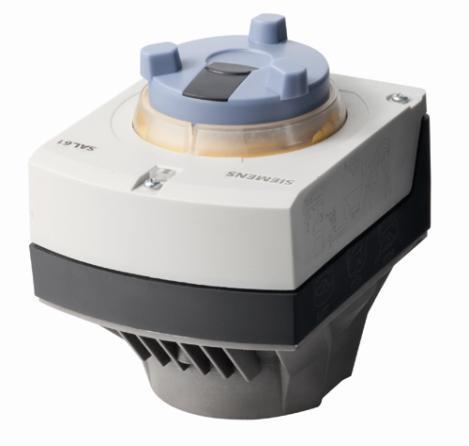
8 2 Engineering 2.1 Product description The line of large actuators is comprised of stroke actuators SAX.., SAY.., SAV.. and rotary actuators SAL.. Mechanical design 1 User interface and electrical connections 2 Power transmission and preparation 3 Yoke (for assembly of actuator and seat, slipper or butterfly valve) Components Pag e A Manual adjuster (with slide switch) 60 B Cable glands (M20 / M25) Wiring (installation) 40 C Position indication 61 D Status indication 61 E Housing cover Spare parts 20 Removal / fitting 33 F Valve stem coupling G Yoke Coupling 60 H Valve neck coupling 8 / 76 Building Technologies Engineering
9 2.2 Use SAX.., SAV.. SAY.. SAL.. Note For use in connection with Siemens 2-port or 3-port valves with 20/40 mm stroke, as control or shutoff valves for HVAC plants. For the operation of Siemens combi valves of type VPI46.40F9.5Q and VPI46.50F12Q with 15 mm stroke as control valves in ventilation, air conditioning, and district heating systems. For use in connection with Siemens butterfly or slipper valves, as control or shutoff valves for HVAC plants. When using the actuators outdoors, weather shield ASK39.1 must be fitted. 2.3 Type summary Stroke actuators Product no. Stock no. Stroke SAX31.00 SAX31.03 SAX61.03 SAX61.03U SAX81.00 SAX81.03 SAX81.03U SAV31.00 SAV61.00 SAV61.00U SAV81.00 SAV81.00U S55150-A105 S55150-A106 S55150-A100 S55150-A100-A100 S55150-A102 S55150-A103 S55150-A103-A100 S55150-A112 S55150-A110 S55150-A110-A100 Pos. force 20 mm 800 N 40 mm 1600 N Operating voltage AC 230 V AC 24 V /DC 24 V AC 230 V AC 24 V /DC 24 V Positioning signal 3-position DC 0 10 V DC 4 20 ma position 3-position DC 0 10 V DC 4 20 ma Spr. ret. time - Pos. time 120 s 30 s 120 s 30 s s LED - Manual adjuster Press and fix Press and fix S55150-A111 S55150-A111-A100 3-position - - Extra functions - Position feedback, forced control, change of characteristic - Position feedback,forced control, change of characteristic SAV..: This product line of actuators might not be available in all countries. Please talk to your local contact or consult your local internet pages of Building Technologies Engineering / 76
10 2.3.2 Stroke actuators combi valves Product no. SAY31P03 SAY61P03 SAY61.03U SAY81P03 SAY81.03U SAX31P03 Stock no. S55150-A132 S55150-A133 S55150-A135 S55150-A134 S55150-A136 S55150-A118 Stroke Pos. force 15 mm 500 N Operating voltage AC 230 V AC 24 V /DC 24 V AC 230 V SAX61P03 S55150-A mm 500 N AC 24 V /DC 24 V Positioning signal 3-Point DC 0 10 V DC 4 20 ma Spr. ret. time Pos. time - 30 s 3-Point - 3-position DC 0 10 V DC 4 20 ma s SAX81P03 S55150-A116 3-position - SAV31P00 S55150-A121 AC 230 V SAV61P00 S55150-A mm 1100 N AC 24 V /DC 24 V 3-position DC 0 10 V DC 4 20 ma s SAV81P00 S55150-A120 3-position - - LED - - Manual adjuster Press and fix Press and fix Press and fix - Extra functions Position feedback, forced control, change of characteristic - - Position feedback, forced control, change of characteristic - - Position feedback, forced control, change of characteristic Rotary actuators Product no. Stock no. Angular rotation Torque Operating voltage Positioning signal Spr. ret. time Pos. time SAL31.00T10 S55162-A Nm SAL31.00T20 S55162-A Nm 120 s AC 230 V 3-position SAL31.00T40 S55162-A Nm SAL31.03T10 S55162-A s 10 Nm SAL61.00T10 S55162-A100 DC 0 10 V SAL61.00T20 S55162-A Nm 120 s 90 DC 4 20 ma - SAL61.00T40 S55162-A Nm SAL61.03T10 S55162-A101 AC 24 V 30 s 10 Nm SAL81.00T10 S55162-A104 DC 24 V SAL81.00T20 S55162-A Nm 120 s 3- position SAL81.00T40 S55162-A Nm SAL81.03T10 S55162-A Nm 30 s LED - Manual adjuster Press and fix Extra functions - Position feedback, forced control / 76 Building Technologies Engineering


11 2.4 Ordering Example Product no. Stock no. Description Quantity SAX81.03 S55150-A103 Actuator 1 ASZ7.5/1000 S55845-Z106 Potentiometer 1 Delivery Scope of delivery Actuators, valves and accessories are supplied in individual packs. Type Device Screws Waveinset SAY..P U01 SAX U01 SAV U32 SAL..T SAL..T20 2 pcs. M5 x 20 mm 1 pc. 11 mm SAL..T40 2 pcs. M6 x 20 mm 1 pc. 14 mm ASK31N 4 pcs. M6 x 16 mm 1 pc. M5 x 20 mm incl. nut 1 pc. 12 mm 1 pc. 12 mm ASK33N 4 pcs. M6 x 16 mm 1 pc. M5 x 20 mm incl. nut 1 pc. 12 mm 1 pc. 12 mm ASK35N 2 pcs. M8 x 50 mm 1 pc. M5 x 20 mm incl. nut 1 pc. 12 mm 1 pc. 16 mm 16 mm 4040U19 12 mm 11 / 76 Building Technologies Engineering
12 2.5 Equipment combinations Stroke actuators 3-port valves Stroke 20 mm 40 mm Typical applications Stroke actuators Data Sheet Positioning force 800 N 1600 N Heating plants Ventilation and air conditioning plants Heat generation Heat distribution District heating plants SAX.. SAV.. N4501 N4503 SAX.. Valves Basic Doc. (P4030) 5) p max p max [kpa] [kpa] p max 5) [kpa] Valves Data Sheet Valve type DN k vs [m 3 /h] PN6 N4410 VXF ) 7) / 3 / 5 / 7.5 VXF ) 7) / 4 / 6.3 / 10 VXF ) / 19 VXF ) 7) / VXF ) VXF ) VXF ) VXF ) VXF ) C 4) VXF ) PN6 N4401 VXF ) / 4 / 6.3 / VXF ) / VXF VXF VXF C VXF PN10 N4420 VXF ) 7) / 4 VXF ) 7) 25 5 / 7,5 VXF ) 7) / 10 VXF ) 7) / VXF ) 7) / 25 VXF ) VXF ) VXF ) VXF ) VXF ) C 4) VXF ) PN 10 N4402 VXF ) / VXF ) / VXF ) / 25 VXF VXF VXF VXF VXF C 4) VXF PN16 N4430 VXF ) 7) / 2.5 / 3 / 4 VXF ) 7) 20 5 / 6.3 / 7.5 / VXF ) 7) / 16 / 19 / VXF ) 7) / 40 VXF ) 7) / C 4) VXF ) 7) / PN16 N4440 VXF ) 7) / VXF ) 7) 25 5 / VXF ) 7) / C 4) VXF ) 7) / SAV..: This product line of actuators might not be available in all countries. Please talk to your local contact or consult your local internet pages of SAV U32 p max [kpa] 12 / 76 Building Technologies Engineering
13 Stroke 20 mm 40 mm Typical applications Stroke actuators Data Sheet Positioning force 800 N 1600 N Heating plants Ventilation and air conditioning plants Heat generation Heat distribution District heating plants SAX.. SAV.. N4501 N4503 SAX.. Valves Basic Doc. (P4030) 5) p max p max [kpa] [kpa] p max 5) [kpa] Valves Data Sheet Valve type DN k vs [m 3 /h] PN16 N4403 VXF ) / 2.5 / 4 VXF VXF ) / VXF ) / 25 VXF ) / VXF ) / VXF ) / VXF ) / VXF ) / C 4) VXF ) / PN16 N4404 VXF VXF VXF VXF C 4) VXF PN25/16 6) N4405 VXF ) / 2,5 / 4 VXF VXF ) / VXF VXF ) / VXF PN25 6) VXF VXF VXF VXF C 4) VXF PN16 N VXG ) VXG ) VXG41.15 VXG ) VXG41.20 VXG ) VXG41.25 VXG ) VXG41.32 VXG ) VXG41.40 VXG ) C 4) VXG41.50 VXG ) ) 2) 3) 4) SAV.. p max [kpa] Insert running number instead of k vs value.. = insert k vs value With tight bypass; VXG and VXG : use only SAX61.., SKD32.50 or SKD For media temperatures > 130 C use electrohydraulic actuators SKD.. (N4561), SKB.. (N4564). 4040U32 5) 6) 7) p max = max. permissible differential pressure in diverting mode DN 15 50: Flange dimensions for PN 16 and PN 25 DN : Flange dimensions only for PN 25 Valves no longer in the active sale 13 / 76 Building Technologies Engineering
14 2.5.2 Stroke actuators 2-port valves Typical applications Stroke actuators Data Sheet Heating plants SAX.. N4501 Ventilation and air conditioning SAV.. N4503 plants Heat generation Heat distribution District heating plants Stroke 20 mm 40 mm Positioning force 800 N 1600 N 4040U32 Valves Valves Basic Doc. (P4030) Data Sheet Valve type DN k vs [m 3 /h] p s [kpa] p max [kpa] p s [kpa] PN6 N4310 VVF ) 4) / 3 / 5 / 7,5 VVF ) 4) / 4 / 6.3 / VVF ) 4) / 19 VVF ) 4) / VVF ) VVF ) VVF ) VVF ) C 3) VVF ) VVF ) PN6 N4401 VVF ) / 4 / 6.3 / VVF ) / VVF VVF SAX.. SAV.. p max [kpa] VVF ) C VVF ) PN10 N4320 VVF ) 4) / 4 VVF ) 4) 25 5 / 7, VVF ) 4) / 10 VVF ) 4) / VVF ) 4) / 25 VVF ) VVF ) VVF ) VVF ) C 3) VVF ) VVF ) PN10 N4402 VVF ) / 2.5 / VVF ) / VVF ) / VVF VVF VVF ) VVF ) VVF C 4) VVF ) PN16 N4330 VVF ) 4) / 2.5 / 3 / VVF ) 4) 20 5 / 6.3 / 7.5 / VVF ) 4) / 16 / 19 / VVF ) 4) / VVF ) 4) / C 3) VVF ) 4) / PN16 N4340 VVF ) VVF ) C 3) SAV..: This product line of actuators might not be available in all countries. Please talk to your local contact or consult your local internet pages of / 76 Building Technologies Engineering
15 Typical applications Stroke actuators Data Sheet Heating plants SAX.. N4501 Ventilation and air conditioning SAV.. N4503 plants Heat generation Heat distribution District heating plants Stroke 20 mm 40 mm Positioning force 800 N 1600 N 4040U32 Valves Basic Doc. (P4030) p s p max p s p max Valves Data Sheet Valve type DN k vs [m 3 /h] [kpa] [kpa] [kpa] [kpa] PN16 N4403 VVF ) 15 1,6 / 2,5 / 4 VVF , VVF ) 25 6,3 / VVF VVF ) / VVF ) 50 31,5 / VVF ) / VVF ) / VVF ) / VVF ) / C 3) VVF ) / PN16 N4403 VVF K VVF K VVF K VVF K VVF K C 3) VVF K PN16 N4404 VVF ) / VVF ) / VVF ) / VVF ) / C 3) VVF ) / PN25 N / 0.2 / 0.25 / VVF ) 4) / 0.4 / / 0.8 / 1 / 1.25 / 1.6 / / 2.5 / 3.2 / 4 VVF ) 4) 25 5 / 6.3 / 8 / C 3) VVF ) 4) / 16 / 20 / PN25/16 N / 0,2 / 0.25 / VVF ) 0.32 / 0,4 / 0.5 / / 0,8 / 1 / 1.25 / / 2 / 2.5 / 3.2 / VVF VVF ) 25 5 / 6.3 / 8 / VVF VVF ) / 16 / 20 / VVF ) / PN25 VVF ) VVF ) VVF VVF C 3) VVF PN16 N4363 VVG ) / 1 VVG VVG VVG VVG VVG VVG VVG C 3) VVG SAV..: This product line of actuators might not be available in all countries. Please talk to your local contact or consult your local internet pages of 1) 2) 3) 4) SAX.. SAV.. insert running number instead of k vs value.. = insert k vs value For media temperatures > 130 C use electrohydraulic actuators SKD.. (N4561), SKB.. (N4564). valves no longer in the active sale 15 / 76 Building Technologies Engineering
![2.5.3 Stroke Acutuators combi valves PN25 N4855 PN16 N4315 PN25 N4315 Valves Actuators SAY..P.. SAX..P.. SAV..P.. DN H 100 p max p s p max p s p max p s Standard flow rate High flow rate [mm] [kpa] [kpa] [kpa] [kpa] [kpa] [kpa] VPI46.](/docs-images/66/55713569/images/16-0.jpg "40F9.5Q - 40 VPI46.50F12Q - 50 15 400 400 - - - - VPF43.50F16 VPF43.50F25 50 VPF43.65F24 VPF43.65F35 65 20 - - 600 600 - - VPF43.80F35 VPF43.80F45 80 VPF43.100F70 VPF43.100F90 100 40 VPF43.")
16 2.5.3 Stroke Acutuators combi valves PN25 N4855 PN16 N4315 PN25 N4315 Valves Actuators SAY..P.. SAX..P.. SAV..P.. DN H 100 p max p s p max p s p max p s Standard flow rate High flow rate [mm] [kpa] [kpa] [kpa] [kpa] [kpa] [kpa] VPI46.40F9.5Q - 40 VPI46.50F12Q VPF43.50F16 VPF43.50F25 50 VPF43.65F24 VPF43.65F VPF43.80F35 VPF43.80F45 80 VPF43.100F70 VPF43.100F VPF43.125F110 VPF43.125F VPF43.150F160 VPF43.150F VPF53.50F16 VPF53.50F25 50 VPF53.65F24 VPF53.65F VPF53.80F35 VPF53.80F45 80 VPF53.100F70 VPF53.100F VPF53.125F110 VPF53.125F VPF53.150F160 VPF53.150F Rotary actuators slipper and butterfly valves Rotary Angular rotation 90 Typical applications actuators Data Sheet Torque 10 Nm 20 Nm 40 Nm Heating plants SAL.. N4502 Ventilation and air conditioning plants Heat generation Heat distribution District heating plants SAL..T10 SAL..T20 SAL..T40 Mounting Slipper valves Data Sheet Valve type DN k vs[m 3 /h] set p max [kpa] PN6 N4241 VBF ) VBF ) VBF ASK31N VBF ASK31N VBF ASK31N VBF ASK31N 1 C C VBF ASK31N Butterfly valves p s [kpa] PN16 N4131 VKF ) ASK33N VKF ) ASK33N VKF ) ASK33N 500 VKF ) ASK33N - - VKF ) ASK33N VKF ) ASK33N 300 VKF ) ASK33N C 120 C VKF ) ASK33N PN16 N4136 VKF ) VKF ) VKF ) VKF ) VKF ) C 120 C VKF ) ) 2) 3) 4) SAL..T10 rotary actuators only fit on VBF21.., DN For VBF21.., DN40/50 use SQK34.., SQK84.. or SQK33.00 rotary actuators. VKF41.. maximum flow speed with SAL.T10 actuator with water DN40.. DN125 = 4 m/ VKF41.. maximum flow speed with SAL.T0 actuator with water DN150/200 = 2.5 m/s, with SAL.T40 actuator with water DN150/200 = 4 m/s VKF46.. maximum flow speed water = 4.5 m/s, air 40 m/s 16 / 76 Building Technologies Engineering
17 2.6 Accessories Electrical accessories Product no. Auxiliary switch ASC10.51 Potentiometer ASZ7.5/.. 1) Function module AZX61.1 Stem heating element ASZ6.6 Stock no. S55845-Z103 S55845-Z104 (ASZ7.5/135) S55845-Z105 (ASZ7.5/200) S55845-Z107 S55845-Z108 S55845-Z106 (ASZ7.5/1000) Max. 2 Max. 1 SAX31.. Max. 1 - SAX61.. Max. 2 - Max. 1 Max. 1 SAX81.. Max. 1 - SAX31P.. Max. 1 - SAX61P.. Max. 2 - Max. 1 - SAX81P.. Max. 1 - SAV31.. Max. 1 - SAV61.. Max. 2 - Max. 1 Max. 1 SAV81.. Max. 1 - SAV31P.. Max. 1 - SAV61P.. Max. 2 - Max. 1 - SAV81P.. Max. 1 - SAL31.. Max. 1 - SAL61.. Max. 2 - Max. 1 - SAL81.. Max. 1 - SAY31P.. Max. 1 - SAY61P.. Max. 2 - Max. 1 - SAY81P.. Max. 1-1) Available with 135, 200 or Mechanical accessories Product no. Weather shield Mounting set ASK39.1 ASK31N for VBF21.. ASK33N for VKF41.. ASK35N für VKF45.. 1) Stock no. S55845-Z109 S55845-Z100 S55845-Z101 S55845-Z102 SAY.. SAX.. SAV.. SAL.. Max SAL..T10 - Max. 1 SAL..T DN40...DN65 SAL..T40 - DN150 / 200 DN80 DN200 1) In 2000 VKF45.. line was replaced by VKF46.. line. 17 / 76 Building Technologies Engineering
18 2.7 Product replacements Replacement of SQX.. / SQL.. actuators by SAX.. / SAL.. actuators. Note When replacing actuators consider positioning force, torque and positioning times. Adjust in the controller the parameter "Running time" respectively "Positioning time", to ensure stable control. The replacement of accessory items needs to be taken into consideration also. In that case, compatibility is not necessarily ensured Stroke actuators SQX.. to SAX.. SQX.. SAX.. 1) VVF21../VXF21.. Pos. time [s] Pos. force [N] Pos. time [s] Pos. force [N] VVF31../VXF31.. VVF40../VXF40.. VVF41../VXF41.. VVG41../VXG41.. VVF51.. VVF52.. DN15 80 DN15 50 DN15 40 SQX31.. 2) SQX SAX SQX SAX SQX61.. SQX SAX SQX61U SAX61.03U SQX81.. SQX SAX SQX81.00U SAX81.00U SQX SAX SQX81.03U SAX81.03U SQX32.. SQX SAX SQX SAX SQX62.. SQX SAX SQX62U SAX61.03U SQX82.. SQX SAX SQX82.00U SAX81.00U SQX SAX SQX82.03U SAX81.03U ) 2) SAX81.., SAX61.. are available as UL-listed versions. SQX31.06: Actuator for gas valves. Either replace complete valve-actuator combination or clarify required positioning time and replace only actuator. Consider if mounting set is required Rotary actuators SQL.. to SAL.. SQL.. SAL.. Pos. time [s] Torque [Nm] Pos. time [s] Torque [Nm] SQL31.. SQL ,5 SAL31.00T SQL32.. SQL ,5 SAL31.00T SQL ,5 SAL31.00T10 or SAL31.03T10 1) SQL SAL31.03T SQL33.. SQL ,5 SAL31.00T SQL SAL31.03T SQL83.. SQL ,5 SAL81.00T SQL SAL81.03T SQL35.. SQL SAL31.00T20 2) SQL SAL31.00T40 2) SQL85.. SQL SAL81.00T20 2) SQL SAL81.00T40 2) ) 2) SAL.. positioning time differs from that of SQL32.12 and SQL32.13 rotary actuators. Consider positioning time when replacing. use SAL.T20 on VKF46.40, VKF46.50 and VKF46.65 use SAL.T40 on VKF46.80, VKF and VKF / 76 Building Technologies Engineering
19 Rotary actuators SQL.. SAL.. SAL31.00T10 SAL31.03T10 SQL33.. SQL35.. SAL81.00T10 SAL31.00T20 SAL31.00T40 SQL31.. SQL32.. SQL83.. SQL85.. SAL81.03T10 SAL81.00T20 SAL81.00T40 VBF21.. DN 40 / DN 50 1) - - ASK ) - 1) - 1) DN ASK31 - ASK31N - - VBF31.. DN 40 / DN 50 2) - - ASK ) - 2) - 2) DN ASK31 - ASK31N - - B3f.. DN 40 / DN 50 2) Direct ASK25 ASK DN Direct ASK25 ASK31 - ASK31N - - C1f.. DN 40 / DN 50 2) Direct - ASK DN Direct - ASK31 - ASK31N - - K1i.. DN Direct ASK24 ASK33 - ASK33N - - K1f.. DN Direct ASK24 ASK33 - ASK33N - - VKF41.. DN ASK33 - ASK33N - - DN 150 / DN ASK33 ASK35 ASK33N - ASK33N VKF45.. DN ASK35 - ASK35N ASK35N DN ASK35N 1) N4506). 2) Replace with rotary actuators SQK34.., SQK84.. (data sheet N4508) or SQK33.00 (data sheet Replace with rotary actuators SQK ASK32 Note Rotary actuators SAL.. are not suited for mounting sets ASK24, ASK25, ASK31, ASK32, ASK33, ASK35, ASK40 and ASK Electrical accessories Notes If an auxiliary switch is required, its switching point should be indicated on the plant schematic. For media below 0 C the stem heating element ASZ6.6 keeps the valve free from freezing. For this case, do not insulate the actuator bracket and the valve stem, as air circulation must be ensured! Non-observance of the above may result in accidents and fires! Do not touch the hot parts without prior protective measures to avoid burns. Stroke actuators SQX.. SAX.. SQX31.. SQX61.. SQX32.. SQX62.. SAX31.. SAX61.. SQX SQX SAX ASZ6.5 Stem heater ASZ6.5 ASZ6.5 ASZ6.5 ASZ6.5 ASZ6.6 ASZ6.6 ASZ7.4 1 auxiliary switch, ASC ASZ7.4 - ASZ7.4-1 potentiometer (1000 ) ASZ7.5/ ASC9.4 Double auxiliary switch ASC9.4 - ASC9.4-2x ASC ASC9.5 Auxiliary switch ASC9.5 - ASC9.5 - ASC Rotary actuators SQL.. SAL.. SQL31.. SQL32.. SQL SAL31..T SQL SAL81..T SQL SAL31.00T20 / T SQL SAL81.00T20 / T40 ASZ7.4 1 auxiliary switch, ASC ASC ASZ7.4 ASZ7.4 1 potentiometer (1000 ) ASZ7.5/1000 ASZ7.5/1000 ASC9.4 Double auxiliary switch - - ASC9.4 ASC9.4 2x ASC x ASC10.51 ASC9.5 Auxiliary switch - - ASC9.5 ASC9.5 ASC10.51 ASC10.51 ASZ8.4 Potentiometer (220 ) ASZ8.4 ASZ ) - ASZ9.4 Potentiometer (2800 ) ASZ9.4 ASZ ) - ASC1.4 Auxiliary switch ASC1.4 ASC ASC ) Used auxiliary switches or potentiometer (order accessories additionally were applicable): Check used functionality Check compatibility with controller 19 / 76 Building Technologies Engineering
20 2.8 Spare parts The following spare part sets are available: SAY.., SAX.., SAV.. Stock number Housing cover Screw (valve stem coupling) U-bracket Single components from the spare part sets are not available. SAL.. Stock number Housing cover 2 adapters 4 screws 1 pc. 14 mm 1 pc. 11 mm Single components from the spare part sets are not available. 2.9 Sizing 2 pcs. M5 x 20 mm 2 pcs. M6 x 20 mm Parallel operation of actuators SA and SA SA position actuators must have one specific controller each, refer to "Connection diagrams" (page 69). Up to 10 actuators can drive in parallel on a controller output with a rating of 1 ma. Modulating actuators have an input impedance of 100 k. 20 / 76 Building Technologies Engineering
21 2.9.2 Permissible cable lengths and wire cross-sectional areas Cable lengths and wire cross-sectional areas depend on the following criteria of the actuators: Current draw Permissible voltage drop across the power supply lines Note The control accuracy of the modulating actuators can be improved by using 4-wire connections, thus ensuring that voltage drops on G0 will not distort the positioning signal. When determining the cable length and the wire cross-sectional area, adherence to the permissible operating voltage tolerance at the actuator is of importance, in addition to the permissible voltage drop across the operating voltage and signal lines (see table below). Product no. Operating voltage Terminal Max. permissible voltage drop SA AC 230 V N, Y1, Y2 2% each (total of 4%) SA G0, G 4% each (total of 8%) AC/DC 24 V G0, Y, U 1% each (at DC 0 10 V) SA G, Y1, Y2 4% each (total of 8%) The following criteria must be considered: With modulating control, the permissible positioning signal error must not exceed 1%, the reason being the voltage drop on the G0 wire. The voltage drop, caused by charging current peaks in the actuator s DC circuit, must not exceed 2 Vpp. If the G0 line is not correctly sized, load changes of the actuator due to changes of the DC voltage drop might lead to self-oscillations. The operating voltage drop at AC/DC 24 V may be a maximum of 8% (4% above the G0 wire). Basic diagram voltage drop across the power supply cables The following diagram can be used to determine the cable lengths and wire crosssectional areas. 21 / 76 Building Technologies Engineering
22 L/P-diagram for AC/DC 24 V Cable length L Power Consumption P Permissible cable length L as a function of power P and cross-sectional area of wire as a parameter Note Formulas for wire lengths P is the decisive power consumption of all actuators connected in parallel. When operating on AC 24 V, power consumption is in VA; when operating on DC 24 V, in W. Operating voltage Permissible voltage drop / wire Formula for wire length AC 230 V 2% of AC 230 V L = 46 AC/DC 24 V 4% of AC 24 V L = 1% of DC 10 V L = A Cross-sectional area of wire in mm 2 L Permissible wire length in m P Power consumption in VA (AC) or W (DC) (see actuator s rating plate) I(DC) DC current part (in A) on G0 wire 1313 A 1313 A P 5.47 A I (DC) P m m m 2.10 Warranty The engineering data specified in chapter "Equipment combinations" (page 12) are only guaranteed in connection with the Siemens valves listed. Note When using the actuators in connection with valves of other manufacture, correct functioning must be ensured by the user, and Siemens will assume no responsibility. 22 / 76 Building Technologies Engineering
23 3 Handling 3.1 Mounting and installation Mounting positions Indoor use Outdoor use 1) 1) Only in connection with weather shield ASK Fitting stroke actuators to seat valves VVF.. / VXF.. or VVG.. / VXG.. First, observe "Mounting positions" (page 23). Caution! Risk of burns from hot surfaces! If you touch heated parts, you will get burns as result. Allow to cool parts. Wear protective gloves. 1 Actuator s stem retracted / 76 Building Technologies Handling
24 5 10 mm mm Avoid missalignement on V_G41 valves with fittings Caution! Risk of burns from hot surfaces! If you touch heated parts, you will get burns as result. Allow to cool parts. Wear protective gloves. 1 2 On threaded valves it s possible that the actuator is missaligned on the valve due to a collision with the fitting. If so, please take care for correct mounting, either by turning the actuator or by adjusting the fitting (e.g. use a second sealing to change fitting position). 24 / 76 Building Technologies Handling

25 3.1.4 Fitting rotary actuators to butterfly valves VKF41.. First, observe "Mounting positions" (page 23). Mounting set ASK33N Mounting set (2 parts) Scope of delivery 5 screws 4 pcs. M6 x 16 mm 1 pc. M5 x 20 incl. nut 1 adapter inc. fixing screw 1 adapter Note Actuators SAL.. are not compatible with mounting sets ASK31, ASK32, ASK33, ASK35, ASK40, and ASK41. Caution! Risk of burns from hot surfaces! If you touch heated parts, you will get burns as result. Allow to cool parts. Wear protective gloves mm 3 5 mm 25 / 76 Building Technologies Handling
.")
26 4 12 mm 5 5 mm mm 1) 1) Angle position errors between actuator shaft and valve stem must be corrected via manual control (refer to "Manual adjuster" page 60). 26 / 76 Building Technologies Handling

27 3.1.5 Fitting rotary actuators to slipper valves VBF21.. First, observe "Mounting positions" (page 23). Mounting set ASK31N Mounting set (2 parts) Scope of delivery 5 screws 4 pcs. M6 x 16 mm 1 pc. M5 x 20 mm incl. nut 1 adapter inc. fixing screw 1 adapter SAL..T10 rotary actuators only fit on VBF21.., DN For VBF21.., DN40/50 use SQK34.., SQK84.. or SQK33.00 rotary actuators. With VBF21.. (e.g. DN 125), the following steps must be performed prior to fitting the mounting set. Caution! Risk of burns from hot surfaces! If you touch heated parts, you will get burns as result. Allow to cool parts. Wear protective gloves. 27 / 76 Building Technologies Handling
28 1 2 Opening counterclockwise 3a 4 mm, 5 mm 3b 4 mm, 5 mm 12 mm 12 mm 28 / 76 Building Technologies Handling
29 Opening clockwise 3c 4 mm, 5 mm 3d 4 mm, 5 mm 12 mm 12 mm For further mounting positions of VBF 21.. and routing of the connection cables the rotary actuators and adapters must be mounted according to the sketches above. 29 / 76 Building Technologies Handling

30 3.1.6 Fitting rotary actuators to butterfly valves VKF46.. First, observe "Mounting positions" (page 23). Standard scope of delivery VKF46.. Product no. Scope of delivery 2 screws 1 dapter SAL..T20 2 pcs. M5 x 20 mm 1 pc. 11 mm SAL..T40 2 pcs. M6 x 20 mm 1 pc. 14 mm Caution! Risk of burns from hot surfaces! If you touch heated parts, you will get burns as result. Allow to cool parts. Wear protective gloves mm (DN 40 50) 14 mm (DN ) mm (DN 40 65) 5 mm (DN ) 30 / 76 Building Technologies Handling
31 3.1.7 Fitting rotary actuators to butterfly valves VKF45.. First, observe "Mounting positions" (page 23). Mounting set ASK35N For VKF45.. Scope of delivery Mounting set (2 parts) 5 screws 2 adapters 2 pcs. M8 x 50 mm 1 pc. M5 x 20 mm incl. nut 1 pc. 12 mm 1 pc. 16 mm 4040U U19 12 mm 16 mm Note Actuators SAL.. are not suited for use with mounting sets ASK31, ASK32, ASK33, ASK35, ASK40, and ASK41. Caution! Risk of burns from hot surfaces! If you touch heated parts, you will get burns as result. Allow to cool parts. Wear protective gloves mm (DN ) 16 mm (DN 150 / 200) 31 / 76 Building Technologies Handling
32 3 4 mm mm 4040J J52 32 / 76 Building Technologies Handling
33 3.1.8 Fitting accessories Special notes on mounting SA Before fitting the accessory items shown below, the following steps must be performed: Danger! Danger to life from electrical current! There is an immediate risk of fatal injury in case of contact with live parts of SA Disconnect actuator from power. 1. Actuator is mechanically connected to a Siemens valve. 2. Observe compatibility and choice of combinations. Refer to "Accessories" (page 17). 3. Disconnect actuator from power. 4. Only required with actuators without fail safe function: Using the manual adjuster, drive the actuator s stem to the fully retracted position and fix the coupling. See Manual operation and Fixing coupling (page 45). 5. When mounting two different accessories watch out for correct plug-in space A or B (see below). 6. To fit an auxiliary switch, potentiometer or function module, the housing cover must be removed. 1 PZ 2 2 Interior view of setting elements and plug-in spaces F E D C A B C Plug-in space for Potentiometer ASZ7.5/.., or Auxiliary switch ASC10.51 Plug-in space for Function module AZX61.1, or Auxiliary switch ASC10.51 LED D DIL switches B A 4040J39 E F Calibration slot Connection terminals 33 / 76 Building Technologies Handling
34 Potentiometer ASZ7.5/.. Scope of delivery 1 potentiometer ASZ7.5/.. 1 screw 2 screw covers 1 pc. First, observe "Special notes on mounting" (page 33). Danger! Danger to life from electrical current! If a live wire gets in contact with the screws the whole actuator housing is a live. Fit the screw covers first. Plug-in space A No.: 1 5 Turn to 0% 4040J73 34 / 76 Building Technologies Handling
35 6 No.: 2 7 Observe "Wiring" (page 40) 8 Observe "Connection terminals" (page 68) Function module AZX61.1 First, observe "Special notes on mounting (page 33). 1 Set function module (page 49) 2 Nr.: 3 Plug-in space B / 76 Building Technologies Handling
36 Auxiliary switch ASC10.51 Scope of delivery 1 auxiliary switch ASC screw 2 screw covers 1 pc. First, observe "Special notes on mounting" (page 33). Danger! Danger to life from electrical current! If a live wire gets in contact with the screws the whole actuator housing is a live. Fit the screw covers first. Plug-in space A No.: 1 5 Adjust switch position (refer also to "Manual operation" page 60) 36 / 76 Building Technologies Handling
 First, observe \"Special notes on mounting\" (page 33). Danger!")

37 6 No.:1 When initial situation: 0 When initial situation: 7 Observe "Wiring" (page 40) 8 Observe "Connection terminals" (page 68) First, observe "Special notes on mounting" (page 33). Danger! Danger to life from electrical current! If a live wire gets in contact with the screws the whole actuator housing is a live. Fit the screw covers first. Plug-in space B No.: 1 37 / 76 Building Technologies Handling
 8 Observe \"Connection terminals\" (page")
38 5 Adjust switch position (refer also to "Manual operation" page 60) 6 No.: 1 When initial situation: 0 When initial situation: 7 Observe "Wiring" (page 40) 8 Observe "Connection terminals" (page 68) 38 / 76 Building Technologies Handling
. 1 10 mm 14 mm 2 3 4 8 mm Weather shield ASK39.")
39 Stem heating element ASZ6.6 Scope of delivery 1 stem heating element ASZ6.6 1 screw 1 pc. M4 x 30 incl. nut When fitting the stem heating element, stroke actuator and valve must be assembled. The stem heating element is powered separately. First, observe "Special notes on mounting (page 33) mm 14 mm mm Weather shield ASK39.1 First, observe "Special notes on mounting (page 33). Scope of delivery Weather shield ASK UV-proof cable ties Notes To protect the actuator when used outdoors, the weather shield must always be fitted. If fitted several times, 2 UV-proof cable ties (800 x 4 mm) must be used. The manual adjuster cannot be used when the weather shield is mounted / 76 Building Technologies Handling

 Metric Metric Inch thread M20 M25 ½ Prior to installation, the")
. Actuator 1 No.")
40 3.1.9 Wiring (installation) Conduct the electrical connections in accordance with local regulations on electrical installations as well as the "Connection diagrams" on page 68. Preparation of wire endings The cable endings must be prepared before as follows. A B EU: M20 US: ½ EU: M25 US: ½ Standard Ground cable for outdoor installation Connection actuator C EU: M20 US: ½ Connection accessorie s Cable glands (not contained in scope of delivery) Metric Metric Inch thread M20 M25 ½ Prior to installation, the following preconditions must be satisfied: Actuator is mechanically connected to a Siemens valve. Housing cover is removed (step 6 "Special notes on mounting", page 33). Actuator 1 No.: J Observe "Connection terminals" (page68) 4040J78 40 / 76 Building Technologies Handling
41 Auxiliary switch ASC No.: 4 2 and Potentiometer ASZ7.5/ J Observe "Connection terminals" (page68) 4040J J81 41 / 76 Building Technologies Handling
42 3.2 Commissioning and operation Function check and Calibration Mechanically Before making the function check, the following preconditions must be satisfied: Environmental conditions specified in chapter "Technical data" (page 64) Actuator is mechanically connected to a Siemens valve Actuator is in "Manual operation" mode (page 60). The actuator can be operated with the help of the "Manual adjuster" (see page 60). Manual adjuster Turning in clockwise direction Turning in counterclockwise direction Stroke actuator Actuator s stem extends Actuator s stem retracts Rotary actuator Actuator s spindle turns in clockwise direction Actuator s spindle turns in counterclockwise direction Control path valve A AB Opening Closing Bypass valve B AB Closing Opening Notes Electrically SA General notes on calibration Ensure that the actuator s and valve s stem, or actuator s and valve s spindle are securely connected in all positions. If the actuator is forced to travel beyond its end positions, overload protection responds. Observe information given in chapter "Acting direction and flow characteristic" on page 53. Before making the function check, the following preconditions must be satisfied: Environmental conditions specified in chapter "Technical data" (page 64). Actuator is mechanically connected to a Siemens valve. Actuator is in "Automatic" mode (page 60). Actuator and, if required, accessories are correctly fitted and connected. Also refer to "Connection terminals" (page 68). Power is applied. Calibration is required with modulating actuators and SA before the function check. Before making the calibration, the following preconditions must be satisfied: A description of the calibration function is given in chapter "Calibration" (page 53). Housing cover is removed (step 6 "Special notes on mounting", page 33). 1 Bridge contact 2 Check LED (page 61) 4040J40 If required, calibration can be repeated any number of times. 42 / 76 Building Technologies Handling
43 Make the function check for modulating actuators after the calibration with a point test according to the following table: Y Y Connection terminals 6 V 13.6 ma 5 V 12 ma Z connected to G Z connected to G0 Stroke actuator Actuator s stem extends (60%) Actuator s stem retracts (50%) Actuator s stem extends Actuator s stem retracts Rotary actuator Actuator s spindle turns in clockwise direction (60 %) Actuator s spindle turns in counterclockwise direction (50 %) Actuator s spindle turns in clockwise direction Actuator s spindle turns in counterclockwise direction Control path valve A AB Bypass valve B AB Opening Closing 6 V Closing Opening 5 V Opening Closing 10 V Closing Opening 0 V Position feedback U SA and SA Make the function check for 3-position actuators according to the following table: Connection terminals Stroke actuator Rotary actuator Voltage at Y1 Voltage at Y2 No voltage at Y1 and Y2 Actuator s stem extends Actuator s stem retracts Actuator s stem maintains the position Actuator s spindle turns in clockwise direction Actuator s spindle turns in counterclockwise direction Actuator s spindle maintains the position Control path valve A AB Opening Closing Bypass valve B AB Closing Opening Maintains the position Notes Auxiliary switch ASC10.51 If function module AZX61.1 is used, observe information given in chapter "Changeover of acting direction" (page 51). Observe information given in chapter "Acting direction and flow characteristic" on page 53. Make the function check for mounted auxiliary switches according to the following table example switching point at 25% position: Connection terminals Voltage at Y2 No voltage at Y1 und Y2 Voltage at Y1 for desired valve position % + 2% x positioning time Example: SAX31.00 = 27% x 120 sec = 32.5 sec Y = 0 V Y = 0 V Check switching point with voltmeter Valve position % + 2% Y = 2.7 V Stroke actuator Actuator s stem retracts (until end position is reached) Actuator s stem maintains the position Actuator s stem extends to desired position (27%) Actuator s stem maintains the position Rotary actuator Actuator s spindle turns in counterclockwise direction (until end position is reached) Actuator s spindle maintains the position Actuator s spindle turns in clockwise direction to desired position (27%) Actuator s spindle maintains the position Terminal S1 S3 Terminal S1 S / 76 Building Technologies Handling
44 Potentiometer ASZ7.5 Make the function check for mounted potentiometer according to the following table (Example values for ASZ7.5/1000): Connection terminals Voltage at Y2 No voltage at Y1 und Y2 Voltage at Y1 for desired valve position % positioning time Example: SAX31.00 = 75% x 120 sec = 90 sec Check position value with ohmmeter Voltage at Y2 for desired change of valve position % x positioning time Example: SAX31.00 = 10% x 120 sec = 12 sec Check position value with ohmmeter Stroke actuator Actuator s stem retracts (until end position is reached) Actuator s stem maintains the position Actuator s stem extends to desired position (75%) Actuator s stem maintains the position Actuator s stem retracts to desired position (65%) Actuator s stem maintains the position Rotary actuator Actuator s spindle turns in counterclockwise direction (until end position is reached) Actuator s spindle maintains the position Actuator s spindle turns in clockwise direction to desired position (75%) Actuator s spindle maintains the position Actuator s spindle turns in counterclockwise to desired position (65%) Actuator s spindle maintains the position Terminal P1 P2 Terminal P2 P3 - - < 1 > ~ 560 ~ ~ 485 ~ Maintenance The actuators are maintenance-free Disposal The device is considered an electronics device for disposal in terms of European Directive 2012/19/EU and may not be disposed of as domestic garbage. Dispose of the device through channels provided for this purpose. Comply with all local and currently applicable laws and regulations. 44 / 76 Building Technologies Handling


45 4 Functions and control position control A 3-position signal drives the actuator via connection terminals Y1 or Y2. The required position is transferred to the valve. 1 A/D conversion Identification of seat Control Control of direction 2 functions Motor control Manual adjustment 3 Brushless DC motor 4 Gear train Manual adjuster Positioning signal Voltage at Y1 Voltage at Y2 No voltage at Y1 and Y2 Stroke actuator Actuator s stem extends Actuator s stem retracts Actuator s stem maintains the position Rotary actuator Actuator s spindle turns in clockwise direction Actuator s spindle turns in counterclockwise direction Actuator s spindle maintains the position Control path valve A AB Opening Closing Bypass valve B AB Closing Opening Maintains the position Note Observe information given in chapter "Acting direction and flow characteristic" on page 53. Internal control ensures very constant positioning times and determination of the actuator s position. 45 / 76 Building Technologies Functions and control
46 Positioning times stroke model The specified positioning times refer to the respective nominal stroke / nominal angular rotation. Since the end positions of rotary actuators are inside the actuator, the following remarks refer to stroke actuators. The resulting effective strokes vary, depending on the type of valve, resulting in shorter or longer actuator positioning times. Stroke of valve-actuator combination [mm] Legend diagram A B A B Positioning time [sec] Mechanical end position in SAX.. / SAV.. VVF.. / VXF.. valves with 20 / 40 mm nominal stroke = k vs- value reached Internal end position of VVF.. / VXF.. valves with 20 / 40 mm nominal stroke Notes Deviations occur after several positioning signals Y1 and Y2 in the same direction since the stroke movement starts with a delay of 300 ms. when positioning signals Y1 and Y2 are active for less than 300 ms since the stroke movement cannot be made in that case. A B C Y1 Y2 0 Calculated position Actual position Positioning time [ms] Positioning signals (power applied) No power applied Accurate position feedback is made possible with the help of a potentiometer (page 62). 46 / 76 Building Technologies Functions and control
47 Notes Combination with RVD.. controller for direct domestic hot water distribution by heat exchanger The design based slow reaction on control signals of SAX31.., SAX81.., SAV31.. and SAV81.. actuators doesn t allow the actuator to react on very short control pulses. Only control pulses with a length greater than 400 ms allow a sufficient reaction. Especially the direct domestic hot water control does not allow such long control pulses. The specific optimized control loops equipped with an SIGMAGYR RVD.. controller and Acvatix SQS actuator work with pulses down to 40 ms. SAX31.. and SAX81.. are not able to work with these short pulses. The following table gives alternatives which actuators can be used within these control loops. Controller RVD130 RVD135/109 RVD135/309 RVD140 RVD144/109 RVD145/109 RVD139 RVD230 RVD235/109 RVD250 RVD255/109 RVD240 RVD245/109 RVD260 RVD265/109. Plant type 4 und 5 x- 4 Prefered actuator SQS35.03 SAS31.03 SQS SAT SQS SAT31.51 SKD32.21 Valve line DN kvs VVG55.. DN VVG549.. DN VVG549.. DN VVG41.. VVF53.. DN SKD32.21E DN SQS35.03 SAS31.03 SQS SAT SQS SAT31.51 SKD32.21 SKD32.21E VVG55.. DN VVG549.. DN VVG549.. DN VVG41.. VVF53.. VVG41.. VVF53.. DN DN / 76 Building Technologies Functions and control
 corresponds in a linear manner to the positioning range (fully closed...fully open, or 0 100 % stroke). The actuator is driven via connection terminal Y or forced control Z (page 58).")
 3 DIL switches Changeover of characteristic Positioning signal 4 Function module 5 A/D conversion 6 Power supply Identification of seat Position control Motor")

48 4.2 Modulating control The modulating positioning signal drives the actuator steplessly. The positioning signal range (DC V / DC ma, ) corresponds in a linear manner to the positioning range (fully closed...fully open, or % stroke). The actuator is driven via connection terminal Y or forced control Z (page 58). The required stroke / rotation is transferred to the valve s stem / spindle. 1 Calibration slot 2 LED (2 colors) 3 DIL switches Changeover of characteristic Positioning signal 4 Function module 5 A/D conversion 6 Power supply Identification of seat Position control Motor control 7 Control Detection of foreign bodies functions Calibration Forced control Characteristics function Manual adjustment 8 Brushless DC motor 9 Gear train Manual adjuster Positioning signal Signal Y, Z increasing Signal Y, Z decreasing Signal Y, Z constant Stroke actuator Actuator s stem extends Actuator s stem retracts Actuator s stem maintains the position Rotary actuator Actuator s spindle turns in clockwise direction Actuator s spindle turns in counterclockwise direction Actuator s spindle maintains the position Control path valve A AB Opening Closing Bypass valve B AB Closing Opening Maintains the position Notes If function module AZX61.1 is used, observe the information given in chapter "Changeover of acting direction" (page 51). Observe the information given in chapter "Acting direction and flow characteristic" on page / 76 Building Technologies Functions and control
 Direct acting positioning signal Y or Z Sequence control not active ON 1) Reverse acting")
 DIL switches Sequence control ON 1) Sequence control (signal adaptation) 1) Factory setting: All switches set")


49 4.3 Function module AZX61.1 DIL switches Acting direction Sequence control OFF 1) Direct acting positioning signal Y or Z Sequence control not active ON 1) Reverse acting positioning signal Y or Z Sequence control (signal adaptation) 1) Factory setting: All switches set to OFF Sequence control (signal adaptation) DIL switches Sequence control ON 1) Sequence control (signal adaptation) 1) Factory setting: All switches set to OFF HEX switches Nr.: 1 Setting sequence control Rotary switches LO and UP are used to set the starting point or working range of a sequence. Position Position Starting point "LO" "UP" Working range 0 0,3 V 0 9,4 V 1 1 V 1 3 V 2 2 V 2 4 V 3 3 V 3 5 V 4 4 V 4 6 V 5 5 V 5 7 V 6 6 V 6 8 V 7 7 V 7 9 V 8 8 V 8 10 V 9 9 V 9 12 V A 10 V A 14 V B 11 V B 16 V C 12 V C 18 V D 13 V D 20 V E 14 V E 25 V F 15 V F 30 V Invalid HEX switches combinations LO A B C D E F UP F F F F F F F F F F D D C C B UP E E E E E E E D D C UP F F E E D UP F F E UP F Notes Can only be used with voltage input. Maximum input voltage is DC 30 V. If the configuration is invalid, the actuator operates on DC 0 10 V. 49 / 76 Building Technologies Functions and control
50 Examples Legend diagram Positioning signal range Position LO Position UP Position feedback U A DC 2 10 V 2 6 DC 0 10 V B DC 0 5 V 0 3 DC 0 10 V C DC V C 3 DC 0 10 V H Stroke or rotary angle Acting direction: Direct (A, B, C) Acting direction: Reverse (A', B', C') 50 / 76 Building Technologies Functions and control
51 4.3.2 Changeover of acting direction DIL switches Acting direction OFF 1) Direct acting positioning signal Y or Z ON 1) Reverse acting positioning signal Y or Z 1) Factory setting: All switches set to OFF Selecting the acting direction With valves whose stem is extended in the fully closed position, "direct acting" means that the valve is fully closed (0 %) when positioning signal Y = 0 V resp. Z = 0. This applies to all Siemens valves according to "Equipment combinations" (page 12). With valves whose stem is retracted in the fully closed position, "direct acting" means that the valve is fully open (100 %) when positioning signal Y = 0 V resp. Z = 0. SAX61.03 SAV61.00 Direct acting Reverse acting SAY61P03 SAX61P03 SAV61P00 Y, Z Positioning signal V Volumetric flow Acting direction: Direct Acting direction: Reverse Positioning signal Y: Positioning signal Z: Reverse acting DC 0 10 V 4 20 ma Direct acting Positioning signal Y: Positioning signal Z: DC 0 10 V 4 20 ma / 76 Building Technologies Functions and control
 Factory setting: All DIL switches set to OFF Flow characteristic SAX61.03 / SAV61.00 with VVF.")

52 4.4 Positioning signal and flow characteristic selection DIL switches Positioning signal "Y" Position feedback "U" Flow characteristic OFF 1) DC 0 10 V DC 0 10 V log = equalpercentage ON DC 4 20 ma DC 0 10 V lin = linear 1) Factory setting: All DIL switches set to OFF Flow characteristic SAX61.03 / SAV61.00 with VVF.. Actuator Valve VVF.. / VVG41.. Totally log lin Flow characteristic SAY61P03 / SAX61P03 / SAV61P00 with VPF.. Actuator Combi-Valve VPF43/VPF53 Totally log lin Y, Z Positioning signal H Stroke V Volumetric flow Acting direction: Direct Acting direction: Reverse 52 / 76 Building Technologies Functions and control
 and the associated type of valve (valve characteristic, push to open, pull to open). When the positioning signal increases (DC 0 10 V, DC 4 20 ma, 0.")

53 4.5 Acting direction and flow characteristic The selection of changeover of acting direction and characteristic with the DIL switches depends on the type of actuator (with or without fail safe function) and the associated type of valve (valve characteristic, push to open, pull to open). When the positioning signal increases (DC 0 10 V, DC 4 20 ma, ), the objective is to have the valve s volumetric flow V rising, but to fully open the valve, V = 100 % (NO = normally open), or to fully close it, V = 0 % (NC = normally closed) in the event of a power failure. DIL switches Without fail safe function Acting direction Flow characteristic No power applied Linear Direct Linear Maintains the position Reverse Equalpercentage Equalpercentage 4.6 Position Feedback U The position feedback U (DC V) is always proportional to stroke H of the actuator s stem. Actuator Positioning signal Y, Z Actuator Position feedback U log = equalpercentage lin = linear 53 / 76 Building Technologies Functions and control
54 Actuator Positioning signal Y, Z Actuator Position feedback U Direct acting Reverse acting Y, Z Positioning signal H Stroke U Position feedback Acting direction: direct Acting direction: reverse 4.7 Position control with ClosedPosition- Synchronisation Within SAX/SAV/SAL61/SAY61.. actuators the position control works based on the HALL-sensor pulses from the brushless DC-motor calculating with an internal stroke model calculating the actual position. This kind of control is more accurate and wearless compared with a physical element for position measurement and grants a precise position control with high resolution. During manual operation the motor is declutched from the gear train and the internal position control get s not sensor pulses. So real position will deviate from the internally calculated position. As a consequence the position feedback on terminal U is set to 0V during manual operation. To grant after manual operation that real mechanical position and internal position control are matching all SA operate after manual operation an automatic ClosedPosition-Synchronisation ClosedPosition-Synchronisation Returned into automatic operation the actuator runs for s into opening direction to grant secure closed-position detection. Then the actuator runs into closed position (seat A-AB in the valve). Reaching the closed position the internal stroke model is synchronized. Positioning signal, position feedback and meachnical position now match perfectly again. With this function it s granted that the position feedback U which was zero during manual operation and synchronization - always represents the real mechanical position of the actuator. 54 / 76 Building Technologies Functions and control
55 After synchronization the actuator follows the control signal again Active forced position input on Z If after return to automatic mode a signal on Z is active (GND, AC/DC 24 V or Ohm) the ClosedPosition-Synchronisation is deactivated as long as the signal on Z remains. After Z is deactivated the ClosedPosition-Synchronisation will be performed. Note ClosedPosition-Synchronisation is only automatically activated after manual operation. A power failure does not activate this function automatically, to avoid that all actuators in a section close in parallel. If the customer likes synchronization also after a power failure he should take care that the plant restarting routine drives the actuator automatically into an end position. This will also synchronies the internal position control and the real position. 55 / 76 Building Technologies Functions and control
56 4.8 Calibration To match the actuator to production-related mechanical tolerances of the individual valves, accurate positioning and position feedback must be ensured, if calibration is performed when the plant is commissioned (page 42). During commissioning, the actuator detects the valve s end positions and files the exact stroke in its internal memory. Calibration takes place in the following phases: Actuator drives to H 0 (1), valve closes. Detection of upper end position. Actuator drives to H 100 (2), valve opens. Detection of lower end position. The detected values are stored (3). Then the actuator follows the positioning signal. Note Observe status indication (LED) during and after calibration (page 61). If the actuator does not detect the second end position within an appropriate stroke range (max. 25 mm), the first end stop will be adopted and the actuator operates with a working range of 20 mm. 4.9 Signal priorities The actuators are controlled via different interlinked positioning signal paths (positioning signal Y, forced control input Z, manual adjuster). The signal paths are assigned the following priorities: Priority 1 (highest) 2 3 (lowest) Description The manual adjuster always has priority 1, thus overriding all signals active at Z or Y, independent of whether or not power is applied. Only SA..61..: As soon as a valid positioning signal is active at input Z, the position is determined via positioning signal Z (forced control). Prerequisite: The manual adjuster is not used. The position is determined via positioning signal Y. The manual adjuster is not used and on Z there is no active signal. Z Y Examples Manual adjuster Automatic mode Automatic mode Automatic mode Operated (30%) and engaged Forced control (Z) Not connected Positioning signal (Y) 5 V Stroke actuator Actuator s stem travels to position (50%) G 3 V Actuator s stem extends G0 3 V Actuator s stem retracts G 8 V Bold printing = positioning signal currently active Actuator s stem retracts manual (to 30%) Rotary actuator Actuator s spindle travels to position (50%) Actuator s spindle turns in clockwise direction Actuator s spindle turns in counter-clockwise direction Actuator s spindle turns manual in counterclockwise direction (to 30%) 56 / 76 Building Technologies Functions and control
57 4.10 Detection of valve seat The actuators feature force-dependent valve seat detection. After calibration, the exact valve stroke is filed in the actuator s memory. When the actuator reaches the respective end of stroke, it does not hit the valve s seat at full speed, but stops for 5 seconds at about 1% before the stored position is reached. If the positioning signal stays at 0% or 100%, the actuator travels to the calculated end position at reduced positioning speed and builds up the required nominal force. This function extends the actuator s service life since the dynamic forces are reduced when approaching the valve seat and there will be less strain on the gear train. In addition, the actuator s oscillations in the case of instable control are suppressed. If no force is built up in the calculated end position (e.g. in the event of temperature effects for instance), the actuator continues to operate at a reduced positioning speed until the nominal positioning force is restored. This ensures that the valve always fully closes. After a power failure, valve seat identification is not active the actuators define their stroke position on power resoration to be at 50%. From now on, the actuator follows the positioning signal. When the valve plug reaches its seat for the first time, the actuator readjusts its stroke model. Example The supposed position is 50%, Y = 2 V, the actuator travels 30% of the stored valve stroke in the direction of "Actuator s stem retracted". If the actuator reaches the seat within this 30% travel, it interprets the position as "Valve fully closed" and shifts the position of the valve s stroke accordingly without changing the extent of travel. From now on, the actuator follows the changed valve stroke position. This means: New position 0%, Y = 2 V, actuator travels 20% of the stored valve stroke in the direction "Actuator s stem extended" Detection of foreign bodies The actuator detects when the valve is clogged and adjusts its operational behavior accordingly to prevent damage to itself or the valve. If the actuator hits an obstacle within the calibrated stroke and is not able to overcome it with its nominal positioning force, it stores the position at which the obstacle was hit. Depending on the direction of travel, as "Lower limit of valve clogging", if the clogging was detected when traveling in the direction of "Actuator s stem retracting". "Upper limit of valve clogging", if the clogging was detected when traveling in the direction of "Actuator s stem extending". Now, the status LED blinks green and the actuator only follows the positioning signal between the positions "Actuator s stem retracted" and "Upper limit of valve clogging" or "Actuator s stem extended" and "Lower limit of valve clogging". After detection of clogging, 3 attempts are made to overcome clogging by traveling about 15% in the opposite direction and then trying again to overcome the position of clogging. If the attempts made are unsuccessful, the actuator continues to follow the positioning signal within the restricted range only and the LED continues to blink green (refer to "Indicators" on page 61). 57 / 76 Building Technologies Functions and control

58 4.12 Forced control Z SA only Forced control is affected by changeover of acting direction. It uses the following operating modes: Z-mode No function Fully open Fully closed Overriding positioning signal Y by Transmission Connections Equal-percentage or linear characteristic Contact Z not connected, valve follows positioning signal Y Contact Z is connected directly to G, positiong signal Y has no impact Contact Z is connected directly to G0, positiong signal Y has no impact Equal-percentage or linear characteristic Contact Z is connected to M via resistor R, starting point at 50, end point at 900, positioning signal Y has no impact Note The operating modes "Z" shown are based on factory setting "direct acting" and a "push to open" valve. 58 / 76 Building Technologies Functions and control
.")

59 4.13 Technical and mechanical design Transmission of power Function principle Incoming positioning signals are translated to positioning commands for the motor. A gear train transmits the motor s positioning steps to the output stage (valve coupling). Attached to the gear train are the electrical and mechanical accessory items and the manual adjuster. In the case of the rotary actuators, the adjustment to the required torque is made in the output stage. With the stroke actuators, the translation from rotary to stroke movement takes place in the output stage. SAL.. SAX.., SAV.. Actuator s stem retracted / valve fully closed Actuator s stem extended / valve fully open 59 / 76 Building Technologies Functions and control
60 Coupling SAX.., SAV.. SAL.. The stem coupling (1) and neck coupling (2) ensures full backward compatibility with all types of Siemens large-stroke valves produced since Mounting sets are available for use with butterfly and slipper valves Manual adjuster Automatic When the motor drives the manual adjuster turns. Thus in automatic mode, the manual adjuster is used for indication of travel. If the manual adjuster is held firm in this mode, there is no transmission of power to the gear train. Manual operation When pushing the manual adjuster down (1), it engages and the actuator can be manually operated. Stroke actuator: When turning the manual adjuster in clockwise / counterclockwise direction (2), the actuator s stem retracts / extends. Rotary actuator: The actuator spindle turns in the same direction. An overload protection prevents damage to the manual adjuster Fixing the position Upon actuation and locking the slide switch, the manual adjuster remains engaged. When in this mode, do not turn the manual adjuster. Disengaging the fixing When resetting the slide switch, the manual adjuster returns to automatic mode. ->The modulating SA will automatically start a Zero Position Synchronisation 60 / 76 Building Technologies Functions and control
61 Indicators A Indication of travel B C Scale Indicator Position indication D LED Status indication Operational status indication Position indication In Automatic mode, the manual adjuster serves for the indication of travel. See "Automatic" (page 60). Position indication is on 2 opposite sides. When turning the manual adjuster, the indicator moves in the same direction. The scale indicates the stroke. When reaching the stops, the valve is either fully open or fully closed. Status indication (LED) Housing cover fitted Housing cover removed When the housing cover is fitted, the LED can be viewed through a light conductor. When the housing cover is removed, the LED can be viewed through a hole. The status indication informs about the operational state of the actuator. LED Indication Operating state Remarks, troubleshooting On Automatic mode Normal operation Blinking Calibration (page 42). Wait until calibration is finished Green (then green or red light) In manual mode Manual adjuster in MAN position Detection of foreign bodies Check valve / actuator (page 57) Red On Calibration error Start calibration again (page 42) Blinking Clogged valve Check valve Dark Dark No power or electronics faulty Check operating voltage 61 / 76 Building Technologies Functions and control
62 Electrical accessories Auxiliary switch ASC10.51 The auxiliary switch ASC10.51 switches on or off when a certain position is reached. The switching point can be set between 0 100%. AC 24 V V / 6 (2) A S1 S3 S2 Switching point for S1 S2 and S1 S3 cannot be set separately. If S1 S2 is open then S1 S3 is closed. point Adjustable switching Application example: When using an auxiliary switch, position feedback can trigger an automatic stop of the circulating pump in the end position "Fully closed". Potentiometer ASZ7.5/.. Potentiometer ASZ7.5/.. (1000, 200, 135 ) delivers an ohmic value to the controller giving the exact position of the actuator (continuous position feedback). A slip clutch prevents damage to the potentiometer in the mechanical end positions. This is also used for accurate balancing of the potentiometer in the fully closed position Ohmic value between P2-P1 increases with stroke H or rotation, ohmic value between P2-P3 decreases. Flow characteristic The end values of the potentiometers refer to the maximum stroke / maximum angular rotation of the actuators. For this reason, the resulting values in operation deviate, depending on the type of valve used in combination with the actuator. The potentiometer's starting point can be very accurately adjusted during installation (refer page 34). SAX.. SAV.. SAL.. ASZ7.5/135 ASZ7.5/200 ASZ7.5/ Ohm at nominal stroke/nominal angular rotation 154 Ohm at nominal stroke/nominal angular rotation 770 Ohm at nominal stroke/nominal angular rotation R = Ohm x nominal stroke/nominal angular rotation (%) R = Ohm x nominal stroke/nominal angular rotation (%) R = Ohm x nominal stroke/nominal angular rotation (%) R = Ohm x stroke (mm) R = Ohm x stroke (mm) R = Ohm x stroke (mm) R = Ohm x stroke (mm) R = Ohm x stroke (mm) R = Ohm x stroke (mm) R = Ohm x rotary angle ( ) R = Ohm x rotary angle ( ) R = Ohm x rotary angle ( ) Potentiometer measuring value [ohm] Actuator position in relation to nominal stroke/nominal angular rotation [%] 62 / 76 Building Technologies Functions and control
63 Function module AZX61.1 Function module AZX61.1 offers the following choices for changing control: Changeover of acting direction (page 51) Sequence control (page 49) Stem heating element ASZ6.6 Stem heating element ASZ6.6 prevents the formation of ice on the stem when medium temperatures drop below 0 C. It is suited for universal use with valves having a stem diameter of 10 or 14 mm. The stem heating element heats up to 120 C. This is a PTC element, which means it shows up with a low resistance at power up inrush current may reach 13 A at low temperatures / high voltage level Mechanical accessories Weather shield ASK39.1 Weather shield ASK39.1 protects the actuator when installed outdoors. This does not lead to a change of IP class (IP54). Mounting sets ASK3..N Mounting sets ASK31N, ASK33N and ASK35Nenable the actuators to be fitted to slipper valves VBF21.., DN and butterfly valves VKF41.. and VKF45 (page 25-32). 63 / 76 Building Technologies Functions and control
64 5 Technical data Power supply Operating voltage SAY.. SAX.. SAV.. SAL.. SA AC 230 V ± 15 % SA AC 24 V ± 20 % / DC 24 V + 20 % / -15 % (SELV) SA AC 24 V ± 20 % / DC 24 V + 20 % / -15 % (SELV) Frequenz 45 65Hz External supply line protection (EU) 6 A...10 A slow Circuit breaker max. 13 A Characteristic B, C, D according to EN Power source with current limitation of max. 10 A Power consumption at 50 Hz SAX31.00 Stem retracts / extends 3.5 VA / 2 W SAX31.03 Stem retracts / extends 6 VA / 3.5 W SAX Stem retracts / extends 8 VA / 3.75 W Holding state 3.5 VA / 1.5 W - - SAX Stem retracts / extends 3.5 VA / 2.25 W SAX Stem retracts / extends 5 VA / 3.75 W SAV Stem retracts / extends 6.5 VA / 4 W SAV Stem retracts / extends VA / 4.5 W - SAV Stem retracts / extends 7 VA / 4.5 W SAL31.00T10 Rotary actuator turns 3.5 VA / 2 W SAL31.00T20 Rotary actuator turns 4.5 VA / 2.75 W SAL31.00T40 Rotary actuator turns 7 VA / 4 W SAL31.03T10 Rotary actuator turns 5.5 VA / 3.25 W SAL61.00T10 Rotary actuator turns Holding state 5 VA / 2.5 W 3.5 VA / 1.5 W SAL61.00T20 Rotary actuator turns 6 VA / 2.75 W Holding state 3.5 VA / 1.5 W - - SAL61.00T40 Rotary actuator turns 9 VA / 4 W Holding state 3.5 VA / 1.5 W SAL61.03T10 Rotary actuator turns Holding state 7.5 VA / 3.5 W 3.5 VA / 1.5 W SAL81.00T10 Rotary actuator turns 3 VA / 2 W SAL81.00T20 Rotary actuator turns 4 VA / 2.75 W SAL81.00T40 Rotary actuator turns 6 VA / 3.75 W SAL81.03T10 Rotary actuator turns 5 VA / 3.5 W SAY31P03 Stem retracts / extends 6 VA / 3.5 W SAY61P03 Stem retracts / extends 8 VA / 3.75 W Holding state 3.5 VA / 1.5 W SAY61.03U Stem retracts / extends 8 VA / 3.75 W Holding state 3.5 VA / 1.5 W SAY81P03 Stem retracts / extends 5 VA / 3.75 W SAY81.03U Stem retracts / extends 5 VA / 3.75 W 64 / 76 Building Technologies Technical data
65 Function data Signal inputs Parallel operation Forced control Position feedback Connecting cable Degree of protection Environmen tal conditions SAY.. SAX.. SAV.. SAL.. Positioning times with specified nominal stroke / nominal angular rotation SAX..00, SAV.., SAL s 120 s 120 s SAY..03, SAX..03, 30 s 30 s - 30 s SAL..03 Positioning force 200 N 800 N 1600 N - Torque SAL..T Nm running SAL..T20 4) Nm running SAL..T40 4) Nm running Nominal stroke 15 mm 20 mm 40 mm - Angular rotation Positioning signal Y SA..31.., SA position SA Voltage AC 230 V ± 15 % SA Voltage AC 24 V ± 20 % / DC 24 V + 20 % / -15% SA (DC V) Current draw 0,1 ma Input impedance 100 k SA (DC ma) Current draw DC 4 20 ma ± 1 % Input impedance 500 SA (depending on controller output) Positioning signal Z SA R = R= , G, G0 Stroke / rotation proportional to R Z connected to G Max. stroke 100% 1) 90 1) Z connected to G0 Min. stroke 0% 1) 0 1) Voltage Max. AC 24 V ± 20 % Max. DC 24 V + 20 % / -15% Current draw 0,1 ma Position feedback U SA DC 0 10 V ± 1 % Load impedance >10 k res. Load Max. 1 ma Wire cross-sectional areas mm 2, AWG ) Cable entries SA.. EU: 2 entries 20.5 mm (for M20) 1 entry 25.5 mm (for M25) SA..U US: 3 entries 21.5 mm for ½ tube connection Housing from vertical to horizontal IP54 as per EN ) Insulation class As per EN Actuators SA AC 230 V II Actuators SA AC / DC 24 V III Actuators SA AC / DC 24 V III Operation IEC Climatic conditions Class 3K5 Mounting location Indoors (weather-protected) Temperature General C C Humidity 5 95 % r.h. (noncondensing) Transport IEC Climatic conditions Class 2K3 Temperature C Humidity <95 % r.h. Storage IEC Climatic conditions Class 1K3 Temperature C Humidity 5 95 % r.h. Max. media temperatur when mounted on valve 120 C 130 C 130 C 5) 120 C 1) 2) 3) 4) 5) Observe acting direction of DIL switches AWG = American wire gauge Also with weather shield ASK39.1 SAL.T20 / T40 have a minimum holding torque of 14 Nm Up to 150 C with horizontal mounting position 65 / 76 Building Technologies Technical data
66 Directives and Standards Environmental compatibility Product standard SAY.. SAX.. SAV.. SAL.. EN60730-x CE1T4503xx 1) Electromagnetic compatibility For residential, commercial and industrial environments (Application) EU Conformity (CE) A5W ) CE1T4501x1 1) CE1T4502X1 1) CE1T4501x2 1) CE1T4502X2 1) RCM Conformity AC 230 V A5W ) CE1T4515X4 1) CM1T4503_C1 1) - UL, cul AC 230 V - AC/DC 24 V UL The product environmental declarations contain data on environmentally compatible product designs and assessments (RoHS compliance, materials composition, packaging, environmental benefit, disposal): Ben 1) Ben 1) A 1) CE1E4502en 1) Dimensions See "Dimensions" (page 70) Weight Excl. packaging See "Dimensions" (page 70) Accessories Potentiometer ASZ7.5/ ± 5 % 2) Voltage DC 10 V (SELV) Current rating < 4 ma Potentiometer ASZ7.5/ ± 5% Voltage DC 10 V (SELV) Current rating < 4 ma Potentiometer ASZ7.5/ ± 5% Voltage DC 10 V (SELV) Current rating < 4 ma Auxiliary switch ASC10.51 AC V, 6 (2) A, floating Switching capacity External supply line protection US installation, UL & cul See section power supply AC 24 V class 2, 5 A general purpose Stem heating element ASZ6.6 AC / DC 24 V Power supply Power consumption 40 VA / 30 W at 50 Hz Inrush current (cold) Max. 13 A Function module AZX61.1 for SA Switching capacity External supply line protection US installation, UL & cul 1) AC V, 6 (2) A, floating See section power supply AC 24 V class 2, 5 A general purpose The documents can be downloaded from 2) UL recognized component 66 / 76 Building Technologies Technical data
67 6 Connection diagrams and dimensions 6.1 Internal diagrams SA Accessories A and / or B 1x ASC10.51 AC 24 V V / 6 (2) A S1 1x ASC10.51 AC 24 V V / 6 (2) A S1 S3 S2 or 1 x ASZ7.5/.. S3 S2 SA Accessories A and / or B 1x ASC x ASC10.51 AC 24 V V / 6 (2) A S1 AC 24 V V / 6 (2) A S1 S3 S2 S3 S2 SA Accessories A and / or B 1x ASC10.51 AC 24 V V / 6 (2) A S1 M 1x ASC10.51 AC 24 V V / 6 (2) A S1 S3 S2 or 1 x ASZ7.5/.. AC/DC 24 V S3 S2 67 / 76 Building Technologies Connection diagrams and dimensions
 Positioning signal (actuator s stem extends / actuator s spindle turns clockwise) Positioning signal (actuator s stem retracts / actuator s spindle turns")
 System potential (SP) Positioning signal for DC 0 10 V / 4 20 ma Measuring neutral Position feedback DC 0.")
68 6.2 Connection terminals Actuators SA AC 230 V, 3-position System neutral (SN) Positioning signal (actuator s stem extends / actuator s spindle turns clockwise) Positioning signal (actuator s stem retracts / actuator s spindle turns counter-clockwise) SA SA AC/DC 24 V, DC 0 10 V / 4 20 ma / Sytem neutral (SN) System potential (SP) Positioning signal for DC 0 10 V / 4 20 ma Measuring neutral Position feedback DC V - (reference potential is M measuring neutral) Positioning signal forced control AC/DC 24 V, AC/DC 24 V, 3-position System potential (SP) Positioning signal (actuator s stem extends / actuator s spindle turns clockwise) Positioning signal (actuator s stem retracts / actuator s spindle turns counter-clockwise) Electrical accessories Auxiliary switch ASC10.51 Adjustable switching points, AC V System potential (SP) Closing Contact Opening Contact Switching state allway s related to extending actuator stem or clockwise turning actuator s spindle turns AC 24 V V / 6 (2) A S1 S3 S2 Potentiometer ASZ7.5/.. Adjustment of zero point, DC 10 V Measuring neutral 0 x x 0 x = 135, 200 ;1000 Stem heating element ASZ6.6 AC 24 V / 30 W / 40 VA / inrush current max. 13A System neutral (SN) (red) System potential (SP) (black) 68 / 76 Building Technologies Connection diagrams and dimensions
2- and 3-port valves with flanged connections, PN 10
 4 402 VVF32.. VXF32.. ACVATIX 2 and 3port valves with flanged connections, PN 10 From the largestroke valve line VVF32.. VXF32.. Performance valves for medium temperatures from 10 150 C Valve body of grey
Butterfly Valves PN 6/10/16 for flanged connection
 4 136 ACVATIX Butterfly Valves PN 6/10/16 for flanged connection tight-closing VKF46.. VKF46..TS Grey cast iron housing EN-GJL-250 (to DN 300) nodular cast iron housing EN-GJS-400-15 (from DN 350) DN 40
Air damper actuators
 4 634 OpenAir TM Air damper actuators GDB...1 GLB...1 Rotary version, / AC 230 V Electronic motor driven actuators for three-position and modulating control Nominal torque 5 Nm (GDB), 10 Nm (GLB) Mechanically
Electric Rotary Actuator - On/Off or programmable control actuator
 Electric Rotary Actuator - On/Off or programmable control actuator Direct mounting on quarter-turn valves Manual override standard Corrosion resistant Adjustable limit switches Multi-voltage version Type
225-230T-05-S2. Rotary drive without spring return. Technical data sheet. Description. Technical data. Actuators
 Actuators Technical data sheet 225-230T-05-S2 Rotary drive without spring return Description Actuator for adjusting air dampers of 90 angle of rotation to be used in HVAC installations. Torque Motor 5
Electrical data Nominal voltage AC/DC 24 V Nominal voltage frequency
 echnical data sheet NV24A--RE Communicative globe valve actuator for 2-way and 3-way globe valves Actuating force 1000 N Nominal voltage AC/DC 24 V Control Modulating DC (0)2...10 V Variable Nominal stroke
SKP Series SKP15U.. Gas Valve Actuator with Safety Shutoff Function
 SKP Series SKP15U.. Gas Valve Actuator with Safety Shutoff Function Document No. 155-751 SKP15U.. Description Only when assembled to Series VGU Gas valves SKP15 electro-hydraulic actuators combine with
225C-024T-05. Continuous control rotary drive without spring return. Technical data sheet. Description. Technical data. Actuators
 Actuators Technical data sheet 225C-024T-05 Continuous control rotary drive without spring return Description Actuator for adjusting air dampers of 90 angle of rotation to be used in HVAC installations.
Rotary actuator for 2 and 3-way (control) ball valves Torque 5 Nm Nominal voltage AC 100... 240 V Control: Open/close or 3-point Auxiliary switch
 ball valves Torque 5 Nm Nominal voltage AC 100... 240 V Control: Open/close or 3-point Auxiliary switch") echnical data sheet Rotary actuator LR-S Rotary actuator for and -way (control) ball valves orque 5 Nm Nominal voltage C... 4 V Control: Open/close or -point uxiliary switch echnical data Electrical data
echnical data sheet Rotary actuator LR-S Rotary actuator for and -way (control) ball valves orque 5 Nm Nominal voltage C... 4 V Control: Open/close or -point uxiliary switch echnical data Electrical data
SEZ220. Signal Converter. Synco 200. With preprogrammed standard applications Freely programmable Menu-driven operation. Use
 s 5 146 Synco 200 Signal Converter SEZ220 With preprogrammed standard applications Freely programmable enu-driven operation Use The signal converter is for use in HVAC plant to provide minimum / maximum
Actuator for modulating control AME 435
 Data sheet Actuator for modulating control AME 435 Description The actuator automatically adapts its stroke to the valve end positions which reduces commissioning time (self stroking). The advanced design
N20xxA, N34xxA NON-SPRING RETURN DIRECT-COUPLED DAMPER ACTUATORS FOR FLOATING AND 2-POSITION CONTROL
 N2xxA, N34xxA NON-SPRING RETURN DIRECT-COUPLED DAMPER ACTUATORS FOR FLOATING AND 2-POSITION CONTROL SPECIFICATIONS Supply voltage N224A / N3424A N223A / N3423A PRODUCT DATA 24 Vac 15%, 5/6 Hz 23 Vac 15%,
FDCI222, FDCIO222, FDCIO224 Input module Input/output modules
 FDCI222, FDCIO222, FDCIO224 Input module Input/output modules addressable (FDnet/C-NET) Sinteso Cerberus PRO Input module FDCI222 with 4 monitored contact inputs for the acknowledgement of technical states
Elektromotoren und Gerätebau Barleben GmbH
 Elektromotoren und Gerätebau Barleben GmbH OPERATING INSTRUCTIONS Transformer Protection Relay NM Series (Buchholz principle) Elektromotoren und Gerätebau Barleben GmbH Table of contents Page 1. Safety
Power consuption Motor (Motion) Power consuption Standby (end position) 1,0 W. Position feedback - Switching point 0...95
 Power consuption Standby (end position) 1,0 W. Position feedback - Switching point 0...95") Actuators Technical data sheet 227S-230-05-S1 Rotary drive without spring return Description Actuator for adjusting air dampers of 90 angle of rotation to be used in HVAC installations. Torque Motor 5
Actuators Technical data sheet 227S-230-05-S1 Rotary drive without spring return Description Actuator for adjusting air dampers of 90 angle of rotation to be used in HVAC installations. Torque Motor 5
Input module, input/output module
 Sinteso / Cerberus PRO Input module, input/output module FDCI221, FDCIO221 Input module and input/output module for the automatically addressed detector line Input module FDCI221: Monitorable contact input
Elektromotoren und Gerätebau Barleben GmbH
 Elektromotoren und Gerätebau Barleben GmbH OPERATING INSTRUCTIONS Transformer Protection Relay (Buchholz principle) Elektromotoren und Gerätebau Barleben GmbH Table of contents Page 1 Safety instructions
RRV934. Multi-controller. Synco living
 s 2 709 Synco living Multi-controller RRV934 RF-based multi-controller For precontrol of up to 2 room groups For control of ventilation plant with up to 3 stages RF communication based on KNX standard
Technote. Frese OPTIMA Compact actuators DN10-DN32. Application. Features thermic actuators. Features motoric actuators. Approval. www.frese.
 Page 1 of 6 Application Proportional 0-10V or 3-position modulating or On/ Off control of Frese OPTIMA Compact valves in heating, ventilating and air conditioning systems. The actuator can be mounted on
Addendum to the Operating Instructions
 Drive Technology \ Drive Automation \ System Integration \ Services Addendum to the Operating Instructions MOVIMOT with AS-Interface and AC Motor DT/DV Unit Replacement MOVIMOT MM..C -> MM..D with MLK3A
HERZ-Thermal Actuators
 HERZ-Thermal Actuators Data Sheet 7708-7990, Issue 1011 Dimensions in mm 1 7710 00 1 7710 01 1 7711 18 1 7710 80 1 7710 81 1 7711 80 1 7711 81 1 7990 00 1 7980 00 1 7708 11 1 7708 10 1 7708 23 1 7709 01
ABB Drives. User s Manual. Pulse Encoder Interface Module RTAC-01
 ABB Drives User s Manual Pulse Encoder Interface Module RTAC-0 Pulse Encoder Interface Module RTAC-0 User s Manual 3AFE 64486853 REV A EN EFFECTIVE:.5.00 00 ABB Oy. All Rights Reserved. Safety instructions
Digital input modules
 8 172 TX-I/O Digital input modules TXM1.8D TXM1.16D Two fully compatible versions: TXM1.8D: 8 inputs, each with a three-color LED (green, yellow or red) TXM1.16D: As TXM1.8X, but 16 inputs, each with a
TA-FUS1ON. Fully adjustable Kvs control and balancing valves. That s just two good.
 TA-FUS1ON Fully adjustable Kvs control and balancing valves. That s just two good. Supported by the Reece hvac-r network. Through our 36 stores around Australia, Reece hvac-r is committed to supporting
VC Series Zone Valves BALANCED 2-WAY AND 3-WAY HYDRONIC VALVES
 VC Series Zone Valves BALANCED 2-WAY AND 3-WAY HYDRONIC VALVES PRODUCT DATA Design VC Series zone valves consist of: 2-way or 3-way valve housing available with various connection ends Spindle and cartridge
QFP910. Water detector. Building Technologies. CE1N2732en 2016-03-01. Synco living
 2 732 Synco living Water detector QFP910 Wireless radio sensor to record water puddles RF communication based on KNX standard (868 MHz unidirectional) Battery operation with standard 1.5 V batteries Use
HP UPS R1500 Generation 3
 HP UPS R1500 Generation 3 Installation Instructions Part Number 650952-001 NOTE: The rating label on the device provides the class (A or B) of the equipment. Class B devices have a Federal Communications
I nstallation. M100Q Series Proportional Actuator with R81Q Controller Board for Thermistor Sensor Applications. Tools Needed.
 FANs 268.1, 1628.3 Installation Bulletin M100Q Issue Date 1099 M100Q Series Proportional Actuator with R81Q Controller Board for Thermistor Sensor Applications I nstallation Parts Included M110QGA-1 and
V47 Series Temperature Actuated Modulating Water Valves
 V47 Series Temperature Actuated Modulating Water Valves Master Catalog 125 Valves, Miscellaneous (Other Than Gas) Section V Product Bulletin V47 Issue Date 0286 Application The V47 modulating valves regulate
Product and Applications Description. Application Programs. Example of Operation. GAMMA instabus Technical Product-Information.
 Product and Applications Description The power supply units N 125/x2 can supply DC 24 V power from an additional pair of terminals (yellowwhite). This DC 24 V output voltage can be used to power e.g. an
Modular I/O System Analog and Digital Interface Modules
 OPERATING INSTRUCTIONS Modular I/O System Analog and Digital Interface Modules Installation Operation Maintenance Document Information Document ID Title: Operating Instructions Modular I/O System Part
Custom configuration such as modified angle dimensions, other flange standards, 3-way function, alternative materials.are available on request.
 LEAKVALVE: HIGHLIGHTS The core of this valve is a diaphragm in stainless steel 316L, gold plated. Robust, it cannot be damaged with any normal methods. The dead volume is kept as small as possible. There
Infrarot-Bewegungsmelder IP44
 Infrarot-Bewegungsmelder IP44 infrared motion sensors IP44 ODA (weiß) slim ODA (schwarz) slim 95174 96000 ODA (weiß) ODA (schwarz) 95175 96001 Betriebsanleitung User s Manual User s Manual infrared motion
Air damper actuators Rotary version, two-position control, with spring return, AC 24 V or AC 230 V
 4 613 OpenAir TM Air damper actuators Rotary version, two-position control, with spring return, AC 24 V or AC 230 V GCA12...1 GCA32...1 Electromotive rotary actuators for two-position control, nominal
How To Drive A Compact Serie 1
 Electric lifting cylinder Compact Series Table of Contents Glossary... 2 Compact serie SR 1... 4 Dimension SR 1... 5 Compact Serie SR 1SP... 6 Dimension SR 1SP... 7 Compact Serie SR 5... 8 Dimension SR
Hydraulic Control Solutions
 Hydraulic Control Solutions Vexve s Hydrox hydraulic control solutions are suitable for even the most challenging installation sites and conditions. Specifically designed for district heating and district
FLUORESCENT UV- RING LIGHT OPERATING INSTRUCTION
 FLUORESCENT UV- RING LIGHT OPERATING INSTRUCTION Caution! UV-radiation of this device is in the range of UV-A (320-400 nm). Direct exposure to eyes shall therefore be avoided. UV protection glasses shall
Data sheet ECC 12 and 22
 Application ECC is an electronic room temperature controller for water-based systems. ECC can control - fan-coil units - inductions units - air conditioning systems - small ventilating systems - 2-pipe
S03, S05 Series Low-Torque Spring- Return Direct-Coupled Actuators
 S, S Series Low-Torque Spring- Return Direct-Coupled Actuators S, S, S, S, S, S INSTALLATION AND OPERATING INSTRUCTIONS S, S Series Low-Torque Spring-Return Direct-Coupled Actuators (DCA) are used for
TX OPEN RS232/485 module
 s 8 185 8185P01 TX-I/O ; DESIGO OPEN TX OPEN RS/485 module for integrating third-party systems and devices to DESIGO (V4 or higher) TXI1.OPEN Platform to integrate third-party systems and devices to the
Duct Humidity Transmitter
 SDC-H Duct Humidity Transmitter Features Replaceable sensor element Humidity measurement for air ducts Minimum and maximum value memory 0 0V, 0 0mA or 0V, 4 0mA measuring signals selectable with jumpers
Machine needle shut-off nozzle type HP
 Machine needle shut-off nozzle type HP pneumatically or hydraulically controlled Index of contents Chapter Page Safety instructions... 2 Installation instructions... 3 - Installation steps... 3 Initial
Type overview. Technical data
 Technical data sheet R3..xx-S.. Characterised control valve, 3-way, Internal thread For closed cold and warm water systems For modulating water-side control of air handling units and heating systems ir
RVL470. Heating Controller. Building Technologies HVAC Products. Series B
 2 522 Heating Controller Series B RVL470 Multifunctional heating controller for use in residential and non-residential buildings; suitable for weather-dependent flow temperature control of heating zones
DRM75A 230V 20/100A DIN rail single phase two wire energy meter
 DRM75A 230V 20/100A DIN rail single phase two wire energy meter 1.1 Safety instruction 1.2 Foreword 1.3 Performance criteria 1.4 Specifications 1.5 Basic errors 1.6 Description 1.7 Dimensions 1.8 Installation
R.C.C.B. s two-pole LEXIC
 87045 LIMOGES Cedex Telephone : (+33) 05 55 06 87 87 Fax : (+ 33) 05 55 06 88 88 R.C.C.B. s two-pole LEXIC 089 06/09/10/11/12/15/16/17/18/ 27/28/29/30/35, CONTENTS PAGES 1. Electrical and mechanical characteristics...
MINIMAT-EC-Servo Screwdriver Spindles
 Screwdriving technology Automation Air motors Air tools Screwdriver Spindles electric MINIMAT-EC-Servo Screwdriver Spindles Maximum Flexibility and process Control Straight Spindle Form - Torque range
Accessory Manual Ventilation Section Model Comfort Circle
 Accessory Manual Ventilation Section Model Comfort Circle Manual version:. R a Copyright and trademarks All the information and drawings in this manual are the property of Biddle and may not be used (other
WE-350 Series ¼ Turn Electric Actuator
 WE-350 Series ¼ Turn Electric Actuator Operation and Installation Manual Pg 1 (Rev. 020113) Table of Contents 1.0 General 1.1 Pre-Installation Inspection 1.2 Storage 1.3 Features & General Information
Pneumatic Control and Shut-off Butterfly Valve Pfeiffer Type BR 14b/31a and Type BR 14c/31a
 Pneumatic Control and Shut-off Butterfly Valve Pfeiffer Type BR 14b/31a and Type BR 14c/31a Application Tight-closing, double eccentric butterfly valve for process engineering and plants with industrial
aseries A13B Mini Bullet Camera User Manual
 aseries A13B Mini Bullet Camera User Manual Thank you for purchasing our product. If there are any questions, or requests, please do not hesitate to contact the dealer. This manual applies to the MicroView
ABB Drives. User s Manual HTL Encoder Interface FEN-31
 ABB Drives User s Manual HTL Encoder Interface FEN-31 HTL Encoder Interface FEN-31 User s Manual 3AUA0000031044 Rev B EN EFFECTIVE: 2010-04-06 2010 ABB Oy. All Rights Reserved. 5 Safety instructions
OWNER S MANUAL FORCE 10 MARINE COMPANY 23080 HAMILTON ROAD RICHMOND, BC CANADA V6V 1C9 TEL: (604) 522-0233 FAX: (604) 522-9608
 522-0233 FAX: (604) 522-9608") Electric Water Heater OWNER S MANUAL FORCE 10 MARINE COMPANY 23080 HAMILTON ROAD RICHMOND, BC CANADA V6V 1C9 TEL: (604) 522-0233 FAX: (604) 522-9608 If your water Heater is Damaged or you have questions
Electric Water Heater OWNER S MANUAL FORCE 10 MARINE COMPANY 23080 HAMILTON ROAD RICHMOND, BC CANADA V6V 1C9 TEL: (604) 522-0233 FAX: (604) 522-9608 If your water Heater is Damaged or you have questions
The table below lists the symbols used on the Clamp and/or in this manual. Important Information. See manual.
 i800 AC Current Clamp Instruction Sheet Introduction The i800 AC Current Clamp, the Clamp, has been designed for use with multimeters, recorders, power analyzers, safety testers, etc., for accurate non-intrusive
Ambient Temperature Sensor TEMPSENSOR-AMBIENT
 Ambient Temperature Sensor TEMPSENSOR-AMBIENT Installation Guide TempsensorAmb-IEN110610 98-0042210 Version 1.0 EN SMA Solar Technology AG Table of Contents Table of Contents 1 Notes on this Guide...............................
ADM1TE 5/30A DIN rail single phase two wire energy meter
 ADMTE 5/30A DIN rail single phase two wire energy meter. Safety instruction.2 Foreword.3 Performance criteria.4 Specifications.5 Basic errors.6 Description.7 Dimensions.8 Installation.9 Operating.0 Troubleshooting.
TIG INVERTER INSTRUCTION MANUAL
 TIG INVERTER INSTRUCTION MANUAL Contents Warning General Description Block Diagram Main Parameters Circuit Diagram Installation and Operation Caution Maintenance Spare Parts List Troubleshooting 3 4 4
Differential Pressure Sensors for air and non-corrosive gases, with calibration certificate
 1 919 1919P01 1919P03 QBM65/C, QBM75-1U/C Differential Pressure Sensors for air and non-corrosive gases, with calibration certificate QBM751-1/C QBM65/C QBM75/C Highly accurate measurements with calibration
Art.S001-S002 SOLAR MODULE WITH DELIVERY AND RETURN CONNECTIONS
 Art.S001-S002 SOLAR MODULE WITH DELIVERY AND RETURN CONNECTIONS Technical Information sheet 0001/07/Rev01 ENG FUNCTION Series S001 and S002 circulation units are applied to the primary circuit of solar
Automation System TROVIS 6400 TROVIS 6493 Compact Controller
 Automation System TROVIS 6400 TROVIS 6493 Compact Controller For panel mounting (front frame 48 x 96 mm/1.89 x 3.78 inch) Application Digital controller to automate industrial and process plants for general
Overview of types. Technical data
 Technical data sheet R3..xx-S.. Characterised control valves, 3-way, with internal thread For closed cold and warm water systems For modulating water-side control of HU and heating systems ir bubble-tight
Achat 115MA full-range speaker. user manual
 Achat 115MA full-range speaker user manual Musikhaus Thomann Thomann GmbH Hans-Thomann-Straße 1 96138 Burgebrach Germany Telephone: +49 (0) 9546 9223-0 E-mail: info@thomann.de Internet: www.thomann.de
Features. High Brightness LED Light source
 www.edison-opto.com Solid-State Lighting Series 6W MR16 DATASHEET Features High Brightness LED Light source Ecologically Friendly Energy Efficient General Information... 1 Product Dimensions... 2 Product
DBS720 / FDS221-R / FDS221-W Sounder base, Alarm sounders
 DBS720 / FDS221-R / FDS221-W Sounder base, Alarm sounders For the automatic addressable detector bus C-NET Cerberus PRO Sounder base DBS720 11 selectable tones, 2 programmable activation levels Sound intensity
5SV Residual Current Protective Devices
 s Siemens AG 2013 SENTRON 5SV Residual Current Protective Devices New portfolio for reliable personnel, material and fire protection Safe protection against residual currents Residual current protective
M A N U A L 13-10-05
 Documentation The following information sheets illustrate the description below: 12-WW01-4G-E Sectional view of the lance with main dimensions 12-W101-6G-E Sectional view of the head of the lance with
Fisher 1052 Size 20 Diaphragm Rotary Actuator with F and G Mounting Adaptation
 Instruction Manual 1052 Size 20 Actuator (F & G) Fisher 1052 Size 20 Diaphragm Rotary Actuator with F and G Mounting Adaptation Contents Introduction... 1 Scope of manual... 1 Description... 1 Specifications...
3/2-way Solenoid Valve, direct-acting, NC or NO
 3/2-way Solenoid Valve, direct-acting, NC or NO Electrical connection cable plug, Form A With or without manual override as standard Threaded port and sub-base s Impulse optional Type 6014 can be combined
RISH CON - Hz. Salient Features : Application : Product Features: FREQUENCY TRANSDUCER
 Application : The RISH CON - Hz transducer is used for frequency measurement. The output signal is proportional to measured frequency and is either load independent DC Current or load independent DC Voltage.
Instruction Manual Differential Pressure Transmitter
 DE28 Instruction Manual Differential Pressure Transmitter Table of Contents 1. Safety Instructions 2. Intended Applications 3. Product Description and Functions 4. Installation 5. Commissioning 6. Maintenance
VAV compact controller KNX / PL-Link
 s 3 547 OpenAir VAV compact controller KNX / PL-Link Series E GDB181.1E/KN GLB181.1E/KN Networked compact controller featuring KNX (S-mode / LTE-mode) and PL- Link capability for plants with variable air
Series 71, 72, and 76 Modutrol IV Motors
 Series 7, 7, and 76 Modutrol IV Motors PRODUCT DATA FEATURES APPLICATION The Series 7, 7 and 76 Modutrol IV Motors are spring return and nonspring return motors used to control dampers and valves. The
Linear actuator Econom 0. Our intelligent model: Econom 0. Econom 0
 Linear actuator Econom 0 Our intelligent model: Econom 0 Econom 0 Linear actuators Econom 0 Description Applications Facts The users of the steel or stainless steel Econom 0 come from many different industries:
Current valve. for AC 24 V pulse/pause control of electrical loads up to 30 kw
 4 937 DESIO Current valve for AC 24 V pulse/pause control of electrical loads up to 30 kw SEA45.1 Use The current valve is used for the control of electric heating elements in heating, ventilation and
SIMATIC S7-300. Getting Started for First Time Users. Order No.: 6ZB5310-0NC02-0BA0 04/2007 A5E01094750-01
 SIMATIC S7-300 Getting Started for First Time Users Order No.: 6ZB5310-0NC02-0BA0 04/2007 A5E01094750-01 Safety Guidelines This manual contains notices you have to observe in order to ensure your personal
4. Combi valves. 7. Fire hydrants. 8. Check valves. 9. Air valves
 1. General company and product information 2. Flanged gate valves for water 3. Other gate valves for water 4. Combi valves 5. Service connection valves for water 6. Valves and fittings for gas 7. Fire
12S, 14S, 15S Series. Time Delay Relays and Sequencers. Time Delay Relays and Sequencers. Features and Benefits. Switch Actions and Configurations
 12S, 14S, 15S Series Time Delay Relays and Sequencers Time Delay Relays and Sequencers The Therm-O-Disc type 12S, 14S and 15S series time delay relays and sequencers are field-proven devices for controlling
Ergo-Pro Single Line Solar Station Installation and Operating Instructions
 Rp 3/4 Ergo-Pro Single Line Solar Station Installation and Operating Instructions Item No Pump type 677.21.70 WILO ST 15/6 13 2 4 11 Technical Specifications Max. operating pressure: 6 bar Max. operating
Mounting Instructions. Torque Transducer. A0329 3.2 en
 Mounting Instructions Torque Transducer T5 T5 Contents 3 Page Safety instructions.............................................. 4 1 Measuring characteristics..................................... 7 2 Mounting.....................................................
DIAMOND Gear Company, LTD. an ERIKS Company. Installation, Maintenance, & Operation Manual Declutchable Worm Gear
 DIAMOND Gear Company, LTD. an ERIKS Company Installation, Maintenance, & Operation Manual Declutchable Worm Gear 2016 DECLUTCHABLE WORM GEAR INSTRUCTIONS This is an instructional manual which provides
EPM3. Phase Sequence and Motor Rotation Tester. Users Manual
 EPM3 Phase Sequence and Motor Rotation Tester Users Manual 1 L1 L2 L3 2 3 A B C CAT 600V 3-PHASE TESTER 5 TEST M1 M2 BATT M3 EPM3 MOTOR ROTATION TESTER EPM3 MOTOR ROTATION DETERMINED WHILE FACING MOTOR
SECTION G2: CABLE PROCESSOR MODULE MAINTENANCE
 SECTION G2: CABLE PROCESSOR MODULE MAINTENANCE Cable Processor Module overview WARNING! When tipping the Cable Processor Module back, (after removing the toggle arm pin), use extreme caution not to drop
2/2 and 3/2 Way Size 6 Seat Valves
 2/2 and 3/2 Way Size 6 Seat Valves Directly operated Interface and subplate dimensions according to DIN 24340 and ISO Line connection port size G 3/8" Cartridge design PN [p max. ] = 315 bar 7501856.06.12.08
Cross-beam scanning system to detect slim objects. 100 mm 3.937 in
 891 Object Area Sensor General terms and conditions... F-17 Related Information Glossary of terms... P.1359~ Sensor selection guide...p.831~ General precautions... P.1405 PHOTO PHOTO Conforming to EMC
OZW30. Central Unit SYNERGYR
 2 841 SYNERGYR Central Unit OZW30 Collects billing data from the apartments. Generates an image of each apartment's heat consumption and makes it available for readout. Acts on room temperature control
Max primary circuit temperature 90ºC Max primary circuit temp. 90ºC Max secondary circuit temperature 45ºC Max secondary circuit temp.
 EGLISH 1 Product description exchanger equipped with an electronic control unit and circulation pump for the primary circuit. All Aqua-Mex variants can be ordered with an interior coil of either titanium
Pressure monitoring equipment for oil-sf 6. bushings, type GOEK
 Pressure monitoring equipment for oil-sf 6 bushings, type GOEK Installation and maintenance guide 5693 827-6 en, Rev. 3, 2002-01-30 This document must not be copied without our written permission, and
Proportional pressure regulators VPPE
 Proportional pressure regulators VPPE Proportional pressure regulators VPPE Product range overview Function Version Pneumatic connection Proportional pressure regulator Nominal size for pressurisation/
DN [mm] [m 3 /h] Characterizing disk Dimensions / Weights see «Dimensions and weights», page 3 Motorizing
![DN [mm] [m 3 /h] Characterizing disk Dimensions / Weights see «Dimensions and weights», page 3 Motorizing](/thumbs/40/21574271.jpg "DN [mm] [m 3 /h] Characterizing disk Dimensions / Weights see «Dimensions and weights», page 3 Motorizing") Technical data sheet R5.. Characterized control valves, 3-way, with external thread for open and closed cold and warm water systems for modulating control on the water side of air-handling and heating
Technical data sheet R5.. Characterized control valves, 3-way, with external thread for open and closed cold and warm water systems for modulating control on the water side of air-handling and heating
Thermostatic Actuators
 2 111 EN 215-1 RTN51 with remote sensor RTN81 with remote adjuster Thermostatic Actuators for radiator valves VDN, VEN, VUN, VPD and VPE RTN51 RTN81 Self-acting, without auxiliary power High-quality fluid-filled
Assisted lift operated 2/2-way solenoid valves Type EV250B
 MAKING MODERN LIVING POSSIBLE Data sheet Assisted lift operated 2/2-way solenoid valves Type EV250B EV250B with assisted lift can operate from zero and up to 10 bar differential pressure. This 2/2-way
CAUTION OPC-LM1-IL. Option Card for Encoder of Line Driver Output. Instruction Manual
 Instruction Manual OPC-LM1-IL Option Card for Encoder of Line Driver Output CAUTION Deliver this instruction manual without fail to those who actually operate the equipment. Read this operation manual
Antenna Splitter ASA 1. Instruction manual
 Antenna Splitter ASA 1 Instruction manual Contents Important safety instructions... 2 The ASA 1 active antenna splitter... 4 Delivery includes... 4 Operating elements... 5 Putting the ASA 1 into operation...
CONNECTOR AMPLIFIER FOR PROPORTIONAL VALVES (4-20 ma Input Version)
") TECHNICAL DATASHEET #TD1102AX CONNECTOR AMPLIFIER FOR PROPORTIONAL VALVES (4-20 ma Input Version) Part Number: Connector Amplifier CAPV-H-4-20MA-x complete with cable CAPV-4C-yM Where: x = current output
TECHNICAL DATASHEET #TD1102AX CONNECTOR AMPLIFIER FOR PROPORTIONAL VALVES (4-20 ma Input Version) Part Number: Connector Amplifier CAPV-H-4-20MA-x complete with cable CAPV-4C-yM Where: x = current output
Propane Conversion Kit PROPANE CONVERSION KIT INSTALLATION MANUAL
 Propane Conversion Kit Supersedes: 145.25-IOM2 (708) Form 145.25-IOM2 (908) PROPANE CONVERSION KIT INSTALLATION MANUAL "LPKIT " - PROPANE CONVERSION KIT Kits are available for field conversion from natural
Brake module AX5021. Documentation. Please read this document carefully before installing and commissioning the brake module!
 Documentation Brake module AX5021 Please read this document carefully before installing and commissioning the brake module! Version : 1.2 : 2012.03.05 Date Article-no. : TDmlAX-5021-0000-0200 Page 2/8
Power Supply and Indicator Unit Type 5024-1. Fig. 1 Type 5024-1. Mounting and Operating Instructions EB 9539 EN
 Power Supply and Indicator Unit Type 5024-1 Fig. 1 Type 5024-1 Mounting and Operating Instructions EB 9539 EN Edition October 2003 Application 1 Application The Type 5024-1 Power Supply and Indicator Unit
MIC-WKT and MIC-WKT-IR
 MIC-WKT and MIC-WKT-IR Installation Manual Bosch Security Systems EN Installation and Operation Manual MIC-WKTI and MIC-WKT-IR Installation Manual EN 2 MIC-WKT and MIC-WKT-IR Washer Pump Drive Card Kits
MCR1900 Media Converter 19-Slot Chassis
 MCR1900 Media Converter 19-Slot Chassis Installation Guide Part #5500304-11 Copyright Statement This document must not be reproduced in any way whatsoever, either printed or electronically, without the
Operating Instructions Bedienungsanleitung Mode d emploi
 Operating Instructions Bedienungsanleitung Mode d emploi DW 400 www.bron-kobold.com Operating instructions DW 400 Before use Please read all the information contained in these operating instructions carefully.