GROUP S.W. 107TH AVENUE MIAMI, FLORIDA
|
|
|
- Sheena Powers
- 6 years ago
- Views:
Transcription
1 SATURN TAAT INDEX TRANSAXLE FLUID CLUTCH APPLICATION CHART... 4 GENERAL DESCRIPTION AND OPERATION... 5 DESIGN CHANGE INFORMATION ACTUATOR INFORMATION... 7 LINE PRESSURE CHECKS ELECTRICAL DIAGNOSTICS DIAGNOSTIC TROUBLE CODES ( ) WIRING PCM INPUTS AND OUTPUTS (91-94) HYDRAULIC VALVES AND CIRCUITS...28 TROUBLESHOOTING CHARTS TRANSAXLE DIS-ASSEMBLY SUB ASSEMBLY OVERHAUL SPRAG ROTATION VALVE BODY OVERHAUL TRANSAXLE ASSEMBLY SPECIFICATION CHARTS SPECIAL TOOLS SCAN TOOL DEFINITIONS NEW FEATURES: 1996 AND UP OBD-ll TROUBLE CODES GRIND OR BIND UP IN REVERSE NEW ACTUATOR FOR 2000 AND UP ERRATIC SHIFTS AND OR GEAR RATIO ERRORS DELAYED AND OR NO REVERSE DELAY IN DRIVE AND/OR BIND IN REVERSE S.W. 107TH AVENUE MIAMI, FLORIDA (305) Copyright ATSG 2006

2 INTRODUCTION SATURN TAAT Revised Feb, 2006 The Saturn TransAxle Automatic Transmission (TAAT) first appeared in the 1991 Saturn vehicles. The general design of the Saturn automatic transaxle is a parallel shaft front wheel drive transmission which also contains the final drive. The transaxle provides four speeds forward and one reverse using four multiple disc clutches, a four element torque converter with a lock up clutch, 1st gear sprag clutch, and a servo actuated dog clutch. The most significant departure from the traditional automatic transaxle comes from the use of electronic controls. This unit utilizes five electro-hydraulic actuators in conjunction with a powertrain control module (PCM) and it's sensors to control shift timing, shift feel, and provide on-board diagnostics. This manual will cover tear down and re-assembly of the transaxle along with basic diagnostics for both mechanical and electrical. Special items included in this manual are: powerflow application chart, actuator application chart, line pressure testing specifications and transaxle identification. No part of any ATSG publication may be reproduced, stored in any retrieval system or transmitted in any form or by any means, including but not limited to electronic, mechanical, photocopying, recording or otherwise, without written permission of Automatic Transmission Service Group. This includes all text illustrations, tables and charts. "Portions of materials contained herein have been reprinted under license from General Motors Corporation, Service & Parts Operations License Agreement # " The information and part numbers contained in this booklet have been carefully compiled from industry sources known for their reliability, but ATSG does not guarantee its accuracy. DALE ENGLAND FIELD SERVICE CONSULTANT WAYNE COLONNA TECHNICAL SUPERVISOR PETER LUBAN TECHNICAL CONSULTANT JON GLATSTEIN TECHNICAL CONSULTANT GERALD CAMPBELL TECHNICAL CONSULTANT ROLAND ALVAREZ TECHNICAL CONSULTANT JIM DIAL TECHNICAL CONSULTANT ED KRUSE TECHNICAL CONSULTANT GREGORY LIPNICK TECHNICAL CONSULTANT DAVID CHALKER TECHNICAL CONSULTANT JERRY GOTT TECHNICAL CONSULTANT MIKE SOUZA TECHNICAL CONSULTANT S.W. 107TH AVENUE MIAMI, FLORIDA (305)
3 FACTORY RECOMMENDED FLUID LEVEL CHECK: 1. Run the vehicle long enough to reach operating temperature, approximately 80 C (176 F). 2. Place the selector lever in Park with the vehicle on level ground. 3. For safety, apply the emergency park brake. 4. Move the selector lever throughout each of the available ranges. 5. Return the selector lever back to the Park position. MAX HOT MAX COLD ADD HOT ADD COLD OK NORMAL OPERATING RANGE HOT 6. Allow the vehicle to idle for several minutes with all the accessories in the off position. 7. With the vehicle running, pull out the dipstick and wipe it off with a clean rag or paper towel. 8. Push the dipstick back into the filler tube all the way, and then immediately pull it back out. 9. Check both sides of the dipstick, and read the lowest level. The fluid level must be in the cross-hatched area of the dipstick as shown in figure 1. There may be some splashed fluid on the dipstick above the fluid level. This is normal. 10. If the fluid level is in the cross-hatched area on the dipstick, push the dipstick all the way back into the filler tube. If the fluid level is below the "ADD" mark, then add the neccessary amount of DEXRON II or DEXRON III fluid to bring the level up to the middle of the cross-hatched area. If the fluid level is ever at the "ADD" mark, it will take approximately 0.5L (0.5 qts.) to bring the fluid level up to the normal operating range. NOTE: The "Add Cold" and "Max Cold" marks on the dipstick are for reference only. To determine the proper transaxle fluid level, it must be checked according to the procedures above. When adding transmission fluid use a vented funnel. Figure 1 TRANSAXLE FLUID CAPACITIES SERVICE PROCEDURE LITERS QUARTS Fluid Change Fluid Change with a new external filter Overhaul IMPORTANT: The capacities listed in the above chart are approximate and is to be used for the initial fill after the service procedure has been performed. The Transaxle fluid level checking procedure should be observed to determine that the transaxle is properly filled. TRANSAXLE OIL LIFE: On 1993 and up vehicles, there is a parameter that can be displayed on a scanner showing the percentage of transaxle fluid life. This parameter of fluid life left is based on the amount of time the transaxle fluid temperature is above 80 C (176 F). The temperature of the transaxle fluid will vary based on driving condition. Under normal driving conditions, the fluid should be changed every 30,000 miles. The percent life remaining will generally be above 80%. The only way the percent life can be returned to 100% after a fluid change is with Saturn's dedicated Bidirectional control scanner. 3
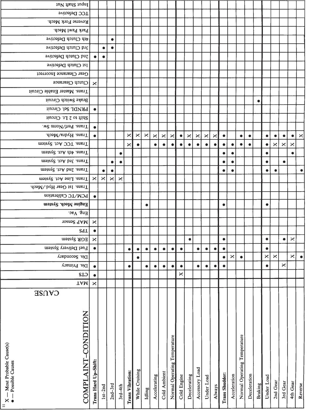
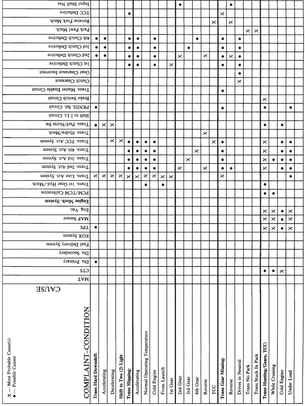
4 CLUTCH APPLICATION CHART GEAR R FWD/REV DOG CLUTCH To 2nd Driven Gear To 2nd Driven Gear To 2nd Driven Gear To 2nd Driven Gear To Reverse Driven Gear 1st CLUTCH ON ON ON ON 1st SPRAG ON 2nd/Reverse CLUTCH ON ON 3rd CLUTCH ON 4th CLUTCH ON TCC ON* ON ON ON * 1993 and up only Figure 2 4
5 MECHANICAL: The general design of the Saturn automatic transaxle is a parallel shaft arrangement where the entire transaxle is located in line and directly behind the engine. The transaxle provides four speeds forward and one reverse. Mounted on the main parallel shaft is the first clutch drum, the second/reverse clutch drum and the third clutch drum. Mounted on the counter parallel shaft is both the one-way clutch and fourth clutch drum. Separate from both the main and counter shafts is a Forward/Reverse Servo sliding dog clutch which engages either the second driven gear or the reverse driven gear on the counter shaft (See Figure 2). First Gear: When the transaxle is placed into the D4 position, the manual valve directs oil to apply the clutches in the first clutch drum locking the drive gear to the main shaft. The same oil that comes off of the manual valve to apply the first clutch is also directed to the Forward/Reverse servo to ensure that the dog clutch is locked down onto the second driven gear on the counter shaft. With the first clutch now applied locking the first drive gear to the main shaft, the one-way clutch holds locking the first driven gear to the countershaft. The main shaft drives the first drive gear in a clockwise direction. The first drive gear turns the driven gear on the countershaft in a counter clockwise direction. The counter shaft then turns the differential in a clockwise direction providing the transaxle with either a 2.24 or 2.53 first gear ratio, depending on year and make (Refer to the chart in figure 4 on page 7). Second Gear: At a predetermined point based on throttle position, vehicle speed and temperature, the PCM will command a shift into second gear by turning off the 2nd/Reverse actuator (Solenoid). When this occurs, oil pressure is sent to apply the clutches in the 2nd/Reverse clutch on the main shaft. This locks the 2nd/Reverse drive gear to the main shaft which causes a ratio change (1.17 or 1.56) freewheeling the one-way clutch (The first clutch drum remains applied but is ineffective with the one-way clutch freewheeling). Third Gear: When third gear takes place, the 2nd/reverse actuator is turned on exhausting the oil pressure from the second clutch. Simultaneously, the 3rd actuator is turned off allowing oil pressure to pass through the actuator and apply the clutches in the third clutch drum. With the third clutches applied, the third drive gear is locked to the main shaft driving the third General Description of Operation driven gear on the counter shaft. The result is a 2-3 shift with a third gear ratio of either a 0.81 or 1.03 to 1.0. Fourth Gear: The 3-4 shift operates exactly like the 2-3 shift. The 3rd actuator is turned on to exhaust pressure from the third clutch drum. Simultaneously the 4th actuator is turned off to apply the clutches in the fourth clutch drum. This causes a 3-4 shift to occur with a fourth gear ratio of either 0.60 or 0.70 to 1.0. Reverse Gear: When Reverse is selected, the manual valve directs oil pressure through the 2nd/reverse actuator to apply the clutches in the second/reverse clutch drum. This locks the 2nd/reverse drive gear to the main shaft. The manual valve also directs oil pressure to the forward/reverse servo dog clutch. This engages and locks the reverse driven gear to the counter shaft. The main shaft is driving the 2nd/reverse drive gear in a clockwise direction. The reverse part of the 2nd/reverse drive gear meshes with an idler gear in the case. The 2nd/reverse drive gear forces the idler gear to rotate counter clockwise. The idler gear also meshes with the reverse driven gear on the countershaft and forces it to move in a clockwise direction. The counter shaft the turns the differential in a counter clockwise direction providing a reverse gear ratio of 2.39 to 1.0. TCC Apply: The torque converter clutch is applied in 2nd, 3rd and 4th gears for 1991 and 1992 models and up vehicles have converter clutch apply in 1st, 2nd, 3rd and 4th gears. The speed at which the converter clutch will apply in 1st or 2nd gears is based on vehicle speed and tailored by throttle position, engine temperature and transaxle temperature. Once applied, the TCC will stay applied until vehicle speed is low enough in 2nd gear for the TCC to release. The TCC will also release when the brake pedal is depressed in 2nd gear at low engine speeds or when the transaxle downshifts into 1st gear. Cold Temperature Operation: Under cold operating conditions the high viscosity of the transmission fluid may result in the sluggish operation of the hydraulic and electrohydraulic operation of the transaxle. Because of this, when fluid temperatures reach below -13 C (9 F) the PCM will control the transaxle using only 1st and 3rd gears. Once the transaxle fluid temperature has reached - 12 C (10 F), the PCM will control the transaxle using the standard shift patterns. 5

6 Design Changes: Throughout this manual, there will be references between 1st and 2nd design. This refers to a change that was made during the 1992 model year. The 1st design parts apply to vehicles with a VIN prior to NZ and between VIN's NZ through NZ The 100 vehicles made between VIN NZ and NZ used 2nd design parts as a trial run. After VIN NZ they continued with 2nd design parts. This change was implemented to prohibit the movement of the Forward/Reverse servo piston toward reverse if the vehicle is traveling forward greater than 3 mph. The components that changed are: A STAMPED IDENTIFICATION CODE CAN BE FOUND IN THIS AREA 1. Case assembly. 2. FWD/REV servo piston and spring. 3. Valve body including the manual valve, spacer plate and gaskets. 4. PCM. These components are NOT interchangeable. Added Features: 1993 and up vehicles had added shift scheduling strategy changes for improved driveability. The features that were added are: 1. Uphill Feature - While traveling up certain grade hills, the transaxle will not upshift to a higher gear if that gear cannot maintain speed on the grade. Even if the driver completely lifts off the throttle, the transaxle will not upshift thus preventing unnecessary shifting. After reaching the top of the hill, the normal gear shift schedule will resume operation. 2. Downhill Feature - If traveling down steep grades, the PCM/TC (Powertrain Control Module - Transaxle Control) may automatically select a lower gear. This system assist engine braking, reduces transaxle shifting, and reduces braking required while going downhill. 3. Traction Control - Under certain slip conditions, the PCM/EC (Engine Control) may instruct the PCM/TC to do an upshift to help reduce slip. IDENTIFICATION CODE BREAKDOWN 1. Model Year (3 = 93) 2. Model Code: MP2 = Base Manual MP3 = Perf. Manual MP6 = Auto Base MP7 = Auto Perf. 3. Plant Code (1 = Spring Hill TN) 4. Julian Date Code (Feb. 12 = 043 day of the year) 5. Hour of Day: 0 = Midnight C = Noon A B AM D EF L MNC PM K G J I H 6. Change Code Digit (Increments 0-9) Figure 3 6

7 GEAR TEETH COUNTS AND RATIOS All SOHC engines use MP6 Transaxles All DOHC engines use MP7 Transaxles GEAR 1st Drive 1st Driven 2nd Drive 2nd Driven 3rd Drive 3rd Driven 4th Drive 4th Driven Rev Drive Rev Driven Rev Idler Final Drive Output Shaft st Design* MP6 Base nd Design** MP6 Base MP7 Performance ACTUATORS: The TAAT is equipped with 5 solenoids called actuators. These transaxle control actuators are electrohydraulic solenoid valves consisting of a housing, valvebody, sliding armature and a electromagnetic coil. They are a three port design with a pressure supply port, a pressure outlet or control pressure port, and an exhaust port (See Figure 5). The actuators have normally applied valves. When no voltage is applied to the terminals, a return spring holds the valve open and the actuator will allow oil to flow from the supply port to the outlet pressure port. When current flows through the coil, the magnetic field is energized pulling the sliding armature against the return spring. When the armature is in this position, the valve is closed, the pressure port is blocked, and the outlet port is connected to the exhaust port. These 5 actuators are located in the transaxle mounted on top of the valvebody (See Figure 6). Each actuator may be completely energized (closed), de-energized (open), or pulse width modulated (PWM). Figure 7 shows a basic solenoid application chart illustrating both closed, open and pulsed width modulated states. When an actuator is being modulated, the valve opens and closes up to 70 times per second. This allows a percentage of oil pressure available at the supply port to pass to the outlet port. The actual percentage time the actuator is pulsed, is determined by an electrically controlled duty cycle from the PCM. This is the ratio of the length of time the valve remains open (pulse width) to the total length of time of each cycle (one on and off cycle). Ring Gear GEAR 1st Gear 2nd Gear GEAR RATIO EXHAUST PORT 3rd Gear th Gear Reverse PRESSURE OUTLET PORT Final Drive * Vehicles built prior to, and including VIN PZ ** Vehicles built after, and including VIN PZ NOTE: An updated ratio chart can be found on page 114 Figure 4 Figure 5 PRESSURE SUPPLY PORT 7


8 3rd Actuator Line Pressure Actuator 2nd Actuator TCC Actuator 4th Actuator Actuator Identification and Location Figure 6 Figure 8 Connector Plate GEAR 1st ACTUATORS LINE 2nd/REVERSE 3rd 4th TCC On/PWM ON ON ON OFF K J H G F 2nd 3rd On/PWM OFF ON ON On/PWM On/PWM ON OFF ON On/PWM FRONT OF VEHICLE 4th On/PWM ON ON OFF On/PWM Reverse On/PWM OFF ON ON OFF Actuator Apply Chart Figure 7 A connector plate snaps onto the actuator pins with a 10 pin connector that comes through the top pan on the transaxle (See Figure 8). Each of the actuators can be checked for resistance with a DVOM through the 10 pin connector. Refer to Figure 9 for All 1991 and 1992 actuators measure approximately 2.5 to 4.5 ohms while all 1993 and up actuators measure 4.0 to 6.0 ohms. An actuator resistance chart illustrated in Figure 10 provides the acceptable resistance tolerances based on temperature. These values may vary slightly, however, all actuators should be within 1 ohm of each other. IMPORTANT: These actuators will not interchange. Even though each actuator may have its own 7.5A fuse in the Underhood Junction Box shown in Figure 11, the 2nd 3rd 4th TCC Line E D C B A Actuator Terminal + Terminal - J A C E G Figure 9 PCM will recognize the ohm variation of the actuator and possibly cause DTC's (Diagnostic Trouble Codes) or Flag Codes. Always measure the resistance of the actuator to insure their proper application. Saturn color coded the actuators as well to assist in preventing the installation of the wrong actuators. BLACK and BLUE Actuators are used in 1991 and 1992 vehicles and up use H B D K F 8

9 ACTUATORS CONTINUED: RED Actuators. At the time of this printing, the part number for the 1991 and 1992 actuator is and up actuators are under the part number There is also no color on the top of the Actuator. This change took place in sometime in Refer to page 109. Temperature 2nd/Rev TCC Resistance (Ohms) Degrees F Degrees C & up Figure BA Data Link Connector Figure 12 GEAR SELECTION ACTUATOR 3rd LP 4th 2 3 2nd Actuator 3rd Actuator A/T Relay D R 4th Actuator TCC Actuator Underhood Junction Block Figure 11 AUDIBLE QUICK CHECK: An Audible quick check of the actuators can be easily performed to determine if the electrical system from the PCM to the actuator is in good working order. The proper procedure in the performance of this test is to first verify with a scanner that the Selector Lever Switch is working correctly. In other words, when you are in Park the scanner shows the letter P and so on. The next step, for models, is to remove the scanner from the Data Link Connector and jump terminal A to B in the connector as shown in Figure 12. After the terminals have been jumped, turn the ignition to the "ON" position. Do not start the engine. Next, move the selector lever into the manual 2 position and listen for a buzzing noise coming from the 2nd actuator. Use the chart in Figure 13 which illustrates the gear selector position to check the desired actuator. N Figure 13 Line Actuator When the gear selector is moved to the corresponding position, the PCM will pulse width modulate (PWM) the actuator at a set duty cycle for about six seconds. Listen and compare the noise of the suspected bad actuator to that of the other actuators. They should all be similar. If the noise coming from the suspected bad actuator is faint or not present, replace the actuator. IMPORTANT: Prior to replacing any actuator, check all connections at the actuator and connector plate. NOTE: Jumping terminals A and B will work on models only. Most scanners have the ability to perform an actuator test where each actuator can be cycled on and off. If your scanner has this option, it is not necessary to jump the DLC connector as just explained. 9
. 3. Attach a 300lb pressure gauge to the same port (See Figure 15). 4.")
10 LINE PRESSURE CHECK: The temperature sensor port doubles as a line pressure test port on the Saturn transaxle. Perform the following procedure: 1. Bring the transaxle temperature above 70 C (158 F). 2. Remove the temperature sensor from the case (See Figure 14). 3. Attach a 300lb pressure gauge to the same port (See Figure 15). 4. With the selector lever in Park, start the engine and let it run at idle (approximately 750 rpm's). Line pressure should be kPa (58-72 psi). 5. Remove the fuse for the line pressure solenoid (See Figure 11 on page 9 for fuse location). 6. With the engine idling in Park (approximately 750 rpm's), line pressure should be kPa ( psi). 7. Apply the parking brake and place the selector lever in the Drive position. 8. With the engine idling at 750 rpm's, pressure should be greater than 1200kPa (175 psi). NOTE: The high values shown above may be slightly lower if the transaxle temperature is greater than 110 C (230 F). However, if the pressure readings that have been obtained are substantially lower than the values provided above, the pump, pressure regulator and/or line pressure actuator may be faulty. TEMPERATURE SENSOR Figure 14 Figure 15 After the line pressure test has been completed, remove the pressure gauge from the pressure port. Before installing the temperature sensor, clean the threads on the sensor and R wrap fresh Teflon tape onto the threads. Once the temperature sensor has been installed and the connector plugged back in, clear diagnostic codes and/or information flags caused by having the sensor disconnected. SCANNER CHECK: Most scanners will provide a PRESSURE COMMAND LINE which is a calculated value. It could also be thought of as the "DESIRED" pressure inside the transaxle based on the command provided by the PCM. This Pressure Command Line value in the scanner can be compared to the actual working pressure inside the transaxle with a pressure gauge. There are some scanners that have a special test option which after the test was chosen, would automatically increase engine speed to 1500 rpm's. The scanner would then command line pressure to increase in steps starting at kpa ( psi) in 100 kpa (15 psi) intervals. This command provided by the scanner would also need to be compared to the actual working pressure through a pressure gauge. However, as previously stated, not all scanners have this special test option. An alternative would be to view the pressure command line on the scanner and step into the throttle and compare the "DESIRED" psi to the actual working pressure. Use the chart in Figure 16 for the comparitive command and gauge readings. 10
11 COMMAND LINE PRESSURE "DESIRED" PRESSURE GAUGE READINGS "ACTUAL" DIAGNOSTIC INFORMATION: VISUAL/PHYSICAL UNDERHOOD INSPECTION A careful visual and physical underhood inspection must be performed as part of any diagnostic procedure or in finding the cause of a failure. This can often lead to fixing a problem without further steps. Inspect wiring, fluid, cables and linkage. Inspect all the wires in the engine compartment for proper connections, burned or chafed spots, pinched wires, or contact with sharp edges or hot exhaust manifolds. This visual/physical inspection is very important. It must be done carefully and thoroughly. DIAGNOSTIC TROUBLE CODES Diagnostic trouble codes or information flags are two digit numbers that can range from 11 to 99. When a malfunction (MALF) is detected by the PCM, a diagnostic trouble code or information flag is set and the malfunction indicator lamp (MIL) telltale lamp may be illuminated. Diagnostic Trouble Code (DTC): Suspected failure detected. in the engine or transaxle will turn on MIL lamp when failure is present. Information flag: A diagnostic aid used when a minor malfunction. or intermittent problem occurs. It does not necessarily indicate a failure. Figure 16 MALFUNCTION INDICATOR LAMP This telltale lamp (SERVICE ENGINE SOON telltale lamp) is in the instrument cluster and has the following functions:. It informs the driver that a problem has occurred and that the vehicle should be taken for service as soon as reasonably possible.. It displays diagnostic trouble codes and/or information flags stored by the PCM which help the technician diagnose system problems.. It indicates "Open Loop" or "Closed Loop" engine operation. As a bulb and system check, the lamp will come on with the key On and the engine not running. When the engine is started, the lamp will turn off. If the lamp remains on, the self-diagnostic system has detected a problem. If the problem goes away, the lamp will go out in most cases after 10 seconds, but a diagnostic trouble code will remain stored in the PCM. When the lamp remains on while the engine is running, or when a malfunction is suspected due to a driveability problem, code retrieval must be performed. All engine codes, diagnosis and repairs should be dealt with first before attempting to move onto the transaxle codes and information flags. 11
12 TRANSAXLE SHIFT TO D2 TELLTALE LAMP ( VEHICLES) When a transaxle malfunction is detected, the malfunction indicator lamp (MIL) telltale lamp may illuminate. The telltale lamp will illuminate for all diagnostic trouble codes, but will not illuminate for information flags. A DTC 12 will flash followed by any engine diagnostic trouble codes that may be present, then a DTC 11 will follow. After DTC 11 is flashed three times, the SHIFT TO D2 telltale lamp will flash stored diagnostic trouble codes. If an information flag in the transaxle is stored along with diagnostic trouble codes, they will also be flashed at the same time. If only information flags are stored and a diagnostic check is completed, DTC 12 will flash followed by any engine diagnostic trouble codes, no DTC 11 will be flashed, but the SHIFT TO D2 telltale lamp will begin to flash transaxle flags. Automatic transaxle flags will not turn on the MIL lamp and are used as diagnostic aids. If a faulty Shift to D2 telltale bulb or circuit is suspected, it can be checked with some scanners by selecting the TCM menu. DTC 26 may also be logged if the Shift to D2 lamp circuit has a fault. LOW COOLANT/HOT LAMP (1993 AND 1994 VEHICLES) For 1993 and 1994, the SHIFT TO D2 lamp has been eliminated. The low coolant hot lamp will flash diagnostic trouble codes or information flags the same way as described above under the heading TRANSAXLE SHIFT TO D2 TELLTALE LAMP. INTERMITTENT MALFUNCTION INDICATOR LAMP (MIL) TELLTALE LAMP In the case of an intermittent problem, the MIL telltale lamp will illuminate for 10 seconds and then will go out. However, the corresponding diagnostic trouble code and any information flags set by the problem will be stored in the memory of the PCM until removed. READING DIAGNOSTIC TROUBLE CODES The provision for communicating with the PCM is the data link connector (DLC) which is located under the instrument panel (See Figure 17). The diagnostic trouble code(s) or information flag(s) stored in the PCM's memory can be read either through a hand-held diagnostic scanner plugged in the data link connector or by grounding the diagnostic terminal in the data link connector. Once terminal B (The Diagnostic Terminal) is connected to terminal A (The Internal PCM Ground) BA Data Link Connector Figure 17 as shown in Figure 17 above, the ignition switch must be moved to the ON position, with the engine not running. At this point, the MIL telltale lamp should flash a Diagnostic Trouble Code (DTC) 12 three times consecutively (Remember, the MIL telltale lamp is for PCM (EC) diagnostic trouble codes or SHIFT TO D2 lamp on 1991 and 1992 vehicles. The LOW COOLANT/HOT lamp is used on 1993 and 1994 vehicles for PCM (TC) diagnostic trouble codes). The flash sequence would be as follows: Flash, pause, flash-flash, long pause, flash, pause, flash-flash, long pause, flash, pause, flash-flash. DTC 12 indicates that the PCM's diagnostic system is operating. If DTC 12 is not indicated, a problem is present within the diagnostic system itself. After the output of DTC 12, the MIL telltale lamp will indicate any engine diagnostic trouble code three times if any are present, or it will simply continue to output DTC 12. If more than one diagnostic trouble code has been stored in the PCM's memory, the diagnostic trouble codes will be displayed from the lowest to the highest, with the exception of DTC 11 which indicates transaxle diagnostic trouble codes. DTC 11 will always flash last, followed by the Shift to D2 telltale lamp or the low coolant/hot telltale lamp which will flash transaxle diagnostic trouble codes. Each diagnostic trouble code will be displayed three times. CLEARING DIAGNOSTIC TROUBLE CODES When a diagnostic trouble code and/or information flag is set, the PCM stores it in two tables: The General Information and Malfunction (MALF) History. When 12
13 CLEARING CODES CONTINUED: clearing diagnostic trouble codes or information flags from General Information WITHOUT a scan tool, you will need to have the ignition ON and ground the data link terminals A to B three times within five seconds. General Information can also be cleared with 50 ignition ON cycles. Malfunction history can be cleared ONLY with a Scan tool. NOTE: Disconnecting power to the PCM has no effect on stored diagnostic trouble codes or information flags in Malfunction history, but may clear diagnostic trouble codes and/or information flags in General Information. FIELD SERVICE MODE If the diagnostic terminal is grounded with the engine running, the system will enter the Field Service Mode. In this mode, the MIL telltale lamp will indicate whether the system is in open loop or closed loop. In open loop the MIL telltale lamp flashes two and one-half times per second. In closed loop, the lamp flashes once per second. Also, in closed loop, the telltale lamp will stay off most of the time if the system is running lean. It will stay on most of the time if the system is running rich. While the system is in the Field Service Mode and the closed loop timer is bypassed, new diagnostic trouble codes cannot be stored, but information flags can be stored in the PCM. PCM LEARNING ABILITY The PCM/EC has a "learning" ability which allows it to make corrections for minor variations in the fuel system to improve driveability. If the battery is disconnected, the learning process resets and begins again. A change may be noted in the vehicle's performance. To "teach" the vehicle, make sure that the engine is at operating temperature. The vehicle should be driven at part throttle, with moderate acceleration and idle conditions until normal performance returns. To relearn idle the engine should be idled in D (Drive) with the vehicle at operating temperature until idle stabilizes. The TC portion of the PCM also has a learning ability to achieve smooth shifts. If the battery is disconnected, the TCM will loose the fine tuning of shift points, which has been learned while driving the vehicle. Disconnecting the battery will not reset the TCM adaptive parameters. The adaptives can only be reset using the service stall system (SSS). To relearn the shifts, the vehicle should be driven so that each shift is achieved at least twice. RESETTING ADAPTIVE PARAMETERS Because the PCM/TC has the ability to adapt to various transaxle conditions, it is necessary to reset the adaptive parameters after certain repairs have been performed. The adaptives can be reset using the service stall system (SSS). The adaptives should only be reset after the following repairs have been made:.. Replacing a transaxle. Replacing a line pressure actuator. Transaxle overhaul when new clutch plates are installed. Replacing a valvebody. Replacing the PCM for a transaxle related failure. After performing a repair, the vehicle must be driven to allow the adaptives to learn new shift times and pressures before returning the vehicle to a customer. Refer to Learn-in procedure below. LEARN-IN PROCEDURE If one of the repairs mentioned has been performed, then the adaptives should be reset using the SSS. Also, the vehicle must be driven, preferably on a highway, according to the following steps. By following these steps, the adaptives will be properly learned prior to returning the vehicle to the customer. 1. Place shift mode switch in the normal mode position. 2. Warm up transaxle (oil temp. above 45 C [113 F]). 3. Perform 10 sets of upshift (1-2, 2-3, 3-4) at 30% throttle: DOHC (LLO) Engine 1. While coasting at 56 km/h (35 mph) slowly accelerate to half throttle to achieve a 4-3 downshift. 2. With selector in D3 while coasting at 32 km/h (20 mph) slowly accelerate to 75% throttle to achieve a 3-2 downshift. Repeat both procedures five times. SOHC (LKO) Engine 1. While coasting at 64 km/h (40 mph) slowly accelerate to half throttle to achieve a 4-3 downshift. 2. With selector in D3 while coasting at 48 km/h (30 mph) slowly accelerate to one half throttle to achieve a 3-2 downshift. Repeat both procedures five times. 13
14 AUTOMATIC TRANSAXLE ADAPTIVE DISABLES The following conditions cause adaptives to be disabled. Oil temperature disable (trans oil temperature less than 28 C [82 F] or trans oil temperature greater than 140 C [284 F]). TP sensor movement during shift. Movement greater than 8% at beginning of shift. Non-adaptable shift. a. Downshift to first gear. b. Garage shifts. Serial data loss (active DTC 51 - DTC does not have to be set). Low ignition voltage (ignition voltage less than 11.5 volts). SHIFT TO D2 LAMP ( ) The Shift to D2 indicator lamp is lit when any of the following conditions exist: Any time serial communications to TCM are being run. Scan tool connected or the diagnostic terminal is grounded. The engine running and the system is failed at low line. The engine is running and all gears above 1st (2nd, 3rd and 4th) are lost in Drive. The engine is running and the master enable relay is turned off for any reason other than hot conditions and the vehicle speed is less than 25 KPH (15 MPH).These include: a. High ignition voltage. b. Low ignition voltage. c. Master relay failed open. d. Master Relay Shorted Across Coil. e. Serial communications failure. The engine is running and 3rd or 4th gears are stuck on and the vehicle speed is less than 25 KPH (15 MPH). The engine is running and TCC is stuck on and first gear is unattainable with turbine speed less than 700 RPM. The ECM will light the Shift - to - D2 light when it loses communications with the TCM (ECM Code 82). TCC PARAMETERS Engine temperature above 50 C (122 F). Transaxle temperature above a given value in relation to intake air temperature (IAT) sensor valve. a. TCC on if IAT value is less than -14 C (7 F)and transaxle temperature is greater than +20 C (68 F). b. TCC on if IAT value is greater than 10 C (50 F) and transaxle temperature is greater than +10 C (50 F). c. TCC on for the IAT range between -14 C (7 F) and +10 C (50 F) uses a calculated transaxle oil temperature required to allow TCC. Above 20% No throttle, TCC on in 2nd gear. Below 20% No throttle, TCC on in 3rd gear. Low engine speed downshift (i.e., light throttle or steady) throttle with load increase. Low end of 3rd gear speed range, brake on = TCC off. TCC off on all coast downshifts. Fast decel; i.e., brake lock on ice = TCC off, gear = neutral. On 1993 vehicles the TCC may be commanded on at high throttle openings in 1st gear. NUMBER CODE DESCRIPTION CODE/FLAG Line Pressure High ( Vehicles)* Line Pressure High (1991 Vehicles)* Line pressure Low ( Vehicles)* Line Pressure Low ( Vehicles)* Hot Lamp Illuminated No 1st Gear No Gears Available ( Vehicles)* No Gears Available ( Vehicles)* 2nd Gear Stuck On * Diagnostic Procedure is the same for both Codes and Flags Note: Refer to page 105 for 1996 and Up Trouble Codes Figure 18 Code Flag Code Flag Flag Code Code Flag Code 14
15 NUMBER DESCRIPTION CODE/FLAG Technical Service Information TROUBLE CODES/INFORMATION FLAGS Continued No 2nd Gear No 3rd Gear No 4th Gear No TCC TCC Stuck On Transaxle Temp. Circuit Open (Cold) Transaxle Temp. Circuit Grounded (Hot) ECM Communications Failed (1991 Perf. [LLO], Vehicles) No Turbine Speed Signal Turbine Speed Sensor Signal Noise No Vehicle Speed Signal Vehicle Speed Sensor Signal Noise Actuators Lost Power (1994) Master Enable Relay Open/Grounded (1993 Vehicles) Master Enable Relay Open/Grounded ( Vehicles) Master Enable Relay Shorted to Voltage (1993 Vehicles) Master Enable Relay Shorted to Voltage ( Vehicles) Selector Switch - No Data Selector Switch - Undefined Data PCM Communication Interrupt Failure Hold Mode Voltage Low ( Vehicles) Selector Switch - Invalid Data (1991 Perf. [LLO], Vehicles PCM Serial Link Data Invalid Hold Mode Stuck On ( Vehicles) Hold Mode Stuck Off ( Vehicles) A/D Error - Analog Voltage Signals Converted to Digital Signals inside the PCM Transaxle Temperature Resistor Failure Generic Field Effect Transistor (FET) Driver Failure (93-94)* Generic FET Driver Failure (1991 and 1992 Vehicles)* Non-Volatile Random Access Memory (RAM) Failure PCM Programmable Read-Only Memory (PROM) Failure PCM Interrupt Failure PCM Random Access Memory (RAM) Failure * Diagnostic Procedure is the same for both Codes and Flags Note: Refer to page 105 for 1996 and Up Trouble Codes Figure 19 Code Code Code Code Code Code Code Code Code Code Code Code Code Code Flag Code Flag Code Code Flag Code Code Flag Code Code Code Code Code Flag Flag Flag Flag Flag 15
16 NUMBER DESCRIPTION CODE/FLAG Technical Service Information TROUBLE CODES/INFORMATION FLAGS Continued PCM Electrically Erasable/Programmable Read-Only Memory (EEPROM) Failure Battery Voltage Out of Range High or Low Clamp Circuit Shorted ( Vehicles) Clamp Circuit Open ( Vehicles) Line Pressure Actuator Circuit Grounded/Open Line Pressure Actuator Circuit Shorted to Voltage 2nd Gear Actuator Circuit Grounded/Open 2nd Gear Actuator Circuit Shorted to Voltage 3rd Gear Actuator Circuit Grounded/Open 3rd Gear Actuator Circuit Shorted to Voltage 3rd Gear Stuck On ( Vehicles)* 3rd Gear Stuck On ( Vehicles)* 4th Gear Actuator Circuit Grounded/Open 4th Gear Actuator Circuit Shorted to Voltage 4th Gear Stuck On ( Vehicles)* 4th Gear Stuck On ( Vehicles)* TCC Actuator Circuit Grounded/Open TCC Actuator Circuit Shorted to Voltage Temperature Signal Unstable (1991 Base [LKO] Vehicles) Temperature Signal Low Brake Switch Stuck Open Brake Switch Stuck Closed Engine Speed Signal Invalid TCC Hold Circuit Grounded/Open ( Vehicles) TCC Hold Circuit Shorted to Voltage ( Vehicles) Master Enable Relay Stuck On ( Vehicles) Master Enable Relay Stuck On ( Vehicles) DLC Serial Communication Link Interrupt (1991 Base [LKO] Vehicles) Clamp Circuit Intermittent Fault ( Vehicles) Master Enable Circuit Intermittent Fault ( Vehicles) Line Pressure Actuator Circuit Intermittent Fault TCC Actuator Circuit Intermittent Fault 2nd Gear Actuator Circuit Intermittent Fault 3rd Gear Actuator Circuit Intermittent Fault 4th Gear Actuator Circuit Intermittent Fault * Diagnostic Procedure is the same for both Codes and Flags Note: Refer to page 105 for 1996 and Up Trouble Codes Figure Flag Flag Flag Flag Flag Flag Flag Flag Flag Flag Code Flag Flag Flag Code Flag Flag Flag Flag Flag Flag Flag Flag Flag Flag Flag Flag Flag Flag Flag Flag Flag Flag Flag Flag

17 THE PCM WIRING IDENTIFICATION The Powertrain Control Module (PCM) is partitioned to control both the engine and transaxle management. When the engine side of the PCM is discussed, it is often referred to as PCM/EC for Engine Control. When the transaxle side of the PCM is discussed, it is often referred to as PCM/TC for Transaxle Control. This PCM is located behind the left hand side of the dash as shown in Figure 21. The PCM has 3 electrical connectors plugging into it as shown in Figure 22. They are referred to as the J1, J2 and J3 connectors. The J1 and J2 connectors primarily handle the engine related electrical inputs and outputs. The J3 connector contains most of the transaxle inputs and outputs. The J1 connector has 2 rows of pins with 16 pins in each row. One row is labeled "C" while the other row is labeled "D" (See Figure 23). The connector is BROWN in color for 1991 to 1992 TBI vehicles and BLUE for MFI vehicles and up the connector color went to PINK on TBI vehicles and LIGHT BLUE on MFI vehicles. The J2 connector also has 2 rows of pins but with 12 pins in each row. One row is labeled "A" while the other row is labeled "B" (See Figure 24). The color code of the J2 connector is the same as the J1 connector for the exception of 1991 and 1992 MFI vehicles, it will be BLACK in color. Even though the J1 and J2 connectors may be the same in color in most vehicles, they can be easily distinguished since one has a total of 32 pins and the other having 24 pins. J1 J2 J3 Figure 22 The J3 connector is also a 32 pin connector with 2 rows of 16 pins. One row is labeled "E" while the other row is labeled "F" (See Figure 25). This connector is GREEN in color for all models and years. Starting on page 21 beginning with Figure 26 are illustrations of the J3 Connector wiring diagrams for transaxle related inputs and ATSG MANUALS AND BULLETINS NOW AVAILABLE ON CD-ROM Call (800) For Details PCM Figure 21 17
18 J1 Connector Pinout Note: Connector shown above is for models up to and including 1994 Figure 23 18
19 J2 Connector Pinout Note: Connector shown above is for models up to and including 1994 Figure 24 19
20 J3 Connector Pinout Note: Connector shown above is for models up to and including 1994 Figure 25 20


21 * PCM MLP ACTUATOR GROUND 4TH ACTUATOR GROUND 3RD ACTUATOR GROUND 2ND/REV ACT. GROUND TCC ACTUATOR GROUND CLAMP HLD ACT ONLY TRANS ENABLE RELAY GROUND ONLY J3 CONNECTOR E E F F Technical Service Information PCM/Actuators Wiring Diagram Terminal numbers in J3 Connector on PCM F1 E10 F3 F2 E14 E13 E12 F D B H K TRANSAXLE ACTUATORS MLP ACTUATOR 4TH ACTUATOR 3RD ACTUATOR 2ND/REV ACTUATOR TCC ACTUATOR G C A J E Terminal Letters Stamped on Connector Plate in VB TRANSAXLE/ACTUATOR ELECTRICAL CONNECTOR K J H G F E D C B A TCC UNDERHOOD JUNCTION BOX 7.5 A FUSES MLP 4TH 3RD 2ND TCC HLD TRANS MASTER ENABLE RELAY HLD* 2nd Battery Power Ignition Power UNDERHOOD JUNCTION BOX Trans Master Enable Relay * CLAMP TRANS HOLD ACTUATORS: On 1991 and 1992 vehicles, the amount of current required to energize an actuator is greater than the amount of current required to HOLD an actuator in the closed position. Hold Mode is a feature built into the PCM that reduces current draw of the 2nd, 3rd, and 4th actuators when these clutches are being held off. Figure Fuse panel shown is for vehicles up to th LP 3rd


22 Pattern Select Switch/TFT/TSS Wiring Diagram PCM J3 Connector J3 Connector E1 E2 TCC-A TCC HOLD CIRCUIT* TCC-B 12V 12V 12V 12V PWR GND PWR GND TEMP. + F14 E11 E8 E7 E6 E9 F4 *5 ohm Wire BLK/WHT YELLOW GREY WHITE TAN/WHT PATTERN SELECT SWITCH A B C D TRANS. FLUID TEMP. SENSOR A TEMP - F15 ORN/BLK B Schematic shown is for vehicles up to 1994 TSS + E15 GRY/RED TURBINE SPEED SENSOR A TSS - E16 DK BLU/WHT B J3 CONNECTOR E E F F PATTERN SELECT SWITCH D C B A A TAN/WHT TRANS. FLUID TEMP./ TURBINE SHAFT SENSOR B ORN/BLK TFT A GRY/RED TSS B DK BLU/WHT Figure 27 22
 is a 1991 and 1992 model year feature only.")
23 Vehicle Speed Sensor Wiring Diagram PCM VSS HI J2 Connector A9 YELLOW VEHICLE SPEED SENSOR A VSS LOW A10 PURPLE B Schematic shown is for vehicles up to 1994 J2 CONNECTOR B A A VSS B Figure 28 *TCC HOLD CIRCUIT The TCC Hold Circuit shown in Figure 27 (*5 ohm wire circuit) is a 1991 and 1992 model year feature only. The amount of electrical current required to energize an actuator is greater than the amount required to hold an actuator in position. The Hold Mode is a feature built into the PCM that reduces current draw of the TCC actuator when TCC is being held on. After TCC is applied a driver built into the PCM is opened and an actuator ground path is provided inside the PCM through the 5 ohm resistance wire. CONT. PATTERN SELECT SWITCH To adjust the Pattern Select Switch, put the selector lever in the D4 position. Do not start the vehicle. Place an ohm meter onto the Pattern Select Switch as shown in Figure 29 (The terminal contacts to be used is in connector 1 shown in Figure 27 on page 22). Rotate the switch until the ohm meter reads continuity. Once adjusted, secure the Pattern Select Switch. Figure 29 23
24 PATTERN SELECT SWITCH CONTINUED: After the Pattern Select Switch has been adjusted, the gear selection can be viewed through a hand held scanner to ensure that the proper signal is being sent to the PCM. If the scanner reveals that the switch is sending an incorrect signal after an adjustment, a check can be made on the switch to determine if the switch is defective or the wiring is defective. Figure 30 below shows a view of a 6 pin connector on the switch where the check is to be made. The bottom pin is terminal A, the next one up is terminal B then C, D, E and F. These letters are molded into the connector along side each of the pins for easy identification. Figure 31 illustrates which pins are suppose to be GROUNDED in P, R, N, D4, D3 and D2. With the switch mounted to the transaxle, place the negative lead of the ohm meter to a good known ground. Place the positive lead onto terminal A. There should be continuity in P, R and D2 only. Repeat the same procedure for each pin utilizing the chart in Figure 31 to determine proper grounding sequence. TRANSAXLE FLUID TEMP. SENSOR The transaxle fluid temperature sensor (TFT) monitors fluid temperature by using a thermistor (sensor) located in the transaxle pressure port near the external filter. The sensor resistance will increase as temperature decreases and decreases as the temperature increases. The PCM supplies a 5 volt signal through the Tan/White wire to terminal A on the sensor and monitors the voltage return on the Orange/Black wire coming out of terminal B. As the resistance goes up, the voltage goes down, as the resistance goes down, the voltage return goes up. The voltage value on the return signal line is converted to a temperature value in the PCM. Most hand held scanners can view the temperature values. If the sensor fails, or the wiring circuit should short or open, a DTC 31 or 32 could appear. To check the operation of the temperature sensor, unplug the sensor. Place the positive lead to terminal A and the negative lead to terminal B (See Figure 32). Use the chart illustrated in Figure 32 for the temperature values and the corresponding resistance. D A TAN/WHT B ORN/BLK Gear Select P R N D4 D3 D2 C B A A B C D X X X X X X X X X X X X X = Pin Grounded Figure 31 C F RESISTANCE Figure
25 TURBINE SPEED SENSOR The Turbine Speed Sensor (TSS) is a permanent magnet (PM) generator mounted near the pressure filter on the transaxle case (See Figure 27). The PM generator produces a pulsing voltage (AC) whenever turbine shaft speed is above 250 rpm. These pulses occur eight times per each turbine shaft revolution and is converted to an RPM signal inside the PCM. These pulses can be viewed with a DVOM set to Hz. If a DVOM is set on AC volts, voltage would increase with speed. If this sensor is checked with an ohm setting, the resistance value should be between 800 to 1600 ohms. The Turbine RPM signal can also be checked and viewed through a hand held scanner. VEHICLE SPEED SENSOR The Vehicle Speed Sensor (VSS) is located on the transaxle case by the differential (See Figure 28). This sensor is also a also a PM generator which produces a pulsing voltage (AC) whenever the vehicle speed is above 5 km/h (3 mph). These pulses occur sixteen times per each revolution of the differential housing and is converted to provide vehicle speed in miles per hour inside the PCM. These pulses can be viewed with a DVOM set to Hz. If a DVOM is set on AC volts, voltage would increase with speed. If this sensor is checked with an ohm setting, the resistance value should be between 800 to 1600 ohms. The Vehicle Speed signal can also be checked and viewed through a hand held scanner. BRAKE SWITCH The Brake Switch contains 2 four pin connectors as shown in Figure 33. Terminal "B" in connector 1 receives battery voltage from the Ignition Run circuit. When the brake is released, this battery voltage is allowed to travel through the switch and out terminal "C" in connector 2. This battery voltage is then sent to the PCM in connector J3 terminal E5 (See Figure 25 on page 20). If the transaxle is in 2nd gear and engine speed is low, and the brake switch opens signalling the PCM that the brakes are applied, the PCM unlocks the converter. For 1993 and up this switch helps determine if a downshift should occur while going down hill. The switch can be checked with an ohm meter by placing meter leads across terminal B in connector 1 and terminal C in connector 2. Continuity should be seen with the brake released and go to open as soon as the brake is applied. Battery Voltage A B C D Connector 1 Connector 2 A B C D Brake Switch Figure 33 THROTTLE POSITION SENSOR The Throttle Position Sensor (TPS) is a variable resistor that is connected to a 5 volt reference source, a ground, and an input signal at the PCM (See Figure 34). When the throttle blade is closed, the sensor input voltage will be low and increase as the throttle is opened. The TPS is mounted on the throttle body facing the firewall and is connected to the throttle shaft which is controlled by accelerator movement. If a suspected malfunction occurs, DTC's 21 and 22 will be stored in the Engine side of the PCM. To check the TPS, carefully back probe terminal "B" with the negative lead of a volt meter set to DC volts. With the positive lead, carefully back probe terminal "C" (See Figure 34). Turn the ignition on without starting the engine. At closed throttle, approximately 0.5 volts should be seen. As the throttle increases, the voltage should rise smoothly and proportionally. When wide open throttle is reached, approximately 4.5 volts should be seen. TPS A C B A = Gray C = Dk Blue B = Black J2-B5 J2-A8 J1-D3 TPS Connector View Figure 34 Signal wire to Connector J3 pin E5 PCM 5V REF Signal Voltage Ground 25
26 ENGINE COOLANT TEMP. SENSOR The Engine Coolant Temperature Sensor (ECT) is a thermistor located in the lower coolant passage of the engine's cylinder head under the EGR valve. When coolant temperature is cold the sensor has a high resistance, as the temperature increases the resistance of the sensor decreases. The PCM (Connector J1 terminal C12) provides a 5 volt signal to the coolant sensor (Terminal A). The wire coming from terminal B at the sensor is internally grounded in the PCM at connector J1 terminal C3 (See Figure 35). The PCM reads the voltage drop on the signal line which is calculated and translated to determine engine coolant temperature. ECT A B J1-C12 J1-C3 Figure 35 PCM 5V REF Signal Wire This ECT sensor circuit could produce DTC's 14, 15 or 17 depending upon the type of failure. If the ECT sends a temperature reading higher than 140 C (284 F) and the engine has only been running just a little over 10 seconds, a DTC 14 would appear. If the engine has been running longer than 5 minutes and the temperature remains below - 35 C (-31 F), a DTC 15 will appear. A DTC 17 will set if the pull-up resistor inside the PCM switches and there is no change in the coolant temperatures signal. The resistance check chart shown in Figure 36 provides approximate ohms values based on temperature. NOTE: It is near impossible to check the resistance of this sensor while its still in the car. The entrance hole to the two pins contained in the sensor is only a ¼ inch in diameter and the pins are small, delicate and close together. It is highly recommended that a hand held scanner be used to check coolant temperature during any diagnosis. The following is an example of diagnosing the temperature sensor with a scanner: 1) DTC 14 = If a high temperature reading exists at all times, unplug the connector and view the scanner to see if the reading went below -35 C (-32 F). If it did, the ECT is bad. If it didn't, either the wiring is shorted to ground or the PCM is bad. 2) DTC 15 = If the temperature reading remains low, unplug the temperature sensor and cross the two terminals in the connector with a suitable jumper. View the scanner to see if the temperature now reads above 130 C (266 F). If it did, either the sensor is bad, or the pin cavities are not making a tight fit onto the pins. If it didn't, either there is an open in the wiring, or the PCM is bad. 3) DTC 17 = PCM is bad. IMPORTANT: The pins in the sensor can be easily bent when plugging the connector back on. Be very careful as the alignment slots alone do not guide the connector onto the pins properly. The part number for the ECT sensor at the time of printing is C F RESISTANCE A YELLOW Figure 36 B BLACK

27 SHIFT MODE SELECTOR SWITCH The Shift Mode Selector Switch allows the operator to select a Normal or Performance (aggressive) shift schedule. The switch is mounted on the console near the selector lever. Initial shifts after a cold start are completed in the Normal mode even if the Performance is selected. Performance shift schedule timing and pressures are based on learned Normal mode shift characteristics. The Norm/Perf switch is a simple On/Off switch. The signal to the PCM (Connector J3 Terminal E3) is pulled up to 12 volts by the PCM when the Norm/Perf switch is open indicating that the Normal mode has been selected (See Figure 37). When the Performance mode is selected, the PCM circuit will be pulled to ground. This voltage drop indicates to the PCM that the Performance mode has been selected by the operator. When the switch is placed back into the Normal mode, the circuit is opened and the PCM pin will be back to battery voltage and once again indicate that the Normal range has been selected. The Light Emitting Diode (LED) shown in Figure 37 illuminates when the Performance mode is selected due to the switch being closed completing a circuit from terminal C to B. Power is turned on at terminal A whenever the Courtesy light or Head lights are turned on. This circuit completes to ground at terminal B causing the bulb to illuminate the words Norm/Perf on the face of the switch. If a malfunction occurs in the Norm/Perf electrical circuit, the operation of the switch can be easily checked with the use of a DVOM in the following manner: 1) Set the meter to ohms. 2) Place the positive lead to terminal A (See Figure 38). 3) Place the negative lead to terminal B. Approximately 17.5 ohms should be seen. 4) Place the switch into the Performance mode. 5) With the positive lead of the meter still on terminal A, place the negative lead onto terminal D. Approximately 17.5 ohms should be seen. Keeping the leads on these two pins, place the switch to the Normal mode. The meter should read open. 6) Next, keep the negative lead on D and place the positive lead onto the B terminal and place the switch in the Performancemode. Approximately 0.7 ohms should be seen. 7) Place a 12 volt supply to terminal C and ground terminal D. If the LED lights up, the diode and resistor combination is working correctly. If the LED does not light up, replace the switch. If any part of the above test failed, replace the switch. If every step of the above test passed, there is an external wiring problem in the vehicle. LIGHT BULB FOR NIGHT ILLUMINATION 5 amp DIM FUSE.... A B D GRAY BLACK PINK PCM J3-E3 A B C PNK/BLK D C PERFORMANCE MODE INDICATOR LIGHT EMITTING DIODE (LED) 10 amp IGN 1 FUSE SHIFT MODE SELECTOR SWITCH Figure 37 NORM/PERF SWITCH CONN. VIEW Figure 38 27
28 HYDRAULIC VALVES AND CIRCUITS REV REV LINE BOOST LINE BOOST LINE 2 & R 1ST CL 3 & 4 D2 D3 D4 N R P MANUAL VALVE (1991 AND ST DESIGN) Figure 39 MANUAL VALVE 1st DESIGN The manual valve controls oil routing to all clutches and actuators in manual gear selections. In addition, it provides line pressure boost by directing oil pressure to the pressure regulator valve in this manual gear selection. Park: The manual valve blocks line pressure from being routed to actuators and 1st clutch. Actuators and first clutch are exhausted. Reverse: Line pressure is directed to the Forward/Reverse servo and to the 2nd/Reverse actuator (which is turned off) applying the 2nd/Reverse clutches. All other circuits are exhausted. Neutral: Reverse pressure is exhausted out one end of the valve bore and 1st, 2nd/Reverse, and the 3rd/4th clutch actuator circuits are exhausted out the other end of the valve bore. D4: Line pressure is directed to apply the 1st clutch as well as 2nd/Reverse, and 3rd/4th supply circuits which in first gear, is being blocked from any apply by the actuators. Reverse and line boost circuits are exhausted. D3: Same as D4. D2: Line pressure is directed to apply the 1st clutch as well as sending pressure into the 2nd/Reverse and line boost circuits. The 3rd/4th circuit is exhausted. NOTE: The 1991 and st design manual valve can be identified by a flat on the end which attaches to the shift linkage (See Figure 40). When properly installed, this flat should face the top pan, not the gear box. If this valve is installed upside down, there will be no reverse gear. FLAT FACES UP TOWARDS TOP PAN 1991 and st Design Manual Valve Figure 40 28
29 REV EX NEUTRAL DUMP 1, 3 & 4 2nd & REV LINE 2nd & REV D2 D3 D4 N R P MANUAL VALVE (1992 2ND DESIGN, 1993 AND 1994) Figure 41 MANUAL VALVE 2nd DESIGN The manual valve controls oil routing to all clutches and actuators in manual gear selections. Park: The manual valve blocks line pressure from being routed to actuators and 1st clutch. Actuators and first clutch are exhausted. In Park, lube pressure goes to maximum, controlled by the lube relief valve. Reverse: Line pressure is directed to the servo apply valve. All other circuits are exhausted. Neutral: Pressure is exhausted out one end of the valve bore. D4: Line pressure is directed to apply the 1st clutch as well as 2nd/Reverse, and 3rd/4th supply circuits which in first gear, is being blocked from any apply by the actuators. Reverse and line boost circuits are exhausted. NOTICE: The nd design and the 1993 manual valve can be identified by a notch on the end which attaches to the shift linkage. The 1994 manual valve can be identified by a plastic cap on the end of the manual valve (See Figure 42). IMPORTANT: The notch on the nd design and 1993 manual valve must face upward toward the top pan when installed in the transaxle. If the manual valve is put in upside down, the vehicle may move forward when "R" is selected. The plastic cap on the 1994 manual valve will prevent the manual valve from being installed upside down. NOTCH FACES UP TOWARD TOP PAN nd Design & 1993 Manual Valve D3: Same as D4 D2: Same as D4 PLASTIC TIP MANUAL VALVE Figure & up Design Manual Valve 29
30 LUBE UNFLT LINE CONV CL APPLY UNFLT LINE LINE BOOST LINE PRESS CONT ORIF LINE PRESSURE REGULATOR VALVE (1991 AND ST DESIGN) Figure 43 PRESSURE REGULATOR VALVE 1st DESIGN The pressure regulator valve controls line pressure to provide the correct pressure to apply clutches, supply lube and apply TCC. The valve exhausts line pressure to the lube or converter clutch apply circuit to reduce line pressure to a required operating pressure. If operating conditions require a higher pressure, as in high load, the regulator will exhaust less and line pressure will increase. The pressure regulator contains the pressure regulator valve, line pressure boost and control plunger, line pressure control plunger, and pressure regulator spring which are the main components that control line pressure. On initial start up the pressure regulator is bottomed in the bore by spring and line pressure control pressure. At this time no pressure is being exhausted until orificed line pressure increases enough to cause the regulator valve to move against spring pressure. As the regulator valve moves against spring pressure line pressure is exhausted to lube and converter clutch apply to control pressure. At the same time that line pressure begins to act against spring pressure, line pressure control from the line actuator is applied to the line pressure control plunger to increase force on the regulator valve in the same direction as the spring. Line pressure is increased as pressure to the pressure control plunger is increased by the line actuator. When engine rpm is raised and lowered the regulator valve and control plunger float back and forth against spring pressure and line pressure control as a single unit. As rpm begins to rise, pump output increases. The resulting line pressure increase acting on the pressure regulator valve forces the valve against spring and line pressure control to the point where line pressure is exhausted. Line pressure drops and the spring and line pressure control force the valve back, blocking off exhaust. During normal operation the valve continually maintains line pressure by moving back and forth to exhaust. In manual 2nd, the manual valve sends line pressure to the line pressure boost plunger to assist spring pressure to increase line pressure to approximately two times the minimum pressure in any other range. 30
31 EX LUBE UNFLT LINE CONV FEED UNFLT LINE LINE PRESS CONT ORIF LINE PRESSURE REGULATOR VALVE (1992 2ND DESIGN, 1993 & UP ) Figure 44 PRESSURE REGULATOR VALVE 2nd DESIGN The pressure regulator valve controls line pressure to provide the correct pressure to apply clutches, supply lube and apply TCC. The valve exhausts line pressure to the lube or converter clutch apply circuit to reduce line pressure to a required operating pressure. If operating conditions require a higher pressure, as in high load, the regulator will exhaust less and line pressure will increase. The pressure regulator contains the pressure regulator valve, line pressure control plunger, and pressure regulator spring which are the main components that control line pressure. On initial start up the pressure regulator is bottomed in the bore by spring and line pressure control pressure. At this time no pressure is being exhausted until orificed line pressure increases enough to cause the regulator valve to move against spring pressure. As the regulator valve moves against spring pressure line pressure is exhausted to lube and converter clutch apply to control pressure. At the same time that line pressure begins to act against spring pressure, line pressure control from the line actuator is applied to the line pressure control plunger to increase force on the regulator valve in the same direction as the spring. Line pressure is increased as pressure to the pressure control plunger is increased by the line actuator. When engine rpm is raised and lowered the regulator valve and control plunger float back and forth against spring pressure and line pressure control as a single unit. As rpm begins to rise, pump output increases. The resulting line pressure increase acting on the pressure regulator valve forces the valve against spring and line pressure control to the point where line pressure is exhausted. Line pressure drops and the spring and line pressure control force the valve back, blocking off exhaust. During normal operation the valve continually maintains line pressure by moving back and forth to exhaust. 31
32 LINE 3RD CL 2ND & REV CL LINE 4TH 3RD EX EX CONV FEED TCC DISABLE TCC REL EX 2ND & REV 3RD CLUTCH PRIORITY VALVE Figure 45 CLUTCH PRIORITY VALVE The clutch priority valve prevents two gears from being applied at the same time. Its main function is to provide a back-up system in the event of an electrical failure. If a major electrical failure occurs, the PCM will shut down the electrical system and the clutch priority valve and manual valve will provide reverse, manual 2nd (1991 and st design), and manual 4th. During normal operation in 2nd, 3rd, and 4th, the clutch priority and 3rd clutch exhaust valves are held to the plug end of the 3rd exhaust valve by spring and line pressure. This position allows for normal operation of clutches by the actuators. 2nd Gear Stuck On: If the 2nd actuator electrical circuit fails "open" causing 2nd clutch to stay applied, the result will be a 2nd gear start. When a 2nd to 3rd shift is made, the combined pressure of 2nd and 3rd apply will act on the priority valve. The valve will move against the spring and line pressure. 2nd apply pressure will be blocked off, and 2nd clutch will be exhausted. When the transaxle shifts to 4th, the 3rd clutch pressure is exhausted at the 3rd actuator and 2nd will remain exhausted as 4th clutch pressure is applied to the end of the 3rd clutch exhaust valve. 3rd Gear Stuck On: If the 3rd actuator electrical circuit fails "open" causing 3rd clutch to stay applied, the result will be a 3rd gear start. When 2nd gear is attempted, 2nd clutch will be exhausted as 2nd and 3rd apply pressures are applied to the clutch priority valve at the same time. When vehicle speed reaches the point for a shift to 4th, 4th apply pressure is applied to the 3rd clutch exhaust valve which will cause it to move against line pressure toward the clutch priority valve. 3rd apply pressure is blocked and 3rd clutch is exhausted. TCC Disable: Any time the priority valve moves toward the plunger and a clutch is exhausted, TCC is disabled. Converter feed (TCC apply) oil is valved to TCC disable causing equal pressure on both sides of the torque converter clutch which results in clutch release. Hydraulic Back-up: During major electrical system failures the PCM will shut down, opening all actuators electrically (On hydraulically). During system failures back-up is provided by the manual valve supplying 2nd apply oil in D2 and 3rd/4th oil in D3 and D4. When a manual D2 to D3/D4 shift is made the 3rd clutch exhaust and the clutch priority valves are moved toward the plunger by 4th clutch pressure. As the valves are moved 2nd and 3rd apply pressures are blocked and 2nd and 3rd clutches are exhausted. 32
33 3RD CL 2ND & REV CL CONV CL REL 4TH CL LINE BOOST LINE CONV FD TCC REL EX TCC ENABLE VALVE (1991 AND ST DESIGN) TCC ENABLE VALVE In P, R, N, and 1st, the TCC enable valve is moved away from the TCC enable sleeve by line pressure. TCC is disabled as converter feed (TCC apply) pressure is channeled to TCC release. TCC release is directed through the clutch priority valve and directed to the release side of the torque converter clutch allowing equal pressure to be applied to both sides of the clutch causing the clutch to release. When the transaxle shifts to 2nd, 2nd pressure at the TCC enable valve causes the valve to move toward the sleeve blocking off the converter feed and connecting the converter clutch release to the TCC release. When these passages are connected, TCC release is controlled by the TCC actuator. When the TCC actuator is de-energized, oil flows from the actuator through the converter clutch release passage to the TCC enable valve. The oil flows through the valve to TCC release. TCC release flows through the clutch priority valve to TCC disable and applies pressure to the release side of the torque converter clutch. Figure 46 To apply TCC the actuator is energized and oil flow to converter clutch release is blocked and the release circuit is exhausted at the actuator. When the release circuit is exhausted, pressure is only applied to the apply side of the torque converter clutch and the clutch is applied in 2nd, 3rd or 4th. In manual 2nd and reverse, line boost pressure is directed to the TCC disable valve causing the valve to move to the bottom of the bore, connecting converter feed (apply) to TCC release to disable TCC in manual 2nd and reverse. NOTE: This valve is not used in nd design and 1993 and 1994 model year vehicles. 33
34 3 & 4 3 & 4 1ST CL 3 & 4 ACT CONV CL REL ACTUATOR FEED MODE VALVE (1991 AND ST DESIGN) Figure 47 ACTUATOR FEED MODE VALVE The actuator feed mode valve provides oil to 4th gear for a manual 2-4 shift in back-up or limp mode. When in backup, power is cut from the TCC actuator circuit and oil pressure is applied to TCC or converter release. The TCC release oil applied to the mode valve causes the valve to move against the spring. As the valve moves against the spring it cuts the 1st clutch feed to the 3rd and 4th actuators and feeds the circuit with 3 & 4 oil from the manual valve. NOTE: This valve is not used in nd design and 1993 and 1994 model year vehicles. 34
35 REV FROM MAN VALVE REV TO FWD/REV SERVO PISTON EX SERVO APPLY VALVE (1992 DESIGN, 1993 AND 1994) Figure 48 SERVO APPLY VALVE The servo apply valve, located in the valvebody is used to control reverse apply oil to the forward/reverse servo piston. When reverse is selected, the manual valve will allow oil to be applied to the servo apply valve. If vehicle speed input to the PCM indicates the vehicle is less than 8 km/h (5 mph), then the dog clutch can be moved to the reverse direction without causing damage. With the vehicle speed less than 8 km/h (5 mph), and reverse selected, the PCM will command high-line pressure. When high-line pressure is commanded, the pressure will move the servo apply valve against the spring which opens up the passage allowing oil to pass through the servo apply valve to the forward/reverse servo piston. 1,3,4 If reverse is selected when vehicle speed is greater than 8 km (5 mph), the PCM will command low-line pressure causing the servo apply spring to keep the passage in the servo apply valve closed, preventing oil to reach the forward/reverse servo piston. This action does not allow the dog clutch to move, thus preventing internal damage to the transaxle. NOTE: The Servo Apply Valve shown here was not used in the 1991 and st design valve body. 35
36 CONV OUT TO COOLER Figure 49 CONVERTER LIMITING VALVE The converter limiting valve provides a control for TCC apply pressure to the level required to hold TCC on at maximum torque. Excess pressure is exhausted through the transaxle oil cooler to sump. CONV FEED LUBE CONVERTER CHARGE VALVE Figure 50 CONVERTER CHARGE VALVE The converter charge valve limits TCC apply pressure to prevent torque converter damage from over-pressure. During cold operation the converter limiting valve can not exhaust enough oil to keep converter pressure in a normal operating range. When apply (converter feed) pressure goes above normal operating pressure the valve will unseat and dump excess oil pressure to the transaxle sump. 36
37 PUMP SUCTION EX EX LUBE Figure 51 LUBE RELIEF VALVE The lube relief valve is located in the pump and exhausts excess lube lube pressure to the suction side of the pump. 37
 Figure 52")
38 PARK OPERATION (1ST DESIGN) Figure 52 38
 Figure 53")
39 PARK OPERATION (2ND DESIGN) Figure 53 39
40 40
41 41
. 2.")
. 3.")
. 4.")

42 Figure 54 Figure 57 Spiral Ring O Ring Figure 55 Figure 58 Figure 56 Note: The spiral ring was eliminated on late 1997 & up TRANSAXLE DISASSEMBLY 1. Remove the torque converter (See Figure 54). 2. Remove the O ring from behind the retaining spiral ring. DO NOT REMOVE THE SPIRAL RING as damage to the ring may occur (See Figures 55 and 56). 3. Remove the filler tube retaining bolt using an 8mm socket and pull the tube from the case as shown in Figure 57). 4. Remove the two 10mm bolts from the front of the converter housing as shown in Figure Using a suitable oil filter wrench, remove the external filter from the case and DISCARD the filter (See Figure 59). NOTE: Never INSTALL this filter with a filter wrench, hand tighten only. Also, never install a filter that has been damaged during removal. 42
. 7.")


43 Figure 59 Figure 61 DO NOT REMOVE THIS BOLT Figure 60 REMOVE BOLTS INDICATED IN DARK Figure Using a 24mm wrench, remove the turbine shaft speed sensor (See Figure 59). 7. With the same wrench, remove the output shaft speed sensor (See Figure 60). 8. Remove the thirteen 8mm retaining bolts from the valve body cover and carefully lift the cover off the case without damaging the actuator connector (See Figure 61). 9. To remove the valve body assembly, remove the eleven outside 8mm bolts highlited in figure 62. Do not remove the top cnter bolt shown in Figure Once the retaining bolts have been removed, lift the valve body assembly from the case (See Figure 63). Figure 63 43
. 13.")
. 15.")
44 DO NOT REMOVE TWO CENTER BOLTS REMOVE BOLTS INDICATED IN DARK Figure 65 Figure Remove the twelve 10mm bolts from the back cover as shown in Figure 64. DO NOT remove the two center bolts. 12. Once the back cover retaining bolts have been removed, carefully pull the cover far enough off the case so the clutch feed tubes clear the main and counter shaft (See Figure 65). 13. To remove the main shaft (Input Shaft) nut, Saturn's holding tool part number SA9119T or equivalent must be installed as shown in Figure Use a 23 mm 12 point socket to remove the nut. Remove the holding tool and lift off the 1st clutch housing and 1st drive gear and washer as shown in Figure 67). 15. To prevent the output shaft from rotating when removing the counter shaft (Output Shaft) nut, engage the parking pawl into the parking gear. 16. Once the parking gear is locked, the output shaft nut can be removed using a 30mm socket. 17. With the nut removed, lift the 1st driven gear and sprag clutch assembly from the output shaft as seen in Figure Using an 8mm socket, remove the bolt that retains the 2nd/Reverse fork to the servo shaft as shown in Figure With a suitable punch, carefully remove the roll pin that retains the manual detent shaft to the rooster cone. On later models, remove the nut that retains the manual lever shaft to the rooster cone (See Figure 69). 44
.")


45 20. Remove the external manual shaft nut and lever, and the two Pattern Select switch retaining bolts. Carefully remove the Pattern Select Switch and manual shaft (See Figure 70). NOTICE: When tightening or loosening the nut on the manual shaft, be sure to hold the shaft from rotating to prevent damage to the selector switch. 21. Carefully remove the Forward/Reverse servo piston cover bolts, it is spring loaded. With the cover off, the servo piston, spring and fork can be removed (See Figure 71). 22. Remove the 16 case to converter housing retaining bolts. Use two large screw drivers to evenly pry the two case halves apart using the pry slots provided. This may take some rocking back and forth to work the case off the bearings (See Figure 72). PRY SLOT PRY SLOT 45
.")
46 Figure 73 Figure 76 SNAP RING FRONT SEAL SNAP RING BALL BEARING Figure 74 Figure Lift the input shaft, output shaft and differential assembly out of the converter housing by grabbing the ends of both shafts and have an assistant lift the differential while lifting (See Figure 73). NOTE: If input shaft, output shaft and differential are not lifted out together, damage to the output shaft roller bearing inner race may result. 24. Remove the three 10mm retaining bolts from the parking pawl assembly and lift the assembly off the case (See Figure 74). 25. Remove the stator shaft needle bearing and O ring from the pump housing as shown in Figure Using an 8mm socket, remove the twelve pump housing retaining bolts. Once the bolts have been removed, grab the pump housing and wear plate Figure 75 46

. 29.")

47 INSERT SEAL PULLER HERE TO REMOVE SEAL Figure 78 Figure 79 simultaneously and lift the internal filter and the entire pump assembly off the case (See Figure 75). 26. Inspect the output shaft bearing. If damaged, remove and replace the bearing using Saturn's tool SA9113T and SA9113T or equivalent as shown in Figure Flip the converter housing over and remove the front seal retaining snap ring with a suitable pair of snap ring pliers (See Figure 77). 28. Using a seal puller or a long screw driver, carefully remove the front seal without damaging the case (See Figure 77). 29. To inspect the converter bearing for damage, remove the bearing retaining ring with the same pair of snap ring pliers (See Figure 77). 30. Using the same puller tool described in step 26, remove the converter bearing from the case as shown in Figure Remove the axle seal as shown in figure 79 in the converter housing using Saturn's tool SA9133T or equivalent using the following procedure: a) Carefully remove the seal dust cover by tapping a screwdriver into the side of the cover and pry outward. b) Remove the seal by threading the puller through the steel part of the seal body as close to the outside diameter as possible without damaging the seal bore in the case (See Figure 79). 32. Place the converter housing case aside and repeat the same procedure to remove the axle seal in the main case. 33. Remove the two 10mm reverse idler gear cap Figure 80 retaining bolts and lift the cap from the case (See Figure 80). 34. Once the cap is removed, reach inside the case to hold the reverse idler gear while pulling out the reverse idler gear shaft (See Figure 80). NOTE: The shaft contains two O rings which may cause difficulty in removing the shaft. Rotating the shaft while pulling will aid in its removal. SEE SPECIAL NOTE ON PAGE 85 STEP Once the shaft has cleared the case, the reverse idler gear and bearing can be removed from the case (See Figure 80). 36. It is advised to remove the rear cover dowel pins as a safety precaution to prevent any possible damage to the dowel pins during the case cleaning and rebuilding process (See Figure 80). 47


48 Figure 81 Figure 84 Figure 82 Figure To remove the input and output shaft case bearings from the transaxle case, use a suitable pair of snap ring pliers to EXPAND the ring far enough to slide the bearing out of its bore by hand (See Figure 81). Caution: Do not over expand the ring causing the ring to bend and preventing it from recovering to its original tension. 38. Remove the linkage seal (See Figure 82). 39. There is a lube relief valve located in the case along side the threaded shaft that the external filter screws onto. It is a plastic spring loaded valve that allows the flow of oil in one direction only. This valve can be checked for damage by viewing the valve to determine if it is stuck off of its seat or melted. Also check the spring tension by pushing in on the valve. Figure 83 48
49 SEALING RINGS Figure 86 Figure 87 If the valve needs to be replaced, it may become necessary to remove the threaded shaft or turn the shaft so that the corner of the nut part of the shaft does not overlap the valve (See Figure 83). 40. Remove the valve by using Saturn's extracting tool SA9103E or equivalent as shown in Figure Install a new valve (Part # ) with an appropriate size installation tool (See Figure 85). INPUT SHAFT DISASSEMBLY 1. Remove and inspect the 2nd/reverse single sided needle bearing thrust washer (See Figure 86). 2. Remove the 2nd/reverse gear and inspect the teeth and needle bearing races for wear, chipping or pitting and replace if necessary (See Figure 86). 3. Remove and inspect the 2nd/reverse needle bearing cage from inside the gear (See Figure 86). 4. Remove and inspect the 2nd/reverse double sided needle bearing thrust washer (See Figure 86). 5. Remove and discard the three sealing rings on the opposite side of the shaft (See Figure 86). 6. Support the 2nd/3rd clutch drum housing on a press with the threaded side of the shaft facing up. Be sure that the press is on the drum and not the gear. While holding the bottom end of the shaft, press the shaft off the 2nd/reverse needle bearing race, thrust washer and drum (See Figure 87). 7. Remove 3 O rings from the input shaft and slide the 2/3 clutch housing thrust washer off the input shaft as well as the double sided needle bearing washer, the 3rd drive gear, the 3rd drive gear caged needle bearing and the 3rd to reverse gear double sided needle bearing. Inspect all bearing races and gear teeth for wear, chipping or pitting and replace if necessary (See Figure 88). Figure 88 ATSG MANUALS AND BULLETINS NOW AVAILABLE ON CD-ROM Call (800) For Details 49
50 Figure 89 Figure 92 Figure 90 OUTPUT SHAFT DISASSEMBLY 1. Remove and inspect the reverse driven gear thrust washer for wear or scoring and replace if necessary (See Figure 89). 2. Remove the reverse driven gear and inspect the teeth and needle bearing race for wear, chipping or pitting and replace if necessary (See Figure 89). 3. Remove the caged needle bearing and inner race and check both items for wear (See Figure 89). 4. Remove the reverse dog clutch sleeve and hub. Inspect the sleeve for rounded or worn ends at the beginning of the teeth and replace if necessary. Also inspect the hub slots for wear. 5. It may be necessary to utilize a press to remove the 2nd/reverse driven thrust washer and inner bearing race. Place a press support under the 2nd/reverse driven thrust washer as seen in figure 90. Carefully press the washer off the shaft while holding the drum assembly and shaft from dropping to the floor. As the shaft is being pressed, the thrust washer will push off the 2nd/reverse driven gear, the caged needle bearing and inner race as seen in figure With the 2nd/reverse gear removed, inspect the teeth and inner race for wear, chipping or pitting and replace if necessary (See Figure 91). NOTE: 1992 and up models eliminated the caged needle bearing and closed the diameter of the gear. 7. Remove the 2nd/3rd driven gear spacer collar (See Figure 92). 8. Remove the 3rd driven gear. It may be necessary to use a gear puller. Inspect the teeth and bearing race for wear, chipping or pitting (See Figure 92). Figure 91 50
51 Figure Remove the 3rd driven gear split washers and the 3rd/4th gear double sided needle bearing (See Figure 92). 10. Lift off the 4th driven gear, the 4th driven gear caged bearing, the 4th driven gear double sided needle bearing washer and the solid toothed thrust washer. Inspect all parts for wear and replace if necessary (See Figure 92). 11. Remove the 4th clutch housing and O rings from the output shaft (See Figure 93).NOTE: It may be necessary to use a press to remove the 4th clutch housing. Figure 94 FIRST CLUTCH DRUM DISASSEMBLY 1. Remove the 1st drive gear from the 1st clutch drum assembly and inspect the teeth and bearing race for wear, chipping or pitting and replace as necessary (See Figure 94). 2. Remove the caged needle bearing from the 1st clutch drum assembly by carefully expanding the caged bearing from the open end separating it from the inner race (See Figure 94). 3. Remove the single sided bearing thrust washer (See Figure 94). 4. Remove the tanged bearing race washer (See Figure 94). Inspect all bearings and races for wear. 5. Remove the backing plate snap ring, the backing plate, the single sided clutch plates and clutch apply plate (See Figure 95). NOTE: 1992 and up 1st clutch drum uses a beveled spring and external tang clutch plate in place of the clutch apply plate. 6. Install Saturn's spring return compression fixture (SA9146T) or equivalent and compress the spring. Use snap ring pliers to remove the retaining snap ring. Slowly release the spring tension and remove the fixture and spring assembly (See Figure 96). Figure 95 Figure 96 51


 or equivalent and compress the spring. Use snap ring pliers to remove the retaining snap ring.")

52 Figure 97 Figure Carefully apply approximately 5 psi of air pressure to the clutch housing feed orifice and blow the piston out of its bore or gently tap the drum on the bench until the piston comes out of its bore (See Figure 97). NOTE: Inspect the inner and outer lip seal area of the molded piston for hardened, cracked or worn out areas. Replace the piston if any of these conditions exist. Figure 98 SECOND CLUTCH DRUM DISASSEMBLY 1. Remove the backing plate snap ring, the backing plate, the single sided clutch plates and clutch apply plate (See Figure 98). 2. Install Saturn's spring return compression fixture (SA9146T) or equivalent and compress the spring. Use snap ring pliers to remove the retaining snap ring. Slowly release the spring tension and remove the fixture and spring assembly (See Figure 99). 3. Carefully apply approximately 5 psi of air pressure to the clutch housing feed orifice and blow the piston out of its bore or gently tap the drum on the bench until the piston comes out of its bore (See Figure 100). NOTE: Inspect the inner and outer lip seal area of the molded piston for hardened, cracked or worn out areas. Replace the piston if any of these conditions exist. THIRD CLUTCH DRUM DISASSEMBLY 1. Flip the 2/3 clutch drum housing over and remove the backing plate snap ring, the backing plate, the single sided clutch plates and clutch apply plate (See Figure 101). Figure 99 52
. 3.")
. NOTE: Inspect the inner and outer lip seal area of the molded piston for hardened, cracked or worn out areas.")
53 Figure 101 Figure Install Saturn's spring return compression fixture (SA9146T) or equivalent and compress the spring. Use snap ring pliers to remove the retaining snap ring. Slowly release the spring tension and remove the fixture and spring assembly (See Figure 102). 3. Carefully apply approximately 5 psi of air pressure to the clutch housing feed orifice and blow the piston out of its bore or gently tap the drum on the bench until the piston comes out of its bore (See Figure 103). NOTE: Inspect the inner and outer lip seal area of the molded piston for hardened, cracked or worn out areas. Replace the piston if any of these conditions exist. Figure
. 2.")
. 3.")
54 SA9117T-1 SA9117T-3 Figure 104 Figure 105 SA9117T-2 SA9117T-4 Figure FOURTH CLUTCH DRUM DISASSEMBLY 1. Remove the backing plate snap ring, the backing plate, the single sided clutch plates and clutch apply plate (See Figure 104). 2. Install Saturn's spring return compression fixture (SA9146T) or equivalent and compress the spring. Use snap ring pliers to remove the retaining snap ring. Slowly release the spring tension and remove the fixture and spring assembly (See Figure 105). 3. Carefully apply approximately 5 psi of air pressure to the clutch housing feed orifice and blow the piston out of its bore or gently tap the drum on the bench until the piston comes out of its bore. NOTE: Inspect the inner and outer lip seal area of the molded piston for hardened, cracked or worn out areas. Replace the piston if any of these conditions exist. ALL CLUTCH PISTON INSTALLATION 1. After all pistons and drums have been thoroughly inspected for damage or wear and corrective measures where taken, clean all clutch housings and pistons. 2. All clutch pistons are to be installed with Saturn's 4 piece seal protector installation kit SA9117T4 or equivalent (See Figure 106). A) SA9117T-1 is a driver used to push the piston into the drum. It aligns itself to the inner seal protector. B) SA9117T-2 is a first stage inner seal protector for the 2nd, 3rd and 4th clutch drums. C) SA9117T-3 is the second stage inner seal protector for the 2nd, 3rd and 4th clutch drums. It also is the only inner seal protector to be used on the 1st clutch drum assembly. D) SA9117T- 4 is the outside seal protector for all 4 pistons. One side is used for the 1st clutch piston while the other side is for the 2nd, 3rd and 4th clutch pistons. 3. To install the 1st clutch drum piston, place the SA9117T-3 tool onto the center hub of the 1st clutch drum as shown in figure Lube the clutch piston seals with petroleum jelly and place the 1st clutch piston into the SA9117T-4 tool. Lay the piston and tool onto the 1st clutch drum and carefully push the piston down into the drum using the SA9117T-1 aligning tool (See Figure 108). 5. Install the 2nd, 3rd and 4th clutch piston as previously explained. The only difference is both the SA9117T-2 and 3 inner seal tool are used together because the inside diameter of these pistons is larger than the 1st clutch drum and piston.
. Using Saturn's spring compression tool, SA9146T or equivalent, carefully compress the spring.")
55 Figure 107 Figure 108 NOTE: Prior to using any of the clutch piston installation tool, inspect the tool for any nicks or burrs that could damage the clutch piston seals. FIRST CLUTCH DRUM ASSEMBLY 1. Place the 1st clutch piston return spring assembly into the 1st clutch drum. (See note in Figure 109). Using Saturn's spring compression tool, SA9146T or equivalent, carefully compress the spring. With the spring compressed, use a suitable pair of snap ring pliers and install the retaining snap ring (See Figure 109). 2. Install the apply plate into the clutch housing with the fiber side facing up. Install all clutch plates starting with an internally splined plate first, alternate plates with the fiber side facing up (See Figure 110). NOTE: All fiber plates should be presoaked for ten minutes in Dexron IIE or Dexron IIIE. NOTE 1st CLUTCH RETURN SPRING DIMENSIONS Wire Diameter.062" Number of Coils 8 Figure 109 THE NUMBER "7" STAMPED IN THE RETAINER USUALLY I.D'S THE 1ST CLUTCH SPRING ASSEMBLY NOTE: THE USE OF THE 2ND, 3RD OR 4TH SPRING RETAINER IN PLACE OF THE 1ST SPRING RETAINER MAY CAUSE DELAYED ENGAGEMENT IN "D" 3. Install the clutch backing plate and selective retaining snap ring (See Figure 110). 4. The clutch clearance in the 1st clutch drum should measure.038" to.055". The clutch pack clearance is adjusted with the retaining snap ring. Refer to figure 118 on page 58 for the different selective sizes and part numbers. NOTE: 1991 and early st clutch drums contained one apply plate which measures approximately.130" in thickness. This apply plate is externally splined. There is also a total of three internally splined and two externally splined fiber plates in the drum. Turn to page 56 for the mid 1992 and up 1st clutch drum assembly. Figure

56 CONVEX SIDE 2nd, 3rd and 4th CLUTCH RETURN SPRING DIMENSIONS Wire Diameter.072" Number of Coils 9 CONCAVE SIDE Figure 111 Figure 112 Figure 113 FIRST CLUTCH DRUM ASSEMBLY CONT and later 1st clutch drum assemblies install a Belleville spring as shown in Figure 111. IMPORTANT: When installing the Belleville spring, the convex side must be installed towards the clutch piston. The concave side should be installed towards the clutch pack. Since the curvature of the Belleville spring is not that great, it may become necessary to determine the convex side from the concave side by laying the Belleville spring on a flat metal surface. If the surface near the inside is not in contact with the metal surface, the convex side is pointed upwards. If the surface near the outside diameter is not in contact with the flat surface, the convex side is pointed downwards and is in contact with the flat metal surface. 2. Install the Belleville spring into the 1st clutch drum with the convex side towards the piston (See Figure 111). 3. Install clutch plates starting with one that is internally splined, alternating plates with the fiber side up ending with the backing plate and snap ring. There is a total of three internally splined and three externally splined fiber plates (See Figure 111). SECOND CLUTCH DRUM ASSEMBLY 1. Place the piston return spring assembly into the 2nd clutch drum. Using Saturn's spring compression tool SA9146T or equivalent, carefully compress the spring. With the spring compressed, use a suitable pair of snap ring pliers and install the retaining snap ring (See Figure 112). 2. Install the apply plate into the clutch housing with the fiber side facing up. Install all clutch plates starting with an internally splined plate first, alternate plates with the fiber side facing up (See Figure 113). There is a total of five internally splined and four externally splined fiber plates in this pack. 3. Install the clutch backing plate and selective retaining snap ring (See Figure 113). 4. The clutch clearance in the 2nd clutch drum should measure.060" to.086". The clutch pack clearance is adjusted with the retaining snap ring. Refer to figure 118 on page 58 for the different selective sizes and part numbers. THIRD CLUTCH DRUM ASSEMBLY 1. Place the piston return spring assembly into the 3rd clutch drum. Using Saturn's spring compression tool SA9146T or equivalent, carefully compress the spring. With the spring compressed, use a suitable pair of snap ring pliers and install the retaining snap ring (See Figure 114). 56
57 2nd, 3rd and 4th CLUTCH RETURN SPRING DIMENSIONS Wire Diameter.072" Number of Coils 9 Figure 114 Figure Install the apply plate into the clutch housing with the fiber side facing up. Install all clutch plates starting with an internally splined plate first, alternate plates with the fiber side facing up (See Figure 115). There is a total of four internally splined and three externally splined fiber plates in this pack. 3. Install the clutch backing plate and selective retaining snap ring (See Figure 115). 4. The clutch clearance in the 3rd clutch drum should measure.046" to.061". The clutch pack clearance is adjusted with the retaining snap ring. Refer to figure 118 on page 58 for the different selective sizes and part numbers. 2nd, 3rd and 4th CLUTCH RETURN SPRING DIMENSIONS Wire Diameter.072" Number of Coils 9 FOURTH CLUTCH DRUM ASSEMBLY 1. Place the piston return spring assembly into the 4th clutch drum. Using Saturn's spring compression tool SA9146T or equivalent, carefully compress the spring. With the spring compressed, use a suitable pair of snap ring pliers and install the retaining snap ring (See Figure 116). 2. Install the apply plate into the clutch housing with the fiber side facing up. Install all clutch plates starting with an internally splined plate first, alternate plates with the fiber side facing up (See Figure 117). There is a total of three internally splined and two externally splined fiber plates in this pack. 3. Install the clutch backing plate and selective retaining snap ring (See Figure 117). 4. The clutch clearance in the 4th clutch drum should measure.036" to.046". The clutch pack clearance is adjusted with the retaining snap ring. Refer to figure 118 on page 58 for the different selective sizes and part numbers. Figure 116 Figure
58 SELECTIVE BACKING PLATE SNAP RING IDENTIFICATION The selective backing plate snap ring is used to adjust all four clutch pack assemblies. Each snap ring below can be identified by the different tip or end configuration. If a clutch pack is either to loose or to tight, determine the proper thickness snap ring to bring the adjustment within the factory specifications. Figure
59 CLUTCH DRUM AIR TEST AND CLEARANCE CHECK SA91111T-1 TOP WEIGHT SA9147T 1ST GEAR AIR CHECK TOOL SA91111T-2 BOTTOM WEIGHT Figure 119 SA9109T 2ND & 3RD AIR CHECK TOOL AIR AND CLUTCH CLEARANCE TEST 1. To perform this test, Saturn's tools are required. 2. Place both weights (See Figure 119) onto the clutch backing plate as shown in Figure 121. Both weights must be used in order to achieve an accurate reading. 3. Install the appropriate air check fixture tool to the clutch housing (See Figure 120). A) 1st clutch drum...sa9147t B) 2nd & 3rd clutch drum...sa9109t C) 4th clutch drum...sa9110t 4. Position a dial indicator with the tip resting on the top of the weight (See Figure 121). 5. Apply regulated air pressure to the clutch piston through the air check tool. A) 1st clutch piston kpa (60 psi) B) 2nd, 3rd and 4th clutch pistons..550 kpa (80 psi) 6. Zero dial indicator. Apply the regulated air pressure and measure the piston travel. If end play is not within factory specifications, release the pressure and change the selective backing plate retaining snap ring (See Figure 118 on page 58). Figure 120 SA9110T 4TH AIR CHECK TOOL CLUTCH PACK END PLAY 1st mm (.038" -.055") 2nd mm (.060" -.086") 3rd mm (.046" -.061") 4th mm (.036" -.046") Figure
60 INPUT SHAFT ASSEMBLY AND THRUST WASHER OVERVIEW First Drive Gear 1st Clutch Drum Hub to 1st Clutch Drive Gear Thrust Washer IMPORTANT: Chamfer side goes towards housing and flat side toward the bearing. 1st Drive Gear Hub to Bearing Thrust Washer Third Drive Gear Second/Reverse Drive Gear Fourth Drive Gear 2nd/Rev Drive Gear Thrust Washer 2nd/Rev & 3rd Clutch Hub Thrust Washer Figure
61 1st Clutch Drum Hub to 1st Clutch Drive Gear Thrust Washer IMPORTANT: Chamfer side goes towards housing and flat side toward the bearing. Figure 123 Figure 124 INPUT SHAFT ASSEMBLY 1. Prepare the first clutch drum assembly by keying the tabs on the washer with the slots on the hub. IMPORTANT: The chamfer side of the washer must face the housing (See Figures 122 and 123). 2. Install the single sided needle bearing thrust washer with the needle bearings facing the washer (See Figure 123). 3. Install the split caged needle bearing onto the first clutch drum hub (See Figure 123). 4. Index the 1st drive gear to the internally splined fiber plates by rotating the gear back and forth until the gear bottoms out on the needle bearing thrust washer (See Figure 123). NOTE: All bearings should be lubed with transmission fluid during assembly. 5. Set the drum aside. Lube and install new rubber O ring clutch seals into the grooves on the input shaft (See Figure 124). 6. Using petroleum jelly, secure the 2nd/Rev and 3rd clutch hub thrust washer onto the clutch housing. The washer goes onto the third gear side of the housing. Make sure the slots on the washer line up with the tangs on the clutch housing (See Figure 125). 7. Using petroleum jelly, secure the double sided needle bearing onto the 3rd drive gear with the open face towards the thrust washer on the housing (See Figure 125). 8. Secure the caged needle bearing with petroleum jelly to the inside race of the 3rd drive gear (See Figure 125) 9. Secure the second double sided needle bearing to the 3rd drive gear with the open face towards the gear using petroleum jelly (See Figure 125). Figure 125 OPEN FACE OPEN FACE 10. Index the 3rd drive gear to the internally splined fiber plates by rotating the gear back and forth until the gear bottoms out on the thrust washer (See Figure 125). 61
62 Figure 126 Figure 129 Figure 127 Figure 128 OPEN FACE 11. Support the 2nd/Rev and 3rd clutch drum assembly with the 3rd drive gear facing up and that the center of the drum is not obstructed (See Figure 126). 12. Install the input shaft down through the 3rd drive gear and clutch drum assembly previously assembled. Be sure that the O rings on the shaft is lubricated well with petroleum jelly. Use a twisting motion to line up the shaft with the splines in the drum assembly. Once the splines are lined up, snap the shaft down into position. Be sure that the 3rd drive gear fits all the way against the 4th drive gear (See Figure 126). 13. Install the 2nd/Rev drive gear thrust washer. The washer has an internal tang that lines up with the lube slot on the shaft (See figure 127). 14. Install the 2nd/Rev needle bearing cage inner race. It may be necessary to use a heat gun or a press. If a press is used, be sure to support the input shaft assembly under the 4th drive gear (See Figure 127). 15. Install the double sided needle bearing with the open face towards the tanged washer (See Figure 127). 16. Install the caged needle bearing (See Figure 127). 17. Index the 2nd/Rev drive gear to the internally splined fiber plates in the drum by rotating the gear back and forth until the gear bottoms out on the needle bearing thrust washer (See Figure 127). 18. Secure the single sided needle bearing washer on the 2nd/Rev drive gear with petroleum jelly. The needle face of the bearing faces the gear (See Figure 127). 19. Install 3 new input shaft sealing rings (Teflon TM Rings) using Saturn's input shaft seal installer kit or equivalent (See Figure 128). Saturn's seal 62
63 Figure 130 Figure 131 installer kit number is SA9143T. It consists of: SA9144T-1 - The re-sizer SA9144T-2 - Long expander SA9144T-3 - Medium expander SA9144T-4 - Short expander 20. After the rings are installed, use the seal sizer by rotating the tool and pushing lightly onto one seal at a time until all three rings have been re-sized (See Figure 129). 21. Install the input shaft bearing, 1st drive gear to case thrust washer and 1st clutch housing assembly onto the input shaft (See Figure 130). 22. Torque the end nut to 150 N m (111 ft lbs). 23. Using a feeler gauge, check the clearance between the 1st drive gear and case bearing (See Figure 131). The clearance should be: mm mm or in in. 24. Using a feeler gauge, check the clearance between the 2nd/Rev drive gear and the 2nd/Rev thrust bearing (See Figure 132). The clearance should be: mm mm or in in. 25. Using a feeler gauge, check the clearance between the 4th drive gear and the 3/4 drive gear thrust bearing (See Figure 133). The clearance should be: mm mm or in in. IMPORTANT: There are no selective washers to adjust end play. If clearance is not within specifications, there is either a misassembly problem or worn parts. 26. Remove the first clutch drum assembly and case bearing and set aside for later transaxle reassembly. Figure 132 Figure
64 OUTPUT SHAFT ASSEMBLY AND THRUST WASHER OVERVIEW Third Driven Gear 1st Driven Gear 1st Driven Gear Thrust Washer 3rd Driven Gear Split Washer 4th Driven Gear Reverse Driven Gear Reverse Driven Gear Thrust Washer Groove Towards Reverse Driven Gear 4th Driven Gear Thrust Washer Wide End of Slots Towards 2nd Driven Gear 2nd Driven Gear Bearing Eliminated During 1992 Model Year Production 2nd Driven Gear Thrust Washer Figure
65 OPEN FACE OPEN FACE Figure 135 Figure 136 OUTPUT SHAFT ASSEMBLY 1. Install two output shaft to 4th clutch housing O ring seals on the output shaft and lubricate with petroleum jelly generously (See Figure 135). 2. Carefully slide the 4th clutch housing assembly over the O rings and hand press the drum down until it is up against the pinion gear (See Figure 135). 3. Install 4th driven gear thrust washer. The washer has internal splines which key to the splines on the shaft just above the 4th clutch housing. If the housing is not down all the way, the washer will not have splines to key onto (See Figure 136). 4. Install caged needle bearing (See Figure 136). 5. Install the double sided needle bearing thrust washer with the open face towards the 4th driven gear (See Figure 136). 6. Install 4th drive gear by rotating the gear back and forth until all the fiber plates have been keyed and the gear bottoms out onto the thrust washer (See Figure 136). 7. Using petroleum jelly, secure the double sided needle bearing to the 4th driven gear having the open face towards the gear (See Figure 136). 8. Install the 3rd driven split washers (See Figure 137). 9. Install the 3rd driven gear (See Figure 137). 10. Install the 2nd/3rd driven gear spacer (See Figure 137). Figure
66 Reverse gear Outer groove marking faces reverse gear Wide end of slots toward 2nd gear Figure 138 Figure 139 2nd gear LIP 11. Install the internally splined 2nd driven gear thrust washer keying it to the splines on the shaft (See Figure 138). 12. Install the caged bearing inner race (See Figure 138). It may be necessary to use a heat gun or a press to get the inner race onto the shaft. 13. Install the 2nd driven gear caged needle bearing if equipped (See Figure 138). During 1992, the bearing was eliminated a new gear was released with a smaller inside diameter. All service replacement gears are designed to be used without the bearing. 14. Install the 2nd driven gear onto the caged roller bearing with the dog teeth facing up (See Figure 138). 15. Install the Forward/Reverse dog clutch hub with the wide end of the slots facing the 2nd driven gear (See Figures 134 and 138). 16. Install the Forward/Reverse dog clutch sleeve with the groove on the outside of the sleeve facing the reverse driven gear (See Figures 134 and 138). 17. Install the Reverse driven gear inner caged bearing race. It may be necessary to use a heat gun or press (See Figure 138). 18. Install the Reverse driven gear caged needle bearing (See Figure 138). 19. Install the Reverse driven gear (See Figure 138). 20. Install the Reverse driven gear thrust washer (See Figure 138). 21. Remove the sprag from the 1st driven gear and inspect the races and sprag for wear. Also inspect the caged roller bearing that is inside the sprag's inner race (See Figure 139). 22. Assemble the lip of the sprag clutch facing the retainer as shown in Figure When viewing the 1st driven gear assembly from the sprag clutch opening side, and holding the 1st driven hub stationary, the 1st driven gear must rotate freely in the clockwise direction and lock in the counterclockwise direction. 24. Assemble the output shaft case bearing onto the output shaft (See Figure 140). 25. Install the 1st driven gear and sprag clutch assembly onto the output shaft (See Figure 140). 26. Screw the output shaft nut onto the output shaft. With a torque wrench, tighten the output shaft nut to 150 N m (111 ft lbs) (See Figure 140). Figure
67 Figure 141 Figure Using a feeler gauge, measure the clearance between the 4th driven gear and the 3/4 thrust bearing (See Figure 141). The clearance should be: mm mm or in in. 28. Measure the clearance between the 2nd driven gear and the dog clutch hub. Move the dog clutch sleeve as necessary to gain access for measurements (See Figure 142) mm mm or in in. 29. Measure clearance between the reverse driven gear and the reverse driven gear thrust washer (See Figure 143) mm mm or in in. 30. Measure clearance between the 1st driven gear and 1st driven gear thrust washer (See Figure 144) mm mm or in in. IMPORTANT: There are no selective washers to adjust end play. If the clearance is not within specifications, there is either a misassembly problem or worn parts. 31. Remove the 1st driven gear and sprag clutch assembly from the output shaft. 32. Remove the output shaft case bearing from the output shaft. 33. Set aside the 1st driven gear assembly, the output shaft case bearing and output shaft assembly for later transaxle reassembly. Figure 143 Figure
68 DRIVEN GEAR CRESCENT Figure 145 Figure 148 Figure 146 PUMP INSPECTION AND RECONDITIONING 1. Remove the wear plate and pump gears from the pump housing and inspect the housing, gears and plate for wear. Replace worn or damaged parts (See Figure 145). 2. Install the pump driven gear (outer gear) into the pump housing with the chamfered side down. The chamfer is located around the outside diameter of the gear. 3. Install the pump drive gear into the pump housing. 4. Place a straight edge across the pump face and measure both the drive gear face to straight edge clearance and the driven gear face to straight edge clearance (See Figure 146). Drive Gear Clearance: mm mm or in in. Driven Gear Clearance: mm mm or in in. 5. Measure the driven gear to pump housing clearance as shown in Figure 147. Clearance: mm mm or in in. 6. Measure the clearance between the driven gear and the crescent in the pump housing as shown in Figure 148. Clearance: mm mm or in in. Figure
69 DRIVE GEAR Figure 149 Figure Measure the clearance between the drive gear and the crescent in the pump housing as shown in Figure 149. Clearance: mm mm or in in. 8. Inspect the dowel pins for wear and ensure that they are pressed down into the housing (See Figure 150). 9. Clean and install the lube relief valve, spring and retainer as shown in Figure Clean and install the pump wear plate. 11. Before the pump assembly can be attached to the converter housing case half, inspect all passages in the converter housing and ensure that they are clear and clean. 12. Press converter bearing into the housing using Saturn's tool SA9114T or equivalent and install the bearing retaining snap ring (See Figure 151). 13. Install a new torque converter seal using Saturn's tool SA9107T or equivalent and the seal retaining snap ring (See Figure 151). 14. If a new output shaft roller bearing is being installed, install Saturn's press fixture SA9129T and pad SA1991T-1 or equivalent. The tool is designed to support the case and prevent case damage as the new bearing is being installed (See Figure 152). Snap Ring Converter Seal Snap Ring Converter Bearing Figure 151 Figure

70 foot lbs 11 Figure 153 Figure 156 Figure mm x 45 mm 15. With the press fixture tool installed on the front of the converter housing, flip the case half over and press in the output shaft roller bearing using Saturn's bearing installer SA9114T or equivalent (See Figure 153). NOTE: The bearing must be flush or below the converter housing surface. Use a straight edge and feeler gauge to make sure that the bearing is not cocked in the bore. Check the bearing race at four 90 points. All points must be within 0.04mm ( in.) of each other. 16. If installing a new internal filter, transfer the magnet and retaining spring from the old filter. Remove the old seal from the pump housing and install a new seal and filter (See Figure 154). 17. Install the pump and filter assembly. Make sure all components are clean. Use care not to allow the pump drive gear to catch or scratch the converter housing surface (See Figure 154). 18. Use Figure 155 to place the bolts in their correct location. There are seven 8 mm head bolts that measure 6 mm x 22 mm and five 8 mm head bolts that measure 6 mm x 45 mm (See Figure 155). 19. Torque each of the pump housing to case bolts to 12 N. m (106 inch lbs) in the numerical sequence shown in Figure If it was necessary to remove the three 13 mm stator support retaining bolts, torque them down to 30 N. m (22 foot lbs) (See Figure 156) 21. Remove the output shaft roller bearing fixture tool. 6 mm x 22 mm 6 mm x 22 mm Figure
. 2.")
71 SIDE GEAR LINER Figure 157 Figure 158 DIFFERENTIAL DISASSEMBLY 1. Using a suitable drift pin, drive the roll pin from the differential housing and remove the pinion shaft and side gears (See Figure 157). 2. Rotate the pinion gears and remove them from the housing (See Figure 157). 3. Remove the plastic side gear liner from the housing (See Figure 159). 4. Inspect the pinion shaft for wear, the side gears for wear and the side gear liner for wear. Replace if necessary. 5. Inspect the differential side bearings for wear and pit marks and replace if necessary. To remove the bearings, use a suitable puller (See Figure 158). A) To remove the speed sensor side bearing, a typical puller can be used. B) To remove the differential gear side bearing, use a two jaw puller. Place a shield over the bearing to provide protection if the bearing should break. DIFFERENTIAL ASSEMBLY 1. NOTICE: The bearing on the right side (The vehicle speed sensor side) of the differential has a black colored cage. (Service bearings however, will all have a black cage and are interchangeable). 2. Press the new differential bearings onto the differential housing using Saturn's tool SA9120T or equivalent. Check to be sure that the bearings are fully seated. 3. Install the side gear liner into the housing. Position the liner inside the housing so that the side gear section with the alignment tabs set into the pocket on the ring gear side of the case. Figure Place the side gears into position in the housing and hold in position. 5. Install one of the pinion gears on the tabbed side of the thrust liner and then pull the thrust liner partially over the pinion gear to hold it into place. 6. Place the second pinion gear into position, directly opposite from the first pinion gear. Rotate the thrust liner until the pinion gear holes line up with the shaft holes in the housing. 7. Install the side gears into the housing. 8. Install the pinion shaft and a new roll pin. Be sure to drive the roll pin flush to the housing preventing any interference with the speed sensor signal. 9. Install the differential assembly into the converter housing case half. 71
72 Lube, 1st, 3rd and 2nd Clutch Feed Gasket 2. 2nd Clutch O ring 3. 1st and 2nd Flange 4. 3rd Clutch Feed Pipe 5. 4th Clutch Feed Pipe Hub and O ring 6. Retaining Snap Ring 7. 4th Clutch Feed Pipe 8. Lip Seal Retainer Figure 160 END COVER DISASSEMBLY 1. Using a pair of suitable snap ring pliers, remove the 4th clutch feed pipe lip seal retainer snap ring and remove the lip seal (See Figure 160). 2. Remove the 4th clutch feed pipe snap ring retainer and pull the hub and tube out of the cover (See Figure 160). 3. Using an 8mm socket, remove the two lube, 1st, 2nd and 3rdclutch retaining bolts from the cover (See Figure 160). 4. Separate the 4th clutch feed pipe from the flange (See Figure 161). 5. Remove all O rings and sealing rings and inspect the tubes and hubs for wear or damage and replace if necessary. Figure 161 Saturn Tool Set SA9136T SA9136T-1 Teflon Ring Expander SA9136T-2 Sizer SA9136T-3 Short Base SA9136T-4 Long Base END COVER ASSEMBLY 1. Using Saturn's seal installation tool or equivalent (See Figure 162), install new sealing rings onto the 1st clutch flange (See Figure 163). 2. Place the hub with retaining bolt threads facing up on the TALL support tool SA9136T-4 (See Figure 163) 3. Place Sizer SA9136T-2 over the hub, with the large internal diameter down, to act as a seal stop (See Figure 163). 4. Install the expander cone SA9136T-1 on the hub and place the sealing ring onto the cone (See Figure 163). 5. Use the pusher SA9143T to install the ring (See Figure 163). Figure
73 SEAL SEAL NOTCH CORRECT INCORRECT Figure 163 Figure 164 IMPORTANT: During the 1991 model year, the hub and seals were revised with a new wider seal design. In 1991, transaxles with a change code of 0, 1, 2 or 3 may require the hub to be replaced when replacing the seals (Refer to page 6 for reading the transaxle build date code). Figure 164 shows how a seal may be rolled. The rings must be replaced if this condition exists. 6. Once the ring has been installed, size the sealing ring by placing the sizer over the hub, with the large internal diameter down, until it bottoms out on the work table (See Figure 165). 7. Place the hub with the threads facing down on the SMALL support SA9136T-3 (See Figure 166). 8. Place sizer over hub, with the large internal diameter facing down, to act as a seal stop (See Figure 166). 9. Install the expander cone onto the hub and place the sealing ring on the expander (See Figure 166). 10. Use the pusher to install the sealing ring (See Figure 166). Figure 165 Figure
74 Figure 167 Figure 168 Figure Remove the expander cone from the hub and lift the hub off of the support. Remove the sizer from the support as well. Place the hub with the threads facing down on the SHORT support (See Figure 167). 12. Size the sealing ring by placing the sizer over the hub with the large internal diameter down. Push carefully over the ring until the sizer bottoms out on the work table (See Figure 167). 13. Install the roll pin in the 3rd clutch feed pipe and slide the spacer over the tube and up against the roll pin. (See Figure 168). 14. Carefully slide a new O ring onto the tube and push it down against the spacer (See Figure 168). 15. Slide the tube through the 1st, 2nd and 3rd clutch flange and seat the roll pin into the slots provided (See Figure 168). 16. Install the roll pin in the 4th clutch feed pipe and slide the spacer over the tube and up against the roll pin (See Figure 169). 17. Carefully slide a new O ring onto the tube and push it down against the spacer (See Figure 169). 18. Slide the tube through the 4th clutch flange and seat the roll pin into the slots provided (See Figure 169). 19. Place a new O ring around the outside of the 4th clutch flange (See Figure 169). 20. Install a new gasket into the rear cover for the lube, 1st and 2nd clutch flange as shown in Figure Install the flange into the rear cover over the gasket and install and tighten the two retaining. bolts to 12 N m (106 in. lbs). Make sure to line up the roll pin with the slots in the cover (See Figure 170). Figure
75 x Figure 171 Figure Lubricate the O ring on the 4th clutch flange and install the hub into the rear cover. Make sure the O ring does not bind up during installation (See Figure 171). 23. Using a suitable pair of snap ring pliers, install the 4th clutch feed pipe retaining snap ring into the rear cover above the flange (See Figure 171). 24. Carefully press into place the 4th clutch feed pipe lip seal (See Figure 171). 25. Using a suitable pair of snap ring pliers, install the lip seal retaining snap ring into the rear cover above the lip seal (See Figure 171). VALVE BODY DISASSEMBLY 1. Remove the 13 bolts from the valve body highlighted in Figure 172. Do not remove the bolt marked X. 2. Remove the actuator cover from the valve body (See Figure 173). 3. Lift the actuator connector plate off the actuator pins (See Figure 173). IMPORTANT: The connector plate snaps onto the actuator pins easily but comes off difficulty. Take care not to damage the connector plate. Work the plate off the pins gently. 4. Remove each actuator with a slight twisting motion while pulling on the actuator (See Figure 173). 5. At this time, remove the remaining bolt marked with a X in Figure 172. IMPORTANT: Care must be taken when removing this last bolt as the two valve body halves will separate making it possible to loose the three check balls located in the valve body (See Figure 174). WHITE OR PLAIN Figure 173 CHECK BALL PINK Figure
76 FIRST DESIGN UPPER VALVE BODY NOTE: Pressure Regulator bore wear out is common on these Valve body's. Common complaints related to it are a delayed bang engagement in "R." FIRST DESIGN LOWER VALVE BODY Figure
77 SECOND DESIGN UPPER VALVE BODY NOTE: Pressure Regulator bore wear out is common on these Valve body's. Common complaints related to it are a delayed bang engagement in "R." SECOND DESIGN LOWER VALVE BODY Figure


78 .250" Ball 6.250" Ball 6 White or Plain Spring.250" Ball Pink Spring 6 Filter and Seal Figure


79 Eliminated in 2nd Design Valve Body Figure


80 Cut or Notch in the Corner of the Gasket used for Identification Figure


81 VALVE BODY ASSEMBLY 1. Clean the valve body assembly in clean solvent thoroughly. 2. Move the valves with a pick or a small screwdriver to ensure that any debris or dirt is dislodged. 3. Dry with compressed air. 4. Position valve body on a clean and dry flat work surface for disassembly. 5. Remove valve trains one at a time and begin in one corner of the valve body. 6. Some valves are under spring pressure so cover the end of the bore when removing the retainers. 7. Valves, springs, and bushings should be laid out on a clean dry surface EXACTLY the way they are removed. 8. Clean all valves, springs and bushings, then dry with compressed air. 9. Inspect all valve body parts for wear and/or damage. 10. Use the illustrations in Figures 175 and 176 to reassemble the valves, springs and bushings in their proper order. 11. Use the illustrations in Figures 177 and 178 to place the check balls and retainers in their proper location. NOTE: Replace the thimble filter seal as shown in Figure Check connector plate terminals with the shank of a #43 (2.25mm or in.) drill bit. Be sure that there are no burs on the drill bit shank. There should be a slight drag on the shank. If not, replace the connector plate (See Figure 180). 13. Before installing the actuators into the upper valve body, carefully inspect for heavy metal build up in the corners as shown in Figure 181. IMPORTANT: Some transaxles may have been manufactured with iron sediments that migrates to the control body assembly causing deposit buildup on the upper valve body as shown in Figure 181. This also may cause the actuator valves and or valve body valve to seize or become sticky. Careful inspection of the actuators and valves must be taken. 14. Inspect thoroughly the actuators for metal deposits in the locations shown in Figure 182 and replace if necessary. NOTE: 1991 and 1992 actuators are not interchangeable with 1993 and up actuators and up actuators can be quickly identified by their red colored top. Check for Iron Sediments Here Figure 180 Figure 181 Heavy Buildup of Fine Black Material in Corners Check for Iron Sediments Here Figure

. 20. Install new and correct spacer plate gaskets (See Figure 179) onto the spacer plate. 21.")
82 Ceramic Seat White/Yellow in Color Chip Figure 183 Figure Some early 1991 style actuators are known to develop craks and chips in the ceramic seat as shown in Figure 183. Inspect carefully and replace if necessary. 16. Install new O rings onto each of the actuators and lubricate well. 17. Install the actuators into the upper valve body with a slight twisting motion (See Figure 184). 18. Align the actuator pins to the connector plate and install the connector plate (See Figure 184). 19. Place the actuator cover on top of the connector plate (See Figure 184). 20. Install new and correct spacer plate gaskets (See Figure 179) onto the spacer plate. 21. Before the valve body halves can be assembled, carefully select the proper length bolts using Figure 185 and the chart below. BOLT NO. LENGTH (mm) QUANTITY DWL 83.0 DWL NOTE: BOLT NUMBERS ARE NOT ON THE BOLT Figure Assemble the upper valve body assembly to the lower valve body assembly being careful not to misposition the check balls or spacer plate gaskets (See Figure 184). 23. Install finger tight the one holding bolt as shown in Figure Install the two aligning dowell bolts and the remaining 11 connector plate cover to valve body retaining bolts as shown in Figure 187. Finger tighten only. 82
 in the numerical sequence shown in Figure 188.")
83 INSTALL RETAINING BOLT DOWEL BOLT DOWEL BOLT Figure Torque all 14 bolts to 11. N m (97 in. lbs.) in the numerical sequence shown in Figure Figure Figure
. 3.")
84 Figure 189 Figure 192 Figure 190 Figure TRANSAXLE ASSEMBLY 1. Install a new pump to case O ring on the pump assembly and secure with petroleum jelly (See Figure 189). 2. Install the stator shaft caged needle bearing into the pump housing and lubricate with transmission fluid (Figure 189). 3. Attach the parking pawl assembly to the case and tighten the three bolts to 30 N m.(22 Ft. lbs). 4. Install the park lever actuator rod. The end with the two tangs fit into the lever. 5. Install the input shaft, output shaft and differential. Grasp the input shaft and output shaft and mesh the gears. Have an assistant mesh the differential ring gear to the output shaft. Lower all three components at the same time. Apply petroleum jelly on the output shaft bearing to aid in the installation (See Figure 190). NOTICE: Input shaft, output shaft and differential must be installed at the same time or damage may occur to the output shaft roller bearing inner race. Bearing failure will result. 6. Install a new linkage seal and lubricate with petroleum jelly (See Figure 191). 7. Install the input and output shaft case bearings into the case. Using a suitable pair of snap ring pliers, expand the snap ring and slide the bearing into the bearing bores. Snap ring grooves on the bearing should be UPon the output shaft bearing and DOWN on the input shaft bearing (See Figure 192). 8. Install a new O ring onto one end of the reverse idler gear shaft. Lube and install the reverse idler gear bearing and install a new O ring onto the opposite end of the shaft (See Figure 193).
85 Chamfer side of gear Figure 193 Figure Install the reverse idler gear with the chamfer side of the gear towards the rear of the case (See Figure 193). 10. Lube the O rings and install the shaft through the rear of the case. Use a twisting motion and make sure the O rings stay in position (See Figure 193). 11. Install the reverse idler shaft cap using a twisting motion and torque the two bolts to 15 Foot lbs. (See Figure 193). IMPORTANT: If the transaxle was built in early 1991 production year, the reverse idler gear shaft will not be equipped with O rings. If the transaxle is being overhauled, the shaft and idler gear should be updated. 12. Install case to rear cover dowel pins if necessary. 13. Clean case and housing surfaces and apply sealant Loctite R 515 or equivalent. Apply to both sides of the gasket or case halves using a small roller (See Figure 194). 14. Lower the case over the shafts and work down onto the differential bearing. It may be necessary to turn the reverse idler gear to index the gears allowing the case to drop down into place (See Figure 194). 15. Install the case to converter housing bolts. Torque the bolts to the following specifications and in the numerical sequence shown in Figure 195. A) Short Bolts...25 N m (18 ft. lbs.) B) Long Bolts...28 N. m (21 ft. lbs.) IMPORTANT: The two bolts on the torque converter side of the housing should not be installed at this time Figure
. 18.")

86 Figure 196 Figure 199 Figure 197 Figure To check the differential end play, remove the selective snap ring from the differential bearing bore as shown in Figure With a feeler gauge, measure the clearance from the bearing to the top of the snap ring groove (See Figure 197). 18. The snap ring to be used should measure the same in thickness as to the amount of clearance that was measured in step 17. The ball bearings on the differential should have 0 clearance with no preload when the snap ring is installed. Below is the list of the different selective snap rings with their sizes and part numbers. 1) 2) 3) 4) 5) 6) 7) 8) 1.30mm 1.40mm 1.50mm 1.60mm 1.70mm 1.80mm 1.90mm 2.00mm in in in in in in in in Apply sealant Loctite R515 or equivalent to area of axle seal and install new axle seals (See Figure 198). 20. Install a new forward/reverse servo piston sealing ring as shown in Figure 199. A) Place servo piston on the seal installer base (SA9137T-2) B) Install the seal expander cone (SA9137T-1) to the servo piston. C) Lube sealing ring and position on expander cone. D) Use the seal pusher (SA9143T) to install the sealing ring. 86
 Size the sealing ring by placing the sizer (SA9137T-3) over the piston with the large internal diameter down. Carefully work the sizer over the ring until the sizer bottoms out on the work table.")

87 Figure 200 Figure Once the sealing ring has been installed, the sealing ring will need to be resized (See Figure 200). A) Place the servo piston onto the seal sizer support base (SA9137T-4). B) Size the sealing ring by placing the sizer (SA9137T-3) over the piston with the large internal diameter down. Carefully work the sizer over the ring until the sizer bottoms out on the work table. 22. Slide the forward/reverse fork onto the second/reverse sleeve in the gear box (See Figure 201). 23. Install the forward/reverse servo piston into the bore and line up the the fork and servo shaft as the servo is being pushed into the bore. Before pushing the servo in all the way, align the bolt hole in the servo to the hole in the fork. The flat on the servo shaft should face the valve body opening in the case. This will ensure that the shoulder side of the threaded hole in the shaft is facing the fork for proper bolt installation. IMPORTANT: When installing the servo piston into the case bore, use care not to roll or cut the seal. If the servo piston is being replaced, be sure the proper design is being used as the two designs are NOT interchangeable (See Figure 202). FIRST DESIGN Figure 202 SECOND DESIGN 24. Clean the threads on the fork attaching bolt and R apply Loctite 242 Threadlocker or equivalent onto the bolt threads. 25. Install the fork to servo piston bolt and torque to 10 N. m (89 in. lbs) as shown in Figure 201. IMPORTANT: The bolt to be used must have a long shoulder to properly secure the fork to the piston. 87

. 30. Install the 1st driven gear and sprag assembly (See Figure 205). 31.")
88 Figure 203 Figure 206 Approximately 52mm in. FIRST DESIGN Figure 204 Approximately 62mm in. SECOND DESIGN 26. Install the servo spring on top of the servo piston (See Figure 203). IMPORTANT: There are two design servo springs as shown in Figure 204. If spring replacement becomes necessary, be sure that the proper design is being used as the two are NOT interchangeable. 27. Install a new O ring onto the servo cover (See Figure 203). 28. Install the cover. Be careful not to cut the O ring in the servo bore (See Figure 203). 29. Draw the servo cover down to the case using the servo cover retaining bolts and torque the bolts to 20 N. m (15 ft. lbs). 30. Install the 1st driven gear and sprag assembly (See Figure 205). 31. Install the 1st driven gear thrust washer (See Figure 205). 32. Move the parking pawl actuator rod to engage the parking pawl. 33. Hand start the output shaft nut and run down with a torque wrench (See Figure 205). NOTICE: Use a new nut. The torque retention of the old nut is insufficient. Clean shaft threads with a wire brush. When tightening and torquing this nut it must be done quickly. The thread locking material used on the new nut will cure in a short time and an incorrect torque will occur. 34. Torque nut down to 150 N m (111ft. lbs). 35. Install the 1st drive gear inner splined thrust washer onto the main shaft (See Figure 206).. Figure
89 Figure 207 Figure Install the 1st clutch drum and 1st drive gear assembly (See Figure 206). Hold the first gear and clutch drum assembly and install it onto the main shaft. If the assembly is not held together, the thrust washer under the 1st drive gear may move out of position causing the transmission to bind up in reverse. 37. Install the main shaft holding tool fixture SA9119T or equivalent (See Figure 207). 38. Hand start the main shaft nut. Run the nut down with a torque wrench. NOTICE: Use a new nut. The torque retention of the old nut is insufficient. Clean shaft threads with a wire brush. When tightening and torquing this nut it must be done quickly. The thread locking material used on the new nut will cure in a short time and an incorrect torque will occur. 39. Torque the nut down to 150 N m (111ft. lbs). IMPORTANT: To verify that the 1st clutch clutch drum assembly has been properly installed, remove the holding fixture tool and check the clearance between the 1st drive gear and bearing. The clearance should be: 0.075mm mm or in in. 40. After the input shaft and output shaft nuts have been installed, verify the transaxle for proper operation.. Disengage the parking pawl Figure 209 Rotate the input shaft by turning the 1st clutch housing. The clutch housing should turn freely in both directions. a. If input shaft turns freely in one direction only, the 1st clutch is binding. b. If input shaft will not turn freely in either direction, 2nd, 3rd or 4th clutch is binding. 41. Install a new end cover gasket (See Figure 208). 42. Install the end cover by inserting the tubes into the end of the shaft. If cover does not seat, turn the shafts to help align the tubes with the bushings in the shafts (See Figure 208). 43. Install the end cover bolts and torque bolts in the numerical sequence shown in Figure 209. The bolts should be torqued to 28 N m (21ft. lbs)
90 AIR PRESSURE TEST PORTS 1ST DESIGN CASE 90
91 AIR PRESSURE TEST PORTS 2ND DESIGN CASE 91
 Figure 215 1991-1993 1st Design 1994 & up 2nd Design Figure 213 3.85 mm (0.151 in.) 4.92 mm (0.194 in.) 44. Install the manual valve link to the manual detent lever.")
. 46.")
92 FLAT 1991 & st Design 3.92 mm (0.154 in.) Figure & nd Design 1994 & up 3rd Design NOTCH PLASTIC CAP 3.92 mm (0.154 in.) 5.14 mm (0.202 in.) Figure st Design 1994 & up 2nd Design Figure mm (0.151 in.) 4.92 mm (0.194 in.) 44. Install the manual valve link to the manual detent lever. It may be easier to start the roll pin in the detent lever before hand (See Figure 212). 45. Attach the park pawl actuator rod to the manual detent lever and install it on the manual detent shaft lever (See Figure 212). 46. Once the manual shaft is installed into the detent lever, line up the roll pin hole and drive in the roll pin until it is flush (See Figure 212) vehicles with VIN # RZ and higher will not have a roll pin that attaches the manual shaft to the detent lever. A retaining nut is used in its place as shown in Figure 213. The installation process is the same as described above. When the nut is installed, torque the nut down to 12 N. m (106 in. lbs). IMPORTANT: For 1994, the manual valve link has been changed from a stamped steel form to a one piece wire form link (See Figure 214). There is no change to the end of the manual valve link that is attached to the manual detent lever. BUT, the end of the manual valve link that attaches to the manual valve has increased in diameter from 3.85 mm (0.151 in.) to 4.92 mm (0.194 in.). 48. The change in the valve link necessitated a change to the manual valve as well (See Figure 215). The manual valve link hole that the link attaches to Figure
93 Figure 216 Figure 217 increased in diameter from approx mm (0.154 in.) to approx mm (0.202 in.). Additionally, a plastic cap has been put on the end of the manual valve. This cap is an assembly aid that prevents the manual valve from being installed to the manual valve link backwards. Functionally, the 1994 third design manual valve is the same as the 1992 and up second design manual valve. CAUTION: Never use a third design manual valve with a first design manual valve link. This will allow extra play in the linkage and could result in wrong gear engagements. 49. Install the Pattern Select Switch and retaining bolts. Do not tighten the retaining bolts at this time (See Figure 216). 50. Install the external manual lever to the manual lever shaft as shown in Figure 216 and tighten the retaining nut to 12 N. m (106 in. lbs). NOTICE: When tightening the nut on the manual shaft, be sure to hold the shaft from rotating to prevent damage to the selector switch. 51. Install the valve body to the case (See Figure 217). Make sure the manual valve is oriented with flat or notch facing up (See Figure 215). 52. Attach the manual valve to the manual valve link and set the valve body into position on the case. 53. Align the valve body to the case using the dowel bolts shown in Figure Start all valve body bolts by hand and torque the bolts to 11 N. m (97 in. lbs) in the numerical sequence shown in Figure 218. DOWEL BOLT Figure DOWEL BOLT 93

94 CONT. SPIRAL RING O RING Figure 219 The spiral ring was eliminated on 97 up. The "O"-ring groove width was reduced from.189" to.140" Figure Figure Figure Adjust the neutral safety switch by placing the manual lever into the D4 position. Place an ohmmeter on the two terminals in the connector shown in Figure 219. Rotate the switch until continuity is seen. Tighten the retaining bolts to 14 N. m (124 in. lbs). 56. After the switch retaining bolts have been torqued, check for continuity again to ensure the switch maintained adjustment. 57. Install a new valve body cover gasket onto the case (See Figure 220). 58. Carefully place the valve body cover pan onto the case being careful not to damage the actautor connector (See Figure 220). 59. Hand start all cover bolts and torque each bolt to 10 N. m (89 in. lbs) in the numerical sequence shown in Figure Install a new converter O ring on the input shaft. Make sure the O ring is behind the spiral ring on models that use it. (See Figure 222). 61. Lubricate the input shaft O ring with petroleum jelly. 62. If the spiral ring was removed, install a new spiral ring using Saturn's installation tool SA9135T or equivalnet as shown in Figure Install converter housing to case bolts and torque them down to 25 N. m (18 ft. lbs) as shown in Figure Using transmission fluid, lubricate the filter seal. Spin the filter on until the seal makes contact to the case and tighten one complete turn (See Figure 225). IMPORTANT: DO NOT TIGHTEN FILTER WITH A FILTER WRENCH. DAMAGE TO THE FILTER WILL OCCUR.
95 SPIRAL RING model dependant Figure 223 Figure If the temperature sensor was removed, install the sensor and torque to 8 N. m (71 in. lbs). 66. Install the input shaft speed sensor (See Figure 225) and torque to 26 N. m (19 ft. lbs). 67. Install the output shaft speed sensor (See Figure 226) and torque to 26 N m (19 ft. lbs).. Figure 225 Figure
. 71. Install a new O ring onto the converter hub and lubricate well with petroleum jelly (See Figure 228).")
96 68. Install a new O ring on the filler tube and lubricate well with petroleum jelly. 69. Carefully press the tube into the case (See Figure 227). 70. Hand start the filler tube to case retaining bolt and torque down to 12 N. m (106 in. lbs). 71. Install a new O ring onto the converter hub and lubricate well with petroleum jelly (See Figure 228). 72. Install the torque converter with a rotating motion to align the input shaft splines and pump drive slots to the converter (See Figure 228). 73. Once the converter has been installed, spin the converter until the dotted paint mark is at the 6 o'clock position. Figure 227 "O"-ring Figure
TOYOTA ELECTRONIC TRANSMISSION CHECKS & DIAGNOSIS
 Checks and Adjustments The transmission requires regular maintenance intervals if it is to continue to operate without failure. As we discussed in previous sections, transmission fluid loses certain properties
AUTOMATIC TRANSMISSION IN-CAR DIAGNOSTICS
 Learning Guide CHASSIS ELECTRICAL SPECIALIST AUTOMATIC TRANSMISSION IN-CAR DIAGNOSTICS COURSE NUMBER: C050-01 Notice Due to the wide range of vehicles makes and models, the information given during the
TOYOTA ELECTRONIC CONTROL TRANSMISSION
 Electronic Control Transmission (ECT) The Electronic Control Transmission is an automatic transmission which uses modern electronic control technologies to control the transmission. The transmission itself,
VEHICLE SPEED CONTROL SYSTEM
 PL VEHICLE SPEED CONTROL SYSTEM 8H - 1 VEHICLE SPEED CONTROL SYSTEM TABLE OF CONTENTS page DESCRIPTION AND SPEED CONTROL SYSTEM...1 SPEED CONTROL SERVO-PCM OUTPUT....2 SPEED CONTROL SWITCHES PCM INPUT...2
Diagnosing Hydraulic Problems
 Diagnosing Hydraulic Problems 1 Problems A pressure test is a key check when you need to determine if a problem is caused by something that is inside or outside of the transmission. Low automatic transmission
Transmission electronic controls outline. Inputs- processing- outputs
 Transmission electronic controls outline Inputs- processing- outputs Inputs provide the system the environmental conditions that are needed to operate or check the operation of the transmission. Inputs
Electronic Power Control
 Service. Self-Study Programme 210 Electronic Power Control Design and Function With the Electronic Power Control system, the throttle valve is actuated only by an electric motor. This eliminates the need
Signature and ISX CM870 Electronics
 Signature and ISX CM870 Electronics Cummins West Training Center System Description General Information The Signature and ISX CM870 engine control system is an electronically operated fuel control system
ENGINE DIAGNOSTICS & CONTROL
 ENGINE DIAGNOSTICS & CONTROL CONTROL SYSTEM WIRING DIAGRAM Page 1 Page 2 MONITORING SYSTEM AND CONTROL SYSTEM DEVICE RELATIONSHIP CHART : Applicable Component Input Battery Ignition switch A/C switch,
Technical Service Information
 Technical Service Information COMPLAINT: CAUSE: 1996-20 DEFINITIONS When a VW/Audi vehicle is exhibiting a symptom or is in fail-safe, the technician, in many cases, is unable to communicate with the on-board
DIAGNOSIS SYSTEM (3S GTE and 5S FE)
") Diagnosis System (3SGTE and 5SFE) FI39 DIAGNOSIS SYSTEM (3SGTE and 5SFE) DESCRIPTION The ECM contains a builtin, selfdiagnosis system by which troubles with the engine signal network are detected and a
Diagnosis System (3SGTE and 5SFE) FI39 DIAGNOSIS SYSTEM (3SGTE and 5SFE) DESCRIPTION The ECM contains a builtin, selfdiagnosis system by which troubles with the engine signal network are detected and a
DTC Database (OBD-II Trouble Codes)
") Auto Consulting S.a.s di Cofano A. & C. Attrezzature diagnostiche Elaborazioni elettroniche Formazione tecnica DTC Database (OBD-II Trouble Codes) Definitions for generic powertrain diagnostic trouble
Auto Consulting S.a.s di Cofano A. & C. Attrezzature diagnostiche Elaborazioni elettroniche Formazione tecnica DTC Database (OBD-II Trouble Codes) Definitions for generic powertrain diagnostic trouble
Service Manual Trucks
 Service Manual Trucks Group 36 Vehicle Electronic Control Unit (MID 144), Diagnostic Trouble Code (DTC), Guide From build date 1.2007 PV776-88951780 Foreword The descriptions and service procedures contained
INSTRUMENT PANEL. 1995 Volvo 850 DESCRIPTION & OPERATION. 1995-96 ACCESSORIES & EQUIPMENT Volvo Instrument Panels
 INSTRUMENT PANEL 1995 Volvo 850 1995-96 ACCESSORIES & EQUIPMENT Volvo Instrument Panels 850 WARNING: When working around steering column and before performing repairs, disconnect and shield battery ground
AUTOMATIC TRANSMISSION
 23-1 AUTOMATIC TRANSMISSION CONTENTS 23109000347 SERVICE SPECIFICATIONS... 2 LUBRICANTS... 2 SPECIAL TOOLS... 2 TROUBLESHOOTI... 4 ON-VEHICLE SERVICE... 46 Essential Service... 46 A/T Control Component
DESCRIPTION. DTC P0351 Ignition Coil "A" Primary / Secondary Circuit. DTC P0352 Ignition Coil "B" Primary / Secondary Circuit
 1 of 10 6/4/2012 10:38 PM Last Modified: 3-27-2012 6.4 C From: 201203 Model Year: 2013 Model: FR-S Doc ID: RM000000XH40PUX Title: FA20 ENGINE CONTROL: SFI SYSTEM: P0351-P0354: Ignition Coil "A" Primary
Important: Always perform the Diagnostic System Check - Vehicle prior to using this diagnostic procedure. P0106, P0107 P0107
 Page 1 of 5 DTC P0106 DTC Descriptor 2006 Pontiac GTO GTO (VIN V) Service Manual Document ID: 1417869 DTC P0106: Manifold Absolute Pressure (MAP) Sensor Diagnostic Fault Information Important: Always perform
Pressure Control Solenoid "D" Performance (Shift Solenoid Valve SLT)
") 750E UTOMIC TRNSMISSION UTOMIC TRNSMISSION SYSTEM 123 DTC DESCRIPTION P2714 Pressure Control Solenoid "D" Performance (Shift Solenoid Valve SLT) Line Pressure Control Pressure Current Flow to Solenoid
750E UTOMIC TRNSMISSION UTOMIC TRNSMISSION SYSTEM 123 DTC DESCRIPTION P2714 Pressure Control Solenoid "D" Performance (Shift Solenoid Valve SLT) Line Pressure Control Pressure Current Flow to Solenoid
SAS light Check Engine Malfunction Indicator Lamp
 SAS light Check Engine Malfunction Indicator Lamp Here's how to do it: In car ECM Diagnostics/ECM Reset procedure: 1) Sit in the driver's seat. 2) Turn the ignition key to the ON position and wait three
Electronic Brake Controller Hayes Brake Controller Company ENERGIZE III P/N # 81741B or ENERGIZE XPC P/N #81745 OPERATION MANUAL
 Electronic Brake Controller Hayes Brake Controller Company ENERGIZE III P/N # 81741B or ENERGIZE XPC P/N #81745 OPERATION MANUAL ENERGIZE III is for trailers with 2 or 4 electric brakes and vehicles with
A/C-HEATER SYSTEM - AUTOMATIC
 A/C-HEATER SYSTEM - AUTOMATIC 1995 Volvo 850 1995-96 Auto. A/C-Heater Systems Volvo 850 * PLEASE READ THIS FIRST * WARNING: To avoid injury from accidental air bag deployment, read and carefully follow
PUSH BUTTON START INSTALLATION MANUAL
 PUSH BUTTON START INSTALLATION MANUAL ALTHOUGH THIS PRODUCT HAS BEEN THOROUGHLY TESTED KPIERSON TECHNOLOGIES ASSUMES NO RESPONSIBILITY FOR ANY DAMAGE THAT MAY RESULT BY THE INSTALLATION OF THIS PRODUCT.
The Starting System. Section 4. Starting System Overview. Starter. The starting system:
 The Starting System Starter The starter motor drives the engine through a pinion gear that engages the ring gear on the flywheel. Fig. 4-01 TL623f401c Starting System Overview The starting system: Uses
ON-Board Diagnostic Trouble Codes
 ON-Board Diagnostic Trouble Codes The list below contains standard diagnostic trouble codes (DTC s) that are used by some manufacturers to identify vehicle problems. The codes provide below are generic
Meritor WABCO Pneumatic Antilock Braking System (ABS) 42.22
 42.22") (ABS) 2.22 Troubleshooting WARNING Before testing a vehicle equipped with Automatic Traction Control (ATC) on a dynamometer, the ATC system must be disabled. See Subject 160 for instructions. Activation
(ABS) 2.22 Troubleshooting WARNING Before testing a vehicle equipped with Automatic Traction Control (ATC) on a dynamometer, the ATC system must be disabled. See Subject 160 for instructions. Activation
Electronically Controlled Clutchless or Variable Drive Compressors
 Electronically Controlled Clutchless or Variable Drive Compressors On many new air conditioning systems, such as Lexus, Cadillac, Chrysler, and others, a new type of compressor has been fitted. There are
EVANS ELECTRONIC TEMPERATURE CONTROL TROUBLESHOOTING GUIDE for systems equipped with electric coolant valve and external PC board.
 EVANS ELECTRONIC TEMPERATURE CONTROL TROUBLESHOOTING GUIDE for systems equipped with electric coolant valve and external PC board. This Troubleshooting Guide covers the electric coolant valve and control
The 01V and 01L Automatic Transmissions
 The 01V and 01L Automatic Transmissions Design and Function Self-Study Program Course Number 951903 Audi of America, Inc. Service Training Printed in U.S.A. Printed in 6/2000 Course Number 951903 All rights
Turbocharger system components, servicing
 21-1 Turbocharger system components, servicing Engine codes: AAZ, 1Z, AHU Observe rules of cleanliness Page 21-10 Turbocharger hoses and lines, connecting Page 21-11 WARNING! Do not re-use any fasteners
NISSAN FIGARO FAULT CODES AND DIAGNOSTICS
 NISSAN FIGARO FAULT CODES AND DIAGNOSTICS The Nissan Figaro uses an engine management system with the acronym ECCS you ll see it in large letters on the plenum box when you open the bonnet. It stands for
Air conditioning, electrical testing
 just a test. Air conditioning, electrical testing 01-253 Wire and component test using VAG1598 A test box Special tools and equipment VAG 1598 A test box and VAG 1598/11 adapter cable and VAG 1598/12 VAG1526
PRODUCTIVITY THROUGH INNOVATION 600 CONTROL DIRECT DRIVE TECHNICAL/OPERATION MANUAL
 Rev. D PRODUCTIVITY THROUGH INNOVATION 600 CONTROL DIRECT DRIVE TECHNICAL/OPERATION MANUAL 10 BORIGHT AVENUE, KENILWORTH NEW JERSEY 07033 TELEPHONE: 800-524-0273 FAX: 908-686-9317 TABLE OF CONTENTS Page
Typical ECM/PCM Inputs
 Typical ECM/PCM Inputs The computer system components fall into two categories: sensors (inputs) and controlled components (outputs). Each system has sensors. Not every system has all the ones listed,
Electronic Manual Gearbox
 Service. Self-Study Programme 221 Electronic Manual Gearbox Design and Function Taking the Lupo as the basis, Volkswagen has developed the world's first 3 L car that will also go into volume production.
E - THEORY/OPERATION
 E - THEORY/OPERATION 1995 Volvo 850 1995 ENGINE PERFORMANCE Volvo - Theory & Operation 850 INTRODUCTION This article covers basic description and operation of engine performance-related systems and components.
Throttle Body Fuel Injection
 Throttle Body Fuel Injection Initial Calibration of the TBI Disclaimer The author of this presentation assumes NO responsibility for information provided causing the owner to modify or alter their motorhome
February 2015 Dealer Service Instructions for: Customer Satisfaction Notification R01 Reprogram Transmission and Powertrain Control Modules
 February 2015 Dealer Service Instructions for: Customer Satisfaction Notification R01 Reprogram Transmission and Powertrain Control Modules Effective immediately all repairs on involved vehicles are to
ON-BOARD DIAGNOSTICS ZF 6HP26 TRANSMISSION
 ON-BOARD DIAGNOSTICS ZF 6HP26 TRANSMISSION Vehicle Coverage: XK8 from 2003 model year XJ Range from 2003 model year S-Type from 2003 model year Jaguar Cars Revision Date: October 2003 Page 1 of 30 1 Contents
AUTO TRANS DIAGNOSIS Article Text 1998 Volkswagen Passat This file passed thru Volkswagen Technical Site - http://volkswagen.msk.
 AUTO TRANS DIAGNOSIS Article Text 1998 Volkswagen Passat This file passed thru Volkswagen Technical Site - http://volkswagen.msk.ru ARTICLE BEGINNING 1997-98 AUTOMATIC TRANSMISSIONS Volkswagen Shift Interlock
Powertrain DTC Summaries EOBD
 Powertrain DTC Summaries Quick Reference Diagnostic Guide Jaguar XJ Range V6, V8 N/A and V8 SC 2003.5 Model Year Refer to pages 2 9 for important information regarding the use of Powertrain DTC Summaries.
DTC P1271/78 FUEL PRESSURE REGULATOR CIRCUIT MALFUNCTION (OPEN/SHORT) DTC P1272/78 FUEL PRESSURE REGULATOR SYSTEM MALFUNCTION
 DTC P1272/78 FUEL PRESSURE REGULATOR SYSTEM MALFUNCTION") 05 596 DIAGNOSTICS ECD SYSTEM (1KD FTV)(From August, 2004) DTC P1271/78 FUEL PRESSURE REGULATOR CIRCUIT MALFUNCTION (OPEN/SHORT) 05NJ6 01 DTC P1272/78 FUEL PRESSURE REGULATOR SYSTEM MALFUNCTION For more
05 596 DIAGNOSTICS ECD SYSTEM (1KD FTV)(From August, 2004) DTC P1271/78 FUEL PRESSURE REGULATOR CIRCUIT MALFUNCTION (OPEN/SHORT) 05NJ6 01 DTC P1272/78 FUEL PRESSURE REGULATOR SYSTEM MALFUNCTION For more
Oregon Fuel Injection
 FORD POWERSTROKE DIAGNOSTICS 1994-2003 This guide is not a substitute for the proper diagnostic manuals and a scan tool. It is intended to be used with the proper tools to help diagnose and solve drivability
Introduction to Electronic Signals
 Introduction to Electronic Signals Oscilloscope An oscilloscope displays voltage changes over time. Use an oscilloscope to view analog and digital signals when required during circuit diagnosis. Fig. 6-01
Electronically Controlled Air Suspension (ECAS) for Trucks
 for Trucks") $2.50 Electronically Controlled Air Suspension (ECAS) for Trucks Maintenance Manual No. 36 Issued 7-99 ECAS System for 6 x 2 and 6 x 4 Vehicles with Rear Air Suspensions Service Notes Service Notes This
$2.50 Electronically Controlled Air Suspension (ECAS) for Trucks Maintenance Manual No. 36 Issued 7-99 ECAS System for 6 x 2 and 6 x 4 Vehicles with Rear Air Suspensions Service Notes Service Notes This
VEHICLE THEFT/SECURITY SYSTEMS
 DN VEHICLE THEFT/SECURITY SYSTEMS 8Q - 1 VEHICLE THEFT/SECURITY SYSTEMS TABLE OF CONTENTS page GENERAL INFORMATION INTRODUCTION...1 VEHICLE THEFT SECURITY SYSTEM....1 ENABLING...1 ARMING...1 DISARMING...2
CDS TROUBLESHOOTING SECTION I. VACUUM. 1.0. Weak vacuum at wand. Gauge reads normal (10hg to 14hg)
") CDS TROUBLESHOOTING SECTION I. VACUUM 1.0. Weak vacuum at wand. Gauge reads normal (10hg to 14hg) 1.1. Clogged hoses or wand tube. Disconnect hoses and carefully check for an obstruction. 1.2. Excessive
CDS TROUBLESHOOTING SECTION I. VACUUM 1.0. Weak vacuum at wand. Gauge reads normal (10hg to 14hg) 1.1. Clogged hoses or wand tube. Disconnect hoses and carefully check for an obstruction. 1.2. Excessive
2.3 Electronic Automatic Transmission Control (ETC) Contents
 Contents") 2.3 Electronic Automatic Transmission Control (ETC) Contents 2.3 Models 129, 140, 163, 170, 202, 208, 210 (722.6) Diagnosis Function Test................................... 11/1 Diagnostic Trouble Code
2.3 Electronic Automatic Transmission Control (ETC) Contents 2.3 Models 129, 140, 163, 170, 202, 208, 210 (722.6) Diagnosis Function Test................................... 11/1 Diagnostic Trouble Code
Diagnostic Trouble Code (DTC) Charts
 Charts") Diagnostic Trouble Code (DTC) Charts Note: Before proceeding to the Pinpoint Test, refer to the Diagnostic Trouble Code (DTC) Descriptions for additional information to assist in diagnosis. 6.0L Diesel
Diagnostic Trouble Code (DTC) Charts Note: Before proceeding to the Pinpoint Test, refer to the Diagnostic Trouble Code (DTC) Descriptions for additional information to assist in diagnosis. 6.0L Diesel
Note: This information obtained from internet sources and not verified- use at your own risk!!!!
 Cummins Engine Diagnostic Fault Codes for 2003 and later engines (generally for 2004 and later Alpines; see page 13 for earlier engine diagnostic codes): Note: This information obtained from internet sources
2001 Mercedes-Benz ML320
 MODEL IDENTIFICATION 2001-04 STARTING & CHARGING SYSTEMS Starters - 163 Chassis WARNING: Vehicles are equipped with air bag supplemental restraint system. Before attempting any repairs involving steering
Automatic Transmission/Transaxle. Course Final Review
 Automatic Transmission/Transaxle Course Final Review An automatic transmission s torque converter connects and disconnects the engine and transmission. Pistons and servos, planetary gearsets & transmission
04 13 ANTILOCK BRAKE SYSTEM
 04 13 ANTILOCK BRAKE SYSTEM ABS LOCATION INDEX............. 04 13 1 ABS SYSTEM DIAGRAM............ 04 13 2 ABS HYDRAULIC UNIT (HU)/ CONTROL MODULE (CM) SYSTEM INSPECTION............. 04 13 3 System Inspection................
Diagnostic Fault Codes For Cummins Engines
 Section - Diagnostic Fault Codes For Cummins Engines Applies to Engine Models T, T, QSL T, QSM, QS, QSK9, QSK, QST, QSK//8 Note: These fault codes are current at date of publication. Always refer to engine
Diagnosing and Understanding Starting Problems on the ZR-1 Marc Haibeck 28-Sep-13
 Diagnosing and Understanding Starting Problems on the ZR-1 Marc Haibeck 28-Sep-13 There are three basic failure conditions: - A VATS security system lockout - A click from the starter solenoid but no engine
TOYOTA STARTING SYSTEMS. General
 General Starting the engine is possibly the most important function of the vehicle's electrical system. The starting system performs this function by changing electrical energy from the battery to mechanical
Workshop Repair Manual
 Workshop Repair Manual N.T. 2863A All types Basic manual: M.R. 302 - M.R. 307 - M.R. 311 - M.R. 312 M.R. 291 - M.R. 293 77 11 196 407 OCTOBER 1997 Edition Anglaise "The repair methods given by the manufacturer
HVAC SYSTEM (AUTO A/C) (DIAGNOSTICS) AC
 (DIAGNOSTICS) AC") HVAC SYSTEM (AUTO A/C) (DIAGNOSTICS) AC Page. Basic Diagnostic Procedure.... General Description...3 3. Electrical Components Location...6 4. A/C Control Module I/O Signal...8 5. Self-diagnosis...0 6.
HVAC SYSTEM (AUTO A/C) (DIAGNOSTICS) AC Page. Basic Diagnostic Procedure.... General Description...3 3. Electrical Components Location...6 4. A/C Control Module I/O Signal...8 5. Self-diagnosis...0 6.
INSTALLATION MANUAL 3RP / 5RP 4-BUTTON SERIES VEHICLE SECURITY SYSTEMS
 3RP / 5RP 4-BUTTON SERIES VEHICLE SECURITY SYSTEMS INSTALLATION MANUAL Before you begin the installation Read the INSTRUCTIONS! Always use a multi-meter when verifying vehicle wiring. Before mounting the
http://waterheatertimer.org/how-to-troubleshoot-gas-water-heater.html
 http://waterheatertimer.org/how-to-troubleshoot-gas-water-heater.html TECHNICAL SERVICE DEPARTMENT Effective October 2007, we transitioned to the White Rodgers (Intelli-Vent TM )Thermostat Control for
DTC P0401, DTC P1491,
 Service Bulletin 05-026 Applies To: 1999 02 Odyssey ALL 2003 Odyssey From VIN 2HKRL18..3H500001 thru 2HKRL18..3H504511 and from VIN 5FNRL18..3B000001 thru 5FNRL18..3B067057 2003 Pilot From VIN 2HKYF18..3H500001
Section 7. Evaporator thermistor. Under-and-over pressure safety switches. Connections to the ECU
 Automatic Temperature Control Diagnosis and Repair Diagnosis of Automatic A/C Systems The most common automatic A/C system malfunctions tend to be the result of basic air conditioning problems. These problems
Simple Electronic Transmission
 Simple Electronic Transmission Matthew Whitten Brookhaven College Created with materials from Tom Birch 1 Basically a Hydraulic System An electronic transmission is a hydraulically-operated unit that has
The Charging System. Section 5. Charging System. Charging System. The charging system has two essential functions:
 The Charging System Charging System The charging system has two essential functions: Generate electrical power to run the vehicle s electrical systems Generate current to recharge the vehicle s battery
ECM Diagnosis. Section 11. Learning Objectives:
 Section 11 ECM Diagnosis Learning Objectives: 1. Diagnose ECM specific Diagnostic Trouble Codes. 2 Troubleshooting the diagnostic circuit. 3. Reprogramming the ECU. Engine Control Systems II - Course 874
Subaru Reference. This reference contains the following information: connector pinouts. connector pinouts
 Subject: Source: 1993 2010 Impreza, WRX, and Sti and 2002 07 Outback Sport ABS wiring diagrams, harness routing, and connector locations and pinouts Subaru service manuals This reference contains the following
Table of Contents. 1.what is OBD2. 2. Product Information. 1. Safety Precautions and Warnings 1. obd2 was developed by the Califrnia Air Resources
 Table of Contents 1. Safety Precautions and Warnings 1 2. General Information 2.1 On-Board-Diagnostics (OBD )II 2 2.2 Diagnostic Trouble Codes (DTCs) 2 2.3 Location of the Data Link Connector (DTC) 3 2.4
VOLKSWAGEN POWERTRAIN CONTROL SYSTEMS DIAGNOSTICS ONE
 LEARNING GUIDE POWERTRAIN SPECIALIST VOLKSWAGEN POWERTRAIN CONTROL SYSTEMS DIAGNOSTICS ONE COURSE NUMBER: PT310-01 Notice Due to the wide range of vehicles makes and models, the information given during
Hybrid System Overview
 1 Hybrid System Overview January 31, 2004 2 Chevrolet Silverado / GMC Sierra Models: Extended Cab Short Box, 2WD & 4WD Engine: VORTEC 5.3 Liter V-8 Transmission: 4-speed auto transmission Power: 295 hp
CHASSIS - 4WD SYSTEM. Realizes stable start-off and acceleration performance
 CH-66 CHASSIS - 4WD SYSTEM 4WD SYSTEM DESCRIPTION The 4WD system of the 06 RAV4 uses an active torque control 4WD system. It is a compact, lightweight, and high performance 4WD system that optimally controls
i ChatterBox! Motorcycle Security
 i Before you Start the Installation * Please read this manual to become familiar with the requirements necessary to complete the installation. * Use a high quality multi-meter to test all wires before
Passive Anti -Theft System (PATS) Diagnostic Flowcharts. Issue: This bulletin provides diagnostic information for the Passive Anti-Theft System.
 Diagnostic Flowcharts. Issue: This bulletin provides diagnostic information for the Passive Anti-Theft System.") DTE 07/02 S419-12 SERVICE TECHNICL BULLETIN Passive nti -Theft System (PTS) Diagnostic Flowcharts MODEL VIN 2003 MY-ON S-TYPE M44998-ON Issue: This bulletin provides diagnostic information for the Passive
DTE 07/02 S419-12 SERVICE TECHNICL BULLETIN Passive nti -Theft System (PTS) Diagnostic Flowcharts MODEL VIN 2003 MY-ON S-TYPE M44998-ON Issue: This bulletin provides diagnostic information for the Passive
Windshield Wiper Motors
 Windshield Wiper Motors Originally posted by Dan Masters, danmas@aol.com Also see http://www.advanceautowire.com/ WIPER OPERATION: There are three major components to a wiper motor: Motor Rotary to linear
M.S Ramaiah School of Advanced Studies - Bangalore. On completion of this session, the delegate will understand and be able to appriciate:
 Transmission Control Lecture delivered by: Prof. Ashok C.Meti MSRSAS-Bangalore 1 Session Objectives On completion of this session, the delegate will understand and be able to appriciate: Rl Role of electronic
Fault codes DM1. Industrial engines DC09, DC13, DC16. Marine engines DI09, DI13, DI16 INSTALLATION MANUAL. 03:10 Issue 5.0 en-gb 1
 Fault codes DM1 Industrial engines DC09, DC13, DC16 Marine engines DI09, DI13, DI16 03:10 Issue 5.0 en-gb 1 DM1...3 Abbreviations...3 Fault type identifier...3...4 03:10 Issue 5.0 en-gb 2 DM1 DM1 Fault
FUEL-16, Troubleshooting Fuel Supply Problems
 FUEL-16, Troubleshooting Fuel Supply Problems Introduction This procedure is used to troubleshooting fuel supply problems including failure of the fuel pump to start during engine cranking. Fuel Pump Not
Essential Electrical Concepts
 Essential Electrical Concepts Introduction Modern vehicles incorporate many electrical and electronic components and systems: Audio Lights Navigation Engine control Transmission control Braking and traction
Service Information Trucks
 Service Information Trucks Group 28 Release2 Engine Control Module (ECM), Diagnostic Trouble Code (DTC), Guide 2010 Emissions CHU CXU GU TD 89047073 Foreword The descriptions and service procedures contained
Mercedes 722.3 722.4
 96 Mercedes 7. 7. 5 6 7 8 - Clutch K - Brake Band B - Disc Brake B - Wide Planet Pinion 5 - One-Way Clutch F 6 - Clutch K 7 - Brake Band B 8 - Narrow Planet Pinion Int. Band Fwd. Band Rev. Clutch Direct
Part Number: 250-1859
 General Applicability 2010 Honda Insight 07- Kia Optima / Forte / Rondo/ 10- Sedona / 12 Soul 10- Hyundai Tucson / Elantra Touring ETC 2012 Accent / Elantra/ Genesis Recommended Tools Safety Tools Gloves,
Unit 24: Applications of Pneumatics and Hydraulics
 Unit 24: Applications of Pneumatics and Hydraulics Unit code: J/601/1496 QCF level: 4 Credit value: 15 OUTCOME 2 TUTORIAL 4 DIRECTIONAL CONTROL VALVES The material needed for outcome 2 is very extensive
ABS Flash Code (Blink Code) Instructions
 Instructions") ABS Flash Code (Blink Code) Instructions Innovative Products of America Incorporated Tinker Street, Woodsttock, NY 8 Local: 8-6-00 Toll Free: 888-86-8 Fax: 8-6-600 www.ipatools.com infor@ipatools.com ABS
ABS Flash Code (Blink Code) Instructions Innovative Products of America Incorporated Tinker Street, Woodsttock, NY 8 Local: 8-6-00 Toll Free: 888-86-8 Fax: 8-6-600 www.ipatools.com infor@ipatools.com ABS
Tiguan Haldex All-Wheel Drive
 Service Training Self Study Program 861803 Tiguan Haldex All-Wheel Drive Volkswagen of America, Inc. Volkswagen Academy Printed in U.S.A. Printed 3/2008 Course Number 861803 2008 Volkswagen of America,
6-Speed Automatic Transmission 09G/09M Design and Function
 6-Speed Automatic Transmission 09G/09M Design and Function Self-Study Program Course Number 851503 Volkswagen of America, Inc. Service Training Printed in U.S.A. Printed 04/05 Course Number 851503 2005
Module 6 Engine Control Module (ECM)
") Module 6 Engine Control Module (ECM) Author: Grant Swaim E-mail: sureseal@nr.infi.net URL: www.tech2tech.net Phone: (336) 632-9882 Fax: (336) 632-9688 Postal Address: Tech-2-Tech Website PO Box 18443 Greensboro,
Module 6 Engine Control Module (ECM) Author: Grant Swaim E-mail: sureseal@nr.infi.net URL: www.tech2tech.net Phone: (336) 632-9882 Fax: (336) 632-9688 Postal Address: Tech-2-Tech Website PO Box 18443 Greensboro,
Before installation it is important to know what parts you have and what the capabilities of these parts are.
 INSTALLATION GUIDE Before installation it is important to know what parts you have and what the capabilities of these parts are. The Recon XZT is the smallest and most powerful gauge of its kind. With
TECHNICAL SERVICE DEPARTMENT Technical Service Bulletin 1-800-432-8373. 2 Inch PowerVent LED Indicator Explanations & Troubleshooting Table
 New Robertshaw control valve was introduced in May 2008 as a replacement part. See last page for troubleshooting this replacement part. All voltage inputs are 120V. All electrical connectors are Molex
Wheel speed sensors in motor vehicles. Function, diagnosis, troubleshooting. Thermal Management. Sales Support. Our Ideas, Your Success.
 Lighting Electrics Electronics Thermal Management Sales Support Technical Service Our Ideas, Your Success. Wheel speed sensors in motor vehicles Function, diagnosis, troubleshooting. Ideas today for the
The Causes for, and Diagnosis of, Code P1811 by Mike Van Dyke. Case Cover
 4T65E HEADACHES The Causes for, and Diagnosis of, Code P1811 by Mike Van Dyke Case Cover Actuator Feed Limit Valve Figure 1 Figure 2 The PCM doesn t light the Malfunction Indicator Lamp when P1811 sets,
BACK PRESSURE MONITOR Operator Display with Exhaust Temperature KIT 194-722
 HEWITT INDUSTRIES 5492 BOLSA AVE. HUNTINGTON BEACH, CA 92649 PH. (714) 891-9300 FAX. (714) 897-7632 WEBSITE: www.hewittindustries.com E-MAIL: sales@hewittindustries.com BACK PRESSURE MONITOR Operator Display
CPL SYSTEMS / GROENEVELD AUTOMATIC GREASING SYSTEM COMPLETE SYSTEM CHECK PNEUMATIC PUMP
 CPL SYSTEMS / GROENEVELD AUTOMATIC GREASING SYSTEM COMPLETE SYSTEM CHECK PNEUMATIC PUMP Feb 5, 2003 1 CPL SYSTEMS / GROENEVELD AUTOMATIC GREASING COMPLETE SYSTEM CHECK - PNEUMATIC PUMP THE SYSTEM DOES
Introduction. Drenth Motorsport Gearboxes Fleuweweg 10 7468 AG Enter The Netherlands Phone: +31 (0)547 38 26 96 Fax: +31 (0)547 38 20 65
547 38 26 96 Fax: +31 (0)547 38 20 65") 25.03.0023 Introduction The display comes with a software application. With the software application information shown on the display can be adjusted. There are different modes to adjust: the shape of
25.03.0023 Introduction The display comes with a software application. With the software application information shown on the display can be adjusted. There are different modes to adjust: the shape of
LG Air Conditioning Multi F(DX) Fault Codes Sheet. Multi Split Units
 Fault Codes Sheet. Multi Split Units") Multi Split Units If there is a fault on any LG Multi unit, an Error mark is indicated on the display window of the indoor unit, wired-remote controller, and LED s of outdoor unit control board. A two
Multi Split Units If there is a fault on any LG Multi unit, an Error mark is indicated on the display window of the indoor unit, wired-remote controller, and LED s of outdoor unit control board. A two
6-speed automatic transmission 09D
 Service. Self-Study Programme 300 6-speed automatic transmission 09D Design and function Compared to the 5-speed automatic transmission, the 09D 6-speed automatic transmission provides: a reduction in
ENGINE CONTROLS AND FUEL SYSTEMS
 ENGINE CONTROLS AND FUEL SYSTEMS SPRING 2005 FORD VEHICLE COMPUTER RELEARN PROCEDURES Performing repairs or service on any of the following may require you to initiate a computer relearn procedure in order
CONTINUOUSLY VARIABLE TRANSMISSION (CVT)
") GROUP 23 CONTINUOUSLY VARIABLE TRANSMISSION (CVT) CONTENTS CVT........................... 23-2 GENERAL INFORMATION............. 23-2 ELECTRONIC CONTROL SYSTEM...... 23-3 EEPROM...........................
GROUP 23 CONTINUOUSLY VARIABLE TRANSMISSION (CVT) CONTENTS CVT........................... 23-2 GENERAL INFORMATION............. 23-2 ELECTRONIC CONTROL SYSTEM...... 23-3 EEPROM...........................
Module 21 Fuel Injectors - Dual Point Injection (DPI)
") Module 21 Fuel Injectors - Dual Point Injection (DPI) Author: Grant Swaim E-mail: sureseal@nr.infi.net URL: www.tech2tech.net Phone: (336) 632-9882 Fax: (336) 632-9688 Postal Address: Tech-2-Tech Website
Module 21 Fuel Injectors - Dual Point Injection (DPI) Author: Grant Swaim E-mail: sureseal@nr.infi.net URL: www.tech2tech.net Phone: (336) 632-9882 Fax: (336) 632-9688 Postal Address: Tech-2-Tech Website
TECHNICAL SERVICE DEPARTMENT Technical Service Bulletin 1-800-432-8373. Tankless Electric (RTE) Troubleshooting
 Troubleshooting") Sequence of Operations 1 Power supply and field wiring block 2 Energy Cut Off (ECO) 3 Water flow plunger and cold inlet 4 Magnetic flow switch 5 Water temperature thermistor 6 Control panel and circuit
Sequence of Operations 1 Power supply and field wiring block 2 Energy Cut Off (ECO) 3 Water flow plunger and cold inlet 4 Magnetic flow switch 5 Water temperature thermistor 6 Control panel and circuit
Electrical Systems - IQAN Digital Control System. IQAN Control System Components... 5.1.3
 Section 5.1 Electrical Systems - IQAN Digital Control System IQAN Control System Components........................... 5.1.3 IQAN Operational Description: At Machine Startup.....................................
TSB #: 74 Date: 9/7/2013 HOLDEN VE/WM HVAC & A/C DIAGNOSTIC HINTS
 HOLDEN VE/WM HVAC & A/C DIAGNOSTIC HINTS TSB #: 74 Date: 9/7/2013 Initial Once Read: In this technical bulletin we have listed diagnostic advice relating to the Holden VE/WM HVAC & A/C system. This information
BODY ELECTRICAL TOYOTA ELECTRICAL WIRING DIAGRAM WORKBOOK. ASSIGNMENT Version 1.8 WORKSHEETS. http://www.autoshop101.com
 BODY ELECTRICAL ASSIGNMENT Version 1.8 WORKSHEETS TOYOTA ELECTRICAL WIRING DIAGRAM WORKBOOK http://www.autoshop101.com Developed by Kevin R. Sullivan All Rights Reserved TOYOTA Table of Contents Wiring