FBP FieldBusPlug PROFIBUS FieldBusPlug PDQ22-FBP
|
|
|
- Abner Mosley
- 8 years ago
- Views:
Transcription
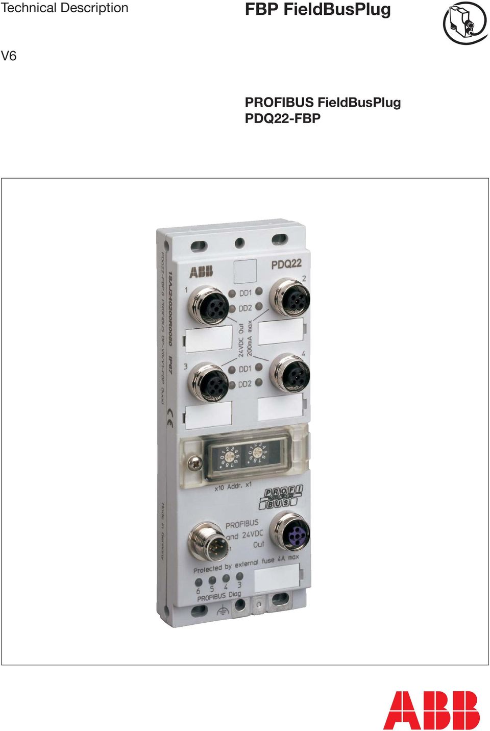
1 FBP FieldBusPlug V6 PROFIBUS FieldBusPlug
2 Please note the following Target group This description is intended for the use of trained specialists in electrical installation and control and automation engineering, who are familiar with the applicable national standards. Safety requirements The responsible staff must ensure that the application or use of the products described satisfy all the requirements for safety, including all the relevant laws, regulations, guidelines and standards. Using this Handbook Symbols This technical document contains sentinels to point the reader to important information, potential risks and precaution information. The following symbols are used: Sign to indicate a potential dangerous situation that can cause damage of the PDQ22 or connected devices or the environment. Sign to indicate important information and conditions. Sign that indicates a potential dangerous situation that can cause human injuries. Abbreviations FDT/DTM GSD DCS PLC HWD UPS FDT (Field Device Tool) is a technology for managing field devices. This technology has been established as an open specification and is therefore vendor independent. Device manufacturers add to their individual field devices a piece of software called Device Type Manager or DTM. See for more information. Geräte Stammdatei (German) which means a electronic data sheet of a device Distributed Control System Programmable Ladder Controller Hardware Definition File is similar to a GSD file and required for ABB s 800M Control Builder software to integrate field devices. Uninterruptible Power Supply Related Documents Technical Documentation PDP21-FBP/PDP22-FBP PROFIBUS DP Accessories FBP System Accessories UMC22-FBP (Software version 3.4) UMC22-FBP Atex (Software version 3.2) Document No. 2CDC D02xx 2CDC D02xx 2CDC D02xx 2CDC D02xx 2CDC D02xx - 2 -

3 Content 1. Overview System Overview Product Overview Required Components PROFIBUS Master Requirements System Limits Number of PROFIBUS Slaves Number of Connected Devices Cable length between PDQ22 and connected Devices Quick Start PDQ22 as a Modular PROFIBUS Slave PROFIBUS in a Nutshell Building a PROFIBUS Network with PROFIBUS DP FBP...12 Topology Examples...13 Setting the PROFIBUS Node Address...15 Connecting devices to PDP Control System Integration Configuring the PDQ Parameterization Integration with the GSD File Integration with the Device Type Manager (DTM) Cyclic Data Exchange Transmission of I/O Data Cyclic Diagnostics Information Acyclic Data Exchange (DP-V1) Diagnosis / Behaviour in Case of an Error Local Diagnosis PROFIBUS Diagnosis Power Supply Power Supply via Bus Cable Points to Consider Example Calculation Mounting, Grounding and Shielding Application Examples Technical Data Ordering Data
...20 4.5. Cyclic Data Exchange...21 4.5.1. Transmission of I/O Data...21 4.5.2. Cyclic Diagnostics Information...21 4.6.")
4 1. Overview 1.1 System Overview The FieldBusPlug connects automation, switch or controlgear devices with a PROFIBUS DP network. Up to four devices can be connected with one. PDQ22 PDQ22 PDQ22 PDQ22 PDQ22 2CDC352052F0006.eps MSD11 UMC22 Figure 1 shows a typical plant set-up that can be realized with the. In this example motor starters MSD11-FBP and motor controllers UMC22-FBP are connected to the. can be directly used together with PDP21-FBP / PDP22-FBP but also with any other PROFIBUS devices using the available accessories

5 1.2. Product Overview PDQ22 is a member of the ABB FieldBusPlug family of bus connectors. Presently plugs for PROFIBUS DP, DeviceNet, AS-I and Modbus RTU are available. PDQ22 allows the connection of up to four devices to PROFIBUS DP. This makes the integration of PROFIBUS devices that are located physically nearby more cost-effective. Up to four times more devices can be connected this way to a single PROFIBUS line. Mixed configurations are supported. This makes it possible to connect different devices such as MSD, MSR, UMC22 at the same PDQ22. Also different versions of a device can be connected at the same time. Devices are treated as single modules from the PROFIBUS point of view. This allows efficient engineering and simple integration into control systems and transparent access to each single device. Parameters can be set for each device separately. PDQ22 buffers the device parameters sent from the master during start-up. If a device is replaced it automatically gets the stored parameters. Monitoring and diagnosis data is collected from the devices and sent to the PROFIBUS master. PDQ22 allows building robust solutions. Intelligent devices such as UMC22 connected to PDQ22 are cyclically monitored. If devices fail the other devices are not affected. PDQ22 keeps running with the remaining devices and sends default values for the failed ones. Status LEDs for the bus and each device are available. In addition, you can also access status information via the field bus: this makes it possible to evaluate the details from a PLC or control system. Time-consuming searches for faults are therefore a thing of the past and maintenance times are kept to a minimum. PDQ22 supports PROFIBUS DP-V1. This means tools that use DP-V1 services for both configuration and parameterization can be used without limitations. Also maintenance and service tools accessing service data of the connected devices are well supported (e.g. ABB s 800xA Asset Management Solution). All FieldBusPlugs including PDQ22 are supplied via the bus cable. This means if the power supply of a device breaks the bus node is still alive and can signal the problem to the control system. It also provides the option to feed the plugs from a central UPS to increase the PROFIBUS availability. A bus line built with PROFIBUS FieldBusPlugs PDQ22 and PDP21 / PDP22 is a real party line without branches or drops. This means that the maximal PROFIBUS baud rate of 12 Mbit/s is possible, supposed the termination on both ends is done correctly and the maximal bus length is not exceeded. Because of the connection schema it is ensured that only at the ends of the PROFIBUS line termination resistors are used. Regarding the situation that many of the problems in conventional wired PROFIBUS lines are caused by loose contacts or wrong terminations, the FieldBusPlug system guarantees a faultless data transmission line between the master and the slaves and a simplified commissioning phase. For the connection between and the devices standard Sensor/Actor extension cable can be used

6 DD1 (red) LED: Error Indicator DD2 (green) LED: Function Indicator PDQ22 1 DD1 2 M12 plug for connecting devices DD2 24VDC Out 200mA max 3 4 DD1 DD2 Window to set the PROFIBUS node address: PROFIBUS: Connection from PROFIBUS slaves or PROFIBUS master (a-coded). x10 Addr: x1 2CDC342053F0006.eps Rotary switch left: Tens column Rotary switch right: Ones column PROFIBUS Diag 4 (red) LED: Error Indicator PROFIBUS Diag 3 (green) LED: Function Indicator PROFIBUS and 24VDC In Out Protected by externel fuse 4A max PROFIBUS Diag. PROFIBUS: Connection to further PROFIBUS slaves (a-coded). Ground connector Figure 2 Front view The figure above shows the. Devices such as the UMC22-FBP or other FieldBusPlug compatible devices can be connected at the upper four M12 (1...4) connectors. Only standard M12/M12 extension cable is required to connect the devices. As with all other FieldBusPlugs the M12 cable includes 24 V DC that can be used to supply the connected devices. A label per plug is foreseen for plant specific labelling. The PROFIBUS address can be set between 0 99 via two decode switches protected from a lucent cover. The lower two M12 connectors marked in light-grey are provided to connect the incoming and outgoing PROFIBUS line. PDQ22 realizes a real t-piece which automatically results in a party line topology. The LEDs on the bottom left corner are used for status indication of the PDQ22 and the PROFIBUS. See section 5 for details. All screwed shells are internally connected to the ground connector. With the help of the accessory CDA11-FBP.0 the PDQ22 can be DIN rail mounted Do not connect devices to the light-grey marked PROFIBUS connectors or vice versa. This can destroy the PDQ22, connected devices or other devices connected on the PROFIBUS bus! - 6 -
. Ground connector Figure 2 Front view The figure above shows the.")
7 1.3. Required Components To connect four devices (e. g. UMC22) to PROFIBUS the following components are needed: 1 x FieldPusPlug PROFIBUS DP 1 x PDA11-FBP PROFIBUS DP adapter cable Dsub9-M12 for connection to the PROFIBUS Master 1-4 x UMC22 Universal Motor Controller (only for the quickstart tutorial) 1-4 x ACS100-PAN Control panel for UMC22 (only for the quickstart tutorial) 1-4 x CDP15-FBP.150 Device connection with M12/M12 extension cable 1 x CDA11-FBP.0 DIN Rail Connector (optional) Accessory to make it possible to mount the PDQ22 directly on a DIN Rail. 1.4 PROFIBUS Master Requirements PDQ22 can be connected to all PLC or DCS systems that provide PROFIBUS DP connectivity. The following functions of PDQ22 can be accessed via PROFIBUS DP-V0: Configuration and parameterization after power on PDQ22 diagnosis messages Cyclic exchange of real-time data provided by the connected devices between PROFIBUS master and PDQ22 To use the full capabilities of connected devices it is beneficial that the master also supports PROFIBUS DP-V1 services. This allows: Acyclic read/write access to all parameter data offered from a device Online re-parameterization of a device from a class two master Integration of the devices into modern maintenance management systems such as 800xA s Asset Management System. 1.5 System Limits Number of PROFIBUS Slaves Via PROFIBUS at most 127 devices can be addressed in a network. Without repeaters only 32 devices can be operated per segment because of physical limitations of the RS485 standard line drivers and receivers. The number of 32 includes also repeaters and similar components! For every segment the maximum possible cable length is defined by the given baud rate. For more than 32 stations or larger segment length repeaters or RS485 to optical fibre converters can be used Number of Connected Devices Up to four devices can be connected to the PDQ22 at the same time. All the modules available in the PDQ22 GSD file ABB_0A09.GSD can be connected in any combination as required by the user. If connectors are not used, an "empty module" must be configured. The maximum frame sizes defined by PROFIBUS are ensured from the GSD in combination with the used master configuration tool Cable length between PDQ22 and connected Devices Cable length should not exceed 2 m. It is highly recommanded to use shielded cable for the connection
 Accessory to make it possible to mount the PDQ22 directly on a DIN Rail. 1.4 PROFIBUS Master Requirements PDQ22 can be connected to all PLC or DCS systems that provide PROFIBUS DP connectivity.")
8 2. Quick Start The following quick start tutorial shows how to set-up a small system consisting of a PROFIBUS bus master, the PDQ22 as a PROFIBUS slave and one or more UMC22 devices. Because there are so many different bus masters available only a general description can be provided. It is assumed that the reader is familiar with the concrete master in use. To follow the tutorial the parts described in section 1.3 (Required Components) are needed. The following figure shows the hardware set-up. UMC22-FBP PROFI- BUS- Master PDQ DD1 DD2 24VDC Out 200mA max 3 4 DD1 M12/M12 extension cable CDP15-FBP.150 DD2 24 V 0 V PDA11-FBP x10 Addr: x1 PROFIBUS and 24VDC In Out Protected by externel fuse 4A max PROFIBUS Diag. Set Address to 14 2CDC342054F0006.eps Figure 3: quick-start-set-up The hardware set-up for the quick start tutorial consists of a PDQ22 and the UMC22 (any other FBP device supported in the PDQ22 GSD file could also be used). For connecting the PDQ22 to a PROFI- BUS master the PDA11 cable is used. For device connection a standard M12/M12 cable is used. Installation and commissioning of the PDQ22 step by step: PDQ22 set-up: Mount the PDQ22 either on a DIN rail or fix it with screws in your control cabinet Set the PDQ22 slave address to 14. PROFIBUS node address Device connected to PDQ22 Port Use the PDA11 (Adapter Cable Dsub9-M12) to connect the PDQ22 with the bus master. Connect the red (+) and blue (-) strand of the PDA11 with a 24 V DC power supply. Set the termination switch on the PDA11 (green) to ON. For this setup no active PROFIBUS termination unit (PDR11) is required Connecting devices: Mount the UMC22 device UMC22 can be supplied from the PDQ22. Therefore set the switch on UMC22 to int Connect the UMC22 devices with the PDQ22 using a standard M12/M12 extension cable (Sensor/Actor cable)

9 Switch on the power supply: Both devices start working Set the UMC22 device address. Starting from the configured bus address (here 14) the device connected to port one must use address 41, the one connected to port two 42 and so on. In this example UMC22 is connected to the fourth port. Therefore UMC22 must use address 44. To change the UMC22device address press the up button until <Edit1> appears and press <Enter>. Press the down button until <Addr> appears and press <Enter> again. Set the address to 44 as shown: UP DOWN MENU LOC REM ENTER for more info on how to configure the UMC22 see the technical manual of UMC22. Because the PROFIBUS master is not yet configured the red PROFIBUS diagnosis LED is flashing and the green diagnosis LED is on. Device diagnosis LEDs ports 1 to 3: The green LEDs are on because PDQ22 is not yet configured and no device is connected. Device diagnosis LED of port 4: After a few seconds the green LED is on and the red LED is flashing. This indicates a repairable error i.e. wrong device type connected or wrong address of the connected device. Configuration: Configuration and parameterization of the devices must be done in the configuration tool provided by the bus master vendor. In principle the following steps are usually required: Import the GSD file of the PDQ22 (ABB_0A09.GSD) into the configuration tool. Now the configuration tool knows the device and can use it. Create a slave below the master. Usually this can be done in tree view representing the configured devices. Take care that the slave address matches the address is set at the PDQ22 Insert two empty modules for port one and two. Insert a UMC22 for ports three and four. Leave the parameters of the two configured UMC22 as it is for now The figure below shows how the configuration looks like in the ABB control system (Freelance) - 9 -

10 2CDC343055F0006.eps Figure 4: PDQ22 configured with two empty modules at port one and two. At port three and four two UMC22 are connected. Now the configuration is complete. Usually a kind of download process must be done to store and activate the new configuration in the PROFIBUS master. Perform this step for your system now. Commissioning Reboot the PDQ22 (remove the PROFIBUS cable for a few seconds). This forces the bus master to send the new configuration to the PDQ22. Please note: When the configuration (i.e. number or type of connected devices) changes the PDQ22 must always be rebooted. After initialization only the green PROFIBUS diagnosis LED should lit which indicates the cyclic PROFIBUS communication is up and running. The green diagnosis LEDs of port one and port two are on to indicate no error. The red LED of port 3 is flashing indicating that the connection to the configured device is missing The green LED of port 4 is on indicating normal operation with the connected UMC22. Summary During this short tutorial you have Set-up a simple PROFIBUS network with PDQ22 and UMC22 Set the PDQ22 PROFIBUS address Connected a UMC22 to PDQ22 and set the correct device address Configured the PDQ22 in your PROFIBUS master using the GSD file Downloaded and activated the cyclic PROFIBUS communication To learn more about the device diagnosis capabilities of PDQ22 perform the following experiments and observe the diagnosis LEDs of the related ports. Detailed explanation about the LEDs can be found in section 5 "Diagnosis / Behaviour in Case of an Error" Remove the UMC22 from port four and leave it unconnected (device missing) Reconnect the UMC22 to port two (wrong device connected) Change the UMC device address to 43 and connect it again back to port four (device with wrong address connected)

11 3. PDQ22 as a Modular PROFIBUS Slave 3.1. PROFIBUS in a Nutshell PROFIBUS DP is at present the most common field bus for industrial applications worldwide and is standardized in IEC61158 together with other field bus protocols. The definition of the PROFIBUS is based on the experience concerning data transmission collected during long years. One basis is the ISO/OSI layer model that represents an ordering and description scheme for data transmission systems. It divides the way between the CPU interface and the physical medium into seven layers. Fieldbus systems normally use only three of them: ISO / OSI Layer 7 Transmitting CPU Application layer Receiving CPU Application layer Interface to the application program (CPU) with application oriented commands (read, write) Layer 2 Layer 1 Data-link layer Physical layer Data-link layer Physical layer Access (to the line) control, telegram (start, length,...), data security (e.g. CRC=Cyclic Redundancy Code) Definition of the medium (Twinax, optical fiber,...), coding ( 1 = - 4 V), transmission speed (baud rate).. Transmission medium (physical) As a result of the ISO/OSI layer model each layer can be defined separately and (nearly) independent of the other layers. Indeed it is possible and common to use conventional cables but also optical fibers as physical layer for the PROFIBUS DP or have a mixture of both in a single bus configuration. For the application layer there are also different versions possible e.g. PROFIBUS DP-V0, PROFIBUS DP-V1 but also others that are not regarded here. The PROFIBUS standard has defined different network topologies. The most commonly used one is the Party Line topology where one device is connected after the other. PROFIBUS has evolved over time. The first services offered by PROFIBUS are the so-called V0 services. They define block parameterization, configuration, cyclic data exchange and diagnosis information exchange. DP-V0 only allows writing the complete parameter set in one block. The bus master sends the parameter block to the slave during power-up of the slave/device. Some control systems also allow sending the parameter block during normal operation. Later on the PROFIBUS DP-V1 specification introduced new acyclical read/write services within the context of the PROFIBUS DP-V1 expansions. These acyclical services are inserted into special telegrams during ongoing cyclical bus operation and thus ensure compatibility between PROFIBUS DP-V0 and PROFIBUS DP-V1. Via diagnosis telegrams detailed information about the device status can be transmitted to a master. Beside device related diagnosis also process related diagnosis is provided by modern field devices. Take a trip caused by overload of a motor as an example. Diagnosis data are automatically read by the PRO- FIBUS master if it receives a fault info within a monitoring telegram. With V1 also the handling and the content of diagnosis data was further standardized and is different from V

12 3.2 Building a PROFIBUS Network with PROFIBUS DP FBP Networks with PROFIBUS DP FieldBusPlug The main feature of the FieldBusPlug system is that all devices with the neutral FBP interface can be connected to several field busses using the appropriate FieldBusPlug. This means that a PROFIBUS DP slave is built up of a device with the neutral interface and the PROFIBUS DP FieldBusPlug PDQ22 The existing PROFIBUS DP plugs such as the PDP22 and PDP21 can be used in the same network without any problems. All plugs follow the same system concept. Important Features of Bus Lines Created with PDQ22 The PDQ22 represents a real tee unit (T-unit). This means: If the bus node built in the PDQ22 fails all remaining FieldBusPlugs are still connected with the bus master. All FieldBusPlugs including PDQ22 are supplied via the bus cable. This has several benefits: If the power supply of a device fails the bus node is still alive and can signal the problem to the control system. This is of special value in Motor Control Centers (MCCs) where the bus node is often mounted outside a drawer. Even if the drawer is removed the bus node is still alive and can signal this condition to the control system. It also provides the option to feed the plugs from a central UPS to increase the PROFIBUS availability even further. Under some circumstances it is possible to supply the devices via the bus cable with 24 VDC saving local supplies. A bus line built with PDQ22 is a real party line without branches or drops. This means: The maximum baud rate 12 Mbit/s is possible, supposed the termination on both ends is done correctly and the maximum bus length is not exceeded. The contacts - pins and jacks - are gold plated. This means: Concerning the contacts the PDQ22 avoid that faults caused by loose or bad contacts. Only at the ends of the bus line termination resistors are possible. This means: In the standard topology as shown below only at the ends of the line terminations are possible. At the DSUB9 connector mounted on the bus master the termination resistor set has to be switched ON and at the other end of the bus line the bus termination unit must to be mounted. On one bus line the FieldBus Plugs PDQ22 and PDP21/PDP22 can be used directly together in any combination. The products implement the same system idea! Regarding the situation that most of the problems in conventional wired PROFIBUS lines is caused by loose contact or wrong termination, the FieldBus Plug system guarantees a faultless data transmission line between the master and the slaves
.")
13 Topology Examples This subsection describes some possible topologies that can be realized using PDQ22 and PDP22 FieldbusPlug. Pure FieldbusPlug lines as well as mixed configurations are described. UMC22-FBP connected to PDQ22 -FBP via M12/M12 Extension Cable CDP15-FBP 24 V 0 V PROFI- BUS- Master CDP15-FBP Extension Cable 2CDC342056F0006.eps PDA11-FBP PROFIBUS DP Adapter Cable Dsub9-M12 PROFIBUS DP FieldBusPlug PDX11-FBP PROFIBUS DP Extension Cable PDR11-FBP PROFIBUS DP Active Termination Unit Figure 5: Topology Example 1: Only as Slaves Different Devices connected to PDQ22 -FBP via M12/M12 Extension Cable CDP15-FBP PROFI- BUS- Master 24 V 0 V CDP15-FBP Extension Cable PDR11-FBP PROFIBUS DP Active Termination Unit 2CDC342057F0006.eps PDA11-FBP PROFIBUS DP Adapter Cable Dsub9-M12 PDP22-FBP PROFIBUS DP FieldBusPlug PDX11-FBP PROFIBUS DP Extension Cable PROFIBUS DP FieldBusPlug Figure 6: Topology Example 2: and PDP22-FBP as Slaves

14 If the distance between the bus master and the slaves is longer it may be necessary to feed in 24 V DC for the FieldBusPlugs on a second place. Check with: Supply Calculation scheme. CDP15-FBP Extension Cable 24V DC PROFI- BUS- Master PROFI- BUS- Slave PROFI- BUS- Slave 24 V 0 V PDA11-FBP PROFIBUS DP Adapter Cable Dsub9-M12 PDP22-FBP PROFIBUS DP FieldBusPlug PROFIBUS DP FieldBusPlug PDA12-FBP PROFIBUS DP Adapter Cable M12-Dsub9-M12 PDV12-FBP PROFIBUS DP Feed-In connector 2CDC342058F0006.eps Figure 7: Topology Example 3: Long Bus Cables (Feed In) 24 V 0 V PROFI- BUS- Master CDP15-FBP Extension Cable Repeater 2CDC342059F0006.eps PDA11-FBP PROFIBUS DP Adapter Cable Dsub9-M12 PDM11-FBP PROFIBUS DP cable with plug 24V DC PDF11-FBP PROFIBUS DP cable with socket PDR11-FBP PROFIBUS DP terminating resistor Figure 8: Topology Example 4: PROFIBUS line with Repeater
 24 V 0 V PROFI- BUS- Master CDP15-FBP Extension Cable Repeater 2CDC342059F0006.")
15 Setting the PROFIBUS Node Address The PROFIBUS master uses the unique slave address for addressing the slave. The slave address of PDQ22 can be set using two rotary decode switches. The left one is used to set the decade the right one to set the ones column. The node address can be set between The default setting is 99. After changing the PROFIBUS node address a power down and up cycle must be performed. Address 00 is reserved and must not be used Theoretically 127 nodes can be connected to a PROFIBUS network. In practise the number of connectable slaves is smaller because also the cyclic (class one) and optional acylic (class two) masters counts as nodes. Also every repeater counts as a node. Furthermore the physical length of a network and the load must be considered (see section 6). Each device connected to a PROFIBUS network must have a unique PROFIBUS node address. If two devices have the same address both devices leave cyclic data exchange. Dependant of the master implementation other unintentional effects may happen (e.g. the whole line is shut down). Connecting devices to PDP22 At creation time of this document it is possible to connect the following devices to PDQ22: UMC22-FBP (V3.0 - V3.4), MFI21-FBP, MSD11-FBP, MSR22-FBP, Sensors, WDI100 A up to date overview is provided always in the latest GSD file (ABB0A09.GSD) (see section 4.3). Connecting intelligent devices to PDP22 All intelligent devices that can be connected to PDQ22 usually maintain their own device address. PDQ22 uses this device address to ensure that no device with a wrong address is operated via the PDQ22. This prevents a user to accidentally connect a device to a wrong port (e.g. when mounting a drawer in a wrong position). There is a fix device address associated with each port. This address is derived from the PROFIBUS node address. The ones column of the PROFIBUS node address becomes the tens column of the device address. The port number where the device is connected to becomes the ones column of the device address. Example: The selected PROFIBUS node address is 14. The resulting address for the devices are 41,42,43 and 44 as shown in the figure below. PROFIBUS node address 1 Device connected to PDQ22 Port If a particular scheme is taken into account when allocating the Profibus addresses, an interchanging of devices can be prevented in a Motor Control Center (see section 8). Connecting simple devices to PDQ22 M12 sensors such as proximity switches or actors like the MSD11-FBP can also be connected to the PDQ22. In this case the corresponding PDQ22 port operates in the so-called I/O mode where two digital inputs and one digital output are available per port. No device address needs to be set in this case. It is possible to create mixed configurations where both, simple and intelligent devices, are connected at the same time
 and optional acylic (class two) masters counts as nodes. Also every repeater counts as a node.")
16 4. Control System Integration Device integration can be realized for practically every control system via the GSD file. For a more advanced integration (e.g. function blocks, face-plates etc.) control system vendors typically offer an integration service. Please contact the according control system vendor to find out the available option. Control system integration of PROFIBUS devices consists of two steps configuration and parameterization. The following sections describe these two steps Configuring the PDQ22 In the PROFIBUS world configuration means the arrangement of the different modules available in a modular slave. This usually results in a change of the organization or a change in the length of the cyclic data sent to or received from the master. Therefore it is necessary to restart the PDQ22 once after the configuration was changed. PDQ22 offers the possibility of mixed configurations. This means it is possible to connect different modules to the same PDQ22 at the same time. E.g. it is possible to connect two UMCs and two MSDs or any other combination. It is also possible to connect different versions of the same device e.g. three UMCs with software version 3.1 and one UMC with software version 3.3. The GSD-file/DTM provided with the PDQ22 automatically ensures that in all supported combinations the maximum frame size of PROFIBUS is not exceeded. PDQ22 requires that always four modules are configured. In the case that not all ports are required an empty module must be configured. For the PROFIBUS expert Cold Start The CheckCfg telegram sent from the PROFIBUS master defines the reference configuration. It is accepted if it is error free. Otherwise a negative reply with appropriate diagnosis information is sent to the master. The PDQ22 arrives in the cyclical data exchange mode even if the reference configuration sent from the master does not correspond with the actual configuration found during device start-up! This makes it possible to do engineering of a plant even if the modules are not yet physically available and plugged into the PDQ22. For not yet connected devices the PDQ22 sends default values (zeros) and sets the appropriate diagnosis information. Online Reconfiguration PDQ22 does not support Hot Configuration In Run as supported by some ABB control systems. Whenever a configuration change is done, the PDQ22 must be restarted, to ensure that the configuration gets accepted Reaction on wrong configuration telegrams Wrong configuration or parameter telegrams can occur if the used GSD file that does not belong to a device or the device version. In this case the PDQ22 does not accept the configuration telegram and leaves cyclic operation mode or does not start the PROFIBUS communication

17 4.2. Parameterization In the PROFIBUS world parameterization means the definition of properties of already configured modules. E.g. changing the value of a parameter. The following parameters are provided by the PDQ22 itself: Parameter Name Parameter Values Explanation Block-Parameter Port 1 Use Block-Parameters Port 1 (default setting)ignore Block- Parameters Port 1 Block-Parameter Port 2 Use Block-Parameters Port 2 (default setting)ignore Block- Parameters Port 2 Block-Parameter Port 3 Use Block-Parameters Port 3 (default setting)ignore Block- Parameters Port 3 Block-Parameter Port 4 Use Block-Parameters Port 4 (default setting)ignore Block- Parameters Port 4 If this parameter is set to Use Block Parameters Port x the PDQ22 forwards parameters sent from the master during bus start to the device connected at port x. Else the parameters are not forwarded. This parameter is useful if devices are preconfigured in the factory (e.g. panel builder) and the configuration should not be overwritten from the PROFIBUS bus master during commissioning of a plant. The parameters of the connected devices are available on module level
ignore Block- Parameters Port 4 If this parameter is set to Use Block Parameters Port x the PDQ22 forwards parameters sent")
18 For the PROFIBUS expert Behaviour at cold start During start-up the PDQ22 waits for a parameter telegram from the bus master. Starting the cyclic PROFIBUS communication is only possible if a correct parameter telegram was received. The parameter telegram is then split into parts and sent to the connected devices. If wrong parameters were sent (e.g. parameter out of range) the devices (not the PDQ22) may signal an error condition which is translated into an appropriate device specific diagnosis message. Online re-parameterization of devices Because parameter changes do not affect the structure of the I/O data re-compilation of the user application in the master is usually not necessary. In some control systems a restart of the master must be performed that makes online re-parameterization impossible. Other masters are not subject of this limitation and support online parameterization. PDQ22 and FieldBusPlug devices such as the UMC22 are able to receive parameter telegrams without leaving the cyclic operation mode. The PROFIBUS specification allows the online re-parameterization only if the device is not operated in V1 mode. This means that no acyclic communication is allowed from the cyclic bus master (class one master). However systems using a so-called class 2 master for sending V1 requests and supporting sending a new parameter telegram whilst online are capable to do online re-parameterization. If a specific control system is able to do online re-parameterization should be found in the documentation of this system. Sending new parameters during cyclic operation can be critical. If parameters are out of range or can not be accepted from the device for a specific reason a device might leave the cyclical operation mode and enter an error of fail-save mode. Please consult the manual of the connected devices for more information. Reaction on Wrong Parameter Telegrams The PDQ22 does not check the parameters itself. This can only be done from the connected devices. In case of a faulty parameter telegram was recived (e. g. wrong length) the PDQ22 leaves the cyclical operation mode and waits for a new parameter telegram

19 4.3. Integration with the GSD File Besides the physical connection of a device to a PROFIBUS line, the engineering of the whole PROFIBUS system in the PROFIBUS master is necessary. Every modern PLC (Programmable Ladder Controller) or DCS (Distributed Control System), that can be used as PROFIBUS master, offer the possibility to configure and parameterize devices connected to the master. As a basis electronic data sheets are used for that purpose. In the PROFIBUS world these electronic data sheets are called GSD files. Within these files the all properties relevant for operating the slave are described (e.g. supported baud rates, max. number of modules etc.). The GSD file ABB_0A09.GSD is contained in the Software Engineering Package PBE91-FBP.010x 1SAJ924091R010x.ZIP The ZIP file can be obtained from ABB s web site ( or on the FBP Sytem CD (2CDC E04xx). Please ask your local sales office for it. The GSD file is a normal text file and can be changed with any text editor. Proper function of the slave can be only guaranteed with the original file provided by ABB. Manipulation of the GSD file can cause critical errors and is at your own risk PDQ22 is a so-called modular slave. The configuration of a modular slave is in opposite to a compact slave flexible regarding the number of connectable modules. In the GSD file each module supported from PDQ22 is described including all its properties. This includes: Amount of data sent from the master to the slave (output data) Amount of data sent from the salve to the master (input or monitoring data) Adjustable parameters Diagnostics Information In addition system limitations are defined such as the maximum number of connectable devices etc
. The GSD file ABB_0A09.")
20 The following figure shows the PDQ22 in an engineering tool from ABB. Different configurations are shown in the figure below: PROFIBUS node 1 shows the option to leave ports unconnected (first port). In such a case an empty module must be configured. Empty module(s) can appear in every position of the configuration. PROFIBUS node 2 with four MSR22 devices. PROFIBUS node 3 shows a totally mixed configuration. Any modules supported in the PDQ22- GSD file can be used together. 2CDC343060F0006.eps Figure 9: DCS integration of the PDQ22 and connected devices using the PDQ22 GSD file. For each PDQ22 four modules are configured. If not all physically available plugs are used an empty module must be inserted Integration with the Device Type Manager (DTM) Beside the option to integrate devices with GSD files more and more modern control systems support the FDT/DTM concept. FDT (Field Device Tool) technology standardizes the communication interface between field devices and systems. The device supplier develops a new Device Type Manager (DTM) for each of its devices or group of devices. The DTM encapsulates all the device-specific data, functions and business rules such as the device structure, its communication capabilities, internal dependencies, and the Human Machine Interface (HMI) structure. The DTMs provide functions for accessing device parameters, configuring and operating the devices, and diagnosing problems. At creation time of this document, the DTM is not avaliable. the development is under preparation

21 4.5. Cyclic Data Exchange Transmission of I/O Data Transmission of input - and output data (or command and monitoring data) from the connected devices is the major task of the PDQ22. PDQ22 receives input data from the master, slits it into parts as defined by the configured modules and sends it to the connected devices. On the other side it receives data from the devices, assembles it to a transmit frame and sends it to the PROFIBUS master. The following figure shows this process. PDQ22 Device 1 Command data from master 0 0 m Diassamble frame from master and forward data to devices 2 Monitoring data from devices Assamble data from devices into one frame that is sent to the master 3 4 2CDC342061F0006.eps Figure 10: PDQ22 receives input data from the master, slits it into parts as defined by the configured modules and sends to the connected devices. On the other side it receives data from the devices, assembles it to a transmit frame and sends it to the PROFIBUS master. Data length of the PROFIBUS frames is determined by the modules (devices) configured in the PROFIBUS master. Input and output data length per module could be different. Same modules (e.g. UMC22 V3.3) have same data lengths Cyclic Diagnostics Information As part of the cyclic data frame there is the possibility to signal the availability of diagnosis (so-called extended diagnosis) to the master. As soon as one of the connected devices or the PDQ22 itself has signalled that diagnosis data is available this bit is set. For a description of the extended diagnosis frame see section 5.2 PROFIBUS Diagnosis
22 4.6. Acyclic Data Exchange (DP-V1) This section describes the functions and terms used for operating PDQ22 on PROFIBUS DP-V1 masters. Refer to the PROFIBUS user organization or visit for extensive technical information on PROFIBUS DP-V1. Beside the cyclic data exchange PROFIBUS has defined an option to exchange data on an acyclic basis with is called DP-V1. The data organization i.e. where data can be accessed is defined by the so-called slot/index addressing schema. The PROFIBUS specification allows free assignment of available data to slots and indexes. Therefore a mapping schema on how data can be access at connected devices was defined for PDQ22. The PDQ22 itself is accessible at slot 0. Devices are accessible beginning at slot 1. The following table provides an overview about the mapping Incoming V1 request on address Mapping to device connected to plug Slot index from device point of view Slot 0, Index PDQ22 itself Slot 0 (index 255 is reserved for I&M functions) Slot 1 5, Index Port 1 Slot 0 4 Slot 6 10, Index Port 2 Slot 0 4 Slot 11 15, Index Port 3 Slot 0 4 Slot 16 20, Index Port 4 Slot 0 4 Slot , Index PDQ22 itself Reserved The maximum of 255 slots can be used (0 254). Acyclic services can be initiated from a class 1 or a class 2 master. The class 1 master is at the same time the master driving the cyclical data exchange. Class 2 masters are usually only temporarily connected to a PROFIBUS line e.g. a PC with a PROFIBUS interface card. The class 1 master can access all data provided from the device. Unfortunately the GSD file does not specify which data is available via V1. The meaning of the data accessible via V1 is in principle vendor specific. But for some devices standardization took place by the PNO (Profibus Nutzer Organisation). This specification is called profile and should allow a vendor independent interpretation of the data. For more information see the PNO website
23 For the PROFIBUS expert V1 Requests from a Class1 Master Different master classes are distinguished in a PROFIBUS DP-V1 network. The so-called C1 master mainly performs the cyclical data exchange with the slaves. A typical C1 master is a control system, such as a PLC or DCS that exchanges cyclical process data with the slave. If the DPV1 function has been activated via the GSD file, also acyclical connections between a C1 master and a slave can be established when the cyclical connection o is being established. If a class 1 master uses V1 services, it is physically and logically the same bus node doing V0 and V1 communication. Before acyclic messages can be used for the C1 master a device must have entered the cyclic operation mode. This means that the PDQ22 must be first configured and parameterized before acyclic requests from a class 1 master are possible. PDQ22 supports V1 requests from a class 1 master. Please see section Online Re-Parameterization for further details. V1 Requests from a Class2 Master A C2 master can not perform cyclical data exchange with the slaves. It is logically a different bus node than a C1 master. Examples for a typical C2 master are visualization systems, temporary installed programming devices (Notebook / PC) or maintenance management tools. The C2 master uses exclusively acyclical connections for the communication with the slaves. V1 connections allow for cyclical data exchange with the slaves by means of Read or Write services. Several C2 masters can be active in a DP-V1 network. The number of C2 connections, which are established to a slave simultaneously, are determined by the slave. PDQ22 supports up to 3 concurrent class 2 connections. 5. Diagnosis / Behaviour in Case of an Error PDQ22 provides detailed diagnosis information about the status of the connected devices, its own status and the status of the PROFIBUS connection. Diagnosis information is shown a) with the locally available lamps and b) via the standard PROFIBUS services. The possibilities of locally available diagnostics are described in the next section. PROFIBUS diagnosis is described in the section following the next section Local Diagnosis Diagnosis information is locally displayed using two LEDs (Light Emitting Diodes) located beside each M12 device connector. Four LEDs located at the bottom left of the PDQ22 indicate the status of the PDQ22 itself
24 The following figure explains the status codes used for the device connectors one to four. In this case the upper left connector (port 1) is shown as an example. DD2 Green (bottom) DD1 Red (top) Status 2CDC342069F0006.eps 1 DD1 DD2 Off Off Power supply missing On Off Normal operation Flashing Flashing Self-test running (during power on) Flashing Off PDQ22 waiting for communication with device. If during power on no communication could be established within 3s an error is set for this port. Off Flashing Repairable error communicatiom to the device interrupted*). On Flashing Repairable error wrong device type connected or wrong device address*). Off On Non-repairable error. Replacement of the device might be necessary. *) Only for intelligent devices PDQ22 status is shown with the four LEDs located in the lower left. The leftmost two LEDs are presently not used. The following table describes all possible diagnosis states. LED 3 Green (rightmost) LED 4 Red (2nd from right) Status Off Off Power supply missing On Flashing Serious error. Possible cases are: No connection to PROFIBUS master established Different slave addresses configured in the master and the PDQ22 Flashing On Wrong number of parameters received. Off On PROFIBUS timeout: Connection to the PROFIBUS master was longer interrupted than configured. Please note that the timeout time must be configured in the master. On Off Normal operation Flashing Flashing Self-test during power on running. 2CDC342070F0006.eps Protected by externel fuse 4A max PROFIBUS Diag
25 5.2. PROFIBUS Diagnosis Standard Diagnosis: The format of the standard diagnosis data is defined within the PROFIBUS standards (IEC 61158). It consists of 6 octets that cannot be influenced by the field device manufacturer. The diagnosis information is related to the communication layer and covers run-up diagnosis scenarios such as the device identification, communication mode information (FREEZE, SYNC), readiness, availabilities, watchdogs, parameterization and configuration faults. For details see IEC , to Bit 7 in octet 3 (the Ext_Diag_Overflow flag) is used by the PDQ22 to indicate more diagnosis information then fits into the actual diagnosis message length. Extended Diagnosis: PDQ22 offers extended diagnosis to make the diagnosis data of the connected devices available to the PROFIBUS master. The extended diagnosis telegram has the following format: Byte in the extended Meaning diagnosis telegram 0 Block length (always 44 with PDQ22) 1 Status type (always 0x81 = Status Mode) 2 Slot number (always zero) 3 Status specifier (always zero) 4 11 Diagnosis status of PDQ22 itself Diagnosis data of device connected to port Diagnosis data of device connected to port Diagnosis data of device connected to port Diagnosis data of device connected to port 4 The content of byte 12 to 43 is defined by the devices connected to PDQ22. PDQ22 does not touch the content of these bytes. Please consult the device s technical manual about their content. Bytes 4 to 11 are reserved for the PDQ22 itself. Bytes 4 to 7 provides port related diagnosis. Byte 4 belongs to port 1, byte 5 to port 2 and so on. If all bits of a byte are zero, the process data sent for this device is valid. If any of the bits is set to one, process data of the related port is invalid. As a consequence PDQ22 forces the cyclic process data of this port to zero. For each port the following diagnosis information is available: Intelligent device with wrong device address connected Intelligent device connected, but wrong device type Intelligent device engineered in master, no intelligent device identified (not connected or non intelligent device connected e.g. sensor). No device engineered - If the plug should not be used an empty module has to be engineered. Byte 4 to 7 reserved
26 6. Power Supply The supply of the PDQ22 is always made via the bus cable. This enables the PDQ22 to send the actual e.g. faulty status to the control station even when the connection to a device is removed or when a device is switched off. Additionally it is possible to supply simple components such as proximity switches or actors like the MSD11 and MSR22 via the PDQ22. Some devices allow to be supplied externally (via terminals) or internally (via bus cable) setting the EXT/INT switch to EXT or INT respectively. Consult documentation of these devices. Larger devices cannot be supplied via the bus line. The supply current per port should not exceed 200 ma (4 x 200 ma per PDQ22). Maximum current for the PROFIBUS line in total is 4 Ampere (without additional feed-in connectors) and must be protected with a fuse (T4 or 4 A gl/gg). To be noticed: Prefer separate supply units or separately fused supply circuits for the FieldBusPlug line and the devices. Check the supply situation using the calculation scheme in the chapter below. Don t forget to check the total bus length Power Supply via Bus Cable Points to Consider Supposing all devices are supplied externally, the supply has to feed all FieldbusPlugs connected to the bus (PDQ22 and PDP22 if available). Their supply current depends on the voltage (below typical values for PDQ22): Supply voltage 19.2 V (min. allowed supply voltage) 24 V 31.2 V (max. allowed supply voltage) Supply current typ. 39 ma 31 ma 24 ma
27 To simplify the calculation the scheme below uses the highest of the currents but - on the other hand - does not regard the increased copper resistance and voltage loss for higher environment temperatures. All slaves even the slave most distant from the supply unit need to be supplied with min V DC including ripple. That means that the power supply unit at the beginning of the line has to provide a higher voltage to compensate the loss due to the line resistance. Master 4 A Power supply S S S S S S S S S S S average line length between 2 slaves 2CDC342062F0006.eps line length to the most distant slave Figure 11: Scheme PROFIBUS DP line The recommended power supply unit can be adjusted to 28 V DC Power Supply 24V / 5A adjustable Order code: 1SVR R0100 Type: CP-24/5.0 Remark: The maximum number of physical stations on one bus segment is 32, defined by the RS485 standard. For more than 31 slaves an additional segment (coupled with repeater) has to be provided. That needs normally a separate supply unit. In accordance with this fact the calculation below provides max 31 slaves + one master. Normally each repeater and RS485 / fiber-optic converter represents also one physical station each on the RS485 bus line. The calculation with the calculation scheme below takes into account: The most distant slave - situated at the end of the scheme - needs at least 19.2 V DC Line resistance (0.5 mm²) (can be changed): /m Additional info: Max. output voltage of above recommended supply unit: 28 V
28 6.2. Example Calculation In this section a sample calculation is shown to check that, with a given bus cable length, current consumption per node and number of nodes per line can be supplied. For this calculation an Excel sheet is provided. The excel file is contained in the Software Engineering Package PBE91-FBP.010x 1SAJ924091R010x.ZIP The ZIP file can be obtained from ABB s web site ( or on the FBP Sytem CD (2CDC E04xx). Please ask your local sales office for it. Calculation procedure 1. Set number of slaves, e.g. including 10% spare slaves, in the blue field in the Excel sheet. 2. Set average length of the bus line between the slaves in the green field of the Excel sheet. It is necessary to consider also the max. length of the signal lines. Individual length can be filled in the green cells near the slaves. 3. Fill in current of the slaves in the yellow field. Individual currents can be filled in the yellow cells near the slaves. With this figures the Excel sheet calculates the supply voltage available for each slave and the total current consumption. The blue mark shows where the master is located. If the voltage or current exceeds the maximum allowed values the according fields (sum current or voltage on slave) are marked in red. Red indication starts with the slave where the max. allowed value is exceeded the first time. The following figures are cutouts from the Excel sheet "PROFIBUS-DP_PowerSupply-via-Bus-Cable_Calculation.xls" Power Supply via Bus Cable, Calculation (continued) Calculation procedure 1. Define number of slaves, e.g. including 10% spare slaves: Example: 25 slaves ---> Master at the row of the 26th slave Define average length of the bus line between the slaves: 3,0 m The total length appears in the row of the master, green cell. It is necessary to consider also the max. length of the signal lines. Individual length can be filled in the green cells near the slaves. 3. Fill in current of the slaves: 40 ma The current of a slave is the calculated sum of the current consumption of a PDQ22 or a PDP21 or a PDP22 and the current consumption of the connected slaves ( please find them in the accordant technical data sheet ). Example... PDQ22 = 30 ma Individual currents can be filled in in the yellow cells near the slaves. Result: Voltage in the row of the master to be delivered by the power supply, total Current and total Bus Length. This supply voltage must not exceed 31,2 volts! Result: Sum Current The calculated sum of all currents in a bus line must not exceed 4000 ma (System Limit)!
DeviceNet Bus Software Help for Programming an Allen Bradley Control System
 FBP FieldBusPlug V7 DeviceNet Bus Software Help for Programming an Allen Bradley Control System DeviceNet Software Help for Programming an Allen Bradley Control System Contents Page General Purpose...
GE Power Controls FIELDBUS APPENDIX PROFIBUS DP. Doc. No.: ASTAT Plus PB_Appendix-v0
 GE Power Controls = FIELDBUS APPENDIX PROFIBUS DP = Doc. No.: ASTAT Plus PB_Appendix-v0 Fieldbus Appendix: PROFIBUS DP 1 Fieldbus Introduction...... 2 1.1 Introduction to Profibus-DP... 2 1.2 Network Overview...
DVPPF02-H2. PROFIBUS DP Slave Communication Module Application Manual
 DVPPF02-H2 PROFIBUS DP Slave Communication Module Application Manual Warning Please read this instruction carefully before use and follow this instruction to operate the device in order to prevent damages
I.S. 1 remote I/O system Redundant coupling via PROFIBUS DP
 I.S. 1 remote I/O system Redundant coupling via PROFIBUS DP 1. Functions An I. S. 1 fieldstation can be equipped with a primary and a redundant central unit (), whereby each has its own independent PROFIBUS
DeviceNet Communication Manual
 DeviceNet Communication Manual Soft-Starter Series: SSW-07/SSW-08 Language: English Document: 10000046963 / 00 03/2008 Summary ABOUT THIS MANUAL... 5 ABBREVIATIONS AND DEFINITIONS... 5 NUMERICAL REPRESENTATION...
ENET-710. ENET-710 - Ethernet Module ENET-710 JAN / 06 FOUNDATION
 ENET-710 ENET-710 - Ethernet Module JAN / 06 ENET-710 FOUNDATION E N E T 7 1 0 ME smar www.smar.com Specifications and information are subject to change without notice. Up-to-date address information is
SIMATIC NET. CP 243-2 AS-Interface Master B C. Preface Contents. Technical Description and Installation Instructions Interface to the User Program
 Preface Contents SIMATIC NET CP 243-2 AS-Interface Master Manual Technical Description and Installation Instructions Interface to the User Program 2 in the S7-200 CPU Access to the Data of the AS-i Slaves
CMC-PD01 PROFIBUS DP Slave Communication Card Operation Manual
 CMC-PD01 PROFIBUS DP Slave Communication Card Operation Manual CMC-0205820-01 Table of Content 1 Introduction to CMC-PD01... 2 1.1 Product Introduction... 2 1.2 Features... 2 2 Product Profile and Outline...
Set for PROFINET IO in IP20 TI-BL20-EN-PN-4
 Cable max. 50 m between interface and read/write head Connection of up to 4 read/write heads via BL ident extension cables Mixed operation of HF and UHF read/ write heads Connectors /S2500 Type code Ident
Application/Connection Examples
 This Quick Start Guide is designed to familiarize the user with the connection and configuration of the DTS-305 DIN rail mounted single / 3 phase power & energy meter with RS-485 or TCP communications.
Brake module AX5021. Documentation. Please read this document carefully before installing and commissioning the brake module!
 Documentation Brake module AX5021 Please read this document carefully before installing and commissioning the brake module! Version : 1.2 : 2012.03.05 Date Article-no. : TDmlAX-5021-0000-0200 Page 2/8
Programmable set for Ethernet Modbus/TCP in IP20 TI-BL20-PG-EN-8
 CoDeSys-programmable acc. to IEC 61131-3 Cable max. 50 m between interface and read/write head 10/100 Mbps LEDs for display of supply voltage, group and bus errors as well as status and diagnostics Connection
Product Information. Gateway For Connecting EnDat Encoders to PROFIBUS-DP
 Product Information Gateway For Connecting EnDat Encoders to PROFIBUS-DP April 2012 PROFIBUS Gateway For Connecting EnDat Encoders Encoders with EnDat interface for connection via gateway All absolute
PROFINET IO Diagnostics 1
 PROFINET IO is a very cost effective and reliable technology. However, extensive installations can have thousands of PROFINET IO devices operating on many networks. The reliable operation of these networks
Process Control and Automation using Modbus Protocol
 Process Control and Automation using Modbus Protocol Modbus is the fundamental network protocol used in most industrial applications today. It is universal, open and an easy to use protocol. Modbus has
Operating instructions. AS-i Profibus gateway AC1411 / AC1412 7390884/00 04/2014
 Operating instructions AS-i Profibus gateway AC1411 / AC1412 7390884/00 04/2014 Contents 1 Preliminary note 4 1.1 Notes on this document 4 1.2 Symbols used 4 2 Safety instructions 4 2.1 General 4 2.2 Installation
L5354 ControlNet Communications Interface
 L5354 ControlNet Communications Interface Technical Manual HA470733 Issue 2 Copyright SSD Drives Inc 2005 All rights strictly reserved. No part of this document may be stored in a retrieval system, or
CB15/CB155. PROFIBUS Module
 CB15/CB155 PROFIBUS Module Contents Warning and Caution Notes 1. OVERVIEW 1.1 Description and Features 1.2 Application on a PROFIBUS Link 2. INSTALLATION 2.1 Installing the Module 2.1.1 CB15 Installation
Using the AnyBus -X Gateway to Communicate between a DVT camera and a Profibus Master
 Using the AnyBus -X Gateway to Communicate between a DVT camera and a Profibus Master Page 1 of 13 Table of Contents 1 OVERVIEW... 3 2 INSTALLING AND CONFIGURING THE ANYBUS -X GENERIC GATEWAY AND ETHERNET
User manual Compact Web PLC WP240 series IEC-line
 User manual Compact Web PLC WP240 series IEC-line update: 09-01-2014 IEC-line by OVERDIGIT overdigit.com 1. General description The WP240 device is a PLC, programmable in IEC61131-3 language using CoDeSys
EDI Distributor Control Interface Wiring and Setup Instructions
 Universal I/O EDI Distributor Control Interface Wiring and Setup Instructions EDI UNIVERSAL I/O INTERFACE MODULE The only interface needed for EDI-V5 controls Network compatible with all older EDI controls
Programmable set for Ethernet Modbus/TCP in IP67 TI-BL67-PG-EN-2
 Type code Ident no. 1545065 Number of channels 2 Dimensions (W x L x H) 108 x 145 x 77.5 mm CoDeSys-programmable acc. to IEC 61131-3 Cable max. 50 m between interface and read/write head 10/100 Mbps Male
Documentation. M-Bus 130-mbx
 Documentation M-Bus 130-mbx Introduction The mx M-Bus module is part of the mx Smart Slot communications family. With the integrated SmartSlot technology, mx systems ag offers automatic consumer data read-out
Soft-Starter SSW-06 V1.6X - Profibus DP, DeviceNet and EtherNet/IP
 Motors Energy Automation Coatings Soft-Starter SSW-06 V1.6X - Profibus DP, DeviceNet and EtherNet/IP Fieldbus Communication Manual Language: English Document: 0899.5844 / 06 Profibus DP, DeviceNet and
Set for Profibus DPV1 in IP20 TI-BL20-DPV1-8
 Type code Ident no. 1545007 Number of channels 8 Dimensions (W x L x H) 110.3 x 128.9 x 74.4 mm Cable max. 50 m between interface and read/write head 2 decimal rotary coding switches for the adjustment
SIMATIC S7-300. Getting Started for First Time Users. Order No.: 6ZB5310-0NC02-0BA0 04/2007 A5E01094750-01
 SIMATIC S7-300 Getting Started for First Time Users Order No.: 6ZB5310-0NC02-0BA0 04/2007 A5E01094750-01 Safety Guidelines This manual contains notices you have to observe in order to ensure your personal
Practical steps for a successful. PROFIBUS Project. Presented by Dr. Xiu Ji Manchester Metropolitan University
 Practical steps for a successful PROFIBUS Project Presented by Dr. Xiu Ji Manchester Metropolitan University Basics of PROFIBUS Content Practical steps in the design and installation stages Segmentation:
ZC-24DO CANopen I/O Module: 24 Digital Outputs
 Z-PC Line EN ZC-24DO CANopen I/O Module: 24 Digital Outputs Installation Manual Contents: - General Specifications - Technical Specifications - Installation Rules - Electrical connections - DIP-switches
How to read this guide
 How to read this guide The following shows the symbols used in this Quick start guide with descriptions and examples. Symbol Description Example P oint Reference Caution [ ] This symbol explains information
Quick Installation. A Series of Intelligent Bar Code Reader with NeuroFuzzy Decoding. Quick Installation
 Quick Installation A Series of Intelligent Bar Code Reader with NeuroFuzzy Decoding This chapter intends to get your new FuzzyScan scanner working with your existing system within minutes. General instructions
Technical Information POWER PLANT CONTROLLER
 Technical Information POWER PLANT CONTROLLER Content The Power Plant Controller offers intelligent and flexible solutions for the control of all PV power plants in the megawatt range. It is suitable for
AC-115 Compact Networked Single Door Controller. Installation and User Manual
 AC-115 Compact Networked Single Controller Installation and User Manual December 2007 Table of Contents Table of Contents 1. Introduction...5 1.1 Key Features... 6 1.2 Technical Specifications... 7 2.
Inwall 4 Input / 4 Output Module
 Inwall 4 Input / 4 Output Module IO44C02KNX Product Handbook Product: Inwall 4 Input / 4 Output Module Order Code: IO44C02KNX 1/27 INDEX 1. General Introduction... 3 2. Technical data... 3 2.1 Wiring Diagram...
xepi 2 Installation Guide Diagnostic Unit and Configuration Interface Doc. Version 4.0 English
 xepi 2 Diagnostic Unit and Configuration Interface Doc. Version 4.0 Installation Guide English Dear Customer, This "Installation Guide" will help you to install the hardware. If you have any further questions,
PROFINET the Industrial Ethernet standard. Siemens AG 2013. Alle Rechte vorbehalten.
 the Industrial Ethernet standard is 100% Ethernet is Ethernet Ethernet is the established standard in the IT world for fast exchange of data (IEEE 802.3) is always full duplex simultaneous communication
TX2123 RS485 TO ETHERNET ADAPTOR
 TX2123 RS485 TO ETHERNET ADAPTOR Converts Datacomms between fibre optic Modbus TCP over Ethernet and hard-wired copper Modbus RTU over RS485 Fibre Optic MODBUS TCP/ IP Ethernet Copper MODBUS RTU RS485
PM1122 INT DIGITAL INTERFACE REMOTE
 PM1122 INT DIGITAL INTERFACE REMOTE PM1122 INT front panel description: 1. Clear wireless remotes knob: push this button for more than 2 seconds to clear the list of all assigned wireless remote settings
How To Write A Profibus Dpl (Profibus) Program
 Program") SIMATIC NET DP Base Programming Interface for CP 5613/CP 5614 Manual Preface, Contents Basic Steps in Creating a DP Application 1 Overview of PROFIBUS DP 2 Overview of the DP Base Interface 3 Description
SIMATIC NET DP Base Programming Interface for CP 5613/CP 5614 Manual Preface, Contents Basic Steps in Creating a DP Application 1 Overview of PROFIBUS DP 2 Overview of the DP Base Interface 3 Description
PCAN-B10011S Bus Converter High-speed CAN to Truck Trailer CAN. User Manual. Document version 2.1.0 (2013-11-15)
") PCAN-B10011S Bus Converter High-speed CAN to Truck Trailer CAN User Manual Document version 2.1.0 (2013-11-15) Products taken into account Product Name Model Part number PCAN-B10011S IPEH-002041 CANopen
PCAN-B10011S Bus Converter High-speed CAN to Truck Trailer CAN User Manual Document version 2.1.0 (2013-11-15) Products taken into account Product Name Model Part number PCAN-B10011S IPEH-002041 CANopen
SIMATIC NET. DP Base Programming Interface for CP 5613/CP 5614. Preface, Contents. Basic Steps in Creating a DP Application 1
 SIMATIC NET DP Base Programming Interface for CP 5613/CP 5614 Manual Preface, Contents Basic Steps in Creating a DP Application 1 Overview of PROFIBUS DP 2 Overview of the DP Base Interface 3 Description
applicomio Profibus-DP
 BradCommunications Profibus-DP network interface cards allow deterministic I/O data acquisition for PC-based control applications. Features New! Support of Windows 32-bit and 64-bit (WoW64) Support of
Original instructions. PLUTO Gateway. User Manual. PROFIBUS GATE-P1/P2 DeviceNet GATE-D1/D2 CANopen GATE-C1/C2 Ethernet GATE-E1/E2
 Original instructions PLUTO User Manual PROFIBUS GATE-P1/P2 DeviceNet GATE-D1/D2 CANopen GATE-C1/C2 Ethernet GATE-E1/E2 English v10e 2TLC172009M0210_E Revision history: Version Date Change 1A 2006-04-20
WEB log. Device connection plans
 WEB log LIGHT+ 20 BASIC 100 PRO unlimited Device connection plans Version 20151210* Copyright Copyright for this manual remains with the manufacturer. No part of this manual may be reproduced or edited,
PROFIBUS diagnostics and network monitoring
 PROFIBUS diagnostics and network monitoring Andy Verwer Verwer Training & Consultancy Ltd Dale Fites Hitex UK www.verwertraining.com www.hitex.co.uk PROFIBUS PROFIBUS is a very reliable and cost effective
APNT#1168 Modbus - Establishing Communications Hints
 Application Note #1168: Modbus - Establishing Communications Hints Introduction This document provides supplemental information about configuring Pro-face Device/PLC drivers to communicate with your device.
MicroTech II McQuay Maverick II Rooftop Unit Controller BACnet Communication Module (MS/TP)
") Installation and Maintenance Manual IM 852 Group: Controls Part Number: IM 852 Date: June 2007 Supercedes: New MicroTech II McQuay Maverick II Rooftop Unit Controller BACnet Communication Module (MS/TP)
Installation and Maintenance Manual IM 852 Group: Controls Part Number: IM 852 Date: June 2007 Supercedes: New MicroTech II McQuay Maverick II Rooftop Unit Controller BACnet Communication Module (MS/TP)
Introduction to PROFIBUS and PROFINET
 Introduction to PROFIBUS and PROFINET Andy Verwer Technical Officer for PROFIBUS UK Verwer Training & Consultancy Ltd Gold distributor PROFIBUS Characteristics PROFIBUS is a bi-directional digital communication
FIBER OPTIC APPLICATION IN A PROFIBUS NETWORK
 FIBER OPTIC APPLICATION IN A PROFIBUS NETWORK Field busses are industrial control systems using Programmable Logic lers (PLC) to control and manage field devices found in industrial environments. The communication
Combi switchbox with integrated 3/2 way pilot valve
 H Combi switchbox with integrated 3/2 way pilot valve Construction The GEMÜ combi switchbox with integrated 3/2 way pilot valve for pneumatically operated quarter turn actuators has a micro-processor controlled
Install the DeviceNet Module using the following procedure:
 Installation INSTALLATION INSTRUCTIONS: MCD DEVICENET MODULE Order Code: 175G9002 1. Installation Install the DeviceNet Module using the following procedure: 1. Remove control power and mains supply from
SIMATIC S7-1200. It s the Interplay that makes the difference. Siemens AG 2010. All Rights Reserved.
 SIMATIC S7-1200 It s the Interplay that makes the difference SIMATIC S7-1200 Controller SIMATIC S7-1200 CPUs CPU 1211C 3 configurations per CPU Dimensions W x H x D (mm) CPU 1212C CPU 1214C DC/DC/DC, AC/DC/RLY,
SIMOCODE ES Online Help. SIMOCODE pro. SIMOCODE ES V12 Online Help. Tooltips SIRIUS + SIMOCODE. General information. Device configuration
 SIMOCODE ES Online Help Tooltips SIRIUS + SIMOCODE 1 General information 2 SIMOCODE pro Programming and Operating Manual Device configuration 3 Diagnostics & Online 4 Parameterization of the modules 5
Product Manual. ABB i-bus KNX IP Interface IPS/S 2.1. Intelligent Installation Systems ABB
 Product Manual ABB i-bus KNX IP Interface IPS/S 2.1 Intelligent Installation Systems ABB This manual describes the function of the IP Interface IPS/S 2.1 with the application program IP Interface. Subject
ABB i-bus EIB / KNX EIB Monitoring Unit EUB/S 1.1
 Product Manual ABB i-bus EIB / KNX EIB Monitoring Unit EUB/S 1.1 Intelligent Installation Systems This manual describes the function of the EIB monitoring module EUB/S 1.1 with the Application program
Light scene push button 8gang comfort flush-mounted 751688xx
 751688xx Documentation Product name: Light scene push button 8gang comfort Design: flush-mounting type (Up) ETS search path: Push button / Push button general / Light scene push button 8gang comfort Functional
How To Use A Power Supply On A Powerline 2.2 (Ai)
") KNX/EIB Product documentation Issue: 05.08.2010 629x1220 Push button sensor 3 comfort 1-gang Push button sensor 3 comfort 2-gang (1+1) Push button sensor 3 comfort 3-gang Push button sensor 3 comfort 4-gang
KNX/EIB Product documentation Issue: 05.08.2010 629x1220 Push button sensor 3 comfort 1-gang Push button sensor 3 comfort 2-gang (1+1) Push button sensor 3 comfort 3-gang Push button sensor 3 comfort 4-gang
LDG DTS-4/4R Desktop Coaxial Switch / Remote
 LDG DTS-4/4R Desktop Coaxial Switch / Remote LDG Electronics 1445 Parran Road, PO Box 48 St. Leonard MD 20685-2903 USA Phone: 410-586-2177 Fax: 410-586-8475 ldg@ldgelectronics.com www.ldgelectronics.com
Instruction book IQAN-MDM. Publ. no. HY17-8328/UK Edition June, 2007
 Instruction book IQAN-MDM Publ. no. HY17-8328/UK Edition June, 2007 Contents 1 Introduction...............................................................3 Safety symbols................................................................
Series Six Plus Programmable Controller
 Series Six Plus Programmable Controller Gl?K-0147B June 1989 Central Processor Unit 8-Slot Rack 1l-Slot Rack General Description The Central Processor Unit (CPU) for the Series Six Plus Programmable Logic
Installation Manual (English) Adjustable Active DP Terminator T1-Pepper Active RS485 segment termination for non-compliant cable
 Adjustable Active DP Terminator T1-Pepper Active RS485 segment termination for non-compliant cable") Installation Manual (English) Adjustable Active DP Terminator T1-Pepper Active RS485 segment termination for non-compliant cable Designed for use with the COMbricks SALT repeater All baudrates Redundant
Installation Manual (English) Adjustable Active DP Terminator T1-Pepper Active RS485 segment termination for non-compliant cable Designed for use with the COMbricks SALT repeater All baudrates Redundant
4 non-safe digital I/O channels 2 IO-Link Master V1.1 slots. Figure 1. Figure 2. Type code. TBPN-L1-FDIO1-2IOL Ident no. 6814053.
 PROFINET slave Integrated Ethernet switch 100 Mbps supported 2 x M12, 4-pin, D-coded, Ethernet fieldbus connection Glass-fiber reinforced housing Shock and vibration tested Potted module electronics Protection
Lecture 4 Profibus. Urban Bilstrup Urban.Bilstrup@ide.hh.se
 Lecture 4 Profibus Urban Bilstrup Urban.Bilstrup@ide.hh.se Profibus Outline Introduction Profibus-DP Physical Layer Link Layer Application Layer 2 Profibus Introduction Three different versions of PROFIBUS
Barcode Reader Series BCL 31, BCL 32, BCL 34
 P R O D U C T I N F O R M A T I O N Barcode Reader Series BCL 31, BCL 32, BCL 34 BCL 31, BCL 32 and BCL 34: Barcode readers for universal use in conveyor and storage technology. 3 models: numerous advantages.
DCM. Product Brochure. Diagnostic Communication Master
 DCM Product Brochure Diagnostic Communication Master DCM The DCM Diagnostic Communication Master is the best solution for the control of actuators from a remote control room through a two-wire transmission-mode
Helmut Schoenfelder, ABB Stotz-Kontakt, 31.03.2015 UMC100.3 Technical Presentation. ABB Stotz-Kontakt May 18, 2015 Slide 1
 Helmut Schoenfelder, ABB Stotz-Kontakt, 31.03.2015 UMC100.3 Technical Presentation ABB Stotz-Kontakt May 18, 2015 Slide 1 ABB Solutions for Motor Feeders Standard Protection Functions overload short circuit
ALARM SYSTEM PLC. MODICON 984 - A120 Description. 01 September 2000 ASI GmbH B. Dittmer LADESTRASSE 3-3A 28197 BREMEN
 ALARM SYSTEM PLC MODICON 984 - A120 Description 01 September 2000 ASI GmbH B. Dittmer LADESTRASSE 3-3A 28197 BREMEN Alarm System PLC 984 - A120, Sheet 2 1. Compact Hardware The Alarm- and Monitoring System,
CANtrol EC Modular Control System Powerful and versatile
 Controls CANtrol EC Modular Control System Powerful and versatile CANtrol EC The modular control system Components of CANtrol EC 1 EC1000 Ethernet Controller 2 E-I/O EtherCAT I/O family communicating controlling
Measurement Products. Scalable device management Productivity enhancement that grows with your business
 Measurement Products Scalable device management Productivity enhancement that grows with your business Scalable device management Enabling productivity enhancement ABB s scalable device management offering
HCR3.2/.. Chipcard reader HOTEL SOLUTION
 s 6 332 HOTEL SOLUTION Chipcard reader HCR3.2/.. Chipcard reader for hotel room access control Reads access code on chipcard Transfers access code to room controller Built-in optical display of messages
ABB i-bus EIB / KNX Analogue Input AE/S 4.2
 Product Manual ABB i-bus EIB / KNX Analogue Input AE/S 4.2 Intelligent Installation Systems This manual describes the functionality of Analogue Input AE/S 4.2. Subject to changes and errors excepted. Exclusion
ABB Drives. User s Manual. Pulse Encoder Interface Module RTAC-01
 ABB Drives User s Manual Pulse Encoder Interface Module RTAC-0 Pulse Encoder Interface Module RTAC-0 User s Manual 3AFE 64486853 REV A EN EFFECTIVE:.5.00 00 ABB Oy. All Rights Reserved. Safety instructions
User Manual Revision 2.201 English
 Document code: MN67117_ENG Revision 2.201 Page 1 of 14 User Manual Revision 2.201 English CANopen Repeater Small (Order Code: HD67117 HD67117M HD67117-M12 HD67117R) HD67117 HD67117M HD67117-M12 HD67117R
BACnet Automation Interface Module (Network Version)
") Sense +V Tx Rx LAN LINK Over ARCNET KBaud BACnet Rx BACnet Tx Archive Valid Port S Tx Port S Rx Low Battery Network- Enhanced Access Default MSTP PTP = Download Required on Rnet and Port S IP Address IP
Sense +V Tx Rx LAN LINK Over ARCNET KBaud BACnet Rx BACnet Tx Archive Valid Port S Tx Port S Rx Low Battery Network- Enhanced Access Default MSTP PTP = Download Required on Rnet and Port S IP Address IP
BC3150 - Bus Terminal Controller for PROFIBUS
 BC3150 - Bus Terminal Controller for PROFIBUS Version: 1.1.0 Date: 2006-02-10 Contents Contents BC3150 - Bus Terminal Controller for PROFIBUS 1. Foreword 4 Notes on the Documentation 4 Safety Instructions
PRODUCTIVITY THROUGH INNOVATION 600 CONTROL DIRECT DRIVE TECHNICAL/OPERATION MANUAL
 Rev. D PRODUCTIVITY THROUGH INNOVATION 600 CONTROL DIRECT DRIVE TECHNICAL/OPERATION MANUAL 10 BORIGHT AVENUE, KENILWORTH NEW JERSEY 07033 TELEPHONE: 800-524-0273 FAX: 908-686-9317 TABLE OF CONTENTS Page
Orbit PCI Mk 2 Network Card. User Manual. Part No. 502566 Issue 4
 Orbit PCI Mk 2 Network Card User Manual Part No. 502566 Issue 4 Information in this document is subject to change without notice. Companies, names and data used in examples herein are fictitious unless
PRODUCT MANUAL IRSC. IRSC-Plus. Air-Conditioning controller ZN1CL-IRSC. Program version: 5.14 Manual edition: 5.14_a
 PRODUCT MANUAL IRSC IRSC-Plus. Air-Conditioning controller ZN1CL-IRSC Program version: 5.14 Manual edition: 5.14_a INDEX Document updates... 3 1. Introduction... 4 1.1. IRSC controller... 4 1.2. Installation...
Daikin Magnitude TM Chiller Unit Controller BACnet Communication Module (MS/TP, IP, Ethernet)
") Installation and Maintenance Manual IM 963-1 Group: Controls Part Number: IM 963 Date: July 2010 Supercedes: IM 963 Daikin Magnitude TM Chiller Unit Controller BACnet Communication Module (MS/TP, IP, Ethernet)
Installation and Maintenance Manual IM 963-1 Group: Controls Part Number: IM 963 Date: July 2010 Supercedes: IM 963 Daikin Magnitude TM Chiller Unit Controller BACnet Communication Module (MS/TP, IP, Ethernet)
R60 USB to CAN interface Manual (1.5 EN)
") R60 USB to CAN interface Manual (1.5 EN) General information R60 USB to CAN interface Manual Version 1.5 EN, 02/2010, DOC01586 Copyright 2010 by ; all rights reserved. Eugen-Adolff-Strasse 134, D-71522
R60 USB to CAN interface Manual (1.5 EN) General information R60 USB to CAN interface Manual Version 1.5 EN, 02/2010, DOC01586 Copyright 2010 by ; all rights reserved. Eugen-Adolff-Strasse 134, D-71522
5-port / 8-port 10/100BaseTX Industrial Ethernet Switch User Manual
 5-port / 8-port 10/100BaseTX Industrial Ethernet Switch User Manual Content Overview... 1 Introduction... 1 Features... 3 Packing List... 4 Safety Precaution... 4 Hardware Description... 5 Front Panel...
User Manual Revision 1.400 English Converter / Adapter Ethernet to RS232 / RS485 (Order Code: HD67038-2 HD67038-2-M HD67038-25 HD67038-25-M)
") Document code: MN67038-2_ENG Revision 1.400 Page 1 of 25 User Manual Revision 1.400 English Converter / Adapter Ethernet to RS232 / RS485 (Order Code: HD67038-2 HD67038-2-M HD67038-25 HD67038-25-M) for
Document code: MN67038-2_ENG Revision 1.400 Page 1 of 25 User Manual Revision 1.400 English Converter / Adapter Ethernet to RS232 / RS485 (Order Code: HD67038-2 HD67038-2-M HD67038-25 HD67038-25-M) for
USER S MANUAL. CompoBus/D (DeviceNet) Communications Unit MODEL 3G3MV-PDRT1-SINV. (For SYSDRIVE 3G3MV Multi-function Compact Inverters)
 Communications Unit MODEL 3G3MV-PDRT1-SINV. (For SYSDRIVE 3G3MV Multi-function Compact Inverters)") Cat. No. I529-E1-1 USER S MANUAL CompoBus/D (DeviceNet) Communications Unit MODEL 3G3MV-PDRT1-SINV (For SYSDRIVE 3G3MV Multi-function Compact Inverters) Thank you for choosing a 3G3MV Multi-function Compact
Cat. No. I529-E1-1 USER S MANUAL CompoBus/D (DeviceNet) Communications Unit MODEL 3G3MV-PDRT1-SINV (For SYSDRIVE 3G3MV Multi-function Compact Inverters) Thank you for choosing a 3G3MV Multi-function Compact
CMC-DN01 DeviceNet Slave Communication Card Operation Manual
 CMC-DN01 DeviceNet Slave Communication Card Operation Manual 2011-12-26-A Warning This operation manual provides introduction on the functions, specifications, installation, basic operation and settings
How to make a diagnostic on TeSysT to start the network?
 How to make a diagnostic on TeSysT to start the network? I- Type of publication Typical application Best know Method (BKM) Troubleshooting guide Level 2 use Internal use Customer II- Product - Product
Installation and start-up guide NETA-21 remote monitoring tool
 Remote monitoring options for ABB drives, converters and inverters Installation and start-up guide NETA-21 remote monitoring tool 3AUA0000096881 REV C Effective: 2013-03-01 2013 ABB Oy. All rights reserved.
RTM X42 Multi-Channel Radio Transmission Tension Monitoring and Control System
 RTM X42 Multi-Channel Radio Transmission Tension Monitoring and Control System RTM X42 is an innovative system that utilizes force measuring rollers to capture the tension of individual wires or strands,
Vibration analysis and monitoring Compact. Powerful. Modern technology.
 Vibration analysis and monitoring Compact. Powerful. Modern technology. Maximum performance Vibration measurement with state of the art processor technology Expert Vibro is Delphin Technology's new device
SNMP Web card. User s Manual. Management Software for Uninterruptible Power Supply Systems
 SNMP Web card User s Manual Management Software for Uninterruptible Power Supply Systems Table of Contents 1. Overview... 3 1.1 Introduction... 3 1.2 Features... 3 1.3 Overlook... 3 1.4 Installation and
Profibus DP Network with DeltaV/EMERSON Digital Automation System and Ponto Series Remote I/O
 Application Note NAP101 Profibus DP Network with DeltaV/EMERSON Digital Automation System and Ponto Series Remote I/O Summary Description...1 1. Introduction...2 2. Installation...3 3. Configuration...3
PROFINET Diagnostics Software and Tools
 PROFINET Diagnostics Software and Tools Dr. Xiu Ji Static wiring test, diagnostics Live system diagnostics Basics of PROFINET Content PROFINET Diagnostics by Dr. Xiu Ji, Page 2 What is PROFINET? PROFINET
PRODUCT MANUAL SKX OPEN SKX ADVANCE ZN1RX-SKXOPEN. Edition 2 Version 1.1
 PRODUCT MANUAL SKX OPEN SKX ADVANCE ZN1RX-SKXOPEN Edition 2 Version 1.1 INDEX 1. Introduction... 3 1.1. SKX Interface... 3 1.2. SKX Installation... 5 1.3. SKX Advance: Application Program... 5 1.3.1. SKX
Parameterizing options. 8.1.1 Parameterization options based on the communication protocols used
 Setting module parameters 8 PARAMETERIZATION 8.1 Parameterizing options 8.1.1 Parameterization options based on the communication protocols used Many fieldbuses currently in use do not have sufficient
ZME_05459 Wall Blind Control Set for Busch-Jaeger DURO 2000 Firmware Version : 1.8
 ZME_05459 Wall Blind Control Set for Busch-Jaeger DURO 2000 Firmware Version : 1.8 Quick Start A This device is a Z-Wave Actuator. Triple click one of the buttons on the device will include the device.
Automation System TROVIS 6400 TROVIS 6493 Compact Controller
 Automation System TROVIS 6400 TROVIS 6493 Compact Controller For panel mounting (front frame 48 x 96 mm/1.89 x 3.78 inch) Application Digital controller to automate industrial and process plants for general
CP 1242-7 SIMATIC NET. S7-1200 - Telecontrol CP 1242-7. Preface. Application and properties. Displays and connectors 2
 Preface Application and properties 1 SIMATIC NET S7-1200 - Telecontrol Operating Instructions Displays and connectors 2 Installation, connecting up, commissioning 3 Notes on operation and configuration
HARTING mcon 1000 Introduction and features
 Introduction and features HARTING mcon 1000 es, managed, for mounting onto top-hat mounting rail in control cabinets General Description Features Supporting Ethernet (10 Mbit/s), Fast Ethernet (100 Mbit/s)
Analogue Input, 4-fold, MDRC AE/S 4.1, GH Q605 0054 R0001
 Analogue Input, -fold, MDRC, GH Q605 005 R0001 The analogue input is a DIN rail mounted device for insertion in the distribution board. It is connected to the EIB via the bus connecting terminal supplied.
PNSPO! Modbus Solution CP1H / CP1L / CJ1 / CJ2 / CS1. Version 2.05 6/18/2009
 PNSPO!! Modbus Solution CP1H / CP1L / CJ1 / CJ2 / CS1 Version 2.05 6/18/2009 Section 1. Overview The Omron CP1H and CP1L PLCs offer a built in function called Easy Modbus, that performs a Modbus RTU Master
While every effort was made to verify the following information, no warranty of accuracy or usability is expressed or implied.
 AG090710 Siemens HART or PROFIBUS Instruments and FDT ( Field Device Tool ) Connecting Siemens HART or PROFIBUS instruments to FDT using SITRANS DTM and a communication interface Objective: Equipment:
TrueAlarm Fire Alarm Systems
 TrueAlarm Systems UL, ULC, CSFM Listed; FM Approved* Network Annunciators; es Features Provides a dedicated local area network (LAN) for connection of a TrueSite workstation server to remote clients: es