G & M Code REFERENCE MANUAL
|
|
|
- Evan Atkins
- 7 years ago
- Views:
Transcription

1 REFERENCE MANUAL
2 2 P a g e 2/18/15 R0132 This manual covers definition and use of G & M codes. Formatting Overview: Menus, options, icons, fields, and text boxes on the screen will be bold (e.g. the Help icon). Clickable buttons will be bold and within brackets (e.g. the [OK] button). Directory names, commands, and examples of editing program files will appear in Courier New font This manual as well as all other MachMotion manuals can be found at Copyright 2014, MachMotion All rights reserved.
3 P a g e 3 R Table of Contents 1 INTRODUCTION Glossary Format G Code List G Code Descriptions and Examples CANNED CYCLES Drilling Tapping Boring CUTTER COMPENSATION M CODE LIST M Code Descriptions... 76
4 4 P a g e 1 INTRODUCTION G Code is a special programming language that is interpreted by Computer Numerical Control (CNC) machines to create motion and other tasks. It is a language that can be quite complex at times and can vary from machine to machine. The basics, however, are much simpler than it first appears and for the most part follows an industry adopted standard. Mach4 has made a large leap closer to this standard. An important point to remember when reading this manual: In describing motion of a machine it will always be described as tool movement relative to the work piece. In many machines the work piece will move in more axes than the tool; however the program will always define tool movement around the work piece. Axes directions follow the right hand rule, see figure 1. Figure A: Right hand rule FIGURE 1 RIGHT HAND RULE
5 P a g e Glossary Block Canned Cycle Dwell EOB Feed rate Group Modal Normal Origin RPM UPM Word A single line of G Code Complex cycle defined by a single block of code Program pause with a duration defined by P in seconds End of block. Required at the end of every block of G Code. In Mach4 this is a carriage return Velocity, set by F, at which an axis will move Collection of G codes that control the same function or mode, i.e. G90 and G91 positioning modes Active until a code from the same group is called A line perpendicular to a plane, pointing in the positive direction. Point in a coordinate system where X, Y and Z are zero Revolutions per minute Units per minute (inches, millimeters, degrees, etc) A single word of G Code is a letter followed by a number. G01, X1.0, etc. are words TABLE 1
6 6 P a g e G Preparatory function, G followed by a numerical code, specifies machining modes and functions M Miscellaneous function, M followed by a numerical code, defines program flow and can control auxiliary functions such as coolant. Can also perform machine specific functions and macros user or builder. X, Y, Z, A, B, C Movement commands followed by a numerical value, define the end point of a motion command S Spindle speed, followed by numerical value of desired rpm or surface speed T Tool call, followed by next tool number to be used H Tool height offset to be used, generally matches the tool number D Tool diameter offset to be used, generally matches the tool number F Followed by a numerical value to define the feed rate. The magnitude and value of which will be determined by the feed mode setting P Followed by a numerical value, specifies dwell time in seconds. (also used in other functions) N Sequence numbers. Used for program organization and go to commands TABLE 2
7 P a g e Format In writing G Code programs there are some rules to be aware of as well as some general formatting guidelines that should be followed or at least considered. The first part of any program should be a safe start up block. This line of code is used to make sure that some modes are disabled and others are set to their most common setting. An example safe start block would look like this: G00 G90 G17 G54 G40 G49 G80 This block of code tells the machine that we want to be in rapid mode and using absolute position in the XY plane of fixture offset 1. At the same time we want to cancel any tool diameter and length offsets and make sure any active canned cycles are cancelled. G00 Rapid mode G90 Absolute position mode G17 XY plane select G54 Fixture offset 1 G40 Cutter compensation (tool diameter) cancel G49 Length offset cancel G80 Canned cycle cancel It is recommended that this safe start block be used at the start of the program and also before or immediately following every tool change. It is common to restart a program from a tool change, having the safe start line there can greatly reduce the chance of a machine not acting as expected, the results of which can be aggravating at best and a crash at worst. The safe start block shown here is just an example. Every machine and every programmer are a little different and each will have their own start up block. Jumping to the end of the program there is not a lot required. Typically there will be a couple blocks of code to return the Z axis to the home position and maybe move the work piece closer to the operator for easier loading and unloading of parts. Shutting off the spindle and coolant or any other accessories is also a good idea here. The final block in a program is a program end code, most commonly
8 8 P a g e but there are other options. Make sure this final block is followed by an end of block. It is easy to forget this last EOB in a program for Mach because it is just a carriage return and not always readily apparent. One way to make sure that there is always an EOB on your program end block is to follow it with %. Like this:... % This percent sign is a familiar symbol to CNC programmers in industry; however any symbol or character can be used as it will not be read by the control because of the program end before it. If there is no EOB following the percent sign it will not show up in the program when loaded into Mach. In between the start and end is the body of the program. There are a few rules here. Each block of code will contain a combination of words. Multiple G codes can be specified in a single block, however if more than one from the same modal group is specified the last one in the block will be valid, with the exception of group 00. Modal G codes stay active until another from the same group is called. For example; G01 is modal so it is not necessary to put it in consecutive blocks. Once active every successive positioning block will be in the G1 mode unless another code from group one is called (G00, G02, G03, etc.). All G codes not in group 0 behave this way. Only one M code can be specified in a single block. Same holds true for all other words. Generally leading zeroes are not required in G Code. For example G01 and G1 are the same. The same holds true for M codes, position commands, feed rates, etc. When specifying values for position, feed rate, variables, etc., it is good practice to always use a decimal point and trailing zero, instead of X1 use X1.0. Although the decimal point is not required (in Mach X1 = X1.0) it is HIGHLY recommended.
9 P a g e G Code List Code Group Description Modal Page G00 1 Rapid Move Y 11 G01 1 Linear Feed Move Y 11 G02 1 Clockwise Arc Feed Move Y 12 G03 1 Counter Clockwise Arc Feed Move Y 12 G04 0 Dwell N 16 G09 0 Exact stop N 17 G10 0 Fixture and Tool Offset Setting N 18 G12 1 Clockwise Circle Y 22 G13 1 Counter Clockwise Circle Y 22 G15 11 Polar Coordinate Cancel Y 23 G16 11 Polar Coordinate Y 23 G17 2 XY Plane Select Y 24 G18 2 ZX Plane Select Y 24 G19 2 YZ Plane Select Y 24 G20 6 Inch Y 25 G21 6 Millimeter Y 25 G28 0 Zero Return N 26 G nd, 3 rd, 4 th Zero Return N 28 G31 1 Probe function N 28 G32 1 Threading* N 29 G40 7 Cutter Compensation Cancel Y 29 G41 7 Cutter Compensation Left Y 31 G42 7 Cutter Compensation Right Y 31 G43 8 Tool Length Offset + Enable Y 32 G44 8 Tool Length Offset - Enable Y 32 G49 8 Tool Length Offset Cancel Y 32 G50 9 Cancel Scaling Y 32 G51 9 Scale Axes Y 32 G52 0 Local Coordinate System Shift Y 33 G53 0 Machine Coordinate System N 34 G54 12 Fixture Offset 1 Y 35 G Additional Fixture Offsets Y 35 G55 12 Fixture Offset 2 Y 35 G56 12 Fixture Offset 3 Y 35 G57 12 Fixture Offset 4 Y 35 G58 12 Fixture Offset 5 Y 35 G59 12 Fixture Offset 6 Y 35 G60 0 Unidirectional Approach N 35
10 10 P a g e G61 13 Exact Stop Mode Y 35 G64 13 Cutting Mode (Constant Velocity) Y 37 G65 0 Macro Call N 38 G66 Macro Modal Call Y 38 G67 Macro Modal Call Cancel Y 39 G68 15 Coordinate System Rotation Y 38 G69 15 Coordinate System Rotation Cancel Y 40 G73 16 High Speed Peck Drilling Y 54 G74 16 LH Tapping* Y 59 G76 16 Fine Boring* Y 60 G80 16 Canned Cycle Cancel Y 50 G81 16 Hole Drilling Y 51 G82 16 Spot Face Y 52 G83 16 Deep Hole Peck Drilling Y 53 G84 16 RH Tapping* Y 56 G RH Rigid Tapping* Y 59 G LH Rigid Tapping* Y 59 G85 16 Boring, Retract at Feed, Spindle On Y 62 G86 16 Boring, Retract at Rapid, Spindle Off Y 63 G87 16 Back Boring* Y 65 G88 16 Boring, Manual Retract Y 66 G89 16 Boring, Dwell, Retract at Feed, Spindle On Y 67 G90 3 Absolute Position Mode Y 41 G Arc Center Absolute Mode Y 43 G91 3 Incremental Position Mode Y 41 G Arc Center Incremental Mode Y 43 G92 0 Local Coordinate System Setting Y 45 G Local Coordinate System Cancel Y 45 G93 5 Inverse Time Feed Y 45 G94 5 Feed per Minute Y 46 G95 5 Feed per Revolution* Y 46 G96 14 Constant Surface Speed* Y 46 G97 14 Constant Speed Y 46 G98 10 Initial Point Return Y 46 G99 10 R Point Return Y 46 TABLE 3 *Implementation based on machine and control configuration
11 P a g e G Code Descriptions and Examples Note: For clarity rotational moves have been omitted from this manual. All motion commands can also contain A, B, and/or C axis motion. G00 Rapid move: Rapid moves are used to move from point to point in free space, not cutting material. These moves do not require a feed rate input as they take place at max velocity of the machine. In absolute position mode (G90) X, Y and Z define the end point of the move in the user coordinate system. In incremental position mode (G91) X, Y and Z define the distance and direction to move from the current position. Format: G00 X Y Z Example: Program a rapid move to X1.0, Y3.0 G0 G90 G54 G17 G40 G49 G80 T1 M6 S2500 M3 G0 X1.0 Y3.0 Safe start line Tool change Start spindle Rapid to XY position TABLE 4 G01 Linear Feed Move: Linear feed moves are point to point moves in a straight line at a federate specified by F. The moves are interpolated so all axes in motion reach the end point at the same time. In absolute position mode (G90) X, Y and Z define the end point of the move in the user coordinate system. In incremental position mode (G91) X, Y and Z define the distance and direction to move from the current position. Format: G01 X Y Z F. Example: Program a feed move from X1, Y3, to X10, Y-1 at a feed rate of 15 UPM.
12 12 P a g e G0 G90 G54 G17 G40 G49 G80 T1 M6 S2500 M3 G94 G0 X1.0 Y3.0 G1 X10.0 Y-1.0 F15.0 Safe start line Tool change Start spindle Feed per minute mode Rapid to XY position Move to XY position at feed rate TABLE 5 G02/G03 Arc Feed Move: Used to cut an arc at a federate specified by F. An arc is defined by its start and end points, its radius or center point, a direction, and a plane. Direction is determined by G02, clockwise, and G03, counterclockwise, when viewed from the plane s positive direction (If XY plane is selected look down so that the X axis positive direction is pointing to the right, and the Y axis positive direction is pointing forward).see figure 2 for a graphic representation of the motion of a G02. The start point is the current position of the machine. Specify the end point with X, Y, and Z. The values input for the end point will depend on the current G90/G91 (abs/inc) setting of the machine. Only the two points in the current plane are required for an arc. Adding in the third point will create a helical interpolation. Next is to specify the radius or the center point of the arc, only one or the other, not both. To specify the radius, use R and input the actual radius of the desired arc, see Format 2. When an arc is created knowing only start and end points and a radius there are two possible solutions, an arc with a sweep less than 180 and one with sweep greater than 180. The sign of the radius value, positive or negative, determines which arc will be cut, see figure 3. A positive value for R cuts an arc with sweep less than 180. A negative value for R cuts an arc with sweep greater than 180.
13 P a g e 13 A more accurate and reliable way to define an arc is by specifying the center point, this is done with arguments I, J, and K, see Format 1. The center point must be defined in the current plane. I, J, and K correspond to X, Y, Z respectively; the current plane selection will determine which two are used. XY plane (G17) would use I and J for example. Mach has two settings for how I, J, and K should be specified, absolute and incremental. This setting can be changed by G code, G90.1 and G91.1, or in the general tab in the Mach configuration. This setting is independent of the G90/G91 setting. If arc center mode is set to incremental then I, J, K are the distance and direction from the start point to the center point of the arc. If arc center mode is set to absolute then I, J, K are the absolute position of the arc center point in the current user coordinate system. Format 1: (G17) G02/03 X Y I J F (G18) G02/03 X Z I K F (G19) G02/03 Y Z J K F Format 2: (G17)G02/03 X Y R F (G18)G02/03 X Z R F (G19)G02/03 Y Z R F Work Zero Y X J (Abs) I (Abs) I (Inc) J (Inc) Start Point R FIGURE 2 PATH OF TOOL POINT IN CIRCULAR AND HELICAL INTERPOLATION (G02) Figure 2-1: Path of tool point in circular and helical interpolation (G02).
14 14 P a g e -R +R Start Point End Point Start Point End Point FIGURE 3 DIFFERENCE BETWEEN NEGATIVE AND POSITIVE VALUES FOR R Figure 2-2: Difference between negative and positive values for R Example: Program an arc centered at 1.0, 0.0 in the XY plane with radius 2. Start point at 3.0,0.0 and sweep 90 degrees counter clockwise. Feed rate 10 UPM. (Arc center mode set to incremental) Format 1: G0 G90 G54 G17 G40 G49 G80 T1 M6 S2500 M3 G0 X3.0 Y0.0 G43 H1 Z.5 G94 G1 Z0.0 F10.0 G3 X1.0 Y2.0 I-2.0 J0.0 F10.0 G0 Z.5 G0 G53 Z0.0 Safe start line Tool change Start spindle Position to X and Y start point Activate tool offset 1 and move to Z rapid plane Feed per minute mode Z plunge at feed rate Arc move Retract Z to rapid plane Return Z to home TABLE 6
15 P a g e 15 Format 2: G0 G90 G54 G17 G40 G49 G80 T1 M6 S2500 M3 G0 X3.0 Y0.0 G43 H1 Z.5 G94 G1 Z0.0 F10.0 G3 X1.0 Y2.0 R2.0 F10.0 G0 Z.5 G0 G53 Z0.0 Safe start line Tool change Start spindle Position to X and Y start point Activate tool offset 1 and move to Z rapid plane Feed per minute mode Z plunge at feed rate Arc move Retract Z to rapid plane Return Z to home TABLE 7 A helical interpolation is defined very similar to an arc. The only difference is the addition of the third coordinate of the end point. This third coordinate will define the height of the helix. See the following format for what this looks like in the XY plane: Format 1: (G17) G02/03 X Y Z I J F Format 2: (G17) G02/03 X Y Z R F Example: Program a helix with radius 1.0 and center point 0.0, 0.0 in the X,Y plane, start point 0.0,.5, height 1.0 with initial Z at 0.0. Feed rate 10 UPM. Arc sweep should be 270 clockwise. See figure 4 for the tool path.
16 16 P a g e G0 G90 G54 G17 G40 G49 G80 T1 M6 S2500 M3 G0 X0.0 Y.5 G43 H1 Z.5 G94 G1 Z0.0 F10.0 G2 X-.5 Y0.0 Z-1.0 I0.0 J-.5 F10.0 G0 Z.5 G0 G53 Z0.0 Safe start line Tool change Start spindle Position to X and Y start point Activate tool offset 1 and move to Z rapid plane Feed per minute mode Z plunge at feed rate Helical interpolation Retract Z to rapid plane Return Z to home TABLE 8 Figure 2-2: FIGURE 4 HELICAL FIGURE Helical interpolation INTERPOLATION 4 HELIX EXAMPLE example toolpath EXAMPLE TOOL PATH
17 P a g e 17 G04 Dwell: A dwell is simply a pause in the program. The duration of the dwell is specified by P in seconds. No machine movement will take place during a dwell. No auxiliary codes will be turned off, i.e. if the spindle is on it will stay on, coolant will stay on, etc. Format: G04 P Example: Program a 5 second dwell after positioning to X1.0, Y1.0, Z.5. G0 G90 G54 G17 G40 G49 G80 T1 M6 S2500 M3 G0 X1.0 Y1.0 Safe start line Tool change Start spindle Rapid to XY position Z.5 Rapid to Z position G4 P5. Dwell for 5 seconds TABLE 9 G09 Exact Stop: G09 is a non modal exact stop. Machine accelerations cause corners to be slightly rounded; when a true sharp corner is required G09 should be used. Although similar to G61 in function, G09 is not modal while G61 is. When G09 is included in a movement block, axis motion is decelerated to the end point of motion and the position is checked to be exactly as specified. This position check at the end of the move ensures that the machine actually reaches the desired position before moving onto the next block Format: G01 G09 X Y F Example: Program a 2.0 inch square centered at X0.0, Y0.0 with true sharp corners at X1.0, Y1.0 and X-1.0, Y-1.0, feed rate 15.0 UPM
18 18 P a g e G0 G90 G54 G17 G40 G49 G80 T1 M6 S2500 M3 G94 G0 X-1.0 Y1.0 Safe start line Tool change Start spindle Feed per minute mode Rapid to XY position G1 G9 X1.0 F15.0 Move to position at feed rate, exact stop active Y-1.0 Move to position at feed rate G9 X-1.0 Move to position at feed rate, exact stop active Y1.0 Move to position at feed rate TABLE 10 Figure 5 shows what this square would look like, slightly exaggerated. Without Exact Stop With Exact Stop FIGURE 5 SQUARE WITH EXACT STOP ON TWO CORNERS G10 Fixture and Tool Offset Figure Setting: 9-1: Square It with is exact possible stop on two corners to set fixture and tool offsets in the program. This can be very useful for programming multiple fixtures that have known zero points, multi pallet machines, applying automatic compensation of tool wear, and many other situations that require changing offset values. G10 is also one of the least understood G codes and is therefore underutilized. Changing offset values in a program requires a bit of cautiousness, a mistake can easily
19 P a g e 19 result in ruined parts and damaged tools. When used properly however, G10 can add flexibility and safety to a program and machine, especially with automation and lights out capacity or inexperienced operators. Starting with fixture offset setting the G10 block will look like the following: Format: G10 L2 P X Y Z A B C L selects the function of the G10 block, different values will have different functions. L2 is the designation for fixture offset setting. The value of P specifies which offset is being set. For the basic 6 fixture offsets P values are as follows: Fixture offset (G ) P TABLE 11 The data for the fixture offset is set by X, Y, Z, A, B, C. X Y Z A B C TABLE 12 X axis offset Y axis offset Z axis offset A axis offset B axis offset C axis offset All values do not need to be specified, only the ones to be set. If, for example, a Z is not programmed it simply will not be changed in the fixture offset.
20 20 P a g e In G90, absolute, mode the values in the G10 line will be directly input into the fixture offset. When in G91, incremental, mode the values will be added to the desired fixture offset. This is a major difference in functionality and care should be taken to make sure the right mode is active for the desired effect. Example: Set G56 fixture offset to X-8.0, Y-3.0, Z-5.0, A45.0 in a program. G0 G90 G54 G17 G40 G49 G80 G10 L2 P3 X-8.0 Y-3.0 Z-5.0 A45.0 Safe start line Set G56 fixture offset values TABLE 13 Additional fixture offsets, G54.1 Pxx, can also be set using G10. Setting of these offsets is the same, except it is done using L20. The legacy additional fixture offsets (see fixture offset section of this manual for more details) can still be set with G10. The following table shows the additional fixture offset P number and its corresponding G10 P number as well as the legacy offsets. Note that G54.1 P1 is the same offset as G59 P7, so G10 L20 P1 and G10 L2 P7 both set the same offset values. G54.1 P G10 L20 P Legacy G59 P Legacy G10 L2 P TABLE 14
21 P a g e 21 Example: Set G54.1 P5 fixture offset to X3.0, Y3.4, Z-10.0in a program. G0 G90 G54 G17 G40 G49 G80 G10 L20 P5 X3.0 Y3.4 Z-10.0 Safe start line Set G54.1 P5 fixture offset values TABLE 15 Work shift and head shift can also be set with G10. Work shift is set using G10 L2 P0. Head shift is set using G10 L20 P0. Notice the L20 for head shift. All other values are set in the same format as the other fixture offsets. Tool offset setting requires just as much care as setting of fixture offsets. G90 and G91 affect the setting of offset values in the same way. G90 causes the current value to be over written with the value in the G10 block, while G91 adds the value from the G10 block to the current value. Format: G10 L1 P Z W D R X U Y V Q Again, not all values are required, if omitted that value simply will not be set. L1 specifies tool offset setting, P is again the offset number to be set (offset #1 = P1, offset #2 = P2, etc.). The remaining arguments specify the type and value of offset to be set. Z Height offset W Height wear offset D Diameter offset R Diameter wear offset X* X offset U* X wear offset Y* Y offset V* Y wear offset Q Tool pocket TABLE 16
22 22 P a g e *Future feature not yet implemented Example: Set height of tool offset #5 to 1.5. Add.05 to offset #2 diameter wear. G0 G90 G54 G17 G40 G49 G80 Safe start line G10 L1 P5 Z1.5 Set tool offset 5 height to 1.5 G91 G10 L1 P2 R.05 Set incremental to add to offset Add.05 to tool offset #2 diameter wear TABLE 17 G12/G13 Circle Interpolation: These codes are used to cut a circle using the current position as the center point. Words, I and J, define the radius of the circle and the lead-in direction. G12 will cut a circle in the clockwise direction and G13 will cut in the counterclockwise direction. It is also possible to cut a larger circular pocket by specifying Q for the start radius and P for the step over amount. This can be useful for cutting a circular pocket or an ID groove. Format 1: G12/13 I J F Format 2: G12/13 I J P Q See figure 6 for a graphic of the motion. The current position will be the center of the circle. Radius J Center Point I Center Point Q P I,J FIGURE 6 TOOL MOTION DURING CIRCLE INTERPOLATION Figure 12-1: Tool motion during circle interpolation
23 P a g e 23 Example: Cut a 1.0 inch radius circle centered at X1.5 Y0.25. Lead-in along the X axis. G0 G90 G54 G17 G40 G49 G80 G0 X1.5 Y.25 G13 I1.0 F30.0 G0 G53 Z0.0 Safe start line, absolute mode, XY plane Move to initial position Cut circle Z axis to machine zero TABLE 18 Example: Cut the same circle but lead-in at 45. (X=1*Cos(45 )=.7071, Y=1*Sin(45 )=.7071) G0 G90 G54 G17 G40 G49 G80 G0 X1.5 Y.25 G13 I J F30.0 G0 G53 Z0.0 Safe start line, absolute mode, XY plane Move to initial position Cut circle Z axis to machine zero TABLE 19 G15/G16 Polar Coordinates: To enable polar coordinate positioning command G16 in a program. The setting is modal and will remain active until G15, polar coordinate cancel, is commanded or the system is reset. In the polar coordinate mode movement end points are specified as a radius and angle, the origin of which is determined by the absolute/incremental position mode setting (see G90/G91). In absolute position mode the origin for positioning is the zero point of the user coordinate system. In incremental position mode the origin is the current position. Format: G16 X Y Z The current plane setting determines which word is radius and which is angle. G17 XY Plane X is radius, Y is angle G18 ZX Plane Z is radius, X is angle G19 YZ Plane Y is radius, Z is angle
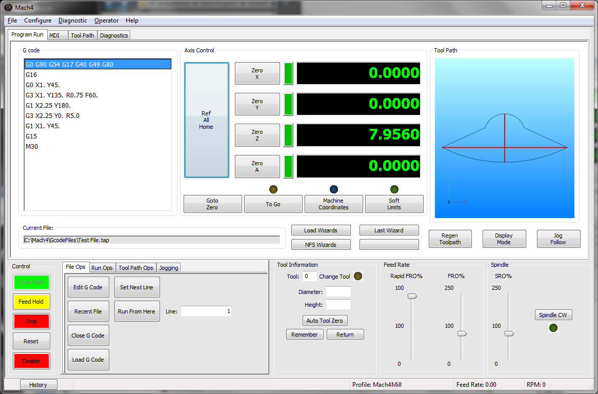
24 24 P a g e Linear and arc moves can be programmed in the polar coordinate mode. When programming arc moves with G02 and G03 use R to specify the arc radius. Example: See figure 7 for the tool path display of the following program. G0 G90 G54 G17 G40 G49 G80 G16 G0 X1.0 Y45.0 G3 X1.0 Y135.0 R0.75 F60.0 Safe start line, absolute mode, XY plane Enable polar coordinate mode Move to radius 1 and 45 from origin Arc move of radius.75, endpoint at G1 X2.25 Y180.0 Linear move to radius 2.25 angle 180 G3 X2.25 Y0 R5.0 Arc move of radius 5., endpoint at G1 X1.0 Y45.0 Linear move to radius 1.0, angle 45 G15 G0 G53 Z0.0 Disable polar coordinate mode Z axis to machine zero TABLE 20 Radius Angle FIGURE 7 TOOL PATH OF POLAR COORDINATE MODE EXAMPLE Figure 15-1: Tool path of polar coordinate mode example
25 P a g e 25 G17/G18/G19 Plane Selection: Arcs, circles and drill cycles require the selection of a plane. The three axes X, Y and Z define three available planes XY, ZX, and YZ, see figure 8. The third axis defines the top of the plane, this axis is also known as the normal see figure 9. Selection of a plane is done by specifying one of three G codes: G17 for XY, G18 for ZX and G19 for YZ. These are modal G codes and will stay active until another plane is selected or the system is reset. The default plane selection is G17. All arc and circular motion will take place on a single plane. Direction of motion, clockwise or counterclockwise, is as viewed from the normal direction, see figure 9. Canned drill cycles also require the selection of a plane. In this case all hole positions will be located in the selected plane and the normal axis will be the drilling axis. For example in the XY plane the Z axis is the drilling axis. Figure 17-1: Planes FIGURE 8 PLANES

26 26 P a g e Axis 3 + Direction (Normal) Look at plane from normal direction Axis 2 + Direction Axis 1 + Direction Figure 17-2: Plane orientation FIGURE 9 PLANE ORIENTATION G20/G21 Unit selection: Programming units are selected using G20 for inch and G21 for millimeter. Use these G codes to specify the units in the program only; the setting will not affect Mach DRO s, configuration settings, or offsets. G28 Zero Return: This function is used to send one or more axes to the home position via an intermediate point. Exercise caution when using this function. If not fully understood the resulting motion may differ greatly from what is expected. When used correctly the intermediate point can be useful for avoiding obstacles in the way of a direct path to the home position, see figure 10.
27 P a g e 27 Z Machine Home Y G0 G91 G28 Y0.0 Z1.0 or G0 G90 G28 Y-2.0 Z0.5 G0 G91 G28 Y0.0 Z0.0 or G0 G90 G53 Y0.0 Z0.0 Tool Z Fixture Zero Y Work Piece Start point Y-2.0, Z-0.5 FIGURE 10 ZERO RETURN VIA INTERMEDIATE POINT Format: G28 X Y Z A B C This is not a modal code and will only be active in the block in which it is specified. Following the G28 are the axes to be sent home. For example, to send the Z axis back to the home position program: G28 Z0. The value specified with the axis letter specifies the intermediate point. Look at an example program: G0 G90 G54 G17 G40 G49 G80 G0 X1.0 Y.5 Z1.0 G28 Z0.0 Safe start line Rapid position to point Send Z axis home via point Z0 Reading through the program there is a safe start up block that sets the machine to absolute position mode. The next line causes the machine to move to the point X1, Y.5, Z1. in the coordinate system set by the G54 fixture offset. Now for the G28 block. This line of code, G28 Z0, gives instructions to send the Z axis to the home position via the point Z0. The motion will be as follows: First the Z axis will plunge to the point Z0 then return to home. If not intended this motion could result in a
28 28 P a g e broken tool or scrapped part. To avoid this unintended motion the common programming format is as follows: G91 G28 Z0 In this case the intermediate point is an incremental move of 0 inches resulting in no motion before the Z axis returns home. G30 2 nd, 3 rd, 4 th Zero Return: G30 functions the same way as G28, moving the machine to a zero return point via an intermediate point. However, instead of sending the machine to the home position, G30 movement ends at a user definable 2 nd, 3 rd, or 4 th zero return point, specified by P2, P3, or P4 respectively. If P is omitted the 2 nd zero return point is selected. This is handy for tool changers that are not located at the home position or any number of other applications. Format: G30 P X Y Z A B C The 2 nd zero return point is defined by # variables as follows: Axis P2 # Variables P3 # Variables P4 # Variables X Y Z A B C TABLE 22 The position values in the # variables can be set in a program or in MDI mode. G31/G31.X Probe function: Also known as skip function, G31 allows the use of part and tool probes. Multiple probes can be used, G31 for probe 1, G31.1 probe 2, G31.2 probe 3 and G31.3 probe 4. Motion is defined along linear axes, in a similar format to G01, with a feed rate. Format: G31 X Y Z F
29 P a g e 29 The machine will move toward the specified end point, at the same time it is looking for the probe input to be activated. When the probe input is activated the current position is recorded to # variables according to the table below and motion is stopped. The recorded position can then be used to calculate tool offsets, work offsets, measure parts, etc. Axis G31 # Variables G31.1 # G31.2 G31.3 X Y Z A B C TABLE 23 G32 Threading: It is possible to cut threads using a spindle to rotate the work piece and a non rotating threading tool. Equal lead straight, tapered and scroll threads can be cutting using this command. Spindle speed feedback from an encoder, index pulse, tachometer or other device is required for this operation. The syncing of the feed axis to the spindle speed creates an accurate thread; however, axis acceleration can cause variations in the thread lead especially at the start and end of the thread. The compensate program a slightly longer thread to give the axis time to accelerate. The amount of extra thread length will vary based on machine specifications. Changes in spindle speed and feed rate will impact thread quality and accuracy. Using constant surface speed mode can also result in variations in thread lead when cutting tapered or scroll threads, use G97 constant RPM mode instead. During the threading move the spindle speed and feed rate overrides will be disabled and the machine will run at 100%. Feed hold will be delayed, if pressed the machine will stop at the end of the threading move. Format: G32 X Y Z F The G32 threading cycle is a single linear move synced to the spindle speed. F specifies the lead or pitch of the thread. For example a 20 TPI thread would have a pitch of.05 inches, so program F.05. By default the movement is basic linear move
30 30 P a g e with synced feed rate. Machine builders and advanced users have the added option to create custom M codes to specify the feed vector to create custom threads. Example: Thread a ¼-20 rod held in the spindle, 1 length of thread. G0 G90 G54 G18 G40 G49 G80 G0 X0.3 Y0.0 Z0.1 G97 S1000 M3 G0 X0.22 G32 X0.22 Z-1.0 F.05 G0 X0.3 Safe start line Rapid position Start spindle at 1000 RPM Move to start position for rough Cut straight thread Retract X axis Z0.1 Retract Z axis X0.21 Move to start position for finish G32 X0.21 Z-1.0 F.05 G0 X0.3 Cut straight thread Retract X axis Z0.1 Retract Z axis G53 Z0.0 M5 Z home and stop spindle TABLE 24 Threads can also be cut with a taper by adding the proper end point. Example: Cut same thread as previous example with 0.03 taper.
31 P a g e 31 G0 G90 G54 G18 G40 G49 G80 G0 X0.3 Y0.0 Z0.1 G97 S1000 M3 G0 X0.22 G32 X0.25 Z-1.0 F.05 G0 X0.3 Safe start line Rapid position Start spindle at 1000 RPM Move to start position for rough Cut tapered thread Retract X axis Z0.1 Retract Z axis X0.21 Move to start position for finish G32 X0.24 Z-1.0 F.05 G0 X0.3 Cut tapered thread Retract X axis Z0.1 Retract Z axis G53 Z0.0 M5 Z home and stop spindle TABLE 25 Threads can also be cut with a taper by adding the proper end point. Example: Cut same thread as previous example with 0.03 taper. Straight thread Tapered thread Scroll thread FIGURE 11 BASIC THREAD TYPE G40 Cutter Compensation Cancel: Cancels the cutter compensation mode. Figure 32-1: Basic thread types G41/G42 Cutter Compensation Left/Right: Enables cutter compensation to the left (G41) or right (G42) of the cutter path by an amount specified in an offset selected by D. Format: G1 G42 D X Y Z F For detailed information see the cutter compensation section of this manual.
32 32 P a g e G43/G44 Tool Length Offset: Activates a tool length offset selected with H. When activated the position DROs will be updated to display the position of the program point of the tool, generally the tip. The tool offset can be applied in the positive direction with G43 or in the negative direction with G44. Generally G43 will be used to apply the tool offset. There are a number of ways of touching off a tool and determining the offset value, see tool offsets in the operation manual for more details, but they are all called and applied the same way. Format: G43 H X Y Z If axis positions are specified in the same block as G43 the machine will move to the commanded point. If the axes are omitted there will be no motion. G49 Tool Length Offset Cancel: Cancels the tool length offset. If no motion is commanded in the G49 block there will be no motion of the machine. G50 Scaling Cancel: Cancels scaling. G51 Scaling/Mirroring Function: When activated the scaling function multiplies all commanded positions by the specified scale factor. The DROs and offsets are not affected, but motion commanded from a program or the MDI screen is affected. Format: G51 X Y Z A B C Specify the axis to be scaled and the desired scale factor. For example: G0 G90 G54 G17 G40 G49 G80 Safe start line G0 X4.0 Y0.0 Z1.0 Rapid position to point (X position is 4.) G51 X2.0 Activate scaling on X axis (scale factor = 2) G0 X5.0 Rapid position to point (X position is 10.) G50 Cancel Scaling G0 X5.0 Rapid position to point (X position is 5.) TABLE 26
33 P a g e 33 When scaling is active position moves will be calculated by multiplying the commanded position by the scale factor. In the example above the scale factor on the X axis is set to 2, then a move to X5. is commanded. The actual end position of this move will be 5 * 2 = 10. So the X axis moves to 10. Exercise caution when using scaling, the results can be unpredictable depending on program complexity. For example if G52 X2 Y4 is programmed followed by an arc move in the XY plane, the arc will NOT be scaled 2x in the X axis and 4x in the Y axis to obtain an ellipse. The start and end positions will be as expected, but the motion from one to the other may not be. Check and double check the tool path display before running the program. To mirror a program, enter a negative scale value. For example: G0 G90 G54 G17 G40 G49 G80 Safe start line G0 X4.0 Y0.0 Z1.0 Rapid position to point (X position is 4.) G51 X-1.0 Mirror X axis (scale factor = 1) G0 X5.0 Rapid position to point (X position is -5.) G50 Cancel Scaling G0 X5.0 Rapid position to point (X position is 5.) TABLE 27 G52 Local Coordinate System Shift: The local coordinate system setting is a programmable work shift. The setting is global; the entire system is shifted by the specified values. Every fixture offset will be affected, although the actual fixture offset values will not be changed. Format: G52 X Y Z A B C To activate a local coordinate system with G52 use the above format. Setting of a local coordinate system is just like setting a fixture offset. In the G52 block specify the desired axes to set, and the value of the shift. For example (see figure 12 for the tool path):
34 34 P a g e G0 G90 G54 G17 G40 G49 G80 G0 X-4.0 Y0.0 Z1.0 Safe start line Rapid position to point G12 I2.0 F30.0 Cut circle with radius 2.0 G52 X7.0 Local Coordinate system active, X offset = 7 G0 X-4.0 Y0.0 Z1.0 Rapid to same start point G12 I2.0 F30.0 Cut same circle with radius 2.0 G52 X0.0 Local coordinate system cancelled TABLE 28 FIGURE 12 EXAMPLE PROGRAM TOOL PATH Figure 52-1: Example program tool path. Once set, the setting will remain until cancelled by another G52 or the system is reset. As in the example above, a local coordinate system can be cancelled by specifying the axis with a value of zero. This effectively sets the local coordinate system shift to zero, giving it no effect. G53 Machine Coordinate System: Although the majority of machine positioning will take place in a user created coordinate system it is sometimes beneficial to program positions in the machine coordinate system. G53 is a non-modal, only active for the block in which it is specified, G code that allows the user to make positioning moves in the machine coordinate system. This can be useful for moving to a load/unload position at the end of a program or moving to a tool
35 P a g e 35 change location in a tool change macro. This is also a much safer way to move back to the machine home position, G53 X0 Y0 Z0, than using G28 as there is no intermediate position to be concerned with. Format: G53 X Y Z A B C G0 G90 G54 G17 G40 G49 G80 G0 X4.0 Y0.0 Z1.0 G53 Z0.0 G53 X10.0 Y0.0 Safe start line Rapid position in G54 Body of program Return directly to Z home position Move to load/unload position TABLE 29 In the example above, the last two positioning moves are made in the machine coordinate system. These two blocks could be the same for every program in this machine. G54-G59 Fixture Offset: Used to select the active fixture offset in a program. The fixture offset will stay active until another is called or the system is reset. It is possible to use multiple fixture offsets in a single program. G54.1 Additional Fixture Offsets: Additional fixture offsets are provided for users with many fixtures/parts/ setups. There are 248 additional offsets available. Format: G54.1 P P specifies the number of the additional offset, 1 thru 248. Previous version of Mach use G59 P7, P8 and so on. These legacy offsets can still be used in place of the G54.1. G59 P7 = G54.1 P1, G59 P8 = G54.1 P2, and so on. G54.1 is more consistent with industry machines. Please see the fixture offset section of this manual for more detail on setting up fixture offsets. G60 Unidirectional Approach: In cases where mechanical backlash causes positioning errors unidirectional approach can be used to increase accuracy. G60 is
36 36 P a g e a non-modal code, when specified in a movement block motion will move to the end point from a parameter defined distance and direction, see figure 13. The distance and direction of the approach movement is specified by setting values in # variables as shown in the following table: Axis # Variable X 5440 Y 5441 Z 5442 A 5443 B 5444 C 5445 TABLE 30 Format: G60 G0/G1 X Y Z When unidirectional approach is used in a drill cycle the Z axis motion is not affected. G76 and G87 boring cycles have a tool shift that is also not affected by the G60 unidirectional approach.
37 P a g e 37 Y 1 Position to start point, X2.0, Y0.0 2 Move to X0.0 with unidirectional approach X End point Start point G00 G90 G54 G17 G40 G49 G80 G0 X2.0 Y0 Z1. S1000 M3 G60 X0 G81 Z-0.5 F20. G60 Y-1.0 G60 X1.0 G60 X1.5 Y-1.5 Note: Example assumes X and Y unidirectional approach parameters are set to positive values Approach distance (X) 3 Move to Y-1.0 with unidirectional approach Start point End point Approach distance (Y) 4 Move to X1.0 with unidirectional approach Start point End point Approach distance (X) 5 Move to X1.5, Y-1.5 with unidirectional approach Start point End point Approach distance (Y) Figure 60-1: Unidirectional approach. Approach distance (X) FIGURE 13 UNIDIRECTIONAL APPROACH G61 Exact Stop Mode: In exact stop mode the machine will decelerate to a complete stop at the end of each commanded move, see figure 5. This is a modal code, once activated it will remain on until canceled. For sharp corners and simple positioning this mode works well. However, when the code gets more complex, or in side milling with arcs, the exact stop mode will produce jerky motion and witness marks on the work piece. For most milling jobs use G64. G64 Constant Velocity Mode: In constant velocity mode Mach will try to maintain feed rate even around sharp corners. As a result sharp corners will be slightly rounded and the machine may never reach the programmed point before a direction change. The magnitude of these position errors will be determined by the acceleration capability of the machine and the programmed feed rate. In most cases the error will be too small to notice or affect part function. Cutting will be faster and smoother with better finishes and no witness marks from stopping. This
38 38 P a g e will be the active mode for the majority of machining time. It is modal and will be active until exact stop mode is activated. G65 Macro Call: Macros work like subprograms (see M98 on page 78) but allow values to be passed from the main program in the form of local variables. Macro programs can use these local variables passed to it to change part dimensions, select features, adjust feed rates, or anything else the user could need to change. Format: G65 P A B C The desired program number to be called is specified by P. The remaining arguments are determined by the macro program being called. The values of these arguments will be passed to local variables for use in the macro program. The available arguments and corresponding variables are shown in the table below. Address Variable Address Variable Address Variable A #1 I #4 T #20 B #2 J #5 U #21 C #3 K #6 V #22 D #7 M #13 W #23 E #8 Q #17 X #24 F #9 R #18 Y #25 H #11 S #19 Z #26 TABLE 31 The G65 macro call is non modal and has no option for repeating, the macro subprogram will be run only once per G65 call. For more information on macro programming and the availability and use of # variables see the Mach4 Macro Programming Guide. G66 Macro Modal Call: Sometimes it is useful to run the same macro in different positions (similar to drilling canned cycles) or with different parameters. G66 is a modal macro call, the macro is called and values passed in the same way as G65, but G66 remains active until cancelled. The block(s) following the G66 can contain new positions and variables to run the macro again.
39 P a g e 39 Format: G66 P A B C A B C G67 More information on macro programming is available in the Mach4 Macro Programming Guide. G67 Macro Modal Call Cancel: Cancels the macro modal call. G68 Coordinate System Rotation: It is possible to rotate a program around a specified point using the coordinate system rotation command. It is specified as follows: Format: G68 X Y R The command is only available in the XY (G17) plane and is modal. X and Y specify the point around which the program will be rotated, and R specifies the angle. A positive value for R will rotate the program counter clockwise when looking at the plane from the positive direction. Once the rotation command is given, all command moves will take place in this rotated system. In effect, the X and Y axes of the machine will rotate the amount specified by R. G0 G90 G54 G17 G40 G49 G80 G0 X0.0 Y0.0 Z1.0 G68 X0.0 Y0.0 R45.0 Safe start line Rapid position to point Rotate 45 counter clockwise about X0, Y0 G0 X1.0 Rapid position to X1. G69 Cancel rotation TABLE 32 In the example above, the machine will move to X0, Y0 then initiate the coordinate rotation of 45. The next move is a purely X axis move to X1. However, because the coordinate system has been rotated the current X axis is actually 45 from the machine actual X axis. When the move takes place both X and Y axes will move to
40 40 P a g e the programmed point. In this case the DROs will read X.7071 and Y See figure 14. +Y Y.7071 X(Rotated) X X FIGURE 14 COORDINATE SYSTEM ROTATION (G68 X0 T0 R45) Figure 68-1: Coordinate system rotation (G68 X0 Y0 R45) The coordinates X.7071 and Y.7071 can be proven using simple geometry or trigonometry functions. Coordinate system rotation is useful in many applications. Combined with a part probe the function can provide a lot of power and accuracy. When probing a part to find its location, it is also possible to determine if the part is clamped square to the axes or if it is oriented at some angle. If the part is skewed at an angle it can be automatically compensated for, resulting in higher quality parts. G69 Coordinate System Rotation Cancel: Cancels a coordinate system rotation command. The machine returns back to normal function. G73-G89 Canned Cycles: Canned cycles are special G codes used to simplify programming. See the Canned Cycles section of this manual for detailed information.
41 P a g e 41 G73 High Speed Peck G73 X_ Y_ Z_ R_ Q_ F_ G74 Reverse Tapping G74 X_ Y_ Z_ R_ F_ G76 Fine Boring G76 X_ Y_ Z_ R_ I_ J_ P_ F_ G80 Canned Cycle Cancel G80 G81 Drilling G81 X_ Y_ Z_ R_ F_ G82 Spot Face G82 X_ Y_ Z_ R_ P_ F_ G83 Deep Hole Peck Drilling G83 X_ Y_ Z_ R_ Q_ F_ G84 Tapping G84 X_ Y_ Z_ R_ F_ G85 Boring, Retract at Feed, Spindle On G85 X_ Y_ Z_ R_ F_ G86 Boring, Retract at Rapid, Spindle Off G86 X_ Y_ Z_ R_ F_ G87 Back Boring G87 X_ Y_ Z_ R_ I_ J_ F_ G88 Boring, Manual Retract G88 X_ Y_ Z_ R_ P_ F_ G89 Boring, Dwell, Retract at Feed, Spindle On G89 X_ Y_ Z_ R_ P_ F_ TABLE 33 G90/G91 Absolute/Incremental Position Mode: In absolute position mode, the machine will move to the commanded position in the active user coordinate system. Example: Write a program to move to the hole positions in figure 15 in absolute position mode. Assume the machine starts at position X0, Y0, end the program at X0, Y0. FIGURE 15 HOLE PATTERN EXAMPLE
42 42 P a g e G0 G90 G54 G17 G40 G49 G80 G90 G0 X1.0 Y-1.0 Safe start line Absolute position mode Rapid to 1 st hole X2.0 Rapid to 2 nd hole X3.0 Rapid to 3 rd hole X0.0 Y0.0 Rapid back to 0, 0 TABLE 34 In incremental position mode, commanded moves are interpreted as distance and direction from the current position. A command of X1 will move 1 in the positive direction, NOT necessarily to the point X1 in the user coordinate system. Example: Write a program to move to the hole positions in figure 15 in incremental position mode. Assume the machine starts at position X0, Y0, end the program at X0, Y0. G0 G90 G54 G17 G40 G49 G80 G91 G0 X1.0 Y-1.0 Safe start line Incremental position mode Rapid to 1 st hole X1.0 Rapid to 2 nd hole X1.0 Rapid to 3 rd hole X-3.0 Y1.0 Rapid back to 0, 0 TABLE 35 Compare this to the program from G90. Because the starting point is X0, Y0 in both examples the move to the 1 st hole is the same. However, if the machine started at X1, Y1 the absolute position program would still be correct, the incremental program would be shifted by the start location. For this reason it is important to ensure the proper mode is enabled for the program in use. A good safe start line will always contain a G90 or G91. These G codes are modal and will stay active until the other is specified.
43 P a g e 43 G90.1/G91.1 Absolute/Incremental Arc Center Mode: This setting affects arcs when programmed in the I, J, K format. In absolute arc center mode the I, J, K values designate the position of the arc center in the user coordinate system. In incremental arc center mode the I, J, K values designate the distance and direction to the arc center from the start point. See figure 2 for a graphical description. Work Zero Y X J (Abs) I (Abs) I (Inc) J (Inc) Start Point R Figure 2-1: Path of tool point in circular and helical interpolation (G02). FIGURE 2 PATH OF TOOL POINT IN CIRCULAR AND HELICAL INTERPOLATION (G02) Example: Program an arc centered at 1.0, 0.0 in the XY plane with radius 2. Start point at 3.0,0.0 and sweep 90 degrees counter clockwise. Program two times, once in incremental arc center mode and once in absolute arc center mode.
44 44 P a g e G0 G90 G54 G17 G40 G49 G80 Safe start line G91.1 Incremental arc center mode T1 M6 S2500 M3 G0 X3.0 Y0.0 G43 H1 Z.5 G1 Z0.0 F10.0 G3 X1.0 Y2.0 I-2.0 J0.0 F10.0 G0 Z.5 G0 G53 Z0.0 Tool change Start spindle Position to X and Y start point Activate tool offset 1 and move to Z rapid plane Z plunge at feed rate Arc move Retract Z to rapid plane Return Z to home TABLE 36 G0 G90 G54 G17 G40 G49 G80 Safe start line G90.1 Absolute arc center mode T1 M6 S2500 M3 G0 X3.0 Y0.0 G43 H1 Z.5 G1 Z0.0 F10.0 G3 X1.0 Y2.0 I1.0 J0.0 F10.0 G0 Z.5 G0 G53 Z0.0 Tool change Start spindle Position to X and Y start point Activate tool offset 1 and move to Z rapid plane Z plunge at feed rate Arc move Retract Z to rapid plane Return Z to home TABLE 37 Notice the difference in the I values of the example programs. Both programs will produce the same arc.
45 P a g e 45 G92 Local Coordinate System Setting: The coordinate system can be set by issuing G92 in the program. This function differs from G52 (Local Coordinate System Shift) in the way that it is specified. While G52 is specified with shift values, G92 is specified with the desired axis position. The affect is global and should be used with caution. Format: G92 X Y Z A B C Using the above format specify a value for the desired axis. When G92 is specified the position DRO s are updated to the values specified. The local coordinate system setting will be cancelled when a G92.1 is specified or the system is reset. G0 G90 G54 G17 G40 G49 G80 G0 X4.0 Y0.0 Z1.0 Safe start line Rapid move, current position X4, Y0, Z1 G92 X1.0 Y2.0 Z3.0 Set local coordinate system, current position X1, Y2, Z3 G92.1 Cancel local coordinate system, current position X4, Y0, Z1 TABLE 38 G92 was used for fixture offset setting before fixture offsets were available. It is recommended that the fixture offsets be used instead of using G92. The offset amount of the G92 setting is not immediately known by the user, because of this the results can be unpredictable when fixture offsets and G92 are combined. G93 Inverse Time Feed: Inverse time feed is most commonly used for machine movement containing at least one rotary axis, however that is not the only application. Instead of specifying a velocity a time to complete the movement is specified. The following formula is used to determine F: F = 1 time (min) = feedrate (units min) distance (units) When inverse time feed is active an F word is required in every block of code containing a feed move.
46 46 P a g e G94 Feed Per Minute: Most common feed rate setting. Specify the desired feed rate in units/minute. In this mode the feed rate is modal and not required in all feed move blocks. G95 Feed Per Revolution: In mills the feed per revolution setting is most commonly used for tapping cycles. In this mode the feed rate is specified in units/revolution of the spindle. In the case of tapping the feed rate can be set as the pitch of the tap. For every revolution of the spindle the machine will move the specified units. Feed per rev mode requires RPM feedback from the spindle. G96 Constant Surface Speed: Spindle speed can be specified two ways. One is constant surface speed. In this mode Mach will try to keep the surface speed constant based on cutting diameter. Surface speed is specified in surface units per minute. In the inch mode this is surface feet per minute, in millimeter mode it is surface meters per minute. G97 Constant RPM: In this mode the spindle speed is specified in revolutions per minute. This is the most common setting for milling machines. G98 Initial Point Return: Specifies that a canned cycle end at the initial Z level. The machine will also return to the initial point before a rapid move to the next position. Initial point return is useful for avoiding steps in parts or fixture clamps without adding a significant amount of cycle time. See figure 16. Initial Point G98 G99 Retract Plane (R) Move at feedrate (F) Move at rapid FIGURE Figure : INITIAL Initial AND and R R point POINT return RETURN setting. SETTING
47 P a g e 47 G99 R Point Return: Specifies that a canned cycle end at the programmed R level, see figure 16. When drilling holes in a flat plate, G99 can be used to reduce excessive machine movement decreasing cycle time.
48 48 P a g e 2 CANNED CYCLES G73 High Speed Peck G73 X_ Y_ Z_ R_ Q_ F_ G74 Reverse Tapping G74 X_ Y_ Z_ R_ F_ G76 Fine Boring G76 X_ Y_ Z_ R_ I_ J_ P_ F_ G80 Canned Cycle Cancel G80 G81 Drilling G81 X_ Y_ Z_ R_ F_ G82 Spot Face G82 X_ Y_ Z_ R_ P_ F_ G83 Deep Hole Peck Drilling G83 X_ Y_ Z_ R_ Q_ F_ G84 Tapping G84 X_ Y_ Z_ R_ F_ G85 Boring, Retract at Feed, Spindle On G85 X_ Y_ Z_ R_ F_ G86 Boring, Retract at Rapid, Spindle Off G86 X_ Y_ Z_ R_ F_ G87 Back Boring G87 X_ Y_ Z_ R_ I_ J_ F_ G88 Boring, Manual Retract G88 X_ Y_ Z_ R_ P_ F_ G89 Boring, Dwell, Retract at Feed, Spindle On G89 X_ Y_ Z_ R_ P_ F_ TABLE 39 Canned cycles are used to reduce program complexity. For example peck drilling a 1 inch hole with.1 inch peck depth would use 30 lines of regular code, but with a canned cycle this same hole can be competed in just 2 lines of code. More importantly if multiple holes are required only 1 extra line of code per hole is needed. There are a variety of canned cycles for different hole types including drilling, boring, and tapping. Hole machining cycles all behave similarly and mostly contain the same parameters. The meaning of each parameter can change depending on two settings. The first is the absolute or incremental mode setting (G90/G91) as defined earlier in this manual. The second is the return point selection G98 initial point return or G99 R point return. Plane selection (G17/G18/G19) can also have an effect on hole machining cycles. Positioning will take place in the active plane, and the drilling operation will be on the normal axis. For example in G17 (XY Plane) hole position will be on the XY plane and the drilling axis will be Z. In G18 (ZX Plane) positioning will be on the ZX
49 P a g e 49 plane and the drilling axis will be Y. For the purposes of this manual all examples and definitions will be in the XY plane (G17). The basic format of a canned cycle is as follows: Gcc G98/99 Xxx Yyy ZzzQqq Rrr Ppp Lll Fff Xxn Yyn G80 cc xx yy zz qq rr pp ll ff xn yn Number of the desired canned cycle (i.e. 81, 83, 74, etc) In G90: X position of the center point of the first hole with respect to the current work zero point In G91: Distance and direction along X axis to center point of first hole from the current position In G90: Y position of the center point of the first hole with respect to the current work zero point In G91: Distance and direction along Y axis to center point of first hole from the current position In G90: Z position of bottom of hole with respect to the current work zero point In G91: Distance and direction along Z axis, from point R, to bottom of hole Peck increment if deep hole drilling, always positive Retract plane, retract position between pecks, in G99 mode this is the rapid plane Dwell, in seconds, at bottom of hole Number of repetitions Feed rate Position of nth hole X axis, same rules as applied to xx Position of nth hole Y axis, same rules as applied to yy TABLE 40 Please note that not all arguments will appear in all cycles, and there are a couple special cases that will be discussed.
50 50 P a g e FIGURE 17 EXAMPLE HOLE PATTERN G80 Canned Cycle Cancel: To end a canned cycle a G80 must be called. G80 should be specified on its own line to avoid any unintended movements. For example: G0 G90 G54 G17 G40 G49 G80 T1 M6 S2500 M3 G0 X1.0 Y-1.0 G43 H1 Z.5 G81 G99 X1.0 Y-1.0 Z-1.0 R.25 F10 Safe start line Tool change Start spindle Position to X and Y start point Activate tool offset 1 and move to Z initial Drill cycle start X2.0 Y-1.0 Drill second hole X3.0 Y-1.0 Drill third hole G80 G0 G53 Z0 Canned cycle cancel Return Z to home TABLE 41
51 P a g e Drilling G81 Drilling: This is a straight drilling cycle. The tool simply moves to position, feeds to the bottom of the hole then rapid retracts to either the R point or the initial point. See figure 18 for a graphic of the tool motion. The format is as follows: G81 X Y Z R L F X, Y Position of hole in XY plane Z End point of hole R Retract plane L Number of repetitions F Feedrate Initial Point Retract Plane (R) Move at feedrate (F) Move at rapid Final Hole Depth (Z) FIGURE 18 MOTION Figure 81-1: OF TOOL Motion POINT of tool FOR point G81 for CYCLE. G81 cycle. END End Z POSITION Z position WILL will be BE determined DETERMINED by BY G98/99 G98/G99 setting. SETTING
52 52 P a g e Example: Create the program for the holes shown in 17. G0 G90 G54 G17 G40 G49 G80 T1 M6 S2500 M3 G0 X1.0 Y-1.0 G43 H1 Z.5 G81 G99 X1.0 Y-1.0 Z-1.0 R.25 F10 Safe start line Tool change Start spindle Position to X and Y start point Activate tool offset 1 and move to Z initial Drill cycle start X2.0 Y-1.0 Drill second hole X3.0 Y-1.0 Drill third hole G80 G0 G53 Z0 Canned cycle cancel Return Z to home TABLE 42 G82 Spot Face: Spot face adds the ability to dwell at the bottom of the hole for a specified amount of time. The actual tool motion is the same as a G81 cycle, however with the dwell it is possible to attain better accuracy and finish at the bottom of the hole. This is useful for chamfering, counter boring, and spot facing. The format is as follows: G82 X Y Z R P L F X, Y Position of hole in XY plane Z End point of hole R Retract plane P Dwell L Number of repetitions F Feed rate
53 P a g e 53 Example: Create a chamfering program for the holes shown in figure 17, dwell for.2 seconds. G0 G90 G54 G17 G40 G49 G80 Safe start line T1 M6 Tool change S2500 M3 G0 X1.0 Y-1.0 G43 H1 Z.5 G82 G99 X1.0 Y-1.0 Z-.200 P.2 R.25 F10 Start spindle Position to X and Y start point Activate tool offset 1 and move to Z initial point Spot drill cycle start X2.0 Y-1.0 Drill second hole X3.0 Y-1.0 Drill third hole G80 G0 G53 Z0 Canned cycle cancel Return Z to home TABLE 43 G83 Peck Drilling: Peck drilling is a cycle used for drilling deep holes. The cycle allows for breaking and clearing of chips and better application of coolant by fully retracting the tool from the hole between pecks. This retract move and plunge to previous depth are rapid moves, each peck is a feed move at the specified feed rate. See figure 83-1 for a graphic of the tool motion. The format is as follows: G83 X Y Z Q R L F X, Y Position of hole in XY plane Z End point of hole Q Peck amount R Retract plane L Number of repetitions F Feed rate
54 1 st Peck Nth Peck Last Peck 54 P a g e Initial Point Retract Plane (R) Peck Depth (Q) Move at feedrate (F) Move at rapid Final Hole Depth (Z) FIGURE 19 MOTION OF TOOL POINT FOR G83 CYCLE. END Z POSITION WILL BE DETERMINED BY G98/G99 SETTING Example: Figure 83-1: Motion of tool point for G83 cycle. End Z position will be determined by G98/99 setting. Create the program for the holes shown in figure 17 using a.1 peck depth. Create the program for the holes shown Safe start line T1 M6 S2500 M3 G0 X1.0 Y-1.0 G43 H1 Z.5 G83 G99 X1.0 Y-1.0 Z-1.0 Q.1 R.25 F10 Tool change Start spindle Position to X and Y start point Activate tool offset 1 and move to Z initial point Peck drill cycle start X2.0 Y-1.0 Drill second hole X3.0 Y-1.0 Drill third hole G80 G0 G53 Z0 Canned cycle cancel Return Z to home TABLE 44 G73 High Speed Peck: In materials that produce long stringy chips a high speed peck cycle can be used to break them up. Unlike the G83 cycle that retracts completely out of the hole after each peck, the G73 cycle only retracts.100 inch.
55 1 st Peck Nth Peck Last Peck P a g e 55 See figure 20. This short retract helps to reduce cycle times when a complete retract is unnecessary. The format: G73 X Y Z Q R L F X, Y Position of hole in XY plane Z End point of hole Q Peck amount R Retract plane L Number of repetitions F Feedrate Initial Point Retract Plane (R) Peck Depth (Q) Move at feedrate (F) Move at rapid Final Hole Depth (Z) Figure 73-1: Motion of tool point for G73 cycle. End Z position will be determined by G98/99 setting. FIGURE 20 MOTION OF TOOL PONT FOR G73 CYCLE. END Z POSITION WILL BE DETERMINED BY G98/99 SETTING
56 56 P a g e Example: Create the program for the holes shown in figure 17 using a.025 peck depth. G0 G90 G54 G17 G40 G49 G80 Safe start line T1 M6 S2500 M3 G0 X1.0 Y-1.0 G43 H1 Z.5 G73 G99 X1.0 Y-1.0 Z-1.0 Q.1 R.25 F10 Tool change Start spindle Position to X and Y start point Activate tool offset 1 and move to Z initial point Peck drill cycle start X2.0 Y-1.0 Drill second hole X3.0 Y-1.0 Drill third hole G80 G0 G53 Z0 Canned cycle cancel Return Z to home TABLE Tapping G84 Right Hand Tapping: The tapping cycle is used to create threaded holes using a tap. Tapping requires that the spindle rpm and Z axis feed rate be matched, related by the pitch of the thread being cut. There are two ways to achieve this synchronization of spindle speed and Z axis feed rate. From the programming side it is easier to program the feed rate in units per revolution (G95). In the feed per rev mode the commanded feed rate will be simply the pitch of the thread. Metric threads are classified with the thread pitch, i.e. M8x1.25mm thread has a 1.25mm pitch. Unified threads are classified by threads per inch which requires a bit of calculation to get the pitch, don t worry it s easy. Simply divide 1 inch by the TPI. For a ¼-20 fastener we would calculate 1/20 =.05, this is the pitch. The catch is, to use feed per rev requires some form of rpm feedback from the machine, not every machine will have this. For the machines without feedback the tapping cycle can be programmed in feed per min mode (G94). This method requires a little more math to obtain the correct feed rate based on spindle rpm and pitch of the thread. The equation looks like this: RPM*Pitch=IPM. To tap that
57 P a g e 57 ¼-20 hole at 1500 RPM we first need to calculate the pitch, remember 1/TPI = Pitch, so 1/20=.05. Now we calculate the feed per min as 1500 *.05=75 IPM. It is important to note that if the spindle speed is changed, the feed per minute must also be changed to match. Now that the math is done, check out the format of the code: G84 X Y Z R L F X, Y Position of hole in XY plane Z End point of hole R Retract plane L Number of repetitions F Feed rate The motion of the tapping cycle is straight forward, but does require some additional description. See Figure 21 for a graphic of the tool motion. The movement is very similar to a straight drill cycle, action of the spindle being the major difference. The spindle must be started in the forward direction prior to calling the G84 cycle. The machine will then move to the hole position then the Z axis will move down to the R plane. The Z will feed down to the specified depth then the spindle and Z axis will stop then reverse direction to retract out of the hole. Due to slight variations of spindle speed, feed rate and accelerations in some machines it is recommended that a special tapping head be used. A tapping head allows the tap to float a little bit, compensating for those variations, especially at the bottom of the hole. Changes to feed rate or spindle speed mid cycle can be damaging to the tool and work piece, for this reason the feed rate and spindle speed overrides are disabled. The machine will run at 100% override for the duration of the cycle. Feed hold is also disabled during the cycle. If feed hold is pressed motion will stop at the end of the tapping cycle.
58 58 P a g e Initial Point Retract Plane (R) Spindle FWD Spindle FWD Move at feedrate (F) Move at rapid Final Tap Depth (Z) Spindle REV FIGURE 21 MOTION OF TOOL POINT FOR G84 CYCLE. END Z POSITION WILL BE DETERMINED BY G98/99 SETTING Example: Figure 84-1: Motion of tool point for G84 cycle. End Z position will be determined by G98/99 setting. Create the program to tap the holes shown in figure 2 to a depth of.500 with a 3/8-16 tap using feed/min. 1/16= *.0625=62.50 G90 G54 G17 G40 Safe start line T1 M6 S1000 M3 G0 X1.0 Y-1.0 G43 H1 Z.5 G84 G99 X1.0 Y-1.0 Z-.500 R.25 F62.5 Tool change Start spindle Position to X and Y start point Activate tool offset 1 and move to Z initial point Tapping cycle start X2.0 Y-1.0 Tap second hole X3.0 Y-1.0 Tap third hole G80 G0 G53 Z0 Canned cycle cancel Return Z to home TABLE 46
59 P a g e 59 G74 Left Hand Tapping: Left hand tapping is the same as right hand tapping (G84) except that it will cut left hand threads. The spindle must be started in the reverse direction before calling the G74 cycle. G84.2/G84.3 Right and Left Hand Rigid Tapping: Rigid tapping can be performed on capable machines. As the name implies the tap is held rigidly in the spindle, no tension/compression style tapping holder is required. Holding the tap in this manner requires the machine to have precise control of spindle speed, axis feed, and precise feedback of spindle RPM. The tapping axis will be electronically geared to the spindle RPM. Use G84.2 for right hand tapping and G84.3 for left hand tapping. See figure 21 for a graphic of the motion. Format: G84.2/84.3 X Y Z R P L F J X, Y Position of hole in XY plane Z End point of hole R Retract plane P Dwell in seconds L Number of repetitions F Feedrate J Spindle speed for retract As will other tapping cycles the feedrate and spindle speed overrides are disabled and set to 100% for the duration of the cycle. Feed hold is also no effective until the end of the tapping cycle. Example: Create the program to tap the holes shown in figure17 to a depth of.500 with a 3/8-16 tap using feed/min. Tap at 1000 RPM, retract at 2000 RPM 1/16= *.0625=62.5
60 60 P a g e G0 G90 G54 G17 G40 G49 G80 T1 M6 S1000 M3 G0 X1.0 Y-1.0 G43 H1 Z.5 Safe start line Tool change Start spindle Position to X and Y start point Activate tool offset 1 and move to Z initial point G84.2 G99 X1.0 Y-1.0 Z-.500 R.25 F62.5 J2000 Rigid tapping cycle start X2.0 Y-1.0 Tap second hole X3.0 Y-1.0 Tap third hole G80 G0 G53 Z0 Canned cycle cancel Return Z to home TABLE Boring G76 Fine Boring: The fine boring cycle allows the user to stop the spindle and move the tool away from the wall before retracting. This allows for a rapid retract without leaving a scratch on the wall. G76 X Y Z R I J P L F X, Y Position of hole in XY plane Z End point of hole R Retract plane I X shift distance and direction J Y shift distance and direction P Dwell in seconds L Number of repetitions F Feed rate
61 P a g e 61 Initial Point Retract Plane (R) Move at feedrate (F) Move at rapid Final Hole Depth (Z) Dwell, Stop spindle, Shift amount I and J FIGURE 22 MOTION Figure OF TOOL 76-1: Motion POINTFOR of tool point G76 for CYCLE. G76 cycle. END End Z position POSITION will be WILL determined BE DETERMINED by G98/99 setting. BY G98/99 SETTING After feeding to the bottom of the hole, the machine with pause for the specified dwell time, then the spindle will stop in the orient position before making the shift move defined by I and J. In machines with a spindle orient function called by M19 this will all be automatic. However, many machines are not capable of orienting the spindle so the orientation must be done manually. Make an M code macro program M19.mcs to command a spindle stop and an M0 mandatory program stop. This will allow the operator to manually orient the spindle before the shift move is made. Here is an example of the M19 macro for the manual orient: INSERT MANUAL M19 MACRO PROGRAM HERE TABLE 48
62 62 P a g e Example: Create the program to fine bore the holes shown in figure 2. G0 G90 G54 G17 G40 G49 G80 T1 M6 S2500 M3 G0 X1.0 Y-1.0 G43 H1 Z.5 Safe start line Tool change Start spindle Position to X and Y start point Activate tool offset 1 and move to Z initial point G76 G99 X1.0 Y-1.0 Z-1.0 R.25 I-.025 J0 F10.0 Fine bore cycle, shift X-.025 at X2.0 Y-1.0 Bore second hole X3.0 Y-1.0 Bore third hole G80 G0 G53 Z0 Canned cycle cancel Return Z to home TABLE 49 G85 Boring, Feed rate Retract: G85 is a straight boring cycle, most commonly used for boring or reaming. The retract is at the programmed feed rate with the spindle on. G85 X Y Z R L F X, Y Position of hole in XY plane Z End point of hole R Retract plane L Number of repetitions F Feed rate
63 P a g e 63 Initial Point Retract Plane (R) Move at feedrate (F) Move at rapid Final Hole Depth (Z) FIGURE 23 MOTION Figure OF 85-1: TOOL Motion POINT of tool FOR point G85 for G85 CYCLE. cycle. End END Z position Z POSITION will be WILL determined BE DETERMINED by G98/99 setting. BY G98/99 SETTING Example: Create the program to bore the holes shown in figure 17. G0 G90 G54 G17 G40 G49 G80 Safe start line T1 M6 S2500 M3 G0 X1.0 Y-1.0 G43 H1 Z.5 G85 G99 X1.0 Y-1.0 Z-1.0 R.25F10.0 Tool change Start spindle Position to X and Y start point Activate tool offset 1 and move to Z initial point Boring cycle start X2.0 Y-1.0 Bore second hole X3.0 Y-1.0 Bore third hole G80 G0 G53 Z0 Canned cycle cancel Return Z to home TABLE 50 G86 Boring, Rapid Retract: G86 is a straight boring cycle. Before retracting from the hole the spindle is stopped. The retract is then performed at the rapid rate. This will leave a scratch or multiple scratches where the cutting edges are in contact with the wall. G86 X Y Z R P L F
64 64 P a g e X, Y Position of hole in XY plane Z End point of hole R Retract plane P Dwell in seconds L Number of repetitions F Feedrate Initial Point Retract Plane (R) Move at feedrate (F) Move at rapid Final Hole Depth (Z) Dwell, Spindle Stop Figure 86-1: Motion of tool point for G86 cycle. End Z position will be determined by G98/99 setting. FIGURE 24 MOTION OF TOOL POINT FOR G86 CYCLE. END Z POSITION WILL BE DETERMINED BY G98/99 SETTING Example: Create the program to bore the holes shown in figure 17. G0 G90 G54 G17 G40 G49 G80 Safe start line T1 M6 S2500 M3 G0 X1.0 Y-1.0 G43 H1 Z.5 G86 G99 X1.0 Y-1.0 Z-1.0 R.25F10.0 Tool change Start spindle Position to X and Y start point Activate tool offset 1 and move to Z initial point Boring cycle start X2.0 Y-1.0 Bore second hole X3.0 Y-1.0 Bore third hole G80 G0 G53 Z0 Canned cycle cancel Return Z to home TABLE 51
65 P a g e 65 G87 Back Boring: G87 is a back boring cycle. This is a useful cycle for spot facing, counter boring or chamfering the back side of a part. At the start of the cycle the spindle will be stopped at the orient position and the tool offset from the hole center by the distance and direction defined by I and J. For machines that do not have the ability to orient the spindle, see the M19 macro example in the G76 cycle description. The tool can then be positioned to the R point below the work piece. Once at the R point the tool will be positioned at the hole center and the spindle started to perform the back boring operation. When the specified Z point is reached the machine will orient the spindle, offset by amount I, J and retract back to the initial point. In this cycle the R point will always be below the work piece, not a good point the end the cycle. For that reason this canned cycled will always return to the initial point, it is not possible to specify a G99 R point return. G87 X Y Z R I J P L F X, Y Position of hole in XY plane Z End point of hole R Retract plane I X shift distance and direction J Y shift distance and direction P Dwell in seconds L Number of repetitions F Feed rate Initial Point Spindle orient and shift by I, J Move at feedrate (F) Move at rapid Final Hole Depth (Z) Retract Plane (R) Shift back start spindle Spindle orient and shift by I, J Figure 87-1: Motion of tool point for G87 cycle. End Z position will be determined by G98/99 setting. FIGURE 25 MOTION OF TOOL POINT FOR G87 CYCLE. END Z POSIITON WILL BE DETERMINED BY G98/99 SETTING
66 66 P a g e Example: Create the program to back bore thru holes at the same positions shown in figure 17. Thru depth 1 inch, back bore depth.150 inch. G0 G90 G54 G17 G40 G49 G80 Safe start line T1 M6 S2500 M3 G0 X1.0 Y-1.0 G43 H1 Z.5 Tool change Start spindle Position to X and Y start point Activate tool offset 1 and move to Z initial point G87 G98 X1.0 Y-1.0 Z-0.85 R-1.05 I-.10 F10.0 Back boring cycle start (Shift -.1 in X axis) X2.0 Y-1.0 Bore second hole X3.0 Y-1.0 Bore third hole G80 G0 G53 Z0 Canned cycle cancel Return Z to home TABLE 52 G88 Boring, Manual Retract: This boring cycle features a manual retract. At the bottom of the hole the specified dwell is performed, then the spindle is stopped and the program paused. The operator can then manually retract the tool from the hole. After retracting the tool cycle start is pressed to continue program operation. G88 X Y Z R P L F X, Y Position of hole in XY plane Z End point of hole R Retract plane P Dwell in seconds L Number of repetitions F Feed rate
67 P a g e 67 Initial Point Retract Plane (R) Move at feedrate (F) Move at rapid Manual jog Final Hole Depth (Z) Figure 88-1: Motion of tool point for G85 cycle. FIGURE 26 MOTION OF TOOL POINT FOR G85 CYCLE Example: Create the program to bore the holes shown in figure 17. G0 G90 G54 G17 G40 G49 G80 T1 M6 S2500 M3 G0 X1.0 Y-1.0 G43 H1 Z.5 G88 G99 X1.0 Y-1.0 Z-1.0 R.25F10.0 Safe start line Tool change Start spindle Position to X and Y start point Activate tool offset 1 and move to Z initial point Boring cycle start, pause for manual retract X2.0 Y-1.0 Bore second hole, pause for manual retract X3.0 Y-1.0 Bore third hole, pause for manual retract G80 G0 G53 Z0 Canned cycle cancel Return Z to home TABLE 53 G89 Boring, Dwell & Feedrate Retract: Same function as G85 with the addition of a dwell at the bottom of the hole. G89 X Y Z R P L F X, Y Position of hole in XY plane Z End point of hole
68 68 P a g e R Retract plane P Dwell in seconds L Number of repetitions F Feed rate Initial Point Retract Plane (R) Move at feedrate (F) Move at rapid Final Hole Depth (Z) Dwell (P) FIGURE 27 MOTION OF TOOL POINT FOR G89 CYCLE. END Z POSITON WILL BE DETERMINED BY G98/99 SETTING Example: Create the program to bore the holes shown in figure 17. G0 G90 G54 G17 G40 G49 G80 T1 M6 S2500 M3 G0 X1.0 Y-1.0 G43 H1 Z.5 G89 G99 X1.0 Y-1.0 Z-1.0 R.25 P.250 F10.0 Safe start line Tool change Start spindle Position to X and Y start point Activate tool offset 1 and move to Z initial point Boring cycle start X2.0 Y-1.0 Bore second hole X3.0 Y-1.0 Bore third hole G80 G0 G53 Z0 Canned cycle cancel Return Z to home TABLE 54
69 P a g e 69 3 CUTTER COMPENSATION Cutter compensation provides the user with the ability to adjust the tool path for variations in tool cutter diameter. It can be used in two ways. First, when programming by hand, without the aid of CAM (Computer Aided Manufacturing) software, it is much easier to program the actual part dimensions, part line programming. This saves the programmer for having to calculate to correct path at the center of the tool when the edge is doing the cutting. When given a proper diameter offset, cutter compensation will make the appropriate tool path adjustments to cut the part correctly. Essentially the machine does the math for the programmer. Second, with the more widespread use of CAM systems the tool path is already adjusted for the tool diameter and the part should, in theory, be cut perfectly to size. In practice however, there are many factors that determine the finished size of a machined part, cutter and machine deflection, machine positioning accuracy, cutter diameter variations, etc. Cutter compensation allows for fine tuning the tool path, and adjustment of part dimensions, without having to change the program itself. There are two G codes used to enable cutter compensation. G41 offsets the tool to the left of the tool path and G42 offsets the tool to the right of the tool path. This is only true for positive diameter offset values. If negative offset is specified the offset direction will be reversed, see figure 28. There are two ways to call the offset value with G41 and G42. Format 1: G00/G01 G41/G42 D X Y F Format 2: G00/G01 G41/G42 P X Y F Use D to call a diameter offset from a specific tool offset number. For example, D2 will use the diameter offset value of tool offset number 2. An alternative is to use P. The value specified with P will be the actual offset value. For example, P.05 will offset the tool path.05 to the left or right. Cutter compensation only works on the two in plane axes, so for G17 (XY plane) the X and Y axes are affected by the comp, G18 ZX and G19 YZ.
70 70 P a g e Climb Milling Conventional Milling G40 G40 Work Piece G41 + Offset G42 - Offset Programmed tool path Cutter comp tool path G42 + Offset G41 - Offset Figure 41-1: Cutter compensation offset direction. FIGURE 28 CUTTER COMPENSATION OFFSET DIRECTION There are two types of milling, which style is used determines how the tool should be compensated. The two types are climb milling and conventional milling, see figure 28. Conventional milling is the standard in manual machines, but with CNC it is possible and recommended to climb mill when possible. This manual will assume the tool will always be climb milling. With that assumption if G41 is used for outside features, the profile of a part, then a positive offset will make the part bigger and a negative offset will make the part smaller. For inside features, a hole, G42 will make the hole bigger with a positive offset and smaller with a negative offset, see figure 29. This method tends to make the offset values more intuitive for the operator. If conventional milling is used, this description will be reversed.
71 P a g e 71 Climb milling outside of part: G41 with a positive offset makes part dimensions bigger. Programmed tool path Cutter comp tool path Part Edges Figure 41-2: Cutter compensation OD and ID features. FIGURE 29 CUTTER COMPENSATION OD AND ID FEATURES Climb milling inside of part: G42 with a positive offset makes hole dimensions bigger. Cutter comp should be enabled on a linear lead-in move; an error will be produced if cutter comp is enabled in a block with an arc. If there is a value other than zero in the offset then this lead-in move may not be parallel to the programmed path, see figure 28, 34 and 35. The end point of the start block is the point at a 90 angle to the movement in the next block and at the offset distance. See figure 30 for examples. This linear move must be longer than the offset amount, if it is not there will be an error. Also, if there are any segments of the tool path shorter than the offset amount a gouge is likely, see figure 31. The tool path display in Mach will display the actual tool path with comp, check to make sure there are no gouges or abnormalities before running a part.

72 72 P a g e Programmed tool path Cutter comp tool path Figure 41-3: Cutter compensation start blocks. FIGURE 30 CUTTER COMPENSATION START BLOCKS Gouge Tool Path 1: No cutter comp G00 G90 G54 G17 G40 G49 G80 G0 X0 Y0 Z1. S1000 M3 G1 G41 P0 Y.5 F25. X1.5 Y.6 X2.0 G40 Y1.25 Tool Path 2: Comp radius.05 G00 G90 G54 G17 G40 G49 G80 G0 X0 Y0 Z1. S1000 M3 G1 G41 P0.05 Y.5 F25. X1.5 Y.6 X2.0 G40 Y1.25 Tool Path 3: Comp radius.15 G00 G90 G54 G17 G40 G49 G80 G0 X0 Y0 Z1. S1000 M3 G1 G41 P0.15 Y.5 F25. X1.5 Y.6 X2.0 G40 Y1.25 Figure 41-4: Cutter compensation radius and gouge. FIGURE 31 CUTTER COMENSATION RADIUS AND GOUGE Figure 31 shows three tool paths generated by the same program with different cutter compensation offset values. The gouge is created when an offset value greater than the step of.10 is input. When this happens the compensated tool path
Mach4 CNC Controller Mill Programming Guide Version 1.0
 Mach4 CNC Controller Mill Programming Guide Version 1.0 1 Copyright 2014 Newfangled Solutions, Artsoft USA, All Rights Reserved The following are registered trademarks of Microsoft Corporation: Microsoft,
Course outline. Know Your Machine From A Programmer s Viewpoint 11 If you ve had experience with conventional (non-cnc) machine tools 11
 machine tools 11") Course outline Know Your Machine From A Programmer s Viewpoint 11 If you ve had experience with conventional (non-cnc) machine tools 11 Machine Configurations 13 Vertical machining centers 13 C-frame style
Course outline Know Your Machine From A Programmer s Viewpoint 11 If you ve had experience with conventional (non-cnc) machine tools 11 Machine Configurations 13 Vertical machining centers 13 C-frame style
CNC Programming. Lecture 25. Engineering 475 Automated Production Systems
 CNC Programming Lecture 25 Engineering 475 Automated Production Systems Information Needed by a CNC Machine 1. Preparatory Information: units, incremental or absolute positioning 2. Coordinates: X,Y,Z,
G and M Programming for CNC Milling Machines. Denford Limited Birds Royd Brighouse West Yorkshire England HD6 1NB Tel: +44 (0) 1484 712264
 1484 712264") COMPUTERISED MACHINES AND SYSTEMS G and M Programming for CNC Milling Machines Denford Limited Birds Royd Brighouse West Yorkshire England HD6 1NB Tel: +44 (0) 1484 712264 G AND M Fax: PROGRAMMING +44
COMPUTERISED MACHINES AND SYSTEMS G and M Programming for CNC Milling Machines Denford Limited Birds Royd Brighouse West Yorkshire England HD6 1NB Tel: +44 (0) 1484 712264 G AND M Fax: PROGRAMMING +44
Proficiency Test For Machining Center
 Proficiency Test For Machining Center Name: Date: Section One: General CNC Questions 1) The spindle speed for a particular tool in a program is incorrect and you wish to reduce it. The kind of CNC word
ME 1355 CAD/CAM LABORATORY CNC MILLING PROGRAM. Study of G Codes and M Codes to Write Manual Part Programming for Fanuc Control Systems
 ME 1355 CAD/CAM LABORATORY CNC MILLING PROGRAM Ex.No.1 Study of G Codes and M Codes to Write Manual Part Programming for Fanuc Control Systems PREPARATORY FUNCTION ( G CODES ) The preparatory functions
G10 Data Setting Command
 G10 Data Setting Command Though it s barely mentioned in most basic CNC courses, the G10 command is an extremely important basic CNC feature It allows you to input data from within CNC programs This data
3300M CNC Control Editing, Part Programming and Running simple program
 3300M CNC Control diting, Part Programming and Running simple program Writen by Robin Baker F2 dit to enter editor. F1 F2 F3 F4 F5 F6 F7 F8 F9 Teach Draw Drill Pocket Mill Tool Calc Sub Misc xit Dimension
Mill Series Training Manual. Haas CNC Mill Programming
 Haas Factory Outlet A Division of Productivity Inc Mill Series Training Manual Haas CNC Mill Programming Revised 042814 (Printed 04-2014) This Manual is the Property of Productivity Inc The document may
GSK928MA Milling Machine CNC System. User Manual. GSK CNC Equipment
 GSK928MA Milling Machine CNC System User Manual GSK CNC Equipment The operating manual describes all matters concerning the operation of the system in detail as much as possible. However, it is impractical
5. Tutorial. Starting FlashCut CNC
 FlashCut CNC Section 5 Tutorial 259 5. Tutorial Starting FlashCut CNC To start FlashCut CNC, click on the Start button, select Programs, select FlashCut CNC 4, then select the FlashCut CNC 4 icon. A dialog
CNC 8055 / CNC 8055i SELF-TEACHING MANUAL ( TC OPTION) (REF 0607) (Ref 0607)
 (REF 0607) (Ref 0607)") CNC 8055 / CNC 8055i (REF 0607) SELF-TEACHING MANUAL ( TC OPTION) (Ref 0607) All rights reserved. No part of this documentation may be copied, transcribed, stored in a data backup system or translated
CNC 8055 / CNC 8055i (REF 0607) SELF-TEACHING MANUAL ( TC OPTION) (Ref 0607) All rights reserved. No part of this documentation may be copied, transcribed, stored in a data backup system or translated
Easy Machining Center Setup
 White Paper Document No. MWA-072-EN_01_1404 April 2014 Easy Machining Center Setup Using FANUC s Direct Input of Workpiece Origin Setting Measured and Tool Length Measurement features to easily establish
FAGOR CNC 8055 ia-mc Control
 FAGOR CNC 8055 ia-mc Control The Fagor 8055 i/a-mc CNC control combines value & reliability with a featured packed modular control. This control was built for the shop environment with a rugged keyboard
Radius Compensation G40, G41, & G42 (cutter radius compensation for machining centers, tool nose radius compensation for turning centers)
") Radius Compensation G40, G41, & G42 (cutter radius compensation for machining centers, tool nose radius compensation for turning centers) These features are commonly well covered in most basic CNC courses.
Radius Compensation G40, G41, & G42 (cutter radius compensation for machining centers, tool nose radius compensation for turning centers) These features are commonly well covered in most basic CNC courses.
Summary Of GCODE Commands By Category (HTT0196)
") Summary Of GCODE Commands By Category (HTT0196) SET UP COMMANDS CODE COMMAND FORMAT PURPOSE PAGE # F Feed Speed Fn Designates feed rate, or rate 05 of movement, of the axes. G4 Dwell Time G4/d Specifies
Summary Of GCODE Commands By Category (HTT0196) SET UP COMMANDS CODE COMMAND FORMAT PURPOSE PAGE # F Feed Speed Fn Designates feed rate, or rate 05 of movement, of the axes. G4 Dwell Time G4/d Specifies
Presentation on CNC MACHINES. By: Hafiz Muhammad Rizwan
 Presentation on CNC MACHINES By: Hafiz Muhammad Rizwan WELCOME CNC Machines What is a CNC Machine? CNC : Computer Numerical Control Conventionally, an operator decides and adjusts various machines parameters
CNCTRAIN. Cnc Simulation Systems, 1985,2009
 CNCTRAIN Cnc Simulation Systems, 1985,2009 p2 Table of Contents CNCTRAIN 4 Introduction 4 CNCWRITE 6 CNCwrite Milling Example 6 CNCwrite Turning Example 7 CNCwrite Slots on Circle Example 8 G and M Code
CNC Applications. Tool Radius Compensation for Machining Centers
 CNC Applications Tool Radius Compensation for Machining Centers Why Cutter Diameter Compensation? When machining finished surfaces with the side of a milling cutter (generally called profiling), the accuracy
SINUMERIK 810/840D DIN Programming for Milling
 SINUMERIK 810/840D DIN Programming for Milling Training Manual Edition 2008.01 Training Documentation SINUMERIK 810/840D Operating and Programming DIN - Milling Valid for: Control SINUMERIK 810/840D Edition
Lead Screw Backlash and Mach3, version 2
 Lead Screw Backlash and Mach3, version 2 By R. G. Sparber Copyleft protects this document. 1 This article looks closely at backlash and then explains how to measure it. The resulting numbers are used in
CNC Applications. Introduction to Machining Centers
 CNC Applications Introduction to Machining Centers Machining Centers A machining center is simply a CNC milling machine with an automatic tool changer and an enclosure. There are a number of different
TL-Series Sub-Spindle Operator s Addendum
 3 4 5 11 9 TL-Series Sub-Spindle Operator s Addendum 2 1 12 10 6 7 8 20HP VECTOR DUAL DRIVE LIVE TOOLING SUB SPINDLE 2008 Haas Automation, Inc. 96-0037 rev L 9/08 1 1. Introduction Specific M codes are
Computer-Aided Numerical Control (CNC) Programming and Operation; Lathe Introduction, Advanced Mills
 Programming and Operation; Lathe Introduction, Advanced Mills") 1 of 6 9/9/2014 3:59 PM I. Catalog Information Credit- Degree applicable Effective Quarter: Fall 2014 MCNC 75B Computer-Aided Numerical Control (CNC) Programming and Operation; Lathe Introduction, Advanced
1 of 6 9/9/2014 3:59 PM I. Catalog Information Credit- Degree applicable Effective Quarter: Fall 2014 MCNC 75B Computer-Aided Numerical Control (CNC) Programming and Operation; Lathe Introduction, Advanced
Queensborough Community College NSF Tech ASCEND
 Queensborough Community College NSF Tech ASCEND Computer Numerical Control (CNC) Component Student Manual Prepared by Prof. Joseph Goldenberg, MET&DD Department 2003 Edition Table of Contents Introduction
Sample. CNC Programming product family... CNC Programming: Basics & Tutorial Textbook. & CNC Programming: Reference Book. CNC Programming: Workbook
 CNC Programming product family... CNC Programming: Basics & Tutorial Textbook CNC Programming: Reference Book CNC Programming: Workbook CNC Programming: Workbook - Instructor Edition CNC Programming: Basics
User Manual V5.0.0 1
 User Manual V5.0.0 1 Introduction... 4 Safety... 4 Initial setup... 4 Setup Wizard... 4 Linear units... 5 Angular units... 5 Feed rate... 5 Plasma cutting... 5 Rotary cutting... 5 Multiple drawings...
Surface Machining. NATIONAL INSTITUTE FOR AVIATION RESEARCH Wichita State University. Revision 5.13 Copyright 2004. All rights reserved.
 Surface Machining NATIONAL INSTITUTE FOR AVIATION RESEARCH Wichita State University Revision 5.13 Copyright 2004. All rights reserved. www.cadcamlab.org None of this material may be reproduced, used or
Part Programming Commands
 Part Programming Commands Page 1 of 49 Part Programming This chapter details the part programming codes used to run your Excellon machines automatically. The CNC-7, like all Excellon machines, has a set
MET 306 Activity 6. Using Pro/MFG Milling Operations Creo 2.0. Machining a Mast Step
 Using Pro/MFG Milling Operations Creo 2.0 Machining a Mast Step If the Trim option is grayed out when trimming the mill volume, Save (making sure the.asm file is going to the correct subdirectory), Exit
Shop-Talk Cad/Cam The language between man and machine!
 Shop-Talk Cad/Cam The language between man and machine! The job shop progamming solution Its so simple even a CaveMan can use it! CNC Solutions, Inc. 13955 Murphy Road #122 Stafford, TX 77477 TEL: 832-407-4455
The Basics of a Rotary Table with Cross Slide mounted on a Mill Table, Version 2
 The Basics of a Rotary Table with Cross Slide mounted on a Mill Table, Version 2 by Gerry Goldberg as told to Rick Sparber 08/21/2008 Copyleft protects this article. On 08/16/2008 the Valley Metal Club
Signature Norman Crepeau Special Condition Subject to prior sale Johnford ST60B. CNC Turning Center
 Mr. Will Rood B & B Precise Products 25 Neck Road Benton, ME 04901 Date June 3, 2008 Quote # 06032008 Valid for 30 Days Quoted by Norman Signature Norman Crepeau Special Condition Subject to prior sale
CNC Turning Training CNC MILLING / ROUTING TRAINING GUIDE. www.denford.co.uk Page 1
 CNC Turning Training www.denford.co.uk Page 1 Table of contents Introduction... 3 Start the VR Turning Software... 3 Configure the software for the machine... 4 Load your CNC file... 5 Configure the tooling...
FANUC Series 0 -MODEL D. For Machining Center System USER S MANUAL B-64304EN-2/01
 FANUC Series 0 -MODEL D FANUC Series 0 * * Mate-MODEL D For Machining Center System USER S MANUAL B-64304EN-2/01 No part of this manual may be reproduced in any form. All specifications and designs are
MITSUBISHI CNC M700V Series, M70 Series Simple programming function NAVI MILL / NAVI LATHE
 MITSUBISHI CNC M700V Series, M70 Series Simple programming function NAVI MILL / NAVI LATHE U s e r Friendly Programming function with simple operation "NAVI MILL" "NAVI LATHE" ~Installed in M700V/M70 Series~
Renishaw 2008. apply innovation TM. Calibrating 5-axis machines to improve part accuracy. 5Align
 Calibrating 5-axis machines to improve part accuracy 5Align Productive Process Pyramid TM Understanding and tracking machine behaviour Process verification Thermal compensation In-cycle process control
CNC 8055 MC. Self-teaching manual REF. 1010
 CNC 8055 MC Self-teaching manual REF. 1010 All rights reserved. No part of this documentation may be transmitted, transcribed, stored in a backup device or translated into another language without Fagor
Setting up the DeskCNC controller.
 1) Determine the steps to linear motion ratios for each axis. 2 2) Determine Maximum velocity (speed). 3 3) Setting up the software Machine Tab 4 4) Setting up the software DeskCNC Setup Tab 5 5) Setting
Machine Tool Control. Besides these TNCs, HEIDENHAIN also supplies controls for other areas of application, such as lathes.
 Machine Tool Control Contouring controls for milling, drilling, boring machines and machining centers TNC contouring controls from HEIDENHAIN for milling, drilling, boring machines and machining centers
UNIT 1 INTRODUCTION TO NC MACHINE TOOLS
 UNIT 1 INTRODUCTION TO NC MACHINE TOOLS Structure 1.1 Introduction Objectives 1.2 NC Machines 1.2.1 Types of NC Machine 1.2.2 Controlled Axes 1.2.3 Basic Components of NC Machines 1.2.4 Problems with Conventional
TEST PROJECT TEACHER GUIDELINES
 TEST PROJECT TEACHER GUIDELINES Mastercam Intro to CAD/CAM Objectives You will create the geometry for Pen Base & Acylic Plaque, and then generate a toolpath to machine the part on a CNC machine. This
BRIDGEPORT CNC DX32. Programmer s Manual
 @@@@@@@@@@@@@@@@@@@@@@@@@@@@@@@@@@@@@@@@@@@@@@@@@@@@@@@@@@@@@@@@@@@@@@@@@@@@@@@@@@@@@@@@@@@@@@@@@@@@@@@@@@@@@@@@@@@@@@@@@@@@@@@@@@@@@@@@@@@@@@@@@@@@@@@@@@@@@@@@@@@@@@@@@@@@@@@@@@@@@@@@@@@@@@@@@@@@@@@@@@@@@@@@@@@@@@@@@@@@@@@@@@@@@@@@@@@@@@@@@@@@@@@@@@@@@@@@@@@@@@@@@@@@@@@@@@@@@@@@@@@@@@@@@@@@@@@@@@@@@@@@@@@@@@@@@@@@@@@@@@@@@@@@@@@@@@@@@@@@@@@@@@@@@@@@@@@@@@@@@@@@@@@@@@@@@@@@@@@@@@@@@@@@@@@@@@@@@@@@@@@@@@@@@@@@@@e
Module 5. CNC Machines. Version 2 EE IIT, Kharagpur 1
 Module 5 CNC Machines Version 2 EE IIT, Kharagpur 1 Lesson 23 Introduction to Computer Numerically Controlled (CNC) Machines Version 2 EE IIT, Kharagpur 2 Instructional Objectives After learning the lesson
CATIA Functional Tolerancing & Annotation TABLE OF CONTENTS
 TABLE OF CONTENTS Introduction...1 Functional Tolerancing and Annotation...2 Pull-down Menus...3 Insert...3 Functional Tolerancing and Annotation Workbench...4 Bottom Toolbar Changes...5 3D Grid Toolbar...5
INTRODUCTION. Definition
 Definition INTRODUCTION Computer Numerical Control (CNC) is one in which the functions and motions of a machine tool are controlled by means of a prepared program containing coded alphanumeric data. CNC
Mastercam Instructions. KTH School of Architecture Digital Fabrication Lab - CNC Router Version 2.1 2014-02-06
 Mastercam Instructions KTH School of Architecture Digital Fabrication Lab - CNC Router Version 2.1 2014-02-06 CONTENTS: 1. Setup in Rhino and Mastercam 2. Creating A Drilling Operation 3. Creating A Contour
Lathe Series Training Manual. Live Tool for Haas Lathe (including DS)
") Haas Factory Outlet A Division of Productivity Inc Lathe Series Training Manual Live Tool for Haas Lathe (including DS) Created 020112-Rev 121012, Rev2-091014 This Manual is the Property of Productivity
Haas Factory Outlet A Division of Productivity Inc Lathe Series Training Manual Live Tool for Haas Lathe (including DS) Created 020112-Rev 121012, Rev2-091014 This Manual is the Property of Productivity
ISO Dialects for SINUMERIK
 Brief Description 1 Programming 2 Cycles and Contour Definition 3 SINUMERIK 802D sl/840d/840d sl 840Di/840Di sl/810d ISO Dialects for SINUMERIK Description of Functions Start-Up 4 Boundary Conditions 5
Technical Information
 tapping Technical Information Troubleshooting Guide 115 TAP DOES NOT START Program depth: Tap drill size: Tap sharpness: Compression stroke may use up the entire program depth. Check for tap drill size.
SAMSUNG Machine Tools
 SAMSUNG Machine Tools VERTICAL MACHINING CENTER SMEC Co., Ltd. 666, Gasul-ri, Daesan-myeon, Changwon-si Gyeongsangnam-do, Korea 641-921 Tel +82 55 250 4800 Fax +82 55 253 5355 http://www.esmec.com www.esmec.com
SprutCAM is a CAM system for NC program generation for machining using multi-axis milling, turning, turn/mill, Wire EDM numerically controlled
 SprutCAM is a CAM system for NC program generation for machining using multi-axis milling, turning, turn/mill, Wire EDM numerically controlled machines and machining centers. The system enables the creation
CNCTRAIN OVERVIEW CNC Simulation Systems 1995 2008
 CNCTRAIN OVERVIEW CNC Simulation Systems 1995 2008 p2 Table of Contents Getting Started 4 Select a control system 5 Setting the Best Screen Layout 6 Loading Cnc Files 7 Simulation Modes 9 Running the Simulation
INTRODUCTION TO COMPUTER NUMERICAL CONTROL
 Unit -7 : CNC MACHINING CENTERS INTRODUCTION TO COMPUTER NUMERICAL CONTROL The variety being demanded in view of the varying tastes of the consumer calls for a very small batch sizes. Small batch sizes
Understanding Gcode Commands as used for Image Engraving
 Understanding Gcode Commands as used for Image Engraving February 2015 John Champlain and Jeff Woodcock Introduction Reading and understanding gcodes is helpful for trouble-shooting cnc engraving processes,
MILLPWR Setup Access Code
 MILLPWR Setup Access Code An access code must be entered before the installation setup parameters can be accessed or changed. IMPORTANT The access code is 8891. Refer to Section 7, Setup. IMPORTANT Supervisors
Table of Contents Getting Started... 3 The Motors... 4 The Control Board... 5 Setting up the Computer with Mach3... 6 Starting up the Equipment...
 User Manual Table of Contents Getting Started... 3 The Motors... 4 The Control Board... 5 Setting up the Computer with Mach3... 6 Starting up the Equipment... 12 G-Code Example... 13 2 Getting Started
Overview. Milling Machine Fundamentals. Safety. Shop Etiquette. Vehicle Projects Machine Shop
 Overview Milling Machine Fundamentals Wayne Staats, UW-Madison FSAE Safety Shop Etiquette Before Machining Indicating Calculating Feeds and Speeds Machining Maintenance Safety Respect the machines Common
TwinCAT NC Configuration
 TwinCAT NC Configuration NC Tasks The NC-System (Numeric Control) has 2 tasks 1 is the SVB task and the SAF task. The SVB task is the setpoint generator and generates the velocity and position control
CATIA Drafting TABLE OF CONTENTS
 TABLE OF CONTENTS Introduction...1 Drafting...2 Drawing Screen...3 Pull-down Menus...4 File...4 Edit...5 View...6 Insert...7 Tools...8 Drafting Workbench...9 Views and Sheets...9 Dimensions and Annotations...10
This document provides installation instructions and details of the new functional features found in the CNC Shark Post Processors v1.5.
 CNC Shark Post Processors v1.5 The latest CNC Shark Post Processors provide 3 new functional features: Ready to use tolerance modes in the form of two different post processors. Contains the information
Milling and Machining Center Basics
 Training Objectives After watching the video and reviewing this printed material, the viewer will gain knowledge and understanding of basic milling theories and procedures. In addition, the viewer will
NCGuide Academic packages
 White Paper Document No. MWA-017-EN_06_1407 July 2014 NCGuide Academic packages Authentic FANUC CNC software on a PC for the most effective learning environment 1 Introduction 5 1.1 NCGuide Academic Packages...
SAMSUNG Machine Tools
 SAMSUNG Machine Tools LCV 55 / 65 / 8 VERTICAL MACHINING CENTERS SMEC Co., Ltd. 6671, Gasulri, Daesanmyeon, Changwonsi Gyeongsangnamdo, Korea 641921 Tel +82 55 25 4832(48) Fax +82 55 25 491(492) http://www.esmec.com
2.008 Design & Manufacturing II
 2.008 Design & Manufacturing II The CAD/CAM Labs Lab I Process Planning G-Code Mastercam Lathe Lab II Mastercam Mill Check G-Code Lab III CNC Mill & Lathe Machining OBJECTIVE 2 BACKGROUND 2 LAB EXERCISES
Making 3D Threads in Feature Based Solid Modelers
 Making 3D Threads in Feature Based Solid Modelers THREAD BASICS Making true geometric threads in feature-based solid modelers is a fairly straightforward process and can be handled using several different
Designing and Drawing a Sprocket Visualizing ideas through the creation of CAD solid models is a key engineering skill.
 05 Webster St. Hanover Massachusetts 0339 Tel. 78 878 5 Fax 78 878 6708 Designing and Drawing a Sprocket Visualizing ideas through the creation of CAD solid models is a key engineering skill. The following
CNC Applications. Programming Arcs
 CNC Applications Programming Arcs Why Program Arcs? Many components have radius features which require machining. Arc programming on turning centers eliminates the need for form tools and results in a
Mach3 Tutorial Setting up a basic three axis milling machine. Based on Mach3 2.0
 Mach3 Tutorial Setting up a basic three axis milling machine. Based on Mach3 2.0 Purpose. The purpose of this tutorial is to help and to guide the user to, step by step, set up and tune the Mach3 CNC controller
Basic AutoSketch Manual
 Basic AutoSketch Manual Instruction for students Skf-Manual.doc of 3 Contents BASIC AUTOSKETCH MANUAL... INSTRUCTION FOR STUDENTS... BASIC AUTOSKETCH INSTRUCTION... 3 SCREEN LAYOUT... 3 MENU BAR... 3 FILE
SDC. Schroff Development Corporation WWW.SDCACAD.COM PUBLICATIONS. MultiMedia CD by Jack Zecher
 MultiMedia CD by Jack Zecher An audioi/visual presentation of the tutorial exercises SDC PUBLICATIONS Schroff Development Corporation WWW.SDCACAD.COM AutoCAD 2002 Tutorial 2-1 Lesson 2 Geometric Construction
CATIA V5 Tutorials. Mechanism Design & Animation. Release 18. Nader G. Zamani. University of Windsor. Jonathan M. Weaver. University of Detroit Mercy
 CATIA V5 Tutorials Mechanism Design & Animation Release 18 Nader G. Zamani University of Windsor Jonathan M. Weaver University of Detroit Mercy SDC PUBLICATIONS Schroff Development Corporation www.schroff.com
Cabri Geometry Application User Guide
 Cabri Geometry Application User Guide Preview of Geometry... 2 Learning the Basics... 3 Managing File Operations... 12 Setting Application Preferences... 14 Selecting and Moving Objects... 17 Deleting
CAD/CAM DESIGN TOOLS. Software supplied with all new and upgraded Boxford Lathes, Mills and Routers
 CAD/CAM DESIGN TOOLS Software supplied with all new and upgraded Boxford Lathes, Mills and Routers The Boxford CAD/CAM Design Tools software is a unique suite of integrated CAD and CAM tools designed specifically
GIBBSCAM PRODUCTION SYSTEMS: MILLING, TURNING, AND MILL-TURN
 GIBBSCAM PRODUCTION SYSTEMS: MILLING, TURNING, AND MILL-TURN GibbsCAM simplifies the complex, with the power to meet the challenges of the most demanding shop. GibbsCAM Production Milling and Production
Introduction to CATIA V5
 Introduction to CATIA V5 Release 16 (A Hands-On Tutorial Approach) Kirstie Plantenberg University of Detroit Mercy SDC PUBLICATIONS Schroff Development Corporation www.schroff.com www.schroff-europe.com
Copyright. Adtech (Shenzhen) Technology Co., Ltd. (Adtech hereafter) is in possession of the
 Technology Co., Ltd. (Adtech hereafter) is in possession of the") ADT-CNC4620 CNC4620 Lathe Control System Programming Manual Adtech (Shenzhen) Technology Co., Ltd. Add: F/5, Bldg/27-29, Tianxia IC Industrial Park, Yiyuan Rd, Nanshan District, Shenzhen Postal code: 518052
ADT-CNC4620 CNC4620 Lathe Control System Programming Manual Adtech (Shenzhen) Technology Co., Ltd. Add: F/5, Bldg/27-29, Tianxia IC Industrial Park, Yiyuan Rd, Nanshan District, Shenzhen Postal code: 518052
JCUT CNC Router 3030A/6090/8090/1212/60150/1218/1224/1325/1530/A/B
 JCUT CNC Router 3030A/6090/8090/1212/60150/1218/1224/1325/1530/A/B User s Operation Manual Jinan Jcut CNC Equipment Co., Ltd. Content Content... 1 Ⅰ. Introduction of wiring of CNC router.......2.2 Ⅱ.Install
Milling Tools These are the tools currently available for use with the milling machine
 Jason Ward Page 1 of 5 Milling Tools These are the tools currently available for use with the milling machine T1 Milling Tool The missile-shaped T1 milling tools are the highest precision of T-Tech's milling
SolidWorks Tutorial 3 MAGNETIC BLOCK
 SolidWorks Tutorial 3 MAGNETIC BLOCK Magnetic Block In this exercise you will make a magnetic block. To do so, you will create a few parts, which you will assemble. You will learn the following new applications
Generative Drafting. Page 1 1997 2001 DASSAULT SYSTEMES. IBM Product Lifecycle Management Solutions / Dassault Systemes
 Generative Drafting Page 1 Tutorial Objectives Description This Tutorial is an introduction to Generative Drafting. Message To show how CATIA V5 allows the user to automatically generate associative drafting
Twist Drill Grinding Attachment By Steven Skiprat Jackson June 2009
 Twist Drill Grinding Attachment By Steven Skiprat Jackson June 2009 Part 1. About the tool Part 2. Mounting the tool Part 3. Using the tool Part 1. About the tool This little gadget while not a precision
CNC HARDWARE & TOOLING BASICS
 Computer Aided Manufacturing (CAM) CNC HARDWARE & TOOLING BASICS Assoc. Prof. Dr. Tamer S. Mahmoud 1. Parts of CNC Machine Tools Any CNC machine tool essentially consists of the following parts: Part Program,
Introduction to Autodesk Inventor for F1 in Schools
 F1 in Schools race car Introduction to Autodesk Inventor for F1 in Schools In this course you will be introduced to Autodesk Inventor, which is the centerpiece of Autodesk s Digital Prototyping strategy
What software do I need to run a CNC mill?
 The premier source of tooling, parts, and accessories for bench top machinists. What software do I need to run a CNC mill? Creating a part on a CNC mill is a three phase process. The part is drawn in a
Introduction to Autodesk Inventor for F1 in Schools
 Introduction to Autodesk Inventor for F1 in Schools F1 in Schools Race Car In this course you will be introduced to Autodesk Inventor, which is the centerpiece of Autodesk s digital prototyping strategy
Milling & Machining Centers
 Training Objective After watching the program and reviewing this printed material, the viewer will gain knowledge and understanding of basic milling theories and procedures. In addition, the viewer will
Sketcher. Preface What's New? Getting Started Basic Tasks Customizing Workbench Description Glossary Index
 Sketcher Preface What's New? Getting Started Basic Tasks Customizing Workbench Description Glossary Index Dassault Systèmes 1994-99. All rights reserved. Preface CATIA Version 5 Sketcher application makes
SmartCut EVS Series CNC Mills Combination of CNC technology and manual capability SC EVS-350B CNC SC EVS-550B CNC
 Summit Machine Tool Manufacturing L.L.C. SmartCut EVS Series CNC Mills Combination of CNC technology and manual capability SC EVS-350B CNC SC EVS-550B CNC Summit Machine Tool Manufacturing L.L.C. SmartCut
Mastercam X6 Basic 3D Design
 Basic 3D Design mastercam x getting started tutorials Mastercam X6 Basic 3D Design December 2011 Be sure you have the latest information! Information might have been changed or added since this document
Motion Program 1000 Contains the G-code Subroutines OPEN PROG 1000 CLEAR ; G00: Rapid mode (N0 is implied)
") G-Code Program Example Turbo PMAC s capability for accepting and executing RS-274 (G-code) programs gives the user great power and flexibility in creating and running programs that describe path motion
G-Code Program Example Turbo PMAC s capability for accepting and executing RS-274 (G-code) programs gives the user great power and flexibility in creating and running programs that describe path motion
9.4. The Scalar Product. Introduction. Prerequisites. Learning Style. Learning Outcomes
 The Scalar Product 9.4 Introduction There are two kinds of multiplication involving vectors. The first is known as the scalar product or dot product. This is so-called because when the scalar product of
First Level: 2D Fundamentals. by Randy H. Shih Oregon Institute of Technology
 AutoCAD 2008 Tutorial First Level: 2D Fundamentals by Randy H. Shih Oregon Institute of Technology MultiMedia CD by Jack Zecher Indiana University Purdue University Indianapolis SDC PUBLICATIONS Schroff
QP-2040L CNC VERTICAL MACHINING CENTER
 Page 1 of 8 QP-2040L CNC VERTICAL MACHINING CENTER Page 2 of 8 MACHINE FEATURES: This fully upgradeable VMC is designed to accommodate various upgrades in the future so that it can be reconfigured for
BENCHMAN -XT Machining Center
 BENCHMAN -XT Machining Center Tool Length Offset Probe User s Guide 1 1 34-5269-0000 1st Issue April 2001 2 Copyright 2001 intelitek All Rights Reserved The information contained in this guide (34-5269-0000)
The NX CAM-SINUMERIK advantage
 The NX CAM-SINUMERIK advantage White Paper Optimizing the connection between CAM software and your machine tool controllers To get the best performance out of today s advanced machine tools, your company
CATIA Tubing and Piping TABLE OF CONTENTS
 TABLE OF CONTENTS Introduction...1 Manual Format...2 Tubing and Piping design...3 Log on/off procedures for Windows...4 To log on...4 To logoff...8 Pull-down Menus...9 Edit...9 Insert...12 Tools...13 Analyze...16
FACULTY OF ENGINEERING UNIVERSITY OF STELLENBOSCH USER INSTRUCTIONS FOR LEADWELL VMC40 NUMERICALLY CONTROLED MILLING MACHINE
 FACULTY OF ENGINEERING UNIVERSITY OF STELLENBOSCH USER INSTRUCTIONS FOR LEADWELL VMC40 NUMERICALLY CONTROLED MILLING MACHINE 18 Junie 2014 Prof AH Basson TABLE OF CONTENTS 1. Safety Precautions... 2 2.
HUST Lathe CNC Controller
 HUST Lathe CNC Controller Manual Model: HUST CNC H4CL-T Version: Sep 2006 Table of Contents TABLE OF CONTENTS 1 Main Features of CNC Lathe Controller 1-1 2 Operation 2-1 2.1 Basic Operation 2-1 Startup