Half-Wave Rectifiers
|
|
|
- Buddy Barber
- 7 years ago
- Views:
Transcription
1 Half-Wave Rectifiers

2 Important Points of This Lecture Calculation of output voltage using appropriate piecewise models for diode for simple (unfiltered) half-wave rectifier Differences between calculations using piecewise models and ideal diode equation and PSpice simulation results Diode selection criteria Filtered half-wave rectifier Ripple voltage

3 AC to DC Conversion AC to DC conversion (ADC) Used to change Hz to direct current Charging batteries in laptops, ipods, cell phones, etc. Used to supply logic levels in desktop computers The need for ADC A number of electronic devices operate under forward bias or zero bias and can only withstand very small reverse bias conductions without sustaining permanent damage. Example: LEDs and semiconductor lasers Circuits may be designed such that only positive d.c. voltages are used. Example: Digital logic circuits

4 Design Criteria Conversion efficiency Average DC power delivered to load compared to the available AC power Maximum voltage and current rating of the load Ripple voltage ( r ) Maximum range of fluctuations of the DC voltage
 Maximum range of fluctuations of the DC")
5 Three types of rectifiers Half wave rectifier Full wave rectifying bridge Full wave rectifier

6 Components All rectifiers use one or more diodes A transformer may be used in the half-wave rectifier and full-wave rectifying bridge; must be used in a full-wave rectifier circuit

7 Half-Wave Rectifier
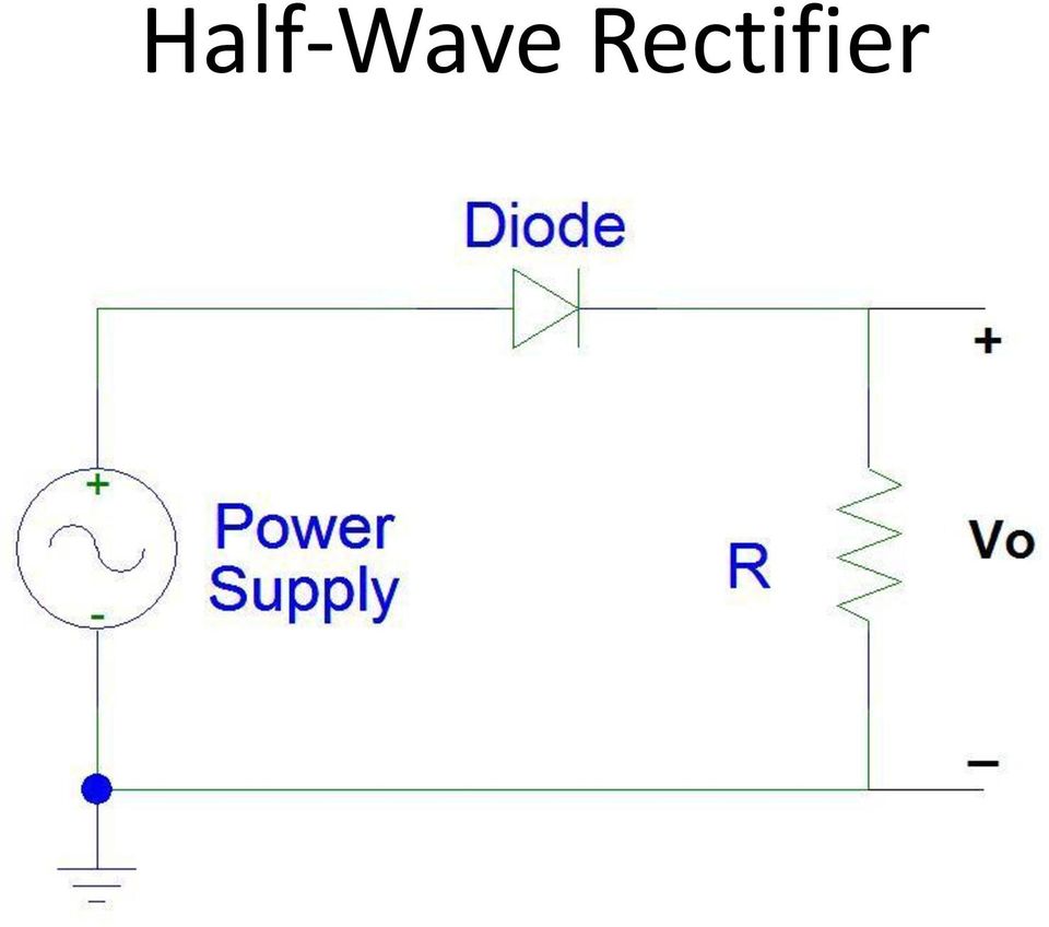
8 Approach to Solution Assume that the frequency of the AC power supply is low in comparison to the frequency response of the diode circuit I.e., the parasitic capacitance and inductance of the diode and the resistor do not affect the magnitude or phase of the output voltage This allows us to use the DC models for the diode to replace the AC power supply with a variable DC power supply To calculate the output voltage for specific set of input voltages and interpolate the value of output voltage in between.

9
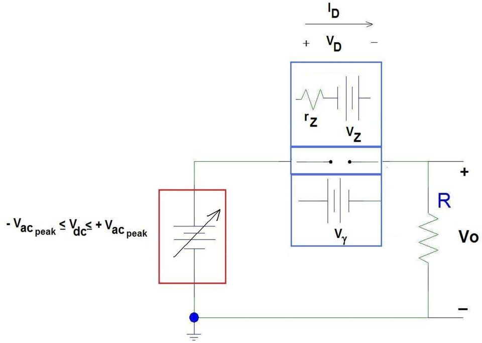
10 What do you need to know? AC power supply Minimum and maximum voltages Diode Turn-on voltage, g Breakdown voltage, BR or the Zener voltage at a particular reverse bias current and Zener resistance, Z and R Z

11 Solution Three to four calculations 1. When the diode is at its maximum forward bias condition 2. When the diode voltage is equal to its turn-on voltage, but the diode current is zero 3. When the diode is at its maximum reverse bias condition 4. When the diode is just entering breakdown NOTE: This is not a desired condition for the half-wave rectifier, but may accidently occur if an incorrect diode is selected for the AC power supply connected to the circuit.

12 Example

13 Decisions on Diode Models Since the maximum voltage is +10, there is probably is enough voltage available to turn the diode on. So, the ON model for the diode will likely be used. Since the minimum voltage is -10 which is much less than - Z, we do not need to use the BREAKDOWN model. As the voltage of the AC power supply can be negative, it is likely that the OFF model for the diode will be used.

14 Calculation 1: The magnitude of the AC voltage is at its maximum

15

16 I I D o 46.5mA 200 I D 9.3 D 0

17 Calculation 2: The magnitude of the AC voltage just turns on the diode

18 I D dc o dc I 0mA I D 0 D 0

19 Calculation 3: The magnitude of the AC voltage is at its minimum

20 10 I D D o D 0mA I 200 I D 0 D 0

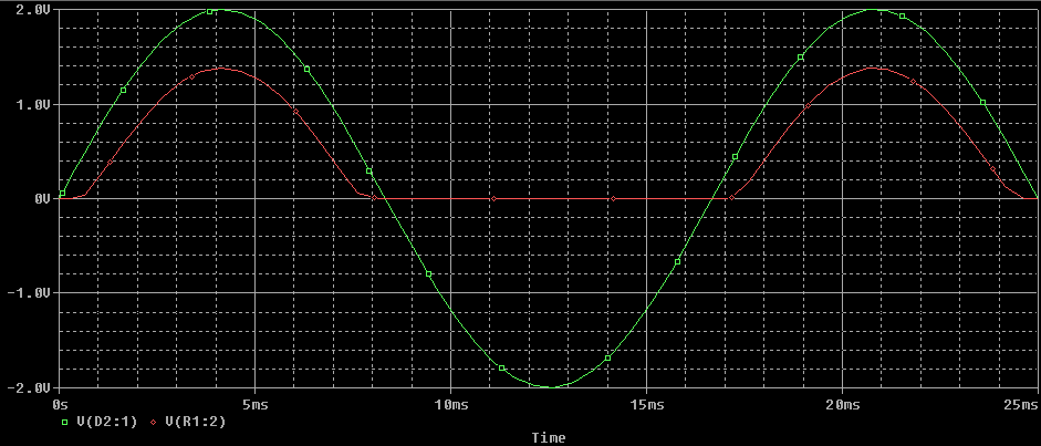
21 Output oltage as a Function of Time Since the input voltage was actually an AC power supply, the output voltage must vary with time. The maximum output voltage is 9.3. The output voltage is 0 when the input voltage is 0.7. The minimum output voltage is 0.
22 o vs. Time
23 oltage Transfer Characteristic g
24 If one used the Ideal Diode equation to determine o There will be a nonlinear dependence between the power supply voltage and the output voltage because of the nonlinear dependence of ID with D when the diode is forward biased. There will be a voltage drop when the diode is reverse biased because of the reverse saturation current. I D q D I e nkt 1 o
25 PSpice Simple diode model uses the Ideal Diode equation. The models based on real diode parts are more complex, incorporating parasitic resistances, capacitances, and temperature dependences Hence, your hand calculations are not going to match the answers obtained when simulating the circuit using Pspice. However, they should be roughly the same.
26
27 oltage Transfer Characteristic

28 Frequency Response Though the output voltage is plotted incorrectly in Pspice, there is a maximum frequency of operation at which the diode no longer operates via any of the models we have discussed thus far.

29 Output voltage when input power supply is operating at 1GHz
30 Criteria for Diode Selection For maximum power to the load while the diode is conducting, the diode should have a small turn-on voltage. For the minimum power loss while the diode is off, the reverse saturation current should be low. 2 2 Dn n D i p ni I o qa Ln Na Lp Nd bi kt N N ln d q n 2 i a
31 Last Criteria The breakdown voltage must be greater than the magnitude of the larger reverse bias applied to the diode. BR is inversely proportional to the doping level of the most lightly doped side of the p-n junction The maximum reverse bias voltage is called the peak inverse voltage (PI).
32 Alternative Circuit: Half-Wave Rectifier
33 Smoothing the output voltage
34 Example Transformer steps down the input voltage to +/- 12 Diode used is a D1N4002 1k resistor 10mF capacitor

35 M P r L T - P T p
36 Wait that statement about the diode selection criteria needs to be modified for this circuit! Let s assume that the capacitor doesn t have a chance to discharge before the voltage of the input power supply is at its minimum value. The diode is reverse biased at twice the magnitude of the peak input voltage So, the criteria on the breakdown voltage is even more severe Now, assume that the reverse saturation current is large. This current will help speed the discharge rate of the capacitor, causing the ripple voltage to be larger than expected. So, the criteria on the reverse breakdown voltage is still important. However, it can be ignored if the reverse saturation current is less than 10% of the minimum current through the load resistor while the capacitor is discharging.
 as it discharges through the resistor (1k) Until the input voltage equals the output voltage plus the turn-on voltage of the diode When the diode turns on and the capacitor begins to be")
37 Ripple oltage If you assume that the diode turns off (becomes an open) as soon as the input voltage begins to drop from its maximum value Then the output voltage is the voltage across the capacitor (10mF) as it discharges through the resistor (1k) Until the input voltage equals the output voltage plus the turn-on voltage of the diode When the diode turns on and the capacitor begins to be recharged.
38 Ripple oltage frc f T RC T T T RC T e M r p p M r p M r RC T M L M r 1 then, if ) (1 ' ' '
39 Power Conversion Efficiency the capacitor can assumed to be linearly decreasing. drop across the voltage T and assume that T' you if - wave rectifier filtered half for a ) ( - wave rectifier half for a P r M P L M P M
40 Things to Know From This Lecture Optimal diode is a lightly doped p-n junction For a properly designed circuit, ON and OFF piecewise models are used Reverse saturation current of a lightly doped p-n junction is not ideal for this application Three calculations are needed to map the output voltage using piecewise model Max. input voltage, minimum input voltage, and input voltage at which the diode model switches between ON and OFF Output voltage when diode is on varies linearly with input voltage: o = in g A transformer is used to step down (or up) the input voltage as needed for the application.
41 Results using Ideal Diode Equation Current does flow whenever in is not equal to zero o does not vary linearly with in Pspice Simulation Uses a more complex model based on the Ideal Diode Equation Inclusion of parasitic capacitances means there is a frequency dependence to the circuit operation Not shown was the temperature dependence of the operation (but you can do this at home). Not all of the answers obtained from the simulation are correct. First cycle in transient response is different because initial charge on capacitors (external and parasitic) was zero.
42 Filtered half-wave rectifier results in a better dc output voltage Ripple voltage is a function of the maximum voltage on the capacitor, the frequency of the input voltage, and the RC time constant of the load. Better power conversion than simple half-wave rectifier circuit Significantly increases the maximum reverse bias voltage on the diode Reverse saturation current of the diode may influence ripple voltage
The full wave rectifier consists of two diodes and a resister as shown in Figure
 The Full-Wave Rectifier The full wave rectifier consists of two diodes and a resister as shown in Figure The transformer has a centre-tapped secondary winding. This secondary winding has a lead attached
Properties of electrical signals
 DC Voltage Component (Average voltage) Properties of electrical signals v(t) = V DC + v ac (t) V DC is the voltage value displayed on a DC voltmeter Triangular waveform DC component Half-wave rectifier
Rectifier circuits & DC power supplies
 Rectifier circuits & DC power supplies Goal: Generate the DC voltages needed for most electronics starting with the AC power that comes through the power line? 120 V RMS f = 60 Hz T = 1667 ms) = )sin How
Lecture - 4 Diode Rectifier Circuits
 Basic Electronics (Module 1 Semiconductor Diodes) Dr. Chitralekha Mahanta Department of Electronics and Communication Engineering Indian Institute of Technology, Guwahati Lecture - 4 Diode Rectifier Circuits
See Horenstein 4.3 and 4.4
 EE 462: Laboratory # 4 DC Power Supply Circuits Using Diodes by Drs. A.V. Radun and K.D. Donohue (2/14/07) Department of Electrical and Computer Engineering University of Kentucky Lexington, KY 40506 Updated
Chapter 3. Diodes and Applications. Introduction [5], [6]
![Chapter 3. Diodes and Applications. Introduction [5], [6]](/thumbs/40/21801962.jpg "Chapter 3. Diodes and Applications. Introduction [5], [6]") Chapter 3 Diodes and Applications Introduction [5], [6] Diode is the most basic of semiconductor device. It should be noted that the term of diode refers to the basic p-n junction diode. All other diode
Chapter 3 Diodes and Applications Introduction [5], [6] Diode is the most basic of semiconductor device. It should be noted that the term of diode refers to the basic p-n junction diode. All other diode
electronics fundamentals
 electronics fundamentals circuits, devices, and applications THOMAS L. FLOYD DAVID M. BUCHLA Lesson 1: Diodes and Applications Center-Tapped Full-wave Rectifier The center-tapped (CT) full-wave rectifier
Fundamentals of Microelectronics
 Fundamentals of Microelectronics CH1 Why Microelectronics? CH2 Basic Physics of Semiconductors CH3 Diode Circuits CH4 Physics of Bipolar Transistors CH5 Bipolar Amplifiers CH6 Physics of MOS Transistors
Diode Circuits. Operating in the Reverse Breakdown region. (Zener Diode)
") Diode Circuits Operating in the Reverse Breakdown region. (Zener Diode) In may applications, operation in the reverse breakdown region is highly desirable. The reverse breakdown voltage is relatively insensitive
Diode Circuits Operating in the Reverse Breakdown region. (Zener Diode) In may applications, operation in the reverse breakdown region is highly desirable. The reverse breakdown voltage is relatively insensitive
ANADOLU UNIVERSITY DEPARTMENT OF ELECTRICAL AND ELECTRONICS ENGINEERING
 ANADOLU UNIVERSITY DEPARTMENT OF ELECTRICAL AND ELECTRONICS ENGINEERING EEM 102 INTRODUCTION TO ELECTRICAL ENGINEERING EXPERIMENT 9: DIODES AND DC POWER SUPPLY OBJECTIVE: To observe how a diode functions
DIODE CIRCUITS LABORATORY. Fig. 8.1a Fig 8.1b
 DIODE CIRCUITS LABORATORY A solid state diode consists of a junction of either dissimilar semiconductors (pn junction diode) or a metal and a semiconductor (Schottky barrier diode). Regardless of the type,
The D.C Power Supply
 The D.C Power Supply Voltage Step Down Electrical Isolation Converts Bipolar signal to Unipolar Half or Full wave Smoothes the voltage variation Still has some ripples Reduce ripples Stabilize the output
3. Diodes and Diode Circuits. 3. Diodes and Diode Circuits TLT-8016 Basic Analog Circuits 2005/2006 1
 3. Diodes and Diode Circuits 3. Diodes and Diode Circuits TLT-8016 Basic Analog Circuits 2005/2006 1 3.1 Diode Characteristics Small-Signal Diodes Diode: a semiconductor device, which conduct the current
Diode Applications. As we have already seen the diode can act as a switch Forward biased or reverse biased - On or Off.
 Diode Applications Diode Switching As we have already seen the diode can act as a switch Forward biased or reverse biased - On or Off. Voltage Rectifier A voltage rectifier is a circuit that converts an
CHAPTER 2B: DIODE AND APPLICATIONS. D.Wilcher
 CHAPTER 2B: DIODE AND APPLICATIONS D.Wilcher 1 CHAPTER 2B: OBJECTIVES Analyze the operation of 3 basic types of rectifiers Describe the operation of rectifier filters and IC regulators Analyze the operation
Lab Report No.1 // Diodes: A Regulated DC Power Supply Omar X. Avelar Omar de la Mora Diego I. Romero
 Instituto Tecnológico y de Estudios Superiores de Occidente (ITESO) Periférico Sur Manuel Gómez Morín 8585, Tlaquepaque, Jalisco, México, C.P. 45090 Analog Electronic Devices (ESI038 / SE047) Dr. Esteban
Precision Diode Rectifiers
 by Kenneth A. Kuhn March 21, 2013 Precision half-wave rectifiers An operational amplifier can be used to linearize a non-linear function such as the transfer function of a semiconductor diode. The classic
Homework Assignment 03
 Question 1 (2 points each unless noted otherwise) Homework Assignment 03 1. A 9-V dc power supply generates 10 W in a resistor. What peak-to-peak amplitude should an ac source have to generate the same
Diode Applications. by Kenneth A. Kuhn Sept. 1, 2008. This note illustrates some common applications of diodes.
 by Kenneth A. Kuhn Sept. 1, 2008 This note illustrates some common applications of diodes. Power supply applications A common application for diodes is converting AC to DC. Although half-wave rectification
Analog & Digital Electronics Course No: PH-218
 Analog & Digital Electronics Course No: PH-18 Lec 3: Rectifier and Clipper circuits Course nstructors: Dr. A. P. VAJPEY Department of Physics, ndian nstitute of Technology Guwahati, ndia 1 Rectifier Circuits:
Yrd. Doç. Dr. Aytaç Gören
 H2 - AC to DC Yrd. Doç. Dr. Aytaç Gören ELK 2018 - Contents W01 Basic Concepts in Electronics W02 AC to DC Conversion W03 Analysis of DC Circuits W04 Transistors and Applications (H-Bridge) W05 Op Amps
LABORATORY 10 TIME AVERAGES, RMS VALUES AND THE BRIDGE RECTIFIER. Bridge Rectifier
 LABORATORY 10 TIME AVERAGES, RMS VALUES AND THE BRIDGE RECTIFIER Full-wave Rectification: Bridge Rectifier For many electronic circuits, DC supply voltages are required but only AC voltages are available.
Introduction to Power Supplies
 Introduction to Power Supplies INTRODUCTION Virtually every piece of electronic equipment e g computers and their peripherals calculators TV and hi-fi equipment and instruments is powered from a DC power
Chapter 2 MENJANA MINDA KREATIF DAN INOVATIF
 Chapter 2 DIODE part 2 MENJANA MINDA KREATIF DAN INOATIF objectives Diode with DC supply circuit analysis serial & parallel Diode d applications the DC power supply & Clipper Analysis & Design of rectifier
Supplement Reading on Diode Circuits. http://www.inst.eecs.berkeley.edu/ edu/~ee40/fa09/handouts/ee40_mos_circuit.pdf
 EE40 Lec 18 Diode Circuits Reading: Chap. 10 of Hambley Supplement Reading on Diode Circuits http://www.inst.eecs.berkeley.edu/ edu/~ee40/fa09/handouts/ee40_mos_circuit.pdf Slide 1 Diodes Circuits Load
Analog Electronics I. Laboratory
 Analog Electronics I Laboratory Exercise 1 DC Power Supply Circuits Aim of the exercise The aim of this laboratory exercise is to become familiar with rectifying circuits and voltage stabilization techniques
ENGR-4300 Electronic Instrumentation Quiz 4 Spring 2011 Name Section
 ENGR-4300 Electronic Instrumentation Quiz 4 Spring 2011 Name Section Question I (20 points) Question II (20 points) Question III (20 points) Question IV (20 points) Question V (20 points) Total (100 points)
Figure 1. Diode circuit model
 Semiconductor Devices Non-linear Devices Diodes Introduction. The diode is two terminal non linear device whose I-V characteristic besides exhibiting non-linear behavior is also polarity dependent. The
LAB IV. SILICON DIODE CHARACTERISTICS
 LAB IV. SILICON DIODE CHARACTERISTICS 1. OBJECTIVE In this lab you are to measure I-V characteristics of rectifier and Zener diodes in both forward and reverse-bias mode, as well as learn to recognize
Chapter 22 Further Electronics
 hapter 22 Further Electronics washing machine has a delay on the door opening after a cycle of washing. Part of this circuit is shown below. s the cycle ends, switch S closes. t this stage the capacitor
Semiconductor Diode. It has already been discussed in the previous chapter that a pn junction conducts current easily. Principles of Electronics
 76 6 Principles of Electronics Semiconductor Diode 6.1 Semiconductor Diode 6.3 Resistance of Crystal Diode 6.5 Crystal Diode Equivalent Circuits 6.7 Crystal Diode Rectifiers 6.9 Output Frequency of Half-Wave
Unit/Standard Number. High School Graduation Years 2010, 2011 and 2012
 1 Secondary Task List 100 SAFETY 101 Demonstrate an understanding of State and School safety regulations. 102 Practice safety techniques for electronics work. 103 Demonstrate an understanding of proper
Diodes and Transistors
 Diodes What do we use diodes for? Diodes and Transistors protect circuits by limiting the voltage (clipping and clamping) turn AC into DC (voltage rectifier) voltage multipliers (e.g. double input voltage)
Power supplies. EE328 Power Electronics Assoc. Prof. Dr. Mutlu BOZTEPE Ege University, Dept. of E&E
 Power supplies EE328 Power Electronics Assoc. Prof. Dr. Mutlu BOZTEPE Ege University, Dept. of E&E EE328 POWER ELECTRONICS Outline of lecture Introduction to power supplies Modelling a power transformer
Power Supplies. 1.0 Power Supply Basics. www.learnabout-electronics.org. Module
 Module 1 www.learnabout-electronics.org Power Supplies 1.0 Power Supply Basics What you ll learn in Module 1 Section 1.0 Power Supply Basics. Basic functions of a power supply. Safety aspects of working
Chapter 3 Diode Circuits. 3.1 Ideal Diode 3.2 PN Junction as a Diode 3.3 Applications of Diodes
 Chapter 3 Diode Circuits 3.1 deal Diode 3.2 PN Junction as a Diode 3.3 Applications of Diodes 1 Diode s Application: Cell Phone Charger An important application of diode is chargers. 充 電 器 Diode acts as
= V peak 2 = 0.707V peak
 BASIC ELECTRONICS - RECTIFICATION AND FILTERING PURPOSE Suppose that you wanted to build a simple DC electronic power supply, which operated off of an AC input (e.g., something you might plug into a standard
Diodes. 1 Introduction 1 1.1 Diode equation... 2 1.1.1 Reverse Bias... 2 1.1.2 Forward Bias... 2 1.2 General Diode Specifications...
 Diodes Contents 1 Introduction 1 1.1 Diode equation................................... 2 1.1.1 Reverse Bias................................ 2 1.1.2 Forward Bias................................ 2 1.2 General
EE 255 ELECTRONICS I LABORATORY EXPERIMENT 2 POWER SUPPLY DESIGN CONSIDERATIONS
 EE 55 ELETRONIS I LABORATORY EXPERIMENT POWER SUPPLY ESIGN ONSIERATIONS OBJETIES In this experiment you will Learn how to select the best rectifier circuit for your application Gain experience in designing
LEP 4.4.07. Rectifier circuits
 Related topics Half-wave rectifier, full-wave rectifier, Graetz rectifier, diode, Zener diode, avalanche effect, charging capacitor, ripple, r.m.s. value, internal resistance, smoothing factor, ripple
Transistor Models. ampel
 Transistor Models Review of Transistor Fundamentals Simple Current Amplifier Model Transistor Switch Example Common Emitter Amplifier Example Transistor as a Transductance Device - Ebers-Moll Model Other
Lab 1 Diode Characteristics
 Lab 1 Diode Characteristics Purpose The purpose of this lab is to study the characteristics of the diode. Some of the characteristics that will be investigated are the I-V curve and the rectification properties.
Lab 3 Rectifier Circuits
 ECET 242 Electronic Circuits Lab 3 Rectifier Circuits Page 1 of 5 Name: Objective: Students successfully completing this lab exercise will accomplish the following objectives: 1. Learn how to construct
Experiment 2 Diode Applications: Rectifiers
 ECE 3550 - Practicum Fall 2007 Experiment 2 Diode Applications: Rectifiers Objectives 1. To investigate the characteristics of half-wave and full-wave rectifier circuits. 2. To recognize the usefulness
The Electronic Power Supply. 1. Problem Statement ( 4 situations) 2. Sample Solution 3. Notes for the Instructor
 2. Sample Solution 3. Notes for the Instructor") I N T E R D I S C I P L I N A R Y L I V E L Y A P P L I C A T I O N S P R O J E C T M A T E R I A L S 1. Problem Statement ( 4 situations) 2. Sample Solution 3. Notes for the Instructor Computing Requirements:
I N T E R D I S C I P L I N A R Y L I V E L Y A P P L I C A T I O N S P R O J E C T M A T E R I A L S 1. Problem Statement ( 4 situations) 2. Sample Solution 3. Notes for the Instructor Computing Requirements:
AC Direct Off-Line Power Supplies
 AC Direct Off-Line Power Supplies r Introduction Many DC power supplies found in electronic systems, including those in this Tech School, rectify the 120 volts available at an electric outlet. The initial
GenTech Practice Questions
 GenTech Practice Questions Basic Electronics Test: This test will assess your knowledge of and ability to apply the principles of Basic Electronics. This test is comprised of 90 questions in the following
ENEE 313, Spr 09 Midterm II Solution
 ENEE 313, Spr 09 Midterm II Solution PART I DRIFT AND DIFFUSION, 30 pts 1. We have a silicon sample with non-uniform doping. The sample is 200 µm long: In the figure, L = 200 µm= 0.02 cm. At the x = 0
BJT Characteristics and Amplifiers
 BJT Characteristics and Amplifiers Matthew Beckler beck0778@umn.edu EE2002 Lab Section 003 April 2, 2006 Abstract As a basic component in amplifier design, the properties of the Bipolar Junction Transistor
Silicon Controlled Rectifiers
 554 20 Principles of Electronics Silicon Controlled Rectifiers 20.1 Silicon Controlled Rectifier (SCR) 20.2 Working of SCR 20.3 Equivalent Circuit of SCR 20.4 Important Terms 20.5 V-I Characteristics of
AN3022. Establishing the Minimum Reverse Bias for a PIN Diode in a High-Power Switch. 1. Introduction. Rev. V2
 Abstract - An important circuit design parameter in a high-power p-i-n diode application is the selection of an appropriate applied dc reverse bias voltage. Until now, this important circuit parameter
= (0.400 A) (4.80 V) = 1.92 W = (0.400 A) (7.20 V) = 2.88 W
 (4.80 V) = 1.92 W = (0.400 A) (7.20 V) = 2.88 W") Physics 2220 Module 06 Homework 0. What are the magnitude and direction of the current in the 8 Ω resister in the figure? Assume the current is moving clockwise. Then use Kirchhoff's second rule: 3.00
Physics 2220 Module 06 Homework 0. What are the magnitude and direction of the current in the 8 Ω resister in the figure? Assume the current is moving clockwise. Then use Kirchhoff's second rule: 3.00
Pulse Width Modulation (PWM) LED Dimmer Circuit. Using a 555 Timer Chip
 LED Dimmer Circuit. Using a 555 Timer Chip") Pulse Width Modulation (PWM) LED Dimmer Circuit Using a 555 Timer Chip Goals of Experiment Demonstrate the operation of a simple PWM circuit that can be used to adjust the intensity of a green LED by varying
Pulse Width Modulation (PWM) LED Dimmer Circuit Using a 555 Timer Chip Goals of Experiment Demonstrate the operation of a simple PWM circuit that can be used to adjust the intensity of a green LED by varying
Line Reactors and AC Drives
 Line Reactors and AC Drives Rockwell Automation Mequon Wisconsin Quite often, line and load reactors are installed on AC drives without a solid understanding of why or what the positive and negative consequences
David L. Senasack June, 2006 Dale Jackson Career Center, Lewisville Texas. The PN Junction
 David L. Senasack June, 2006 Dale Jackson Career Center, Lewisville Texas The PN Junction Objectives: Upon the completion of this unit, the student will be able to; name the two categories of integrated
Zero voltage drop synthetic rectifier
 Zero voltage drop synthetic rectifier Vratislav Michal Brno University of Technology, Dpt of Theoretical and Experimental Electrical Engineering Kolejní 4/2904, 612 00 Brno Czech Republic vratislav.michal@gmail.com,
0.9V Boost Driver PR4403 for White LEDs in Solar Lamps
 0.9 Boost Driver for White LEDs in Solar Lamps The is a single cell step-up converter for white LEDs operating from a single rechargeable cell of 1.2 supply voltage down to less than 0.9. An adjustable
SECTION 13. Multipliers. Outline of Multiplier Design Process:
 SECTION 13 Multipliers VMI manufactures many high voltage multipliers, most of which are custom designed for specific requirements. The following information provides general information and basic guidance
DEGREE: Bachelor in Biomedical Engineering YEAR: 2 TERM: 2 WEEKLY PLANNING
 SESSION WEEK COURSE: Electronic Technology in Biomedicine DEGREE: Bachelor in Biomedical Engineering YEAR: 2 TERM: 2 WEEKLY PLANNING DESCRIPTION GROUPS (mark X) SPECIAL ROOM FOR SESSION (Computer class
Section 3. Sensor to ADC Design Example
 Section 3 Sensor to ADC Design Example 3-1 This section describes the design of a sensor to ADC system. The sensor measures temperature, and the measurement is interfaced into an ADC selected by the systems
Basic Electronics Prof. Dr. Chitralekha Mahanta Department of Electronics and Communication Engineering Indian Institute of Technology, Guwahati
 Basic Electronics Prof. Dr. Chitralekha Mahanta Department of Electronics and Communication Engineering Indian Institute of Technology, Guwahati Module: 2 Bipolar Junction Transistors Lecture-2 Transistor
13. Diode Rectifiers, Filters, and Power Supplies
 1 13. Diode Rectifiers, Filters, and Power Supplies Introduction A power supply takes Alternating Current or A.C. power from your electric utility (Con Edison) and converts the A.C. electrical current
Current Ripple Factor of a Buck Converter
 Application Note Edwin Wang AN1 April 14 Current Ripple Factor of a Buck Converter Abstract Inductor and capacitor forms a low-pass filter in a buck converter. The corner frequency the C filter is always
BJT Ebers-Moll Model and SPICE MOSFET model
 Department of Electrical and Electronic Engineering mperial College London EE 2.3: Semiconductor Modelling in SPCE Course homepage: http://www.imperial.ac.uk/people/paul.mitcheson/teaching BJT Ebers-Moll
Modeling and Analysis of DC Link Bus Capacitor and Inductor Heating Effect on AC Drives (Part I)
") 00-00-//$0.00 (c) IEEE IEEE Industry Application Society Annual Meeting New Orleans, Louisiana, October -, Modeling and Analysis of DC Link Bus Capacitor and Inductor Heating Effect on AC Drives (Part
00-00-//$0.00 (c) IEEE IEEE Industry Application Society Annual Meeting New Orleans, Louisiana, October -, Modeling and Analysis of DC Link Bus Capacitor and Inductor Heating Effect on AC Drives (Part
Circuits with inductors and alternating currents. Chapter 20 #45, 46, 47, 49
 Circuits with inductors and alternating currents Chapter 20 #45, 46, 47, 49 RL circuits Ch. 20 (last section) Symbol for inductor looks like a spring. An inductor is a circuit element that has a large
Common-Emitter Amplifier
 Common-Emitter Amplifier A. Before We Start As the title of this lab says, this lab is about designing a Common-Emitter Amplifier, and this in this stage of the lab course is premature, in my opinion,
7-41 POWER FACTOR CORRECTION
 POWER FTOR CORRECTION INTRODUCTION Modern electronic equipment can create noise that will cause problems with other equipment on the same supply system. To reduce system disturbances it is therefore essential
CMOS Power Consumption and C pd Calculation
 CMOS Power Consumption and C pd Calculation SCAA035B June 1997 1 IMPORTANT NOTICE Texas Instruments (TI) reserves the right to make changes to its products or to discontinue any semiconductor product or
Chapter 20 Quasi-Resonant Converters
 Chapter 0 Quasi-Resonant Converters Introduction 0.1 The zero-current-switching quasi-resonant switch cell 0.1.1 Waveforms of the half-wave ZCS quasi-resonant switch cell 0.1. The average terminal waveforms
Regulated D.C. Power Supply
 442 17 Principles of Electronics Regulated D.C. Power Supply 17.1 Ordinary D.C. Power Supply 17.2 Important Terms 17.3 Regulated Power Supply 17.4 Types of Voltage Regulators 17.5 Zener Diode Voltage Regulator
FPAB20BH60B PFC SPM 3 Series for Single-Phase Boost PFC
 FPAB20BH60B PFC SPM 3 Series for Single-Phase Boost PFC Features UL Certified No. E209204 (UL1557) 600 V - 20 A Single-Phase Boost PFC with Integral Gate Driver and Protection Very Low Thermal Resistance
Lecture 24. Inductance and Switching Power Supplies (how your solar charger voltage converter works)
") Lecture 24 Inductance and Switching Power Supplies (how your solar charger voltage converter works) Copyright 2014 by Mark Horowitz 1 Roadmap: How Does This Work? 2 Processor Board 3 More Detailed Roadmap
Lecture 24 Inductance and Switching Power Supplies (how your solar charger voltage converter works) Copyright 2014 by Mark Horowitz 1 Roadmap: How Does This Work? 2 Processor Board 3 More Detailed Roadmap
Diodes have an arrow showing the direction of the flow.
 The Big Idea Modern circuitry depends on much more than just resistors and capacitors. The circuits in your computer, cell phone, Ipod depend on circuit elements called diodes, inductors, transistors,
Power Electronics. Prof. K. Gopakumar. Centre for Electronics Design and Technology. Indian Institute of Science, Bangalore.
 Power Electronics Prof. K. Gopakumar Centre for Electronics Design and Technology Indian Institute of Science, Bangalore Lecture - 1 Electric Drive Today, we will start with the topic on industrial drive
CONSTRUCTING A VARIABLE POWER SUPPLY UNIT
 CONSTRUCTING A VARIABLE POWER SUPPLY UNIT Building a power supply is a good way to put into practice many of the ideas we have been studying about electrical power so far. Most often, power supplies are
EXPERIMENT 1 SINGLE-PHASE FULL-WAVE RECTIFIER AND LINEAR REGULATOR
 YEDITEPE UNIERSITY ENGINEERING & RCHITECTURE FCULTY INDUSTRIL ELECTRONICS LBORTORY EE 432 INDUSTRIL ELECTRONICS EXPERIMENT 1 SINGLEPHSE FULLWE RECTIFIER ND LINER REGULTOR Introduction: In this experiment
POWER SUPPLY MODEL XP-15. Instruction Manual ELENCO
 POWER SUPPLY MODEL XP-15 Instruction Manual ELENCO Copyright 2013 by Elenco Electronics, Inc. REV-A 753020 All rights reserved. No part of this book shall be reproduced by any means; electronic, photocopying,
The 2N3393 Bipolar Junction Transistor
 The 2N3393 Bipolar Junction Transistor Common-Emitter Amplifier Aaron Prust Abstract The bipolar junction transistor (BJT) is a non-linear electronic device which can be used for amplification and switching.
FREQUENCY CONTROLLED AC MOTOR DRIVE
 FREQUENCY CONTROLLED AC MOTOR DRIVE 1.0 Features of Standard AC Motors The squirrel cage induction motor is the electrical motor motor type most widely used in industry. This leading position results mainly
X-ray Imaging System. X-Ray Circuit. Principles of Imaging Science II (RAD 120) X-ray Imaging System Circuitry
 X-ray Imaging System Circuitry") Principles of Imaging Science II (RAD 120) X-ray Imaging System Circuitry X-ray Imaging System Operating console Set x-ray tube current (quantity) and voltage (quality) Controls line compensation, kvp,
Principles of Imaging Science II (RAD 120) X-ray Imaging System Circuitry X-ray Imaging System Operating console Set x-ray tube current (quantity) and voltage (quality) Controls line compensation, kvp,
LM2704 Micropower Step-up DC/DC Converter with 550mA Peak Current Limit
 Micropower Step-up DC/DC Converter with 550mA Peak Current Limit General Description The LM2704 is a micropower step-up DC/DC in a small 5-lead SOT-23 package. A current limited, fixed off-time control
LM 358 Op Amp. If you have small signals and need a more useful reading we could amplify it using the op amp, this is commonly used in sensors.
 LM 358 Op Amp S k i l l L e v e l : I n t e r m e d i a t e OVERVIEW The LM 358 is a duel single supply operational amplifier. As it is a single supply it eliminates the need for a duel power supply, thus
Episode 126: Capacitance and the equation C =Q/V
 Episode 126: Capacitance and the equation C =Q/V Having established that there is charge on each capacitor plate, the next stage is to establish the relationship between charge and potential difference
III. Reaction Kinetics
 III. Reaction Kinetics Lecture 13: Butler-Volmer equation Notes by ChangHoon Lim (and MZB) 1. Interfacial Equilibrium At lecture 11, the reaction rate R for the general Faradaic half-cell reaction was
MIC2940A/2941A. Features. General Description. Applications. Pin Configuration. 1.2A Low-Dropout Voltage Regulator
 MIC294A/2941A 1.2A Low-Dropout oltage Regulator General Description The MIC294A and MIC2941A are bulletproof efficient voltage regulators with very low dropout voltage (typically 4 at light loads and 35
Current and Temperature Ratings
 Document 361-1 Current and Temperature Ratings Introduction This application note describes: How to interpret Coilcraft inductor current and temperature ratings Our current ratings measurement method and
OBJECTIVE QUESTIONS IN ANALOG ELECTRONICS
 1. The early effect in a bipolar junction transistor is caused by (a) fast turn-on (c) large collector-base reverse bias (b)fast turn-off (d) large emitter-base forward bias 2. MOSFET can be used as a
Lecture 3: DC Analysis of Diode Circuits.
 Whites, EE 320 Lecture 3 Page 1 of 10 Lecture 3: DC Analysis of Diode Circuits. We ll now move on to the DC analysis of diode circuits. Applications will be covered in following lectures. Let s consider
Output Ripple and Noise Measurement Methods for Ericsson Power Modules
 Output Ripple and Noise Measurement Methods for Ericsson Power Modules Design Note 022 Ericsson Power Modules Ripple and Noise Abstract There is no industry-wide standard for measuring output ripple and
Type SA-1 Generator Differential Relay
 ABB Automation Inc. Substation Automation and Protection Division Coral Springs, FL 33065 Instruction Leaflet 41-348.11C Effective: November 1999 Supersedes I.L. 41-348.11B, Dated August 1986 ( ) Denotes
Efficient and reliable operation of LED lighting is dependent on the right choice of current-limiting resistor
 Efficient and reliable operation of LED lighting is dependent on the right choice of current-limiting resistor Phil Ebbert, VP of Engineering, Riedon Inc. Introduction Not all resistors are the same and
LM101A LM201A LM301A Operational Amplifiers
 LM101A LM201A LM301A Operational Amplifiers General Description The LM101A series are general purpose operational amplifiers which feature improved performance over industry standards like the LM709 Advanced
Design A High Performance Buck or Boost Converter With Si9165
 Design A High Performance Buck or Boost Converter With Si9165 AN723 AN723 by Kin Shum INTRODUCTION The Si9165 is a controller IC designed for dc-to-dc conversion applications with 2.7- to 6- input voltage.
BASIC ELECTRICAL AND ELECTRONICS ENGINEERING
 Questions and Answers for Units III, IV & V I B.Tech I Sem BASIC ELECTRICAL AND ELECTRONICS ENGINEERING N. Madhusudhana Rao Department of ECE GRIET Syllabus UNIT I: ELECTRICAL and SINGLE PHASE AC CIRCUITS
AC/DC Power Supply Reference Design. Advanced SMPS Applications using the dspic DSC SMPS Family
 AC/DC Power Supply Reference Design Advanced SMPS Applications using the dspic DSC SMPS Family dspic30f SMPS Family Excellent for Digital Power Conversion Internal hi-res PWM Internal high speed ADC Internal
Designers Series XII. Switching Power Magazine. Copyright 2005
 Designers Series XII n this issue, and previous issues of SPM, we cover the latest technologies in exotic high-density power. Most power supplies in the commercial world, however, are built with the bread-and-butter
Transistor Amplifiers
 Physics 3330 Experiment #7 Fall 1999 Transistor Amplifiers Purpose The aim of this experiment is to develop a bipolar transistor amplifier with a voltage gain of minus 25. The amplifier must accept input
AN105. Introduction: The Nature of VCRs. Resistance Properties of FETs
 Introduction: The Nature of s A voltage-controlled resistor () may be defined as a three-terminal variable resistor where the resistance value between two of the terminals is controlled by a voltage potential
Analog Optical Isolators VACTROLS
 Analog Optical Isolators VACTROLS What Are Analog Optical Isolators? PerkinElmer Optoelectronics has been a leading manufacturer of analog optical isolators for over twenty years and makes a broad range