TEPZZ ZZ _5ZA_T EP A1 (19) (11) EP A1 (12) EUROPEAN PATENT APPLICATION. (51) Int Cl.: B60L 15/20 ( ) B60W 30/18 (2012.
|
|
|
- Cameron Booker
- 7 years ago
- Views:
Transcription
1 (19) TEPZZ ZZ _ZA_T (11) EP A1 (12) EUROPEAN PATENT APPLICATION (43) Date of publication: Bulletin 2016/14 (1) Int Cl.: B60L /20 ( ) B60W 30/18 ( ) (21) Application number: (22) Date of filing: (84) Designated Contracting States: AL AT BE BG CH CY CZ DE DK EE ES FI FR GB GR HR HU IE IS IT LI LT LU LV MC MK MT NL NO PL PT RO RS SE SI SK SM TR Designated Extension States: BA ME Designated Validation States: MA (30) Priority: KR (71) Applicants: Hyundai Motor Company Seoul (KR) Kia Motors Corporation Seoul (KR) (72) Inventors: Huh, Jee Wook Gyeonggi-do (KR) Du, Gwang Il Incheon (KR) Kim, Sung Deok Gyeonggi-do (KR) Cho, Teh Hwan Gyeonggi-do (KR) (74) Representative: Viering, Jentschura & Partner mbb Patent- und Rechtsanwälte Grillparzerstrasse München (DE) (4) APPARATUS AND METHOD FOR CONTROLLING CREEP TORQUE OF HYBRID ELECTRIC VEHICLE (7) An apparatus and a method for controlling a creep torque of a hybrid electric vehicle that outputs the creep torque to improve shift feel and fuel consumption of the hybrid electric vehicle, may include the method for controlling a creep torque of a hybrid electric vehicle that may include detecting data of the hybrid electric vehicle for controlling the creep torque, determining whether a vehicle speed is greater than or equal to a predetermined speed and the hybrid electric vehicle is shifting from a current shift stage to 1 stage when the current shift stage is 3 stage or 2 stage, applying a creep torque factor depending on a shift stage and a brake amount when the hybrid electric vehicle is shifting from 3 stage or 2 stage to 1 stage, and controlling a motor to output the creep torque to which the creep torque factor is applied. EP A1 Printed by Jouve, 7001 PARIS (FR)
 Priority: 30.09.")
2 1 EP A1 2 Description CROSS-REFERENCE TO RELATED APPLICATION [0001] The present application claims priority to and the benefit of Korean Patent Application No filed on September 30, 2014, the entire contents of which is incorporated herein for all purposes by this reference. BACKGROUND OF THE INVENTION Field of the Invention [0002] The present invention relates to an apparatus and a method for controlling a creep torque of a hybrid electric vehicle. More particularly, the present invention relates to an apparatus and a method for controlling a creep torque of a hybrid electric vehicle that outputs the creep torque to improve shift feel and fuel consumption of the hybrid electric vehicle. 20 hybrid electric vehicle is increased and exceeds 0 torque before stopping and shifting, which results in deterioration of fuel consumption. Moreover, a shift feel may be deteriorated during shifting before stopping because a torque variation is generated. [00] Meanwhile, as shown in FIG., the creep torque of the hybrid electric vehicle is sharply decreased by applying creep torque logic according to a predetermined creep torque map when the hybrid electric vehicle is running at a low speed with 1 shift stage. After that, the creep torque is increased again when the vehicle speed is decreased sufficiently, a driver may feel a sense of difference at this moment. [0011] The information disclosed in this Background of the Invention section is only for enhancement of understanding of the general background of the invention and should not be taken as an acknowledgement or any form of suggestion that this information forms the prior art already known to a person skilled in the art. BRIEF SUMMARY Description of Related Art [0003] A hybrid vehicle is a vehicle using two or more different kinds of power sources and is generally a vehicle that is driven by an engine that obtains a driving torque by burning fuel and a motor that obtains a driving torque with battery power. [0004] Hybrid electric vehicles can be provided with optimum output torque, depending on how the engine and the motor are operated while the vehicles are driven by the two power sources, that is, the engine and the motor. [000] The hybrid vehicle may be formed in various structures using an engine and an electric motor as a power source, and a Transmission Mounted Electric Device (TMED) type hybrid vehicle in which a motor is attached to a transmission and in which an engine clutch is inserted between the transmission and the engine may implement an EV mode and an HEV mode using disconnection and connection of the engine clutch. [0006] The hybrid electric vehicle generally uses a continuously variable transmission (CVT) or a stepped automatic transmission. Of these, the hybrid electric vehicle on which the stepped automatic transmission is mounted performs 3-1 shift or 2-1 shift before stopping for power performance and fuel consumption efficiency. In this shift process, a shift feel may be deteriorated when a torque variation is generated, a torque is less than 0, or a torque is too high. [0007] Therefore, the hybrid electric vehicle controls a creep torque according to a predetermined creep torque map by using a motor control. [0008] FIG. 4 and FIG. are graphs illustrating a relation between a vehicle speed and a creep torque according to a conventional art. [0009] As shown in FIG. 4, if the creep torque of the [0012] Various aspects of the present invention are directed to providing an apparatus and a method for controlling a creep torque of a hybrid electric vehicle having advantages of outputting the creep torque to improve shift feel and fuel consumption of the hybrid electric vehicle. [0013] An aspect of the present invention provides a method for controlling a creep torque of a hybrid electric vehicle that may include detecting data of the hybrid electric vehicle for controlling the creep torque, determining whether a vehicle speed is greater than or equal to a predetermined speed and the hybrid electric vehicle is shifting from a current shift stage to 1 stage when the current shift stage is 3 stage or 2 stage, applying a creep torque factor depending on a shift stage and a brake amount when the hybrid electric vehicle is shifting from 3 stage or 2 stage to 1 stage, and controlling a motor to output the creep torque to which the creep torque factor is applied. [0014] The method may further include determining whether the brake amount is greater than or equal to a predetermined value when the current shift stage of the hybrid electric vehicle is 1 stage or R stage, and applying a predetermined creep torque factor when the brake amount is greater than or equal to the predetermined value. [00] The predetermined creep torque factor may be set as a creep torque factor in case the vehicle speed is 0. [0016] The method may further include controlling the motor to output the creep torque less than or equal to 0 when the hybrid electric vehicle is not shifting and the current shift stage of the hybrid electric vehicle is 3 stage or 2 stage. [0017] The creep torque factor depending on the shift stage and the brake amount may be set to output the creep torque less than or equal to 0 in a real shifting 2
![BACKGROUND OF THE INVENTION Field of the Invention [0002] The present invention relates to an apparatus and a method for controlling a creep torque of a hybrid electric vehicle.](/docs-images/47/23765785/images/page_2.jpg "More particularly, the present invention relates to an apparatus and a method for controlling a creep torque of a hybrid electric vehicle that outputs the creep torque to improve shift feel and fuel")
3 3 EP A1 4 region. [0018] The creep torque factor depending on the shift stage and the brake amount may be set to gradually increase the creep torque by a 1 stage maximum creep torque after the real shifting region. [0019] The data may include information on at least one of a position of an accelerator pedal, a position of a brake pedal, a vehicle speed and a shift stage of the vehicle. [0020] Another embodiment of the present invention provides an apparatus for controlling a creep torque of a hybrid electric vehicle that may include a data detector configured to detect data for controlling the creep torque of the hybrid electric vehicle, a motor configured to output the creep torque, a transmission configured to adjust a shift stage by being connected to the motor, and a controller configured to control the motor to output the creep torque by applying a creep torque factor depending on a shift stage and a brake amount when a vehicle speed is greater than or equal to a predetermined speed, a current shift stage of the hybrid electric vehicle is 3 stage or 2 stage, and the hybrid electric vehicle is shifting from 3 stage or 2 stage to 1 stage based on data detected by the data detector. [0021] The controller may control the motor to output the creep torque less than or equal to 0 when the current shift stage of the hybrid electric vehicle is 3 stage or 2 stage and the hybrid electric vehicle is not shifting. [0022] The controller may set the creep torque factor to output the creep torque less than or equal to 0 in a real shifting region when the hybrid electric vehicle is shifting from 3 stage or 2 stage to 1 stage. [0023] The controller may set the creep torque factor to gradually increase the creep torque by a 1 stage maximum creep torque after the real shifting region when the hybrid electric vehicle is shifting from 3 stage or 2 stage to 1 stage. [0024] The controller may control the motor to output the creep torque by applying a predetermined creep torque factor when the current shift stage of the hybrid electric vehicle is 1 stage or R stage and the brake amount is greater than or equal to a predetermined value. [002] The predetermined creep torque factor may be set as a creep torque factor in case the vehicle speed is 0. [0026] The data detector may include an accelerator pedal position sensor, a brake pedal position sensor, a vehicle speed sensor and a shift stage sensor. [0027] According to an aspect of the present invention as described above, fuel consumption and shift feel of the hybrid electric vehicle can be improved by controlling the creep torque during shifting prior to stop. [0028] The methods and apparatuses of the present invention have other features and advantages which will be apparent from or are set forth in more detail in the accompanying drawings, which are incorporated herein, and the following Detailed Description, which together serve to explain certain principles of the present invention BRIEF DESCRIPTION OF THE DRAWINGS [0029] FIG. 1 is a schematic diagram of a hybrid system to which a method for controlling a creep torque of a hybrid electric vehicle is applied according to an exemplary embodiment of the present invention. FIG. 2 is a schematic block diagram of an apparatus for controlling a creep torque of a hybrid electric vehicle according to an exemplary embodiment of the present invention. FIG. 3 is a flowchart showing a method for controlling a creep torque of a hybrid electric vehicle according to an exemplary embodiment of the present invention. FIG. 4 and FIG. are graphs illustrating a relation between a vehicle speed and a creep torque according to a conventional art. FIG. 6 and FIG. 7 are graphs illustrating a relation between a vehicle speed and a creep torque according to an exemplary embodiment of the present invention. [0030] It should be understood that the appended drawings are not necessarily to scale, presenting a somewhat simplified representation of various features illustrative of the basic principles of the invention. The specific design features of the present invention as disclosed herein, including, for example, specific dimensions, orientations, locations, and shapes will be determined in part by the particular intended application and use environment. [0031] In the figures, reference numbers refer to the same or equivalent parts of the present invention throughout the several figures of the drawing. DETAILED DESCRIPTION [0032] Reference will now be made in detail to various embodiments of the present invention(s), examples of which are illustrated in the accompanying drawings and described below. While the invention(s) will be described in conjunction with exemplary embodiments, it will be understood that the present description is not intended to limit the invention(s) to those exemplary embodiments. On the contrary, the invention(s) is/are intended to cover not only the exemplary embodiments, but also various alternatives, modifications, equivalents and other embodiments, which may be included within the spirit and scope of the invention as defined by the appended claims. [0033] In the following detailed description, only certain exemplary embodiments of the present invention have 3
![[0019] The data may include information on at least one of a position of an accelerator pedal, a position of a brake pedal, a vehicle speed and a shift stage of the vehicle.](/docs-images/47/23765785/images/page_3.jpg "[0020] Another embodiment of the present invention provides an apparatus for controlling a creep torque of a hybrid electric vehicle that may include a data detector configured to detect data for")
4 EP A1 6 been shown and described, simply by way of illustration. As those skilled in the art would realize, the described embodiments may be modified in various different ways, all without departing from the spirit or scope of the present invention. [0034] Throughout this specification and the claims which follow, unless explicitly described to the contrary, the word "comprise" and variations such as "comprises" or "comprising" will be understood to imply the inclusion of stated elements but not the exclusion of any other elements. [003] Like reference numerals designate like elements throughout the specification. [0036] It is understood that the term "vehicle, "vehicular" or other similar terms as used herein is inclusive of motor vehicles in general, including hybrid vehicles, plug-in hybrid electric vehicles and other alternative fuel vehicles (e.g., fuels derived from resources other than petroleum). As referred to herein, a hybrid electric vehicle is a vehicle that has two or more sources of power, for example a vehicle that is both gasoline powered and electricity powered. [0037] Additionally, it is understood that some of the methods may be executed by at least one controller. The term controller refers to a hardware device that includes a memory and a processor configured to execute one or more steps that should be interpreted as its algorithmic structure. The memory is configured to store algorithmic steps, and the processor is specifically configured to execute said algorithmic steps to perform one or more processes which are described further below. [0038] Furthermore, the control logic of the present invention may be embodied as non-transitory computer readable media on a computer readable medium containing executable program instructions executed by a processor, a controller, or the like. Examples of computer readable media include, but are not limited to, ROM, RAM, compact disc (CD)-ROM, magnetic tapes, floppy disks, flash drives, smart cards, and optical data storage devices. The computer readable recording medium can also be distributed in network coupled computer systems so that the computer readable media is stored and executed in a distributed fashion, e.g., by a telematics server or a controller area network (CAN). [0039] An exemplary embodiment of the present invention will hereinafter be described in detail with reference to the accompanying drawings. [0040] FIG. 1 is a schematic diagram of a hybrid system to which a method for controlling a creep torque of a hybrid electric vehicle is applied according to an exemplary embodiment of the present invention. [0041] The hybrid system as shown in FIG. 1 is an exemplary embodiment of the present invention for better comprehension and ease of description. Therefore, a method for controlling engine starting while shifting of a hybrid electric vehicle according to an exemplary embodiment of the present invention may not only be applied to the hybrid system as shown in FIG. 1, but may also be applied to all other hybrid systems. [0042] As shown in FIG. 1, the hybrid system to which a method for controlling torque reduction of a hybrid electric vehicle is applied according to an exemplary embodiment of the present invention includes a hybrid control unit (HCU), an electronic control unit (ECU) 12, a motor control unit (MCU) 14, a transmission control unit (TCU) 16, an engine 20, an engine clutch 22, a motor 24, a transmission 26, and a battery 28. [0043] The HCU controls operation of other controllers which mutually exchange information in an entire operation of a hybrid electric vehicle, so the HCU controls output torque of the engine 20 and the motor 24 by cooperating with the other controllers. [0044] The ECU 12 controls an entire operation of the engine 20 according to conditions of the engine 20, such as a demand torque of a driver, a coolant temperature, and an engine torque. [004] The MCU 14 controls an entire operation of the motor 24 according to a demand torque of a driver, a driving mode of the hybrid electric vehicle, and an SOC condition of the battery 28. [0046] The TCU 16 controls an entire operation of the transmission 26 such as speed ratios of the transmission 26 depending on output torque of the engine 20 and the motor 24, and an amount of regenerative braking. [0047] The engine 20 outputs power as a power source while turned on. [0048] The engine clutch 22 is disposed between the engine 20 and the motor 24 to receive a control signal of the HCU, and selectively connects the engine 20 and the motor 24 according to a driving mode of the hybrid electric vehicle. [0049] The motor 24 is operated by a 3-phase AC voltage applied from the battery 28 through an inverter to generate torque, and operates as a power generator and supplies regenerative energy to the battery 28 in a coastdown mode. [000] The transmission 26 supplies a sum of an output torque of the engine 20 and an output torque of the motor 24 determined by coupling and releasing of the engine clutch 22 as an input torque, and selects a shift gear according to a vehicle speed and a driving condition to output driving force to a driving wheel and maintain driving. [001] The battery 28 includes a plurality of unit cells, and stores a high voltage for supplying a voltage to the motor 24, for example, 400 V to 40 V DC. [002] The battery 28 supplies a voltage to the motor 24 for supporting power output from the engine 20 in an HEV mode or provides driving force in an EV mode, and is charged by regenerative braking energy. [003] The hybrid system as described above is obvious to a person of ordinary skill in the art, so a detailed explanation thereof will be omitted. [004] FIG. 2 is a schematic block diagram of an apparatus for controlling a creep torque of a hybrid electric vehicle according to an exemplary embodiment of the 4
![[0034] Throughout this specification and the claims which follow, unless explicitly described to the contrary, the word "comprise" and variations such as "comprises" or "comprising" will be](/docs-images/47/23765785/images/page_4.jpg "understood to imply the inclusion of stated elements but not the exclusion of any other elements. [003] Like reference numerals designate like elements throughout the specification.")
5 7 EP A present invention. [00] As shown in FIG. 2, an apparatus for controlling a creep torque of a hybrid electric vehicle according to an exemplary embodiment of the present invention includes a data detector 30, an engine 20, a motor 24, and a controller 0. [006] Some processes in the method for controlling mode change of the hybrid electric vehicle according to an exemplary embodiment of the present invention to be described below may be performed by the ECU 12 and the MCU 14, and some other processes may be performed by the HCU. Accordingly, for convenience of description, in this specification and claims, many controllers provided in the hybrid electric vehicle such as the ECU 12, the MCU 14 and the HCU are called the controller 0. [007] The hybrid electric vehicle to which an exemplary embodiment of the present invention is applied includes at least one engine 20 and at least one motor 24. In addition, the hybrid electric vehicle provides a driving mode in which the engine 20 and the motor 24 separately or simultaneously operate as a power source. For this purpose, the engine clutch is disposed between the engine 20 and the motor 24 to selectively connect the engine 20 and the motor 24. [008] The data detector 30 of the hybrid electric vehicle detects a demand of the driver and the running state of the hybrid electric vehicle, and includes an accelerator pedal position sensor (APS) 32, a brake pedal position sensor (BPS) 34, a vehicle speed sensor 36 and a shift stage sensor 38. [009] The accelerator pedal position sensor 32 continuously detects a position value of an accelerator pedal and transmits a monitoring signal to the controller 0. The position value of the accelerator pedal may be 0 % when the accelerator pedal is pressed fully, and the position value of the accelerator pedal may be 0 % when the accelerator pedal is not pressed at all. [0060] A throttle valve position sensor (TPS) that is mounted on an intake pipe may be used instead of the accelerator pedal position sensor 32. Therefore, in this specification and the scope of the appended claims, the accelerator pedal position sensor 4 should include the throttle valve position sensor, and the position value of the accelerator pedal should be understood to be an opening value of the throttle valve. [0061] The brake pedal position sensor 34 continuously detects a position value of a brake pedal and transmits a monitoring signal to the controller 0. The position value of the brake pedal may be 0 % when the brake pedal is pressed fully, and the position value of the brake pedal may be 0 % when the brake pedal is not pressed at all. [0062] The vehicle speed sensor 36 detects a speed of the vehicle, and transmits a corresponding signal to the controller 0. The vehicle speed sensor 36 may be mounted to a wheel of the hybrid electric vehicle. [0063] The shift stage sensor 38 detects a current shift stage of the hybrid electric vehicle, and transmits a corresponding signal to the controller 0. [0064] The controller 0 controls the motor 24 to output the creep torque based on the signal detected by the data detector 30. The controller 0 may control the motor to output the creep torque by applying a creep torque factor depending on a shift stage and a brake amount when a vehicle speed is greater than or equal to a predetermined speed, a current shift stage of the hybrid electric vehicle is 3 stage or 2 stage, and the hybrid electric vehicle is shifting from 3 stage or 2 stage to 1 stage based on data detected by the data detector. [006] In addition, the controller 0 may control the motor to output the creep torque less than or equal to 0 when the current shift stage of the hybrid electric vehicle is 3 stage or 2 stage and the hybrid electric vehicle is not shifting. [0066] On the other hand, the controller 0 may control the motor to output the creep torque by applying a predetermined creep torque factor in case the vehicle speed is 0 when the current shift stage of the hybrid electric vehicle is 1 stage or R stage and the brake amount is greater than or equal to a predetermined value. [0067] To this end, the controller 0 may be implemented as at least one processor that is operated by a predetermined program, and the predetermined program may be programmed in order to perform each step of a method for controlling a creep torque of the hybrid electric vehicle according to an exemplary embodiment of the present invention. [0068] Hereinafter, a method for controlling a creep torque of the hybrid electric vehicle according to an exemplary embodiment of the present invention will be described in detail with reference to FIG. 3 to FIG. 7. [0069] FIG. 3 is a flowchart showing a method for controlling a creep torque of a hybrid electric vehicle according to an exemplary embodiment of the present invention. [0070] As shown in FIG. 3, a method for controlling a creep torque of a hybrid electric vehicle according to an exemplary embodiment of the present invention starts with detecting data of the hybrid electric vehicle for controlling the creep torque at step S0. [0071] That is, an accelerator pedal position sensor 32 detects a position value of the accelerator pedal, a brake pedal position sensor 34 detects a position value of the brake pedal, a vehicle speed sensor 36 detects a vehicle speed of the hybrid electric vehicle, and a shift stage sensor 38 detects a current shift stage of the hybrid electric vehicle. [0072] The controller 0 determines whether a vehicle speed is greater than or equal to a predetermined speed based on a detected signal at step S1. [0073] When the vehicle speed is greater than or equal to the predetermined speed at the step S1, the controller 0 determines whether a current shift stage of the hybrid electric vehicle is 3 stage or 2 stage based on a signal detected by the shift stage sensor 38 at step S120. [0074] When the current shift stage of the hybrid electric vehicle is 3 stage or 2 stage at the step S120, the

6 9 EP A1 controller 0 determines whether the hybrid electric vehicle is shifting from the current shift stage to 1 stage at step S160. [007] On the contrary, the current shift stage of the hybrid electric vehicle is not 3 stage or 2 stage at the step S120, the controller 0 determines whether the current shift stage of the hybrid electric vehicle is 1 stage or R stage at step S130. [0076] If the current shift stage of the hybrid electric vehicle is 1 stage or R stage at the step S130, it may mean that the hybrid electric vehicle is running at a low speed because it is determined that the vehicle speed is greater than or equal to the predetermined speed at the step S1. [0077] Therefore, the controller 0 determines whether a brake amount is greater than or equal to a predetermined value at step S140 to detect a braking demand of the driver while the hybrid electric vehicle is running at the low speed. [0078] FIG. is a graph illustrating a relation between a vehicle speed and a creep torque according to a conventional art. [0079] As shown in FIG., the creep torque is decreased rapidly, and then the creep torque is increased again by applying the creep torque logic if the hybrid electric vehicle stops during running at a low speed. At this time, the driver may experience displeasure due to a variation of the creep torque. [0080] Therefore, the controller 0 applies a predetermined creep torque factor at step S0 when the brake amount is greater than or equal to the predetermined value and the braking demand of the driver is demanded at the step S140, and controls the motor 24 to output creep torque at step S190. [0081] The predetermined creep torque factor may be set as a creep torque factor in case the vehicle speed is 0. [0082] FIG. 7 is a graph illustrating a relation between a vehicle speed and a creep torque according to an exemplary embodiment of the present invention. [0083] As shown in FIG. 7, when the creep torque factor in case the vehicle speed is 0 is applied, the creep torque is not rapidly decreased, so the variation of the creep torque may not be generated due to decrease of the vehicle speed. Therefore, the driver may stop the hybrid electric vehicle without displeasure due to the variation of the creep torque. [0084] Meanwhile, when the current shift stage of the hybrid electric vehicle is 3 stage or 2 stage at the step S120, but the hybrid electric vehicle is not shifting at the step S160, the controller 0 controls the creep torque less than or equal to 0 at step S170, and controls the motor 24 to output the creep torque at step S190. [008] When the creep torque of the hybrid electric vehicle is output before the hybrid electric vehicle shifts, fuel consumption of the hybrid electric vehicle may be deteriorated due to battery discharge. Thus, the controller 0 controls the motor 24 to output the creep torque less than or equal to 0 before the hybrid electric vehicle shifts. [0086] On the other hand, when the hybrid electric vehicle is shifting from 3 stage or 2 stage to 1 stage at the step S160, the controller 0 applies a creep torque factor depending on a shift stage and a brake amount at step S180, controls the motor 24 to output the creep torque to which the creep torque factor is applied at step S190. [0087] The creep torque factor depending on the shift stage and the brake amount may be set to output the creep torque less than or equal to 0 in a real shifting region, and may be set to gradually increase the creep torque by a 1 stage maximum creep torque after the real shifting region. [0088] FIG. 4 is a graph illustrating a relation between a vehicle speed and a creep torque according to a conventional art, and FIG. 6 is a graph illustrating a relation between a vehicle speed and a creep torque according to an exemplary embodiment of the present invention. [0089] As shown in FIG. 4, the creep torque is increased and exceeds 0 torque before the hybrid electric vehicle shifts prior to stop, fuel consumption may be deteriorated. Moreover, shift feel may be deteriorated because a torque variation is generated in the real shifting region. [0090] However, according to an exemplary embodiment of the present invention as shown in FIG. 6, the torque variation may not be generated because the creep torque is controlled as 0 torque in real shifting region prior to stop. Also, the creep torque may be gradually increased after the real shifting region prior to stop. Thus, the creep torque output may be controlled as same as a 1 stage maximum creep torque. [0091] According to an exemplary embodiment of the present invention, fuel consumption and shift feel of the hybrid electric vehicle can be improved by controlling the creep torque during shifting prior to stop. [0092] The foregoing descriptions of specific exemplary embodiments of the present invention have been presented for purposes of illustration and description. They are not intended to be exhaustive or to limit the invention to the precise forms disclosed, and obviously many modifications and variations are possible in light of the above teachings. The exemplary embodiments were chosen and described in order to explain certain principles of the invention and their practical application, to thereby enable others skilled in the art to make and utilize various exemplary embodiments of the present invention, as well as various alternatives and modifications thereof. It is intended that the scope of the invention be defined by the Claims appended hereto and their equivalents. Claims 1. A method for controlling a creep torque of a hybrid electric vehicle, comprising: detecting data of the hybrid electric vehicle for 6

7 11 EP A1 12 controlling the creep torque; determining whether a vehicle speed is greater than or equal to a predetermined speed and the hybrid electric vehicle is shifting from a current shift stage to 1 stage when the current shift stage is 3 stage or 2 stage; applying a creep torque factor depending on a shift stage and a brake amount when the hybrid electric vehicle is shifting from the 3 stage or the 2 stage to the 1 stage; and controlling a motor to output the creep torque to which the creep torque factor is applied. 2. The method of claim 1, further comprising determining whether the brake amount is greater than or equal to a predetermined value when the current shift stage of the hybrid electric vehicle is the 1 stage or R stage; and applying a predetermined creep torque factor when the brake amount is greater than or equal to the predetermined value. 3. The method of claim 2, wherein the predetermined creep torque factor is set as a creep torque factor when the vehicle speed is The method of one of claims 1-3, further comprising controlling the motor to output the creep torque less than or equal to 0 when the hybrid electric vehicle is not shifting and the current shift stage of the hybrid electric vehicle is 3 stage or 2 stage.. The method of one of claims 1-4, wherein the creep torque factor depending on the shift stage and the brake amount is set to output the creep torque less than or equal to 0 in a real shifting region. 6. The method of claim, wherein the creep torque factor depending on the shift stage and the brake amount is set to increase the creep torque by a 1 stage maximum creep torque after the real shifting region. 7. The method of one of claims 1-6, wherein the data includes information on at least one of a position of an accelerator pedal, a position of a brake pedal, a vehicle speed and the shift stage of the vehicle a controller configured to control the motor to output the creep torque by applying a creep torque factor depending on the shift stage and a brake amount when a vehicle speed is greater than or equal to a predetermined speed, a current shift stage of the hybrid electric vehicle is 3 stage or 2 stage, and the hybrid electric vehicle is shifting from the 3 stage or the 2 stage to 1 stage based on the data detected by the data detector. 9. The apparatus of claim 8, wherein the controller controls the motor to output the creep torque less than or equal to 0 when the current shift stage of the hybrid electric vehicle is the 3 stage or the 2 stage and the hybrid electric vehicle is not shifting.. The apparatus of claim 8 or 9, wherein the controller sets the creep torque factor to output the creep torque less than or equal to 0 in a real shifting region when the hybrid electric vehicle is shifting from the 3 stage or the 2 stage to the 1 stage. 11. The apparatus of claim, wherein the controller sets the creep torque factor to increase the creep torque by a 1 stage maximum creep torque after the real shifting region when the hybrid electric vehicle is shifting from the 3 stage or the 2 stage to the 1 stage. 12. The apparatus of one of claims 8-11, wherein the controller controls the motor to output the creep torque by applying a predetermined creep torque factor when the current shift stage of the hybrid electric vehicle is the 1 stage or R stage and the brake amount is greater than or equal to a predetermined value. 13. The apparatus of claim 12, wherein the predetermined creep torque factor is set as a creep torque factor when the vehicle speed is The apparatus of one of claims 8-13, wherein the data detector includes an accelerator pedal position sensor, a brake pedal position sensor, a vehicle speed sensor and a shift stage sensor. 8. An apparatus for controlling a creep torque of a hybrid electric vehicle, comprising: 0 a data detector configured to detect data for controlling the creep torque of the hybrid electric vehicle; a motor configured to output the creep torque; a transmission configured to adjust a shift stage by being connected to the motor; and 7

8 8
9 9

10

11 11

12 12

13 13

14 14
15

16

17 REFERENCES CITED IN THE DESCRIPTION This list of references cited by the applicant is for the reader s convenience only. It does not form part of the European patent document. Even though great care has been taken in compiling the references, errors or omissions cannot be excluded and the EPO disclaims all liability in this regard. Patent documents cited in the description KR [0001] 17

TEPZZ 68575_A_T EP 2 685 751 A1 (19) (11) EP 2 685 751 A1. (12) EUROPEAN PATENT APPLICATION published in accordance with Art.
 (11) EP 2 685 751 A1. (12) EUROPEAN PATENT APPLICATION published in accordance with Art.") (19) TEPZZ 687_A_T (11) EP 2 68 71 A1 (12) EUROPEAN PATENT APPLICATION published in accordance with Art. 3(4) EPC (43) Date of publication:.01.14 Bulletin 14/03 (21) Application number: 1278849.6 (22)
(19) TEPZZ 687_A_T (11) EP 2 68 71 A1 (12) EUROPEAN PATENT APPLICATION published in accordance with Art. 3(4) EPC (43) Date of publication:.01.14 Bulletin 14/03 (21) Application number: 1278849.6 (22)
TEPZZ 9 Z5A_T EP 2 922 305 A1 (19) (11) EP 2 922 305 A1. (12) EUROPEAN PATENT APPLICATION published in accordance with Art.
 (11) EP 2 922 305 A1. (12) EUROPEAN PATENT APPLICATION published in accordance with Art.") (19) TEPZZ 9 ZA_T (11) EP 2 922 A1 (12) EUROPEAN PATENT APPLICATION published in accordance with Art. 13(4) EPC (43) Date of publication: 23.09.1 Bulletin 1/39 (21) Application number: 1386446.2 (22) Date
(19) TEPZZ 9 ZA_T (11) EP 2 922 A1 (12) EUROPEAN PATENT APPLICATION published in accordance with Art. 13(4) EPC (43) Date of publication: 23.09.1 Bulletin 1/39 (21) Application number: 1386446.2 (22) Date
EP 2 455 926 A1 (19) (11) EP 2 455 926 A1 (12) EUROPEAN PATENT APPLICATION. (43) Date of publication: 23.05.2012 Bulletin 2012/21
 (11) EP 2 455 926 A1 (12) EUROPEAN PATENT APPLICATION. (43) Date of publication: 23.05.2012 Bulletin 2012/21") (19) (12) EUROPEAN PATENT APPLICATION (11) EP 2 4 926 A1 (43) Date of publication: 23.0.2012 Bulletin 2012/21 (21) Application number: 11190024.7 (1) Int Cl.: G08B 2/14 (2006.01) G08B 2/00 (2006.01) G0B
(19) (12) EUROPEAN PATENT APPLICATION (11) EP 2 4 926 A1 (43) Date of publication: 23.0.2012 Bulletin 2012/21 (21) Application number: 11190024.7 (1) Int Cl.: G08B 2/14 (2006.01) G08B 2/00 (2006.01) G0B
TEPZZ 87_546A T EP 2 871 546 A2 (19) (11) EP 2 871 546 A2 (12) EUROPEAN PATENT APPLICATION. (51) Int Cl.: G05B 19/05 (2006.01)
 (11) EP 2 871 546 A2 (12) EUROPEAN PATENT APPLICATION. (51) Int Cl.: G05B 19/05 (2006.01)") (19) TEPZZ 87_46A T (11) EP 2 871 46 A2 (12) EUROPEAN PATENT APPLICATION (43) Date of publication: 13.0.1 Bulletin 1/ (1) Int Cl.: G0B 19/0 (06.01) (21) Application number: 14188238.1 (22) Date of filing:
(19) TEPZZ 87_46A T (11) EP 2 871 46 A2 (12) EUROPEAN PATENT APPLICATION (43) Date of publication: 13.0.1 Bulletin 1/ (1) Int Cl.: G0B 19/0 (06.01) (21) Application number: 14188238.1 (22) Date of filing:
TEPZZ 6_Z76 A_T EP 2 610 763 A1 (19) (11) EP 2 610 763 A1 (12) EUROPEAN PATENT APPLICATION. (51) Int Cl.:
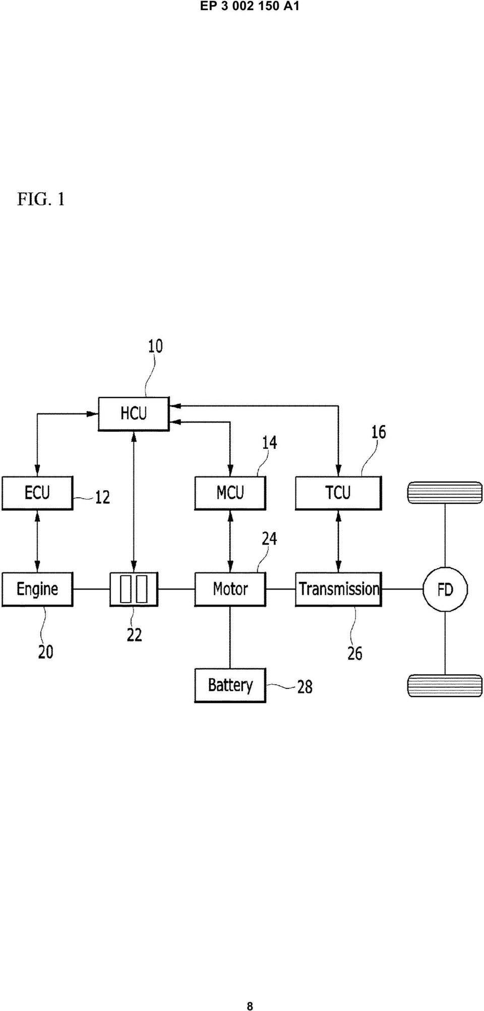
 (11) EP 2 610 763 A1 (12) EUROPEAN PATENT APPLICATION. (51) Int Cl.:") (19) TEPZZ 6_Z76 A_T (11) EP 2 6 763 A1 (12) EUROPEAN PATENT APPLICATION (43) Date of publication: 03.07.2013 Bulletin 2013/27 (51) Int Cl.: G06F 17/30 (2006.01) (21) Application number: 12192220.7 (22)
(19) TEPZZ 6_Z76 A_T (11) EP 2 6 763 A1 (12) EUROPEAN PATENT APPLICATION (43) Date of publication: 03.07.2013 Bulletin 2013/27 (51) Int Cl.: G06F 17/30 (2006.01) (21) Application number: 12192220.7 (22)
EP 2 492 881 A2 (19) (11) EP 2 492 881 A2 (12) EUROPEAN PATENT APPLICATION. (43) Date of publication: 29.08.2012 Bulletin 2012/35
 (11) EP 2 492 881 A2 (12) EUROPEAN PATENT APPLICATION. (43) Date of publication: 29.08.2012 Bulletin 2012/35") (19) (12) EUROPEAN PATENT APPLICATION (11) EP 2 492 881 A2 (43) Date of publication: 29.08.2012 Bulletin 2012/35 (51) Int Cl.: G08B 13/16 (2006.01) G08B 25/08 (2006.01) (21) Application number: 12386006.6
(19) (12) EUROPEAN PATENT APPLICATION (11) EP 2 492 881 A2 (43) Date of publication: 29.08.2012 Bulletin 2012/35 (51) Int Cl.: G08B 13/16 (2006.01) G08B 25/08 (2006.01) (21) Application number: 12386006.6
TEPZZ 94Z968A_T EP 2 940 968 A1 (19) (11) EP 2 940 968 A1 (12) EUROPEAN PATENT APPLICATION. (51) Int Cl.: H04L 29/08 (2006.01)
 (11) EP 2 940 968 A1 (12) EUROPEAN PATENT APPLICATION. (51) Int Cl.: H04L 29/08 (2006.01)") (19) TEPZZ 94Z968A_T (11) EP 2 940 968 A1 (12) EUROPEAN PATENT APPLICATION (43) Date of publication: 04.11.20 Bulletin 20/4 (1) Int Cl.: H04L 29/08 (2006.01) (21) Application number: 1430649.7 (22) Date
(19) TEPZZ 94Z968A_T (11) EP 2 940 968 A1 (12) EUROPEAN PATENT APPLICATION (43) Date of publication: 04.11.20 Bulletin 20/4 (1) Int Cl.: H04L 29/08 (2006.01) (21) Application number: 1430649.7 (22) Date
TEPZZ 65Z79 A_T EP 2 650 793 A1 (19) (11) EP 2 650 793 A1. (12) EUROPEAN PATENT APPLICATION published in accordance with Art.
 (11) EP 2 650 793 A1. (12) EUROPEAN PATENT APPLICATION published in accordance with Art.") (19) TEPZZ 65Z79 A_T (11) EP 2 650 793 A1 (12) EUROPEAN PATENT APPLICATION published in accordance with Art. 153(4) EPC (43) Date of publication: 16.10.2013 Bulletin 2013/42 (21) Application number: 12818771.3
(19) TEPZZ 65Z79 A_T (11) EP 2 650 793 A1 (12) EUROPEAN PATENT APPLICATION published in accordance with Art. 153(4) EPC (43) Date of publication: 16.10.2013 Bulletin 2013/42 (21) Application number: 12818771.3
TEPZZ 87657ZA_T EP 2 876 570 A1 (19) (11) EP 2 876 570 A1 (12) EUROPEAN PATENT APPLICATION
 (11) EP 2 876 570 A1 (12) EUROPEAN PATENT APPLICATION") (19) TEPZZ 8767ZA_T (11) EP 2 876 70 A1 (12) EUROPEAN PATENT APPLICATION (43) Date of publication: 27.0.201 Bulletin 201/22 (21) Application number: 14189809.8 (1) Int Cl.: G06F 21/34 (2013.01) G08B 13/196
(19) TEPZZ 8767ZA_T (11) EP 2 876 70 A1 (12) EUROPEAN PATENT APPLICATION (43) Date of publication: 27.0.201 Bulletin 201/22 (21) Application number: 14189809.8 (1) Int Cl.: G06F 21/34 (2013.01) G08B 13/196
TEPZZ 69 49A_T EP 2 693 349 A1 (19) (11) EP 2 693 349 A1 (12) EUROPEAN PATENT APPLICATION. (51) Int Cl.: G06F 17/30 (2006.01)
 (11) EP 2 693 349 A1 (12) EUROPEAN PATENT APPLICATION. (51) Int Cl.: G06F 17/30 (2006.01)") (19) TEPZZ 69 49A_T (11) EP 2 693 349 A1 (12) EUROPEAN PATENT APPLICATION (43) Date of publication: 0.02.2014 Bulletin 2014/06 (1) Int Cl.: G06F 17/30 (2006.01) (21) Application number: 13160696.4 (22)
(19) TEPZZ 69 49A_T (11) EP 2 693 349 A1 (12) EUROPEAN PATENT APPLICATION (43) Date of publication: 0.02.2014 Bulletin 2014/06 (1) Int Cl.: G06F 17/30 (2006.01) (21) Application number: 13160696.4 (22)
TEPZZ 84 587A_T EP 2 843 587 A1 (19) (11) EP 2 843 587 A1 (12) EUROPEAN PATENT APPLICATION. (51) Int Cl.: G06F 21/64 (2013.01)
 (11) EP 2 843 587 A1 (12) EUROPEAN PATENT APPLICATION. (51) Int Cl.: G06F 21/64 (2013.01)") (19) TEPZZ 84 87A_T (11) EP 2 843 87 A1 (12) EUROPEAN PATENT APPLICATION (43) Date of publication: 04.03.201 Bulletin 201/ (1) Int Cl.: G06F 21/64 (2013.01) (21) Application number: 13181902.1 (22) Date
(19) TEPZZ 84 87A_T (11) EP 2 843 87 A1 (12) EUROPEAN PATENT APPLICATION (43) Date of publication: 04.03.201 Bulletin 201/ (1) Int Cl.: G06F 21/64 (2013.01) (21) Application number: 13181902.1 (22) Date
EP 2 365 669 A1 (19) (11) EP 2 365 669 A1 (12) EUROPEAN PATENT APPLICATION. (43) Date of publication: 14.09.2011 Bulletin 2011/37
 (11) EP 2 365 669 A1 (12) EUROPEAN PATENT APPLICATION. (43) Date of publication: 14.09.2011 Bulletin 2011/37") (19) (12) EUROPEAN PATENT APPLICATION (11) EP 2 36 669 A1 (43) Date of publication: 14.09.11 Bulletin 11/37 (1) Int Cl.: H04L 12/8 (06.01) (21) Application number: 00243.6 (22) Date of filing:.03. (84)
(19) (12) EUROPEAN PATENT APPLICATION (11) EP 2 36 669 A1 (43) Date of publication: 14.09.11 Bulletin 11/37 (1) Int Cl.: H04L 12/8 (06.01) (21) Application number: 00243.6 (22) Date of filing:.03. (84)
TEPZZ 69 _ZA T EP 2 692 310 A2 (19) (11) EP 2 692 310 A2. (12) EUROPEAN PATENT APPLICATION published in accordance with Art.
 (11) EP 2 692 310 A2. (12) EUROPEAN PATENT APPLICATION published in accordance with Art.") (19) TEPZZ 69 _ZA T (11) EP 2 692 3 A2 (12) EUROPEAN PATENT APPLICATION published in accordance with Art. 13(4) EPC (43) Date of publication: 0.02.14 Bulletin 14/06 (21) Application number: 1276632.0 (22)
(19) TEPZZ 69 _ZA T (11) EP 2 692 3 A2 (12) EUROPEAN PATENT APPLICATION published in accordance with Art. 13(4) EPC (43) Date of publication: 0.02.14 Bulletin 14/06 (21) Application number: 1276632.0 (22)
TEPZZ 96 A_T EP 2 961 111 A1 (19) (11) EP 2 961 111 A1. (12) EUROPEAN PATENT APPLICATION published in accordance with Art.
 (11) EP 2 961 111 A1. (12) EUROPEAN PATENT APPLICATION published in accordance with Art.") (19) TEPZZ 96 A_T (11) EP 2 961 111 A1 (12) EUROPEAN PATENT APPLICATION published in accordance with Art. 13(4) EPC (43) Date of publication:.12.1 Bulletin 1/3 (21) Application number: 147426.7 (22) Date
(19) TEPZZ 96 A_T (11) EP 2 961 111 A1 (12) EUROPEAN PATENT APPLICATION published in accordance with Art. 13(4) EPC (43) Date of publication:.12.1 Bulletin 1/3 (21) Application number: 147426.7 (22) Date
EP 2 354 708 A2 (19) (11) EP 2 354 708 A2 (12) EUROPEAN PATENT APPLICATION. (43) Date of publication: 10.08.2011 Bulletin 2011/32
 (11) EP 2 354 708 A2 (12) EUROPEAN PATENT APPLICATION. (43) Date of publication: 10.08.2011 Bulletin 2011/32") (19) (12) EUROPEAN PATENT APPLICATION (11) EP 2 354 708 A2 (43) Date of publication:.08.2011 Bulletin 2011/32 (51) Int Cl.: F24H 3/08 (2006.01) F24H 8/00 (2006.01) (21) Application number: 111536.8 (22)
(19) (12) EUROPEAN PATENT APPLICATION (11) EP 2 354 708 A2 (43) Date of publication:.08.2011 Bulletin 2011/32 (51) Int Cl.: F24H 3/08 (2006.01) F24H 8/00 (2006.01) (21) Application number: 111536.8 (22)
TEPZZ 8898 7A_T EP 2 889 827 A1 (19) (11) EP 2 889 827 A1 (12) EUROPEAN PATENT APPLICATION. (51) Int Cl.: G06Q 40/04 (2012.01)
 (11) EP 2 889 827 A1 (12) EUROPEAN PATENT APPLICATION. (51) Int Cl.: G06Q 40/04 (2012.01)") (19) TEPZZ 8898 7A_T (11) EP 2 889 827 A1 (12) EUROPEAN PATENT APPLICATION (43) Date of publication: 01.07.201 Bulletin 201/27 (1) Int Cl.: G06Q 40/04 (2012.01) (21) Application number: 14199864.1 (22)
(19) TEPZZ 8898 7A_T (11) EP 2 889 827 A1 (12) EUROPEAN PATENT APPLICATION (43) Date of publication: 01.07.201 Bulletin 201/27 (1) Int Cl.: G06Q 40/04 (2012.01) (21) Application number: 14199864.1 (22)
*EP001520563A1* EP 1 520 563 A1 (19) (11) EP 1 520 563 A1 (12) EUROPEAN PATENT APPLICATION. (43) Date of publication: 06.04.2005 Bulletin 2005/14
 (11) EP 1 520 563 A1 (12) EUROPEAN PATENT APPLICATION. (43) Date of publication: 06.04.2005 Bulletin 2005/14") (19) Europäisches Patentamt European Patent Office Office européen des brevets *EP001520563A1* (11) EP 1 520 563 A1 (12) EUROPEAN PATENT APPLICATION (43) Date of publication: 06.04.2005 Bulletin 2005/14
(19) Europäisches Patentamt European Patent Office Office européen des brevets *EP001520563A1* (11) EP 1 520 563 A1 (12) EUROPEAN PATENT APPLICATION (43) Date of publication: 06.04.2005 Bulletin 2005/14
TEPZZ 9 _88_A_T EP 2 921 881 A1 (19) (11) EP 2 921 881 A1 (12) EUROPEAN PATENT APPLICATION
 (11) EP 2 921 881 A1 (12) EUROPEAN PATENT APPLICATION") (19) TEPZZ 9 _88_A_T (11) EP 2 921 881 A1 (12) EUROPEAN PATENT APPLICATION (43) Date of publication: 23.09.1 Bulletin 1/39 (21) Application number: 1416041.2 (1) Int Cl.: G01T 1/ (06.01) G03B 42/02 (06.01)
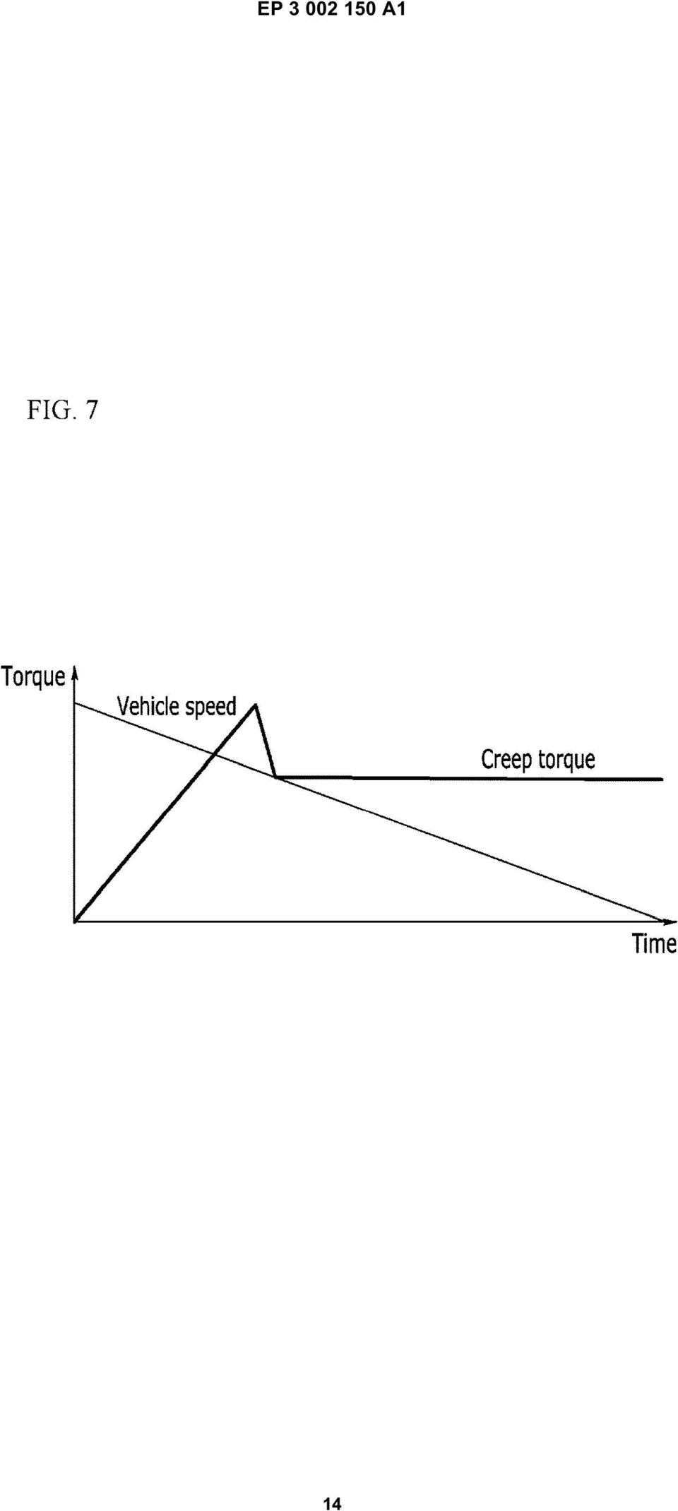
(19) TEPZZ 9 _88_A_T (11) EP 2 921 881 A1 (12) EUROPEAN PATENT APPLICATION (43) Date of publication: 23.09.1 Bulletin 1/39 (21) Application number: 1416041.2 (1) Int Cl.: G01T 1/ (06.01) G03B 42/02 (06.01)
TEPZZ 79ZZ8_A_T EP 2 790 081 A1 (19) (11) EP 2 790 081 A1 (12) EUROPEAN PATENT APPLICATION. (43) Date of publication: 15.10.2014 Bulletin 2014/42
 (11) EP 2 790 081 A1 (12) EUROPEAN PATENT APPLICATION. (43) Date of publication: 15.10.2014 Bulletin 2014/42") (19) TEPZZ 79ZZ8_A_T (11) EP 2 790 081 A1 (12) EUROPEAN PATENT APPLICATION (43) Date of publication: 1..14 Bulletin 14/42 (1) Int Cl.: G0D 23/19 (06.01) (21) Application number: 1414221.7 (22) Date of
(19) TEPZZ 79ZZ8_A_T (11) EP 2 790 081 A1 (12) EUROPEAN PATENT APPLICATION (43) Date of publication: 1..14 Bulletin 14/42 (1) Int Cl.: G0D 23/19 (06.01) (21) Application number: 1414221.7 (22) Date of
EP 1 675 420 A1 (19) (11) EP 1 675 420 A1 (12) EUROPEAN PATENT APPLICATION. (43) Date of publication: 28.06.2006 Bulletin 2006/26
 (11) EP 1 675 420 A1 (12) EUROPEAN PATENT APPLICATION. (43) Date of publication: 28.06.2006 Bulletin 2006/26") (19) Europäisches Patentamt European Patent Office Office européen des brevets (12) EUROPEAN PATENT APPLICATION (11) EP 1 67 4 A1 (43) Date of publication: 28.06.06 Bulletin 06/26 (1) Int Cl.: H04Q 7/34
(19) Europäisches Patentamt European Patent Office Office européen des brevets (12) EUROPEAN PATENT APPLICATION (11) EP 1 67 4 A1 (43) Date of publication: 28.06.06 Bulletin 06/26 (1) Int Cl.: H04Q 7/34
TEPZZ 88_898A_T EP 2 881 898 A1 (19) (11) EP 2 881 898 A1 (12) EUROPEAN PATENT APPLICATION. (51) Int Cl.: G06N 5/04 (2006.01) G06F 17/30 (2006.
 (11) EP 2 881 898 A1 (12) EUROPEAN PATENT APPLICATION. (51) Int Cl.: G06N 5/04 (2006.01) G06F 17/30 (2006.") (19) TEPZZ 88_898A_T (11) EP 2 881 898 A1 (12) EUROPEAN PATENT APPLICATION (43) Date of publication:.06. Bulletin /24 (1) Int Cl.: G06N /04 (06.01) G06F 17/ (06.01) (21) Application number: 136680.3 (22)
(19) TEPZZ 88_898A_T (11) EP 2 881 898 A1 (12) EUROPEAN PATENT APPLICATION (43) Date of publication:.06. Bulletin /24 (1) Int Cl.: G06N /04 (06.01) G06F 17/ (06.01) (21) Application number: 136680.3 (22)
Title (fr) SOURCE IONIQUE INTERNE DOUBLE POUR PRODUCTION DE FAISCEAU DE PARTICULES AVEC UN CYCLOTRON
 SOURCE IONIQUE INTERNE DOUBLE POUR PRODUCTION DE FAISCEAU DE PARTICULES AVEC UN CYCLOTRON") Title (en) A TWIN INTERNAL ION SOURCE FOR PARTICLE BEAM PRODUCTION WITH A CYCLOTRON Title (de) DOPPELTE INTERNE IONENQUELLE FÜR PARTIKELSTRAHLHERSTELLUNG MIT EINEM ZYKLOTRON Title (fr) SOURCE IONIQUE INTERNE
Title (en) A TWIN INTERNAL ION SOURCE FOR PARTICLE BEAM PRODUCTION WITH A CYCLOTRON Title (de) DOPPELTE INTERNE IONENQUELLE FÜR PARTIKELSTRAHLHERSTELLUNG MIT EINEM ZYKLOTRON Title (fr) SOURCE IONIQUE INTERNE
Our patent and trade mark attorneys are here to help you protect and profit from your ideas, making sure they re working every bit as hard as you do.
 Our patent and trade mark attorneys are here to help you protect and profit from your ideas, making sure they re working every bit as hard as you do. Our people work with everyone from multi-nationals
(51) Int Cl.: G06F 9/455 (2006.01) G06F 9/50 (2006.01)
 Int Cl.: G06F 9/455 (2006.01) G06F 9/50 (2006.01)") (19) TEPZZ 6987 B_T (11) EP 2 698 711 B1 (12) EUROPEAN PATENT SPECIFICATION (4) Date of publication and mention of the grant of the patent: 0.08.1 Bulletin 1/32 (21) Application number: 118777.8 (22) Date
(19) TEPZZ 6987 B_T (11) EP 2 698 711 B1 (12) EUROPEAN PATENT SPECIFICATION (4) Date of publication and mention of the grant of the patent: 0.08.1 Bulletin 1/32 (21) Application number: 118777.8 (22) Date
(51) Int Cl.: H04L 12/58 (2006.01) H04L 29/06 (2006.01)
 Int Cl.: H04L 12/58 (2006.01) H04L 29/06 (2006.01)") (19) TEPZZ_986 8 B_T (11) EP 1 986 382 B1 (12) EUROPEAN PATENT SPECIFICATION (4) Date of publication and mention of the grant of the patent: 19.02.14 Bulletin 14/08 (1) Int Cl.: H04L 12/8 (06.01) H04L
(19) TEPZZ_986 8 B_T (11) EP 1 986 382 B1 (12) EUROPEAN PATENT SPECIFICATION (4) Date of publication and mention of the grant of the patent: 19.02.14 Bulletin 14/08 (1) Int Cl.: H04L 12/8 (06.01) H04L
TEPZZ 799965A_T EP 2 799 965 A1 (19) (11) EP 2 799 965 A1. (12) EUROPEAN PATENT APPLICATION published in accordance with Art.
 (11) EP 2 799 965 A1. (12) EUROPEAN PATENT APPLICATION published in accordance with Art.") (19) TEPZZ 79996A_T (11) EP 2 799 96 A1 (12) EUROPEAN PATENT APPLICATION published in accordance with Art. 13(4) EPC (43) Date of publication: 0.11.14 Bulletin 14/4 (21) Application number: 14727698.4
(19) TEPZZ 79996A_T (11) EP 2 799 96 A1 (12) EUROPEAN PATENT APPLICATION published in accordance with Art. 13(4) EPC (43) Date of publication: 0.11.14 Bulletin 14/4 (21) Application number: 14727698.4
EUROPEAN PATENT APPLICATION. Hudson, NC 28638 (US) Chancery Lane London WC2A 1QU (GB)
 Chancery Lane London WC2A 1QU (GB)") (19) (12) Europaisches Patentamt European Patent Office Office europeen een des brevets EUROPEAN PATENT APPLICATION EP 0 889 344 A1 (43) Date of publication: (51) nt CI.6: G 02 B 6/44 07.01.1999 Bulletin
(19) (12) Europaisches Patentamt European Patent Office Office europeen een des brevets EUROPEAN PATENT APPLICATION EP 0 889 344 A1 (43) Date of publication: (51) nt CI.6: G 02 B 6/44 07.01.1999 Bulletin
(51) Int Cl.: G06F 11/14 (2006.01)
 Int Cl.: G06F 11/14 (2006.01)") (19) (12) EUROPEAN PATENT SPECIFICATION (11) EP 1 08 414 B1 (4) Date of publication and mention of the grant of the patent: 04.03.09 Bulletin 09/ (1) Int Cl.: G06F 11/14 (06.01) (21) Application number:
(19) (12) EUROPEAN PATENT SPECIFICATION (11) EP 1 08 414 B1 (4) Date of publication and mention of the grant of the patent: 04.03.09 Bulletin 09/ (1) Int Cl.: G06F 11/14 (06.01) (21) Application number:
EP 2 922 249 A1 (19) (11) EP 2 922 249 A1 (12) EUROPEAN PATENT APPLICATION. (43) Date of publication: 23.09.2015 Bulletin 2015/39
 (11) EP 2 922 249 A1 (12) EUROPEAN PATENT APPLICATION. (43) Date of publication: 23.09.2015 Bulletin 2015/39") (19) TEPZZ 9 49A_T (11) EP 2 922 249 A1 (12) EUROPEAN PATENT APPLICATION (43) Date of publication: 23.09. Bulletin /39 (21) Application number: 16003.0 (1) Int Cl.: H04L 12/7 (13.01) H04L 12/717 (13.01)
(19) TEPZZ 9 49A_T (11) EP 2 922 249 A1 (12) EUROPEAN PATENT APPLICATION (43) Date of publication: 23.09. Bulletin /39 (21) Application number: 16003.0 (1) Int Cl.: H04L 12/7 (13.01) H04L 12/717 (13.01)
(51) Int Cl.: H04N 7/52 (2011.01)
 Int Cl.: H04N 7/52 (2011.01)") (19) TEPZZ_9776 B_T (11) EP 1 977 611 B1 (12) EUROPEAN PATENT SPECIFICATION (4) Date of publication and mention of the grant of the patent: 16.01.13 Bulletin 13/03 (21) Application number: 0683819.1 (22)
(19) TEPZZ_9776 B_T (11) EP 1 977 611 B1 (12) EUROPEAN PATENT SPECIFICATION (4) Date of publication and mention of the grant of the patent: 16.01.13 Bulletin 13/03 (21) Application number: 0683819.1 (22)
*EP001139245A1* EP 1 139 245 A1 (19) (11) EP 1 139 245 A1 (12) EUROPEAN PATENT APPLICATION. (43) Date of publication: 04.10.2001 Bulletin 2001/40
 (11) EP 1 139 245 A1 (12) EUROPEAN PATENT APPLICATION. (43) Date of publication: 04.10.2001 Bulletin 2001/40") (19) Europäisches Patentamt European Patent Office Office européen des brevets *EP00113924A1* (11) EP 1 139 24 A1 (12) EUROPEAN PATENT APPLICATION (43) Date of publication: 04..01 Bulletin 01/ (1) Int
(19) Europäisches Patentamt European Patent Office Office européen des brevets *EP00113924A1* (11) EP 1 139 24 A1 (12) EUROPEAN PATENT APPLICATION (43) Date of publication: 04..01 Bulletin 01/ (1) Int
TEPZZ 68Z Z5A_T EP 2 680 205 A1 (19) (11) EP 2 680 205 A1 (12) EUROPEAN PATENT APPLICATION. (51) Int Cl.: G06Q 20/34 (2012.01)
 (11) EP 2 680 205 A1 (12) EUROPEAN PATENT APPLICATION. (51) Int Cl.: G06Q 20/34 (2012.01)") (19) TEPZZ 68Z ZA_T (11) EP 2 680 A1 (12) EUROPEAN PATENT APPLICATION (43) Date of publication: 01.01.14 Bulletin 14/01 (1) Int Cl.: G06Q /34 (12.01) (21) Application number: 103183.4 (22) Date of filing:
(19) TEPZZ 68Z ZA_T (11) EP 2 680 A1 (12) EUROPEAN PATENT APPLICATION (43) Date of publication: 01.01.14 Bulletin 14/01 (1) Int Cl.: G06Q /34 (12.01) (21) Application number: 103183.4 (22) Date of filing:
FEV Parallel Mode Strategy
 FEV Parallel Mode Strategy Peter Janssen MSc. Dipl.-Ing Glenn Haverkort FEV Motorentechnik As the automotive industry has to react to the global concern about climate change related to CO2 emissions and
\ \ \ connection connection connection interface interface interface
 US 20140122910A1 (19) United States (12) Patent Application Publication (10) Pub. No.: US 20140122910 A1 Chiu et al. (43) Pub. Date: May 1, 2014 (54) RACK SERVER SYSTEM AND OPERATION Publication Classi?cation
Doro PhoneEasy 331ph
 Doro PhoneEasy 331ph 1 2 6 3 4 5 English 1 Ringer indicator 2 Hanging Hook for Handset 3 Redial function 4 Volume control 5 Flash button/programming 6 Speed dial memories This device is intended for the
KINETIC ENERGY RECOVERY SYSTEM BY MEANS OF FLYWHEEL ENERGY STORAGE
 ADVANCED ENGINEERING 3(2009)1, ISSN 1846-5900 KINETIC ENERGY RECOVERY SYSTEM BY MEANS OF FLYWHEEL ENERGY STORAGE Cibulka, J. Abstract: This paper deals with the design of Kinetic Energy Recovery Systems
 HU CZ FI PL SI PT IT ES NO NL FR DK SE IE GB AT DE CH LU 0 10 20 30 40 Foreigners' share Source: Eurostat More trust 3 4 5 6 7 PL HU CZ SI PT GR ES DK FI SE
OVERVIEW OF PURCHASE AND TAX INCENTIVES FOR ELECTRIC VEHICLES IN THE EU
 01.04.2014 OVERVIEW OF PURCHASE AND TAX INCENTIVES FOR ELECTRIC VEHICLES IN THE EU This table provides an overview of the incentives that are granted in the Member States of the European Union for the
Electronic Power Control
 Service. Self-Study Programme 210 Electronic Power Control Design and Function With the Electronic Power Control system, the throttle valve is actuated only by an electric motor. This eliminates the need
7714 Evaluation 7 logic
 US 20140229045A1 (19) United States (12) Patent Application Publication (10) Pub. No.: US 2014/0229045 A1 Borchers et al. (43) Pub. Date: Aug. 14, 2014 (54) (75) (73) (21) (22) (86) (30) METHOD FOR OPERATING
ZTE Blade V Quick Start Guide
 ZTE Blade V Quick Start Guide LEGAL INFORMATION Copyright 2013 ZTE CORPORATION. All rights reserved. No part of this publication may be quoted, reproduced, translated or used in any form or by any means,
The EU Energy Tax Directive: overview about the proposed reform, impacts on national measures and state of play
 Environmentally Related Taxes and Fiscal Reform Rome, Thursday, 15 December 2011 The EU Energy Tax Directive: overview about the proposed reform, impacts on national measures and state of play A short
ERMInE Database. Presentation by Nils Flatabø SINTEF Energy Research. ERMInE Workshop 2 - Northern Europe Oslo, 1. November 2006
 ERMInE Database Presentation by Nils Flatabø SINTEF Energy Research ERMInE Workshop 2 - Northern Europe Oslo, 1. November 26 Overview Content of the Ermine Database Electronic Questionnaire RTD&D Data
TEPZZ 9 8Z87A_T EP 2 938 087 A1 (19) (11) EP 2 938 087 A1 (12) EUROPEAN PATENT APPLICATION
 (11) EP 2 938 087 A1 (12) EUROPEAN PATENT APPLICATION") (19) TEPZZ 9 8Z87A_T (11) EP 2 938 087 A1 (12) EUROPEAN PATENT APPLICATION (43) Date of publication: 28..1 Bulletin 1/44 (21) Application number: 14604.2 (1) Int Cl.: H04N 21/23 (11.01) H04N 21/488 (11.01)
(19) TEPZZ 9 8Z87A_T (11) EP 2 938 087 A1 (12) EUROPEAN PATENT APPLICATION (43) Date of publication: 28..1 Bulletin 1/44 (21) Application number: 14604.2 (1) Int Cl.: H04N 21/23 (11.01) H04N 21/488 (11.01)
CO2 BASED MOTOR VEHICLE TAXES IN THE EU IN 2015
 CO2 BASED MOTOR VEHICLE TAXES IN THE EU IN 2015 COUNTRY AT (AUSTRIA) BE (BELGIUM) BG (BULGARIA) CO2/FUEL CONSUMPTION TAXES A fuel consumption tax (Normverbrauchsabgabe or NoVA) is levied upon the first
EP 2 366 418 A2 (19) (11) EP 2 366 418 A2 (12) EUROPEAN PATENT APPLICATION. (43) Date of publication: 21.09.2011 Bulletin 2011/38
 (11) EP 2 366 418 A2 (12) EUROPEAN PATENT APPLICATION. (43) Date of publication: 21.09.2011 Bulletin 2011/38") (19) (12) EUROPEAN PATENT APPLICATION (11) EP 2 366 418 A2 (43) Date of publication: 21.09.2011 Bulletin 2011/38 (21) Application number: 11158108.8 (51) Int Cl.: A61M 5/36 (2006.01) A61M 5/315 (2006.01)
(19) (12) EUROPEAN PATENT APPLICATION (11) EP 2 366 418 A2 (43) Date of publication: 21.09.2011 Bulletin 2011/38 (21) Application number: 11158108.8 (51) Int Cl.: A61M 5/36 (2006.01) A61M 5/315 (2006.01)
US 20070139188A1 (19) United States (12) Patent Application Publication (10) Pub. No.: US 2007/0139188 A1 Ollis et al. HOME PROCESSOR /\ J\ NETWORK
 United States (12) Patent Application Publication (10) Pub. No.: US 2007/0139188 A1 Ollis et al. HOME PROCESSOR /\ J\ NETWORK") US 20070139188A1 (19) United States (12) Patent Application Publication (10) Pub. No.: US 2007/0139188 A1 Ollis et al. (43) Pub. Date: Jun. 21, 2007 (54) (75) (73) (21) (22) METHOD AND APPARATUS FOR COMMUNICATING
US 20070139188A1 (19) United States (12) Patent Application Publication (10) Pub. No.: US 2007/0139188 A1 Ollis et al. (43) Pub. Date: Jun. 21, 2007 (54) (75) (73) (21) (22) METHOD AND APPARATUS FOR COMMUNICATING
egovernment Digital Agenda Scoreboard 2014
 egovernment Digital Agenda Scoreboard 2014 1 egovernment use in EU28 has been flat In 2013 egovernment services have been used by 41% of the EU28 population, down from 44% in 2012 and almost at the same
TEPZZ 8 8 A_T EP 2 811 282 A1 (19) (11) EP 2 811 282 A1 (12) EUROPEAN PATENT APPLICATION. (51) Int Cl.: G01N 3/04 (2006.01) G01N 3/08 (2006.
 (11) EP 2 811 282 A1 (12) EUROPEAN PATENT APPLICATION. (51) Int Cl.: G01N 3/04 (2006.01) G01N 3/08 (2006.") (19) TEPZZ 8 8 A_T (11) EP 2 811 282 A1 (12) EUROPEAN PATENT APPLICATION (43) Date of publication:.12.14 Bulletin 14/0 (1) Int Cl.: G01N 3/04 (06.01) G01N 3/08 (06.01) (21) Application number: 14170412.2
(19) TEPZZ 8 8 A_T (11) EP 2 811 282 A1 (12) EUROPEAN PATENT APPLICATION (43) Date of publication:.12.14 Bulletin 14/0 (1) Int Cl.: G01N 3/04 (06.01) G01N 3/08 (06.01) (21) Application number: 14170412.2
Adaptive Cruise Control of a Passenger Car Using Hybrid of Sliding Mode Control and Fuzzy Logic Control
 Adaptive Cruise Control of a assenger Car Using Hybrid of Sliding Mode Control and Fuzzy Logic Control Somphong Thanok, Manukid arnichkun School of Engineering and Technology, Asian Institute of Technology,
60 REDIRECTING THE PRINT PATH MANAGER 1
 US006788429B1 (12) United States Patent (10) Patent No.: US 6,788,429 B1 Clough et al. (45) Date of Patent: Sep. 7, 2004 (54) REMOTE PRINT QUEUE MANAGEMENT FOREIGN PATENT DOCUMENTS (75) Inventors: James
EN 106 EN 4. THE MOBILE USE OF THE INTERNET BY INDIVIDUALS AND ENTERPRISES. 4.1. Introduction
 4. THE MOBILE USE OF THE INTERNET BY INDIVIDUALS AND ENTERPRISES 4.1. Introduction This chapter looks at mobile use of the internet by individuals and enterprises, benefiting from new data collected in
A Practical Guide to Free Energy Devices
 A Practical Guide to Free Energy Devices Device Patent No 29: Last updated: 7th October 2008 Author: Patrick J. Kelly This is a slightly reworded copy of this patent application which shows a method of
SME Instrument statistics
 SME Instrument statistics 0 beneficiaries Phase (June Sep 0), Phase (Oct 0) status January 0 SME Instrument (Horizon 00) DCC MANAGEMENT 0 SME Instrument Phase (Jun 0) beneficiaries Country breakdown Out
sparktable: Generating Graphical Tables for Websites and Documents with R
 Alexander Kowarik 1, Bernhard Meindl 1 and Matthias Templ 1,2 1. Statistics Austria 2. Vienna University of Technology Q Vienna, June, 2014 sparktable: Generating Graphical Tables for Websites and Documents
Hay (43) Pub. Date: Oct. 17, 2002
 Pub. Date: Oct. 17, 2002") US 20020152322A1 (19) United States (12) Patent Application Publication (10) Pub. No.: US 2002/0152322 A1 Hay (43) Pub. Date: Oct. 17, 2002 (54) (76) (21) (22) (51) (52) METHOD AND APPARATUS FOR FACILITATING
US 20020152322A1 (19) United States (12) Patent Application Publication (10) Pub. No.: US 2002/0152322 A1 Hay (43) Pub. Date: Oct. 17, 2002 (54) (76) (21) (22) (51) (52) METHOD AND APPARATUS FOR FACILITATING
A LIGHTWEIGHT REAR BUMPER WITH CRASH WORTHY COMPARTMENT
 1 A LIGHTWEIGHT REAR BUMPER WITH CRASH WORTHY COMPARTMENT Background of the Invention Field of the Invention This invention relates to a lightweight rear bumper with crash worthy compartment, and more
(72) Inventors: Juergen RIEDL, Koenigsbrunn (DE); USPC ( 267/285)
 Inventors: Juergen RIEDL, Koenigsbrunn (DE); USPC ( 267/285)") US 20130087957A1 (19) United States (12) Patent Application Publication (10) Pub. No.: US 2013/0087957 A1 RIEDL et al. (43) Pub. Date: Apr. 11, 2013 (54) DEVICE FOR DAMPING THE VIBRATIONS Publication Classi?cation
US 20130087957A1 (19) United States (12) Patent Application Publication (10) Pub. No.: US 2013/0087957 A1 RIEDL et al. (43) Pub. Date: Apr. 11, 2013 (54) DEVICE FOR DAMPING THE VIBRATIONS Publication Classi?cation
CHASSIS - 4WD SYSTEM. Realizes stable start-off and acceleration performance
 CH-66 CHASSIS - 4WD SYSTEM 4WD SYSTEM DESCRIPTION The 4WD system of the 06 RAV4 uses an active torque control 4WD system. It is a compact, lightweight, and high performance 4WD system that optimally controls
US 20140046812A1 (19) United States (12) Patent Application Publication (10) Pub. No.: US 2014/0046812 A1 FAN et al. (43) Pub. Date: Feb.
 United States (12) Patent Application Publication (10) Pub. No.: US 2014/0046812 A1 FAN et al. (43) Pub. Date: Feb.") US 20140046812A1 (19) United States (12) Patent Application Publication (10) Pub. No.: US 2014/0046812 A1 FAN et al. (43) Pub. Date: (54) EXPENSE REPORTS FOR PAYMENTS MADE (52) US. Cl. WITH A MOBILE DEVICE
US 20140046812A1 (19) United States (12) Patent Application Publication (10) Pub. No.: US 2014/0046812 A1 FAN et al. (43) Pub. Date: (54) EXPENSE REPORTS FOR PAYMENTS MADE (52) US. Cl. WITH A MOBILE DEVICE
EUROPEAN PATENT SPECIFICATION. (51) IntCL: G06F 13/10< 200B 1 > G06F 13/42( 2 OO 601 > (56) References cited: WO-A-97/19402 US-A- 6 085 265
 IntCL: G06F 13/10< 200B 1 > G06F 13/42( 2 OO 601 > (56) References cited: WO-A-97/19402 US-A- 6 085 265") (19) J Europäisches Patentamt European Patent Office Office européen des brevets (H) EP 1246 071 B1 (12) EUROPEAN PATENT SPECIFICATION (45) Date of publication and mention of the grant of the patent: 10.05.2006
(19) J Europäisches Patentamt European Patent Office Office européen des brevets (H) EP 1246 071 B1 (12) EUROPEAN PATENT SPECIFICATION (45) Date of publication and mention of the grant of the patent: 10.05.2006
MM, EFES EN. Marc Mathieu
 MM, EFES EN Marc Mathieu La Tribune Hewitt EUROPEAN EMPLOYEE OWNERSHIP ACROSS THE CRISIS Numbers 2006/2007/2008/2009 2009 2008 2007 2006 Employee owners 9.3 million 9.0 million 8.4 million Employees' share
US 20090157756Al (19) United States (12) Patent Application Publication (10) Pub. No.: US 2009/0157756 A1 Sanvido (43) Pub. Date: Jun.
 United States (12) Patent Application Publication (10) Pub. No.: US 2009/0157756 A1 Sanvido (43) Pub. Date: Jun.") US 20090157756Al (19) United States (12) Patent Application Publication (10) Pub. No.: US 2009/0157756 A1 Sanvido (43) Pub. Date: Jun. 18, 2009 (54) FILE SYSTEM FOR STORING FILES IN Publication Classi?cation
US 20090157756Al (19) United States (12) Patent Application Publication (10) Pub. No.: US 2009/0157756 A1 Sanvido (43) Pub. Date: Jun. 18, 2009 (54) FILE SYSTEM FOR STORING FILES IN Publication Classi?cation
(51) Int Cl.: G06F 15/16 (2006.01) G06F 9/44 (2006.01) G06F 12/00 (2006.01) G06F 9/48 (2006.01)
 Int Cl.: G06F 15/16 (2006.01) G06F 9/44 (2006.01) G06F 12/00 (2006.01) G06F 9/48 (2006.01)") (19) TEPZZ 48Z4_B_T (11) EP 2 248 041 B1 (12) EUROPEAN PATENT SPECIFICATION (4) Date of publication and mention of the grant of the patent: 29.04.1 Bulletin 1/18 (21) Application number: 0971466.8 (22)
(19) TEPZZ 48Z4_B_T (11) EP 2 248 041 B1 (12) EUROPEAN PATENT SPECIFICATION (4) Date of publication and mention of the grant of the patent: 29.04.1 Bulletin 1/18 (21) Application number: 0971466.8 (22)
European Research Council
 ERC Starting Grant Outcome: Indicative statistics Reproduction is authorised provided the source ERC is acknowledged ERCEA/JH. ERC Starting Grant: call Submitted and selected proposals by domain Submitted
SURVEY ON THE TRAINING OF GENERAL CARE NURSES IN THE EUROPEAN UNION. The current minimum training requirements for general care nurses
 SURVEY ON THE TRAINING OF GENERAL CARE NURSES IN THE EUROPEAN UNION This survey serves as a background document for the discussion of the Commission's legislative proposal to modernize the minimum requirements
TEPZZ 879 4 A_T EP 2 879 343 A1 (19) (11) EP 2 879 343 A1 (12) EUROPEAN PATENT APPLICATION. (51) Int Cl.: H04L 29/06 (2006.01)
 (11) EP 2 879 343 A1 (12) EUROPEAN PATENT APPLICATION. (51) Int Cl.: H04L 29/06 (2006.01)") (19) TEPZZ 879 4 A_T (11) EP 2 879 343 A1 (12) EUROPEAN PATENT APPLICATION (43) Date of publication: 03.06.1 Bulletin 1/23 (1) Int Cl.: H04L 29/06 (06.01) (21) Application number: 1319144.4 (22) Date of
(19) TEPZZ 879 4 A_T (11) EP 2 879 343 A1 (12) EUROPEAN PATENT APPLICATION (43) Date of publication: 03.06.1 Bulletin 1/23 (1) Int Cl.: H04L 29/06 (06.01) (21) Application number: 1319144.4 (22) Date of
M.S Ramaiah School of Advanced Studies - Bangalore. On completion of this session, the delegate will understand and be able to appriciate:
 Transmission Control Lecture delivered by: Prof. Ashok C.Meti MSRSAS-Bangalore 1 Session Objectives On completion of this session, the delegate will understand and be able to appriciate: Rl Role of electronic
Introduction to Electronic Signals
 Introduction to Electronic Signals Oscilloscope An oscilloscope displays voltage changes over time. Use an oscilloscope to view analog and digital signals when required during circuit diagnosis. Fig. 6-01
The EU s 2030 Effort Sharing Agreement
 The EU s 2030 Effort Sharing Agreement Brussels CEPS Workshop, 29.06.2015 Oliver Sartor, oliver.sartor@iddri.org Research Fellow, Climate & Energy Policy, IDDRI Celine MARCY, IDDRI Institute for Sustainable
llllllllllllllillllllllllllllllllllllllllllllllllllllllllllllllllllllllllll
 llllllllllllllillllllllllllllllllllllllllllllllllllllllllllllllllllllllllll USOO5535162A United States Patent [19] [11] Patent Number: 5,535,162 Uenoyama [45] Date of Patent: Jul. 9, 1996 [54] ELECTRICALLY
European Research Council
 ERC Advanced Grants 2011 Outcome: Indicative Statistics Reproduction is authorised provided that the source ERC is acknowledged NB: In these graphs grantee refers to a candidate selected for ERC funding
(51) Int Cl.: H02H 7/26 (2006.01) H02H 7/30 (2006.01)
 Int Cl.: H02H 7/26 (2006.01) H02H 7/30 (2006.01)") (19) TEPZZ 66ZZ_B_T (11) EP 2 66 001 B1 (12) EUROPEAN PATENT SPECIFICATION (4) Date of publication and mention of the grant of the patent: 11.03. Bulletin /11 (1) Int Cl.: H02H 7/26 (06.01) H02H 7/ (06.01)
(19) TEPZZ 66ZZ_B_T (11) EP 2 66 001 B1 (12) EUROPEAN PATENT SPECIFICATION (4) Date of publication and mention of the grant of the patent: 11.03. Bulletin /11 (1) Int Cl.: H02H 7/26 (06.01) H02H 7/ (06.01)
An Analysis of Regenerative Braking and Energy Saving for Electric Vehicle with In-Wheel Motors
 , pp. 219-23 http://dx.doi.org/1.14257/ijca.214.7.12.2 An Analysis of Regenerative Braking and Energy Saving for Electric Vehicle with In-Wheel Motors 1 Li-qiang Jin, 2 Peng-fei Chen and 3 *Yue Liu State
(54) (75) (2006.01) (73) (21) (22) (63) Peschel, Schoengeising (DE); (30) Foreign Application Priority Data. Robert Trimpe, Wessling (DE)
 (75) (2006.01) (73) (21) (22) (63) Peschel, Schoengeising (DE); (30) Foreign Application Priority Data. Robert Trimpe, Wessling (DE)") US 20120073912Al (19) United States (12) Patent Application Publication (10) Pub. No.: US 2012/0073912 A1 CAMILO-MARTINEZ et al. (43) Pub. Date: Mar. 29, 2012 (54) (75) (73) (21) (22) (63) PNEUMATICALLY
US 20120073912Al (19) United States (12) Patent Application Publication (10) Pub. No.: US 2012/0073912 A1 CAMILO-MARTINEZ et al. (43) Pub. Date: Mar. 29, 2012 (54) (75) (73) (21) (22) (63) PNEUMATICALLY
OHIM SEARCH TOOLS: TMVIEW, DSVIEW AND TMCLASS. Making trade mark and design information readily available for users
 OHIM SEARCH TOOLS: TMVIEW, DSVIEW AND TMCLASS Making trade mark and design information readily available for users Mariano Riccheri Moscow, 24 September 2015 INTERNATIONAL COOPERATION AREA European Cooperation:
THE BUSINESS VALUE OF AN ERP SYSTEM
 THE BUSINESS VALUE OF AN ERP SYSTEM AJMAL BEG THE BUSINESS VALUE OF AN ERP SYSTEM AJMAL BEG ii Copyright c 2010 by Ajmal Beg. All rights reserved. This technology described in this publication is based
DIAGNOSIS SYSTEM (3S GTE and 5S FE)
") Diagnosis System (3SGTE and 5SFE) FI39 DIAGNOSIS SYSTEM (3SGTE and 5SFE) DESCRIPTION The ECM contains a builtin, selfdiagnosis system by which troubles with the engine signal network are detected and a
Diagnosis System (3SGTE and 5SFE) FI39 DIAGNOSIS SYSTEM (3SGTE and 5SFE) DESCRIPTION The ECM contains a builtin, selfdiagnosis system by which troubles with the engine signal network are detected and a
Effects of a White Certificate trading scheme on the energy system of the EU-27
 Effects of a White Certificate trading scheme on the energy system of the EU-27 Ralf Kuder Institute of Energy Economics and the Rational Use of Energy University of Stuttgart 08.09.2009, Vienna Overview
Engine Optimization Concepts for CVT-Hybrid Systems to Obtain the Best Performance and Fuel Efficiency. Professor Andrew A. Frank Univ.
 Engine Optimization Concepts for CVT-Hybrid Systems to Obtain the Best Performance and Fuel Efficiency Professor Andrew A. Frank Univ. of CA-Davis Abstract: The objective of the advanced transmission system
EBA REPORT ON ASSET ENCUMBRANCE JUNE 2016
 EBA REPORT ON ASSET ENCUMBRANCE JUNE 2016 1 Contents List of figures 3 Executive summary 4 Analysis of the asset encumbrance of European banks 6 Sample 6 Scope of the report 6 Total encumbrance 7 Encumbrance
(51) Int Cl.: G10L 15/26 (2006.01)
 Int Cl.: G10L 15/26 (2006.01)") (19) TEPZZ Z 8B_T (11) EP 2 023 338 B1 (12) EUROPEAN PATENT SPECIFICATION (4) Date of publication and mention of the grant of the patent: 28.0.14 Bulletin 14/22 (1) Int Cl.: GL /26 (06.01) (21) Application
(19) TEPZZ Z 8B_T (11) EP 2 023 338 B1 (12) EUROPEAN PATENT SPECIFICATION (4) Date of publication and mention of the grant of the patent: 28.0.14 Bulletin 14/22 (1) Int Cl.: GL /26 (06.01) (21) Application
A Practical Guide to Free Energy Devices
 A Practical Guide to Free Energy Devices Part PatE21: Last updated: 15th January 2011 Author: Patrick J. Kelly This patent describes methods for altering HHO gas so that it can be used in vehicle engines
Open Source 100kW Electric Vehicle Controller/Inverter
 Open Source 100kW Electric Vehicle Controller/Inverter To be used with an AC Induction Motor Description By Tony Ahmann Abstract The Open Source 100kW Electric Vehicle Controller/Inverter acts as the bridge
Study on a Performance of the xev s core parts using a Real-time Monitoring System
 EVS27 Barcelona, Spain, November 17-20, 2013 Study on a Performance of the xev s core parts using a Real-time Monitoring System Mingyung Shin 1, Kiyun Jeong 1 and Inbeom Yang 1 1 Intelligent Vehicle Control
GDP per capita, consumption per capita and comparative price levels in Europe
 Economy and finance Author: Lars SVENNEBYE Statistics in focus 2008 GDP per capita, consumption per capita and comparative price levels in Europe Final results for 2005 and preliminary results for 2006
DHL Door-To-More UNLOCKING THE POTENTIAL OF DIRECT DISTRIBUTION
 DHL Door-To-More UNLOCKING THE POTENTIAL OF DIRECT DISTRIBUTION 2 DHL Door-To-More TM DHL Door-To-More 3 DHL DOOR-TO-MORE The seamless intercontinental door-to-door distribution solution that delivers
Planetary Module for Hybrid and Plug-In Hybrid vehicles
 Planetary Module for Hybrid and Plug-In Hybrid vehicles FEV e-pgs, the one fits all solution? Shanghai, September 17 th 2015 P. Janssen MSc, FEV GmbH 1 Introduction 1487 Leonardo da Vinci Helicopter 1900
CONTINUOUSLY VARIABLE TRANSMISSION (CVT)
") GROUP 23 CONTINUOUSLY VARIABLE TRANSMISSION (CVT) CONTENTS CVT........................... 23-2 GENERAL INFORMATION............. 23-2 ELECTRONIC CONTROL SYSTEM...... 23-3 EEPROM...........................
GROUP 23 CONTINUOUSLY VARIABLE TRANSMISSION (CVT) CONTENTS CVT........................... 23-2 GENERAL INFORMATION............. 23-2 ELECTRONIC CONTROL SYSTEM...... 23-3 EEPROM...........................
A revolutionary election: The Italian party system is the most simplified in Europe
 A revolutionary election: The Italian party system is the most simplified in Europe Luigi Di Gregorio 5 June 2014 1 The Italian party system has always been described as characterized by an excessive number
Your first EURES job. Progress Summary 2014Q4. March 2015
 Progress Summary 04Q4 March 05 This summary presents an overview of the implementation of Your first Eures job since the start date of activities in June 0 until the end of 04. It highlights in particular
European developments in VET Quality Assurance
 Sophie Weisswange DGVT meeting European developments in VET Quality Assurance Dublin 22-23 May 2013 EQAVET EQAVET list of indicators Underlying objectives: Better employability Better match between training
(51) Int Cl.: G06F 21/56 (2013.01)
 Int Cl.: G06F 21/56 (2013.01)") (19) TEPZZ 47 4 B_T (11) EP 2 472 42 B1 (12) EUROPEAN PATENT SPECIFICATION (4) Date of publication and mention of the grant of the patent: 16.09. Bulletin /38 (1) Int Cl.: G06F 21/6 (13.01) (21) Application
(19) TEPZZ 47 4 B_T (11) EP 2 472 42 B1 (12) EUROPEAN PATENT SPECIFICATION (4) Date of publication and mention of the grant of the patent: 16.09. Bulletin /38 (1) Int Cl.: G06F 21/6 (13.01) (21) Application
Identification and tracking of persons using RFID-tagged items
 Page 1 of 9 Identification and tracking of persons using RFID-tagged items Abstract ( 1 of 1 ) United States Patent Application 20020165758 Kind Code A1 Hind, John R. ; et al. November 7, 2002 A method
(Us) (73) Assignee: Avaya Technology Corp. Je?' McElroy, Columbia, SC (US); (21) Appl. No.: 10/413,024. (22) Filed: Apr. 14, 2003 (57) ABSTRACT
 (73) Assignee: Avaya Technology Corp. Je?' McElroy, Columbia, SC (US); (21) Appl. No.: 10/413,024. (22) Filed: Apr. 14, 2003 (57) ABSTRACT") US 20040202300A1 (19) United States (12) Patent Application Publication (10) Pub. No.: US 2004/0202300 A1 Cooper et al. (43) Pub. Date: Oct. 14, 2004 (54) CALL HANDLING USING NON-SPEECH CUES VIA A PERSONAL
US 20040202300A1 (19) United States (12) Patent Application Publication (10) Pub. No.: US 2004/0202300 A1 Cooper et al. (43) Pub. Date: Oct. 14, 2004 (54) CALL HANDLING USING NON-SPEECH CUES VIA A PERSONAL
Electronic Diesel Control EDC 16
 Service. Self-Study Programme 304 Electronic Diesel Control EDC 16 Design and Function The new EDC 16 engine management system from Bosch has its debut in the V10-TDI- and R5-TDI-engines. Increasing demands
TOYOTA ELECTRONIC CONTROL TRANSMISSION
 Electronic Control Transmission (ECT) The Electronic Control Transmission is an automatic transmission which uses modern electronic control technologies to control the transmission. The transmission itself,
2015 Half Year Results Conference Call Presentation. 26 August 2015
 2015 Half Year Results Conference Call Presentation 26 August 2015 1 Today s Call Participants Dr Patrik De Haes - CEO Dominique Vanfleteren CFO 2 Agenda for the Call 2015 Highlights US update : objectives
A Practical Guide to Free Energy Devices
 A Practical Guide to Free Energy Devices Electrolysis Patents No. 16: Last updated: 30th September 2006 Author: Patrick J. Kelly The major difficulty in using Stan s low-current Water Fuel Cell (recently
(51) Int Cl.: B29C 41/20 (2006.01) F21S 4/00 (2006.01) H05K 3/28 (2006.01)
 Int Cl.: B29C 41/20 (2006.01) F21S 4/00 (2006.01) H05K 3/28 (2006.01)") (19) TEPZZ 68698B_T (11) EP 2 68 698 B1 (12) EUROPEAN PATENT SPECIFICATION (4) Date of publication and mention of the grant of the patent: 18.11.201 Bulletin 201/47 (21) Application number: 11808612.3
(19) TEPZZ 68698B_T (11) EP 2 68 698 B1 (12) EUROPEAN PATENT SPECIFICATION (4) Date of publication and mention of the grant of the patent: 18.11.201 Bulletin 201/47 (21) Application number: 11808612.3