Consumer Information. FCC Notice
|
|
|
- Aubrie Robertson
- 8 years ago
- Views:
Transcription
1
2 Consumer Information FCC Notice This equipment has been tested and found to comply with the limits for a Class B digital device, pursuant to Part 15 of the FCC Rules. These limits are designed to provide reasonable protection against harmful interference in a residential installation. This equipment generates, uses and can radiate radio frequency energy and, if not installed and used in accordance with the instructions, may cause harmful interference to radio communications. However, there is no guarantee that interference will not occur in a particular installation. If interference generated by this unit is suspected, call Brink s Customer Care at If this equipment does cause harmful interference to radio or television reception, which can be determined by turning the equipment off and on, the user is encouraged to try to correct the interference by one or more of the following measures: Re-orient the radio/television antenna; Move the television or receiver away from the unit. Plug the unit and the TV/radio receiver into different outlets, i.e. not on the same circuit breaker. Contact Brinks Home Security or an experienced TV/Radio technician for additional suggestions. Review additional instructions on This equipment complies with FCC Rules, Part 68. On the outside of this equipment is a label that contains, among other information, the FCC Registration Number and Ringer Equivalence Number (REN) for this equipment. If requested, provide this information to your telephone company. This equipment is equipped with a USOC RJ31X connector. This equipment is designed to be connected to the telephone network or premises wiring using a compatible modular jack (RJ31X) which is part 68 compliant. The REN is useful to determine the quantity of devices you may connect to your telephone line and still have all of those devices ring when your number is called. In most, but not all areas, the sum of the REN's of all devices should not exceed five (5.0). To be certain of the number of devices you may connect to your line, as determined by the REN, you should call your local telephone company to determine the maximum REN for your calling area. Should you experience trouble with the telephone lines, disconnect the equipment from the line to determine the source of the trouble. If it is determined that the equipment is malfunctioning, discontinue its use until the malfunction has been corrected. Any repairs or alterations made by the user to this equipment, or equipment malfunctions, may give the telephone company cause to request the user to disconnect the equipment. If you experience trouble with this equipment, please contact Brink s Home Security Customer Care at for information on obtaining service or repairs, or visit and select the Frequently Asked Questions link. Should this equipment causes harm to the telephone network, the telephone company may temporarily discontinue your service. If possible, they will provide you with advance notice. Otherwise they will notify you as soon as possible. The telephone company will also advise you of changes in its facilities, equipment, operations or procedures which could affect the operation of your equipment, allowing you the opportunity to maintain uninterrupted service. You will also be advised of your right to file a complaint with the FCC. ii

3 This equipment must not be used on party lines or coin-operated phone lines. Industry Canada NOTICE: The Industry Canada label identifies certified equipment. This certification means that the equipment meets certain telecommunications network protective, operational and safety requirements as prescribed in the appropriate Terminal Equipment Technical Requirements documents. The Department does not guarantee the equipment will operate to the user's satisfaction. Before installing this equipment, users should ensure that it is permissible to be connected to the facilities of the local telecommunications company. The equipment must be installed using an acceptable method of connection. The customer should be aware that compliance with the above conditions may not prevent the degradation of service in some situations. Repairs to certified equipment should be coordinated by a representative designated by the supplier. Any repairs or alterations made by the user to this equipment, or equipment malfunctions may give the telecommunications company cause to request the user to disconnect the equipment. Users should ensure for their own protection that the electrical ground connections of the power utility, telephone lines and internal metallic water pipe system, if present, are connected together. This precaution may be particularly important in rural areas. Caution: Users should not attempt to make such connections themselves, but should contact the appropriate electric inspection authority, or electrician, as appropriate. NOTICE: The Ringer Equivalence Number (REN) assigned to each terminal device provides an indication of the maximum number of terminals allowed to be connected to a telephone interface. The termination on an interface may consist of any combination of devices subject only to the requirement that the sum of the Ringer Equivalence Numbers of all the devices does not exceed 5. This Class B digital apparatus Complies with Canadian ICES-003. Cet appareil numérique de la classe B est conforme á la norme NMB-003 du Canada. Visit or contact Brink s Customer Care at for information on obtaining service or repairs. Certification Number: A. iii

4 Table of Contents Consumer Information...ii FCC Notice...ii Industry Canada...iii Welcome...2 How to Avoid False Alarms...3 The Brink s Home Security System...4 Standard Equipment...4 Optional Equipment...6 Optional Features...7 The Parts of the Keypad...2 Status Display (Standard Keypad)...4 Message Window (Premium Keypad)...4 Emergency Keys...5 Using The Keypad...6 User Codes...7 Entering and Exiting...7 Designated Doors...7 Entry Delay...7 Exit Delay...7 Turning the System On...8 The Four On Modes...8 Turning the System On in Normal Mode...9 Turning the System On with Motions Turned Off Mode...9 Turning the System On with Motions Turned Off / Instant Mode...10 Turning the System On in Instant Mode...10 Turning the System On When It Is Not Ready...11 Turning the System Off...13 Turning the System Off When No Alarms Are In Progress...13 Turning the System Off and Canceling an Alarm...13 Turning the System Off Without Canceling an Alarm...14 What to Do in an Actual Emergency...14 Turning the System Off After an Alarm in Your Absence...15 System Options...16 How to Bypass a Zone...16 How to Turn the Door Chime On or Off...17 How to View Alarm Memory...17 How to Add an Auxiliary Code...19 How to Delete an Auxiliary Code...21 System Testing...22 Siren and Transmission Test...22 Testing All Burglary Sensors...23 Testing the Smoke Detector...24 Testing the Doors and Windows Only...24 Testing With Not Ready Zones...26

5 Trouble Messages...27 Standard Keypad...27 Premium Keypad...27 No AC Power Indication...28 Low Battery Indication...29 Communication Problem Indication...30 Line Cut Indication (Optional Feature)...31 Upload/Download Failure...31 Zone Trouble Indication...32 Component Failure...32 Call Brink s Indication...32 Siren Failure Indication...32 Keypad Not Working (Speaker Clicks)...32 If You Trigger an Alarm while Cleaning the Detector...33 Service the Detector Every Two Years...33 Setting the Clock...34 Emergency Evacuation Plans...34 Questions and Answers...36 General Use of the System...36 Codes and Code Words...37 Alarms and Emergencies...38 Emergency Contacts...38 Financial Questions...39 Repairs and Upgrades...41 Additional Questions?...41 Warranty Information...41 Important Notices...42

6 Welcome Thank you for choosing Brink s Home Security. We appreciate your business. To get the most from the easy-to-use Brink s Home Security System, please take the time to read this manual. It describes the components of the system, and tells you how to use the keypad. It also tells you what to do in the event of an alarm. Also, be sure to read your Customer Emergency Information Schedule so that you will have a clear understanding of Brink s procedures if you should have an alarm. If you have any questions about the security system, visit or call Brink s Customer Care at Customer Care is ready to help you 24 hours a day, seven days a week. 2

7 How to Avoid False Alarms Numerous false alarms can affect the quality of your monitoring service. They can also result in fines from your local municipality. To avoid false alarms, follow these simple tips: 1. Be sure that everyone in your house knows how to use the alarm system. Everyone should know a user code and the code word. You can use the interactive keypad at to practice turning the system on and off without causing an alarm. 2. If you cause an alarm accidentally, cancel it by entering your user code and pressing the CANCEL key. (See page 13.) 3. Test the system every week, following the instructions beginning on page 22. If you discover any problems, promptly notify Brink s Customer Care at If there was an alarm on the system, and you do not know why it happened, contact Brink s Customer Care immediately. You may also review the system s alarm history at 5. If you are going to do any kind of work at your home that will create a large amount of dust, (such as fumigation), completely cover the system s motion detectors and smoke/heat detectors. Be sure to remove the covers when you are finished. 6. If you know that the motion detector is causing false alarms, you can still turn the system on, while the motion detector is turned off. See the instructions on page 9 (Turning the System On with Motions Turned Off Mode). Promptly notify Brink s Customer Care to correct the problem. 7. If you get an indoor pet after the system is installed, contact Brink s Customer Care. The system s motion detector may need to be adjusted so that your pet does not cause a false alarm. 8. Motion detectors can detect the movement of balloons, plants, curtains, and other common household objects. Be sure that air currents cannot move these items into the area covered by the motion detector. 9. Notify Brink s before you sell or rent out your home, so that we can teach the new residents how to use the system. Visit our website 3
 3. Test the system every week, following the instructions beginning on page 22.")
8 at to get more information about our Customer Move Program. 10. Take care when cooking or lighting a fire in the fireplace. Excessive smoke from these activities can cause false alarms. The Brink s Home Security System Standard Equipment Master Control Panel The master control panel is housed in a metal box. It is mounted in an out-of-the-way location, such as a closet. The master control panel processes the information sent to it by the system s sensors and keypad. It also contains a battery that allows the system to operate during a power failure. When an alarm occurs, the master control panel sends a message over the telephone line to the Brink s Monitoring Center. Do not open the master control panel unless a Brink s representative instructs you to do so. The keypad is mounted on the wall, near an entry/exit door. You can use it to turn the system on and off, and to change other system options. Keypads come in Premium and Standard styles (see pages 2 and 3.) Keypad (Premium Style Shown) You can also use the keypad s emergency panic buttons to signal a fire, medical, or police emergency. (See page 5 for more information or review the Keypad Functions information at Door/ Window Sensors One sensor is placed in or on the frame and body of each door or window that is protected. If the door or window is opened while the system is on, an alarm sounds. An alarm signal is sent to the Brink s Monitoring Center. 4

9 Standard Equipment Motion Detector This sensor is mounted on the wall, inside your home. The sensor can detect when someone is moving within its field of view. If the system is on at the time a person is detected, the system sends an alarm signal to the Brink s Monitoring Center. Siren The siren is a small plastic box, mounted inside your home. When an alarm occurs, the siren sounds a warning, designed to frighten off intruders. The siren may also sound when you use some of the system s special features. The power transformer is plugged into an outlet near the master control panel. It provides electrical power to the system. Power Transformer If you should notice that the transformer is unplugged, plug it back in immediately. This device connects the security system to the telephone line in your home. It is located near or inside the master control panel. This makes it possible for the system to send alarm signals over the telephone lines to the Brink s Monitoring Center. Telephone Jack Do not remove the dialer cable from the jack unless a Brink s representative or this manual instructs you to do so. The highly visible sign and stickers warn potential intruders that your home is protected by a Brink s Home Security system. You will be provided with one sign and several stickers. Yard Sign and Window Stickers 5


10 Optional Equipment Smoke/Heat Detector This device detects smoke and dangerously high temperatures. It is mounted in a central location of the house, on the ceiling. Smoke/heat detectors are not available for commercial installations. Heat Sensor This device detects when the temperature near the sensor is dangerously high. It is mounted in a central location of the house, on the ceiling. Heat sensors are not available for commercial installations. This small detector is mounted near any large expanse of glass (windows or doors) in your home. It identifies the sound of breaking glass. Glass Breakage Detector The SmartKey is a small remote-control device for the security system. The four buttons on the device can be used to turn the system on and off, and to do other specialized functions, like trigger an emergency alarm. SmartKey Telephone Control Module The optional Telephone Control Module allows you to control the security system from any touch-tone telephone, whether you are at home or across the country. You can check the system s status while on vacation, or trigger an emergency alarm from your bedroom. The Telephone Control Module is also a helpful feature for visually-impaired users who may have difficulty using a traditional keypad. 6
 in your home. It identifies the sound of breaking glass.")
11 Optional Features Line Cut Pager/Latchkey If your telephone line is cut, the optional line cut feature notifies you. If the system is on, the siren sounds. If the system is off, the keypad beeps and displays a trouble message. Because a line cut results in a loss of telephone service, this event is not reported to the Brink s Monitoring Center. The optional pager/latchkey feature notifies you that your children have arrived home safely when you are away. When your child turns the system on or off, you receive a page on your pager. You can also receive pages for other system events, like alarms or power loss. For information about any of these products or services, visit or call Brink s Customer Care at Customer Care is ready to help you 24 hours a day, seven days a week. 7

12 The Parts of the Keypad 2

13 3
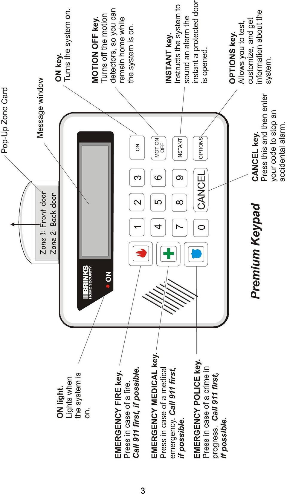
14 Status Display (Standard Keypad) The illustration below shows the functions of the keypad s lights. Message Window (Premium Keypad) The Premium Keypad communicates with you by lighting the words and phrases in the message window. The words that make up the message may be on different lines, or separated by other words. For example, while you are changing an auxiliary user code, you will see the following message window: The words ENTER and NEW CODE are lit. This means that you should enter the new user code. 4

15 Emergency Keys If you are home when a police, medical, or fire emergency arises, you can alert the Brink s Monitoring Center of your situation with a single press of an emergency key. The system does not need to be on. (Not all emergency buttons are available to all commercial customers.) The table shows what purpose each key serves, and what happens when it is pressed. (Depending upon how the system is programmed, you may need to press the emergency key twice within three seconds to signal an emergency alarm.) Emergency Press This happens Fire The siren sounds and a signal is sent to the Brink s Monitoring Center. Brink s calls the fire department, and then calls you to verify the alarm. (This procedure may vary in some jurisdictions.) Medical The keypad beeps and a signal is sent to the Brink s Monitoring Center. Brink s calls you to verify the alarm. If for any reason you do not answer that call, Brink s calls emergency personnel. Police The siren sounds and a signal is sent to the Brink s Monitoring Center. Brink s calls you to verify the alarm. If for any reason you do not answer that call, Brink s calls emergency personnel. CALL 911 FIRST If your community provides 911 Emergency service, and you are able to reach a telephone during the emergency, Brink s recommends that you call 911 before pressing the emergency key. This gives you the fastest access to emergency services. If you press an emergency key accidentally, cancel the alarm by pressing the CANCEL key, and entering your user code. (For more information about canceling alarms, see page 13, or review the Reduce False Alarms information at 5
 Emergency Press This happens Fire The siren sounds and a signal is sent to the Brink s Monitoring Center. Brink s calls the fire department, and then calls you to verify the alarm.")
16 Using The Keypad The Brink s Home Security system in your home may have a Standard Keypad, or a Premium Keypad. Both types of keypads can be used to turn the system on or off, or to test or customize it. For some procedures, the keypads commands are slightly different. In those cases, this manual contains two sets of instructions, like those shown below. If you are using a Standard Keypad, follow the instructions on the left. If you are using a Premium Keypad, follow the instructions on the right. If the keypad looks like this: If the keypad looks like this: Follow the instructions for the Standard Keypad Follow the instructions for the Premium Keypad 1. Press the OPTONS key. 1. Observe the number displayed in the message window. This is the zone that is not ready. (There may be more than one.) 2. Press the 7 key. 2. Refer to the Pop- Up Zone Card to verify the location of the zone. 6

17 User Codes When the system is installed, you select a code number to turn the system on and off. This is your master user code, and it may be three or four digits long. To change this code, contact Brink s Customer Care at You can create a separate auxiliary user code for anyone who needs access to your home. See page 19 for more information. You can change or delete the auxiliary code whenever you like. If you have questions about the system s user codes, visit our website or contact Brink s Customer Care. Entering and Exiting Designated Doors The designated entry/exit doors are those doors that you must use to enter and leave your home while the system is on. These doors may be equipped with the door sensors described on page 4. If you use a different door to enter your home, an alarm may sound. Entry Delay When you enter your home while the security system is on, the keypad beeps. This beeping reminds you to turn the system off. You must enter your user code before the beeping stops. In most systems, that delay is 40 seconds long. If you do not enter your code before the delay ends, an alarm is triggered. Exit Delay When you turn the system on in normal mode, you must exit the building and close the door before the exit delay ends. For most systems, the exit delay is 80 seconds; however, that number may vary if local agency or regulator restrictions apply. Once that delay has ended, you will trigger an alarm if you open a protected door or window, or move past a motion detector. Note: The length of the system s entry and exit delays can be adjusted (within certain limits). If you find it difficult to enter or exit your home 7

18 before the delay ends, contact Brink s Customer Care at to have it changed. Turning the System On The Four On Modes You can arm the Brink s Home Security system in four different ways: 1) normal mode; 2) motion off; 3) motions off with delay doors instant; and 4) delay doors instant. The illustration below helps you choose which mode to use. 8
 delay doors instant.")
19 Turning the System On in Normal Mode 1. Close all of the doors and windows and make sure that the message window reads READY or the READY light is lit. (If not, see page 11.) 2. Press the ON key. The ON light begins to blink, telling you that the system is on and that the exit delay has begun. The Premium Keypad displays the number of seconds left in the exit delay. 3. Exit promptly. You must leave the building before the delay ends. The standard delay is 80 seconds. If the ON light stops blinking and is steadily lit, the exit delay has ended. If you open a door now, you will cause an alarm. Turn the system off by entering your user code, then start over. Turning the System On with Motions Turned Off Mode 1. Close all of the doors and windows and make sure that the message window reads READY or the READY light is lit. (If not, see page 11.) 2. Press the ON key. 3. Press the MOTION OFF key. (You must press the MOTION OFF key no more than 20 seconds after you press the ON key.) The ON light blinks. The Premium Keypad reads ON, MOTION OFF. The Standard Keypad s MOTION OFF and ON lights are lit. 9

20 Turning the System On with Motions Turned Off / Instant Mode 1. Close all of the doors and windows and make sure that the message window reads READY or the READY light is lit. (If not, see page 11.) 2. Press the ON key. 3. Press the MOTION OFF key. 4. Press the INSTANT key. Turning the System On in Instant Mode The ON light turns on. The Premium Keypad reads ON, MOTION OFF, and INSTANT. The Standard Keypad s ON, MOTION OFF and INSTANT lights are lit. Do not leave the building, or open any protected windows without first turning the system off. 1. Close all of the doors and windows and make sure that the message window reads READY or the READY light is lit. (If not, see page 11.) 2. Press the ON key. 3. Press the INSTANT key. The ON light turns on. The Premium Keypad reads ALL ON, INSTANT. The INSTANT light of the Standard Keypad turns on. Do not leave the building, open any protected windows, or move in front of the motion detector without first turning the system off. 10
 2. Press the ON key. 3. Press the INSTANT key.")
21 Turning the System On When It Is Not Ready If the system is not ready to turn on, you get a not ready message. This message could mean, for example, that one of the protected windows in your house is open. If you have a Standard Keypad, the READY light is off. If you have a Premium Keypad, the message window reads NOT READY. If you press the ON key when the system is not ready to turn on, the keypad sounds an error tone and the system does not turn on. To make the system ready to arm and it on, do the following: 1. Press the OPTONS key. 2. Press the 7 key. 3. Observe which zone light blinks for the next five seconds. This is the zone that needs to be corrected before the system will turn on. (There may be more than one.) 4. Refer to the Pop-Up Zone Card to verify the zone s location. 1. Observe the number displayed in the message window. This is the zone that needs to be corrected before the system will turn on. (There may be more than one, if so, the numbers are shown one at a time.) 2. Refer to the Pop-Up Zone Card to verify the zone s location. 5. If the zone is a door or window, make sure that it is securely closed. 6. If the READY light illuminates, turn the system on. READ Y 3. If the zone is a door or window, make sure that it is securely closed. 4. If the message window reads READY, turn the system on. (continued) 11
22 7. If the READY light does not turn on, see the Frequently Asked Questions information at or call Customer Care at for further assistance in correcting the notready condition. 8. To turn the system on, you must first turn off the zone that is not ready to arm. Press the OPTIONS key. 9. Press the 1 key. Bypass ENTER ZONE 5. If the message window reads NOT READY, see the Frequently Asked Questions information at or call Customer Care at for further assistance in correcting the notready condition. 6. To turn the system on, you must first turn off the zone that is not ready to arm. Press the OPTIONS key until the message window reads: BYPASS, ENTER ZONE #. BYPASS ZONE NUMBER 10. Enter the number of the not-ready zone, the number of the illuminated light you observed in Step 1. CAUTION: If you bypass a zone, it will not be protected. ZONE NUMBER 7. Enter the number of the not-ready zone, the same number that appeared in the message window. CAUTION: If you bypass a zone, it will not be protected. The keypad beeps. The READY and BYPASS lights turn on. The keypad beeps. The message window reads READY, BYPASS and the number of the bypassed zone is momentarily displayed. 11. Turn the system on. 8. Turn the system on. 12
23 Turning the System Off Turning the System Off When No Alarms Are In Progress 1. Enter through a designated entry door. The keypad sounds a tone to remind you to turn the system off. The ON light blinks. 2. Turn the system off by entering your code. To prevent an alarm, you must enter your code before the entry delay ends. The standard delay is 40 seconds. The keypad beeps. Once the system is off, the ON light goes out. Turning the System Off and Canceling an Alarm Follow these instructions if you caused an alarm accidentally. 1. Enter through a designated entry door. The siren is sounding and the ON light blinks. The Premium Keypad s message window reads ALARM. The Standard Keypad s ON light blinks. 2. Enter your user code. The keypad beeps. The Premium Keypad s message window reads ALARM MEMORY. 3. Press the CANCEL key. (You must press the CANCEL key within 20 seconds of entering your code.) You will not receive a call from Brink s. The Premium Keypad s message window reads ALARM CANCELED. Note: If you press the CANCEL key before entering your code, the result is the same. 13
24 Turning the System Off Without Canceling an Alarm Follow these instructions if you wish to turn off the system and report an alarm to Brink s. 1. Enter the building through a designated entry door. The Premium Keypad s message window reads ALARM. The siren is sounding and the ON light is lit. 2. Enter your user code. What to Do in an Actual Emergency The keypad beeps. Wait for Brink s to call. Be prepared to give the Brink s operator your code word. Do not use the telephone if you intend to cancel the alarm. If your telephone line is busy, Brink s may dispatch emergency personnel to your home, which could result in a false alarm fine. If the security system is sounding an alarm, and there is an actual emergency in progress, do the following: 1. Leave the system on. If the emergency is a fire, quickly notify the building s occupants and safely evacuate the building. 2. Do not use the telephone, except to call 911. If you do, Brink s personnel may not be able to contact you. If you are trying to make a telephone call while another alarm is triggered, the system will disconnect your call to send the alarm signal. If this continues, you may need to turn the system off to use the telephone. 3. If this is a medical or police emergency, wait for Brink s to call. Explain the emergency to the operator. If you do not answer the telephone, Brink s will try to contact the appropriate emergency agency, unless you have given other instructions. 14
25 Turning the System Off After an Alarm in Your Absence Follow these instructions if there was an alarm at your house while you were away and the sirens are no longer sounding. 1. Enter the building through a designated entry door. The ON light blinks. The sirens and speakers are silent. The Premium Keypad shows the numbers of the zones in alarm and its message window reads ALARM. 2. Enter your user code to turn the system off. The keypad beeps for one second. The keypad shows the numbers of the zones that were in alarm. The Premium Keypad reads ALARM MEMORY. 3. Refer to the Pop-Up Zone Card to verify the location of the zones that were in alarm. 4. To silence the keypad s beeping and clear Alarm Memory, press the CANCEL key. 5. If you do not know what caused the alarm, review the system s alarm history at or call Brink s Customer Care at
26 System Options The system has five options: 1) bypass; 2) door chime; 3) auxiliary codes; 4) alarm memory; and 5) test. This section describes each of these five options. How to Bypass a Zone When you bypass a zone, the system ignores it. Use this whenever you want to turn the system on, but leave a particular sensor off. The bypass is automatically canceled when you turn the system off. To bypass a zone, do the following: 1. Press the OPTIONS key. 2. Press the 1 key. Bypass ENTER ZONE # 1. Press the OPTIONS key until the message window reads: BYPASS, ENTER ZONE #. BYPASS 3. Enter the number of the zone you wish to bypass. The keypad beeps. The READY and the BYPASS lights turn on. 2. Enter the number of the zone you wish to bypass. The keypad beeps. The message window reads READY, BYPASS. The number of the bypassed zone lights momentarily. 16
27 How to Turn the Door Chime On or Off When you turn the door chime on, the keypad beeps if a protected door or window is opened while the system is turned off. To turn the chime on or off, do the following: CHIME 1. Press the OPTIONS key. 2. Press the 2 key. The ENTER CODE light blinks. DOOR CHIME ENTER CODE 1. Press the OPTIONS key until the message window reads: DOOR CHIME, ENTER CODE. 3. Enter your code. 2. Enter your code. The keypad beeps. The READY and the CHIME light turns on while the chime feature is on. The keypad beeps. The message window reads READY, DOOR CHIME. Note: If you turn the door chime on and the keypad does not beep, the chime feature may have been turned off at installation. Call Customer Care for assistance. How to View Alarm Memory You can use alarm memory to determine which zones were in alarm. MEMORY 1. Press the OPTIONS key. 2. Press the 4 key. The ENTER CODE light blinks. ALARM MEMORY ENTER CODE 1. Press the OPTIONS key until the message window reads: ALARM MEMORY, ENTER CODE. 17
System User s Manual
 System User s Manual BHS-4000A Consumer Information FCC Notice This equipment has been tested and found to comply with the limits for a Class B digital device, pursuant to Part 15 of the FCC Rules. These
TABLE OF CONTENTS HOW TO AVOID FALSE ALARMS... 2
 TABLE OF CONTENTS HOW TO AVOID FALSE ALARMS... 2 THE BRINK S HOME SECURITY SYSTEM Equipment in the Standard Systems... 3 Optional Equipment... 4 Optional Features... 5 Description of the Keypad... 6 OPERATING
TABLE OF CONTENTS HOW TO AVOID FALSE ALARMS... 1
 TABLE OF CONTENTS HOW TO AVOID FALSE ALARMS... 1 THE BRINK S HOME SECURITY SYSTEM Equipment in the Standard Systems... 2 Optional Equipment... 3 Description of the Keypad... 5 OPERATING THE BRINK S SYSTEM
466-1936 Rev E October 2004 ZZZ*(6HFXULW\FRP. Part No: 60-883-95R. CareGard. User Guide
 ) *(6HFXULW\ 466-1936 Rev E October 2004 ZZZ*(6HFXULW\FRP Part No: 60-883-95R CareGard User Guide FCC Notices FCC Part 15 Information to the User Changes or modifications not expressly approved by GE Security
User s Guide. Security Systems D220
 User s Guide Security Systems D220 Table of Contents About This User s Guide... 3 Introduction... 3 Security System Basics... 4 Controlled Points... 5 24-Hour Points... 6 Keypad Keys... 6 Keypad Lights...
FIRST ALERT INSTRUCTION MANUAL FOR FA 270 KEYPADS SECURITY SYSTEM
 FIRST ALERT INSTRUCTION MANUAL FOR FA 270 KEYPADS SECURITY SYSTEM Page 0 Table of Contents Introduction 1 System Basics.. 1 Burglary Protection.. 1 Fire Protection.. 1 Security Codes. 1 Zones and Partitions
SECURITY SYSTEM NOTES
 SECURITY SYSTEM NOTES Installing/Service Company For Service Call Central Station Duress Code FUNCTION CODES Function Code Controls Function This system is is not partitioned. EMERGENCY ACTIVATION KEYS
NetworX NX-6V2. LED Keypad User Manual
 NetworX NX-6V2 LED Keypad User Manual POWER Light is on when AC power is present; flashes to indicate a low battery condition. ARMED Light is on when armed; off when disarmed; flashes to indicate a previous
SECURITY SYSTEM NOTES
 SECURITY SYSTEM NOTES Installing/Service Company For Service Call Central Station Duress Code FUNCTION CODES Function Code Controls Function EMERGENCY ACTIVATION KEYS (check if enabled) Fire Auxiliary
INSTRUCTION MANUAL DSC 1550
 INSTRUCTION MANUAL DSC 1550 A WORD ABOUT YOUR SYSTEM The PC1550 Security System has been designed to give you the greatest possible flexibility and convenience. Read this manual carefully and become familiar
SPECIAL CODES AUXILIARY CODES SYSTEM NOTES
 Installing/Service Company Monitoring Center SPECIAL CODES Master Code Duress Code AUXILIARY CODES "Quick Arm" " Chime" 08 02 09 03 10 04 11 05 12 06 13 07 14 SYSTEM NOTES Exit Delay Time Entry Delay Time
INSTRUCTION MANUAL PC255O
 INSTRUCTION MANUAL PC255O Canadian Department of Communications Notice NOTICE: The Canadian Department of Communications label identifies certified equipment. This certification means that the equipment
GE Concord 4 Quick User Guide
 GE Concord 4 Quick User Guide GE Concord 4 Quick User Guide Page 1 Before Calling Is the keypad beeping? Press *. This will silence the beeping and let you know where the trouble is. Is there a flashing
SECURITY SYSTEM NOTES SPECIAL CODES AUXILIARY ARM / DISARM CODES ENTRY / EXIT DELAY TIMES ZONE DESCRIPTIONS
 SECURITY SYSTEM NOTES Installing/Service Company For Service Call SPECIAL CODES Master Code Duress Code "Quick Arm" Digit "Chime" Digit "Entry-Guard" Digit AUXILIARY ARM / DISARM CODES 02 12 22 03 13 23
HILLS Series LED Code Pad User Manual
 HILLS Series LED Code Pad User Manual Not all features may be available on your system Check with your installer to find out which features are programmed Page 2 TABLE OF CONTENTS Code Pad Diagrams...2
SECURITY SYSTEM NOTES SPECIAL CODES ENTRY / EXIT DELAY TIMES ARM / DISARM CODES
 SECURITY SYSTEM NOTES Installing/Service Company For Service Call SPECIAL CODES "Chime" Digit 1 "Partial Arm" Digit 2 "Quick Arm" Digit 3 ENTRY / EXIT DELAY TIMES Exit Delay Time Entry Delay Time Secondary
SECURITY SYSTEM NOTES SPECIAL CODES. Security System Configuration
 Installing / Service Company: SECURITY SYSTEM NOTES For Service Call: Master Code SPECIAL CODES Duress Code Security System Configuration Auxiliary Code(s) Quick Arm" Digit: 2 9 3 10 4 11 5 12 6 13 7 14
HILLS Series LED Code Pad User Manual
 HILLS Series LED Code Pad User Manual Not all features may be available on your system Check with your installer to find out which features are programmed Page 2 TABLE OF CONTENTS Code Pad Diagrams...2
SECURITY SYSTEM NOTES. Security System Configuration
 Installing / Service Company: For Service Call: SECURITY SYSTEM NOTES Security System Configuration Master Code: Auxiliary Code(s) 2 3 4 5 6 "Quick Arm" Digit: Exit Delay Time Auxiliary Exit Delay Time
www.ealarm.com.my P/N 5-051-371-00 Rev D
 System 236 System 236i P/N 5-051-371-00 Rev D Thank you for purchasing this C&K alarm system Your system is one of the most powerful and advanced alarm systems on the market today, designed to provide
Using your LED Plus keypad
 Using your LED Plus keypad System 238 System 2316 System 238i System 2316i Part Number 5-051-372-00 Rev B Thank you for purchasing this C&K alarm system Your system is one of the most powerful and advanced
P/N 5-051-371-00 Rev D
 System 236 System 236i P/N 5-051-371-00 Rev D Thank you for purchasing this C&K alarm system Your system is one of the most powerful and advanced alarm systems on the market today, designed to provide
Using your LED Plus keypad
 Using your LED Plus keypad System 238 System 2316 System 238i System 2316i Part Number 5-051-372-00 Rev B Thank you for purchasing this C&K alarm system Your system is one of the most powerful and advanced
INSTRUCTION MANUAL PC5OO WITH PC5OORK KEYPAD
 INSTRUCTION MANUAL PC5OO WITH PC5OORK KEYPAD TABLE OF CONTENTS SYSTEM INFORMATION 2 INTRODUCTION 3 Test Your System Regularly...3 Important Notice...3 Glossary...3 BASIC OPERATION 4 Arming Your System...4
Personal Assistance System Owner's Guide
 Owner's Guide PSC07 READ THIS FIRST This equipment generates and uses radio frequency energy, and if not installed and used properly, that is, in strict accordance with the manufacturers instructions,
Changes or modifications not expressly approved by Interlogix, Inc. can void the user s authority to operate the equipment.
 9-4 5 ) 7 ) 8 A HI E = @ = JA H 6 D A 2 A =? A A A F A H 1 FCC Notices FCC Part 15 Information to the User Changes or modifications not expressly approved by Interlogix, Inc. can void the user s authority
Using your Alpha Plus keypad With your
 Using your Alpha Plus keypad With your q q q System 236 System 238 System 2316 q q q System 236i System 238i System 2316i Part Number 5-051-373-00 Rev B Thank you for purchasing this C&K alarm system Your
User s Guide. Security Systems
 User s Guide Security Systems National Security Systems Inc (800)457-1999 2 Table of Contents About This Users Guide... 4 Introduction... 4 Security System Basics... 5 Controlled Points... 6 24-Hour Points...
User s Guide. Security Systems
 User s Guide Security Systems 2 Table of Contents About This Users Guide... 4 Introduction... 4 Security System Basics... 5 Controlled Points... 6 24-Hour Points... 7 Keypad Keys... 7 Keypad Tones... 8
NetworX Series. NX- 4/8 Code Pad. User Manual (Australian Version)
") NetworX Series NX- 4/8 Code Pad User Manual (Australian Version) Table Of Contents Code Pad Diagram... Inside Front Glossary of Terms...2 Understanding the Code Pad lights...3 Code Pad Tones...4 Fully
NetworX Series NX- 4/8 Code Pad User Manual (Australian Version) Table Of Contents Code Pad Diagram... Inside Front Glossary of Terms...2 Understanding the Code Pad lights...3 Code Pad Tones...4 Fully
SECURITY SYSTEM NOTES. EMERGENCY ACTIVATION KEYS (check if enabled) PROGRAMMED FUNCTIONS
 PROGRAMMED FUNCTIONS") SECURITY SYSTEM NOTES Installing/Service Company For Service Call Installation Date / / Central Station Duress Code EMERGENCY ACTIVATION KEYS (check if enabled) Fire Auxiliary Emergency Police PROGRAMMED
SECURITY SYSTEM NOTES Installing/Service Company For Service Call Installation Date / / Central Station Duress Code EMERGENCY ACTIVATION KEYS (check if enabled) Fire Auxiliary Emergency Police PROGRAMMED
GC2 Panel User Guide
 GC2 Panel User Guide ENGLISH (International) WIRELESS SECURITY SYSTEM WARNING: OWNER S I NSTRUCTION NOTICE Not to be removed by anyone except occupant THIS PAGE INTENTIONALLY LEFT BLANK CONTENTS System
INSTRUCTION MANUAL. DSC Security Products PC1500/PCI550
 INSTRUCTION MANUAL DSC Security Products PC1500/PCI550 ABOUT YOUR SECURITY SYSTEM Your DSC security equipment has been designed to give you the greatest possible flexibility and convenience. Read this
INSTRUCTION MANUAL SOFTWARE VERSION 1.0R
 INSTRUCTION MANUAL SOFTWARE VERSION 1.0R FCC COMPLIANCE STATEMENT CAUTION: Changes or modifications not expressly approved by Digital Security Controls Ltd. could void your authority to use this equipment.
National Security Systems Inc (800)457-1999. Security System User's Guide
457-1999. Security System User's Guide") National Security Systems Inc (800)457-1999 Security System User's Guide Security System Glossary As security system technology has evolved, a special jargon has developed. Some terms widely used within
National Security Systems Inc (800)457-1999 Security System User's Guide Security System Glossary As security system technology has evolved, a special jargon has developed. Some terms widely used within
SECURITY SYSTEM NOTES AREA LISTINGS SPECIAL CODES ENTRY / EXIT DELAY TIMES ARM / DISARM CODES ZONE DESCRIPTIONS
 SECURITY SYSTEM NOTES Installing/Service Company For Service Call Area 1 Area 2 Area 3 AREA LISTINGS SPECIAL CODES "Quick Arm" Digit "Partial Arm" Digit "Chime" Digit ENTRY / EXIT DELAY TIMES Exit Delay
Changes or modifications not expressly approved by Interactive Technologies, Inc. can void the user s authority to operate the equipment.
 0 FCC Notices FCC Part 15 Information to the User Changes or modifications not expressly approved by Interactive Technologies, Inc. can void the user s authority to operate the equipment. FCC Part 15 Class
SECURITY & MONITORING QUICK GUIDE
 SECURITY & MONITORING QUICK GUIDE Now that you have your security system installed, use it regularly. Regular usage will increase your comfort with operating the system and reduce the likelihood of false
Users Guide to Keypad Functions
 Users Guide to Keypad Functions MANUAL NO. 700-175-01J ISSUED JAN 2002 VERSION 1.41 Summary of Operation A rm/ disarm [#] + [USER CODE] Quick Quick Quick Panic Fire Medical Away Arm Stay Arm Stay Arm &
City of Temple Burglar Alarm Permit Process Information Sheet
 City of Temple Burglar Alarm Permit Process Information Sheet Initial Permit FREE Renewal Permit Fee $ 10.00 -EVERY TWO YEARS Make checks / money orders payable to: The City of Temple, FARP Mail to: Temple
IDS. Users Guide to Keypad Functions S E C U R I T Y MANUAL NO. 700-171-01B ISSUED AUG 2002 VERSION 1.18
 INHEP DIGITAL IDS S E C U R I T Y Users Guide to Keypad Functions MANUAL NO. 700-171-01B ISSUED AUG 2002 VERSION 1.18 Summary of Operation A rm/ disarm [#] + [USER CODE] Quick Quick Quick Away Arm Stay
616, 626, 636 & 646 Keypads
 616, 626, 636 & 646 Keypads User s Manual TABLE OF CONTENTS 1.0 BASIC OPERATION...2 2.0 ACCESS CODES...4 3.0 ARMING & DISARMING...6 4.0 PANIC ZONES...13 5.0 KEY ACCESS PROGRAMMING.14 6.0 ADDITIONAL FEATURES...15
MONITOR ISM / AFx Multi-Tenant Security System User Guide V1.3
 MONITOR ISM / AFx Multi-Tenant Security System User Guide V.3 Multi-Tenant Security System User Guide Welcome New Users! There are two types of suite security keypads. Follow the instructions in the proceeding
Welcome to Bell Aliant NextGen Home Security
 Quick Start Guide Welcome to Bell Aliant NextGen Home Security Congratulations! Your home is now protected by the most advanced security technology available. This guide is intended to familiarize you
Your Ademco. Fir&Burglar Alarm System. LogiCenter INTRODUCTION: 1. _- ALARM DEVICE MANUFACTURING CO.
 Your Ademco LogiCenter Fir&Burglar Alarm System i INTRODUCTION: Your LogiCenter is designed to alert you in the event of either a forced entry into a protected area or signal an alarm if a fire alarm condition
Using Your. Security System With Icon Keypad S5020, S5021, S5022
 Using Your Security System With Icon Keypad S5020, S5021, S5022 Contents 1 Overview Your Security System... 1 How Your Security System Works... 2 Your System's Programming... 3 Getting Used to Your System...
Wireless Security System
 Wireless Security System 2GIG-CNTRL2 (2GIG-CP2) User s Guide WARNING: Owner s Instruction Notice Not to be removed by anyone except occupant The Go!Control Security System Congratulations on your ownership
User Guide for the DS7060 Control/Communicator
 DS7060 User Guide Copyright 1996-97 Detection Systems, Inc. User Guide for the DS7060 Control/Communicator Copyright 1996-97 Detection Systems, Inc. Detection Systems, Inc., 130 Perinton Parkway, Fairport,
Security System 8000. Owner s Manual
 Security System 8000 Owner s Manual Contents Introduction... Safety Procedures... Safety Planning... Fire Protection... System Operation... Sensors... Wireless System Keypad (Wireless Remote Transmitter)...
Service. FCC Notices. Certification Number: B4Z-USA-46042-AL-T
 9-4 5 ) 7 ) 8 A HI E! = @ = JA H 6 D A 2 A =? A A A F A H 1 FCC Notices FCC Part 15 Information to the User Changes or modifications not expressly approved by Interlogix, Inc. can void the user s authority
SAFE SECURITY ALARM SYSTEM OPERATIONS MANUAL
 Alarm System Operations Manual SAFE SECURITY ALARM SYSTEM OPERATIONS MANUAL TABLE OF CONTENTS Welcome to SAFE... 3 About SAFE... 4 SAFE Security Corporate Offices... 4 Billing and Payment Options... 5
Dialog Telephone Interface Module Installation Sheet
 Dialog Telephone Interface Module Installation Sheet Description The Dialog Telephone Module (DTIM), model number 60-879- 95R, is a battery operated communication link between the security system control
Simon XTi Installation Guide
 Simon XTi Installation Guide Content Contact information... 1 Description... 1 Installation... 1 Connecting hardwired devices... 2 Wiring phone lines... 3 Wiring the power transformer... 4 Resetting memory
PC Tab Security System INSTRUCTION MANUAL
 PC Tab Security System INSTRUCTION MANUAL This manual is intended as a Quick Start manual covering the basic functions that have been enabled on the alarm panel. The alarm panel is capable of extensive
Wireless Security System
 Wireless Security System 2GIG-CNTRL2 User s Guide WARNING: Owner s Instruction Notice Not to be removed by anyone except occupant The Go!Control Security System Congratulations on your ownership of a Go!Control
Security System Owner s Manual
 Security System Owner s Manual Interactive Technologies Inc. 2266 North 2nd Street North St. Paul, MN 55109 FCC Notices FCC Part 15 Information to the User Changes or modifications not expressly approved
Wireless Security System
 Wireless Security System 2GIG-CP2 User s Guide WARNING: Owner s Instruction Notice Not to be removed by anyone except occupant The Go!Control Security System Congratulations on your ownership of a Go!Control
GUIDE GETTING STARTED IMPORTANT SUPPORT RESOURCES
 IMPORTANT SUPPORT RESOURCES Subscriber Portal Go to https://portal.coxhomelife.com to log in to your account and manage your system features online. Online Support Go to www.cox.com/homelifesupport to
Security System. User's Guide. Keypad
 Security System EN User's Guide Keypad Security System User's Guide This system includes a telephone line seizure feature. The system can be programmed to communicate with a central monitoring station
Using Your. Security System. With LED Keypad S5030, S5031, S5032
 Using Your Security System With LED Keypad S5030, S5031, S5032 Contents 1 Overview Your Security System... 1 How Your Security System Works... 2 Your System's Programming... 3 Getting Used to Your System...
Basic Alarm BD-5000. A. What You Will Need: 1. One 9-volt alkaline or lithium battery (not included). 2. Phillips screwdriver (not included) 2
. 2. Phillips screwdriver (not included) 2") Basic Alarm BD-5000 1 Model BD-5000 Thank you for purchasing the Basic Alarm BD-5000. If you should ever have any questions or concerns about this product, feel free to contact us. Our phone number, web
Basic Alarm BD-5000 1 Model BD-5000 Thank you for purchasing the Basic Alarm BD-5000. If you should ever have any questions or concerns about this product, feel free to contact us. Our phone number, web
D1260/D1260B. Keypad. National Security Systems Inc (800)457-1999. Owner's Manual
457-1999. Owner's Manual") D1260/D1260B EN Owner's Manual Keypad National Security Systems Inc (800)457-1999 D1260/D1260B Owner's Manual This system includes a telephone line seizure feature. The system may be programmed to communicate
D1260/D1260B EN Owner's Manual Keypad National Security Systems Inc (800)457-1999 D1260/D1260B Owner's Manual This system includes a telephone line seizure feature. The system may be programmed to communicate
User's Manual 5120XM N8031 6/96
 Fire and Burglary System User's Manual 5120XM N8031 6/96 SYSTEM OVERVIEW...3 General...3 Zones...3 Fire & Emergency Protection...3 Burglary Protection...4 Alarms...4 Memory of Alarm...4 ABOUT THE KEYPADS...5
Lynx Plus Series Security System
 Lynx Plus Series Security System User Guide ARMED READY ESCAPE ADD OFF AWAY RECORD LIGHTS ON 1 2 3 VOLUME TEST PLAY 4 5 6 BYPASS 7 8 9 STAY DELETE AUX SELECT LIGHTS OFF 0 CODE CHIME STATUS NO DELAY FUNCTION
B100. single-line business telephone
 users guide B100 single-line business telephone B100 TELEPHONE DIAGRAM TABLE OF CONTENTS 1) FEATURES......2 1.1 FLASH 1.2 LAST NUMBER REDIAL 1.3 MUTE 1.4 HANDSET VOLUME CONTROL 1.5 DATA PORT 1.6 HEARING
466-1822 Rev C February 2003. GE Interlogix. www.ge-interlogix.com. Part No: 60-874-95R. Allegro. User Guide
 g 466-1822 Rev C February 2003 GE Interlogix www.ge-interlogix.com Part No: 60-874-95R Allegro User Guide FCC Notices FCC Part 15 Information to the User Changes or modifications not expressly approved
ReadyNet Easy Jack 2 Voice/Data and Data Only Owner s Manual PX-211d and PX-211v
 ReadyNet Easy Jack 2 Voice/Data and Data Only Owner s Manual PX-211d and PX-211v Phonex Broadband Corporation dba ReadyNet 6952 High Tech Drive Midvale, Utah 84047 801.566.0100 Phone 801.566.0880 Fax www.readynetsolutions.com
Conference Phone UserÕs Manual. Part No. 54-2070-01R1 Printed in Korea. 2002 Bogen Communications, Inc.
 Part No. 54-2070-01R1 Printed in Korea. 2002 Bogen Communications, Inc. UserÕs Manual Notice Every effort was made to ensure that the information in this guide was complete and accurate at the time of
User's Manual AM100. N7527-3V1 Rev B 4/99
 Security System User's Manual AM100 N7527-3V1 Rev B 4/99 2 SYSTEM OVERVIEW... 4 General... 4 Zones... 4 Burglary Protection... 5 Security Codes... 5 Fire Protection... 5 Alarms.... 6 Memory of Alarm...
tattletale User Guide Consumer unit version 2.48 1 P a g e
 tattletale User Guide Consumer unit version 2.48 1 P a g e Contents Basic 1... 4 Base Unit Features... 4 Initial Setup... 4 Arming... 5 Disarming... 5 Quiet Button... 5 Settings... 5 Settings 2... 6 Quick
NOTE: The home screen always displays the day and month, time, & P1 (Partition 1)
") GE Concord 4 System NOTE: The home screen always displays the day and month, time, & P1 (Partition 1) STAY AWAY DISARM The Asterisk key on your user interface pad is the most commonly used key. This is
GE Concord 4 System NOTE: The home screen always displays the day and month, time, & P1 (Partition 1) STAY AWAY DISARM The Asterisk key on your user interface pad is the most commonly used key. This is
Intruder alarm system Operating Instructions
 New remote keypad Intruder alarm system Operating Instructions 0 2 3 4 5 6 7 8 9 CHIME OMIT RESET PROG SET Power Power 0 2 3 5 6 7 8 Chime Omit Prog 4 9 Set AccentaG3 mini Servicing organisation details
Destiny 4100. Destiny 4100. Owners Manual
 Destiny 4100 Destiny 4100 Owners Manual TABLE OF CONTENTS INTRODUCTION Control Panel...3 Detection Devices...3 Telephone Keypads...3 GLOSSARY... 4-5 LOCAL PHONE ACCESS Using Your Telephones As Keypads...6
Operating Guide Manuel de l utilisateur
 Operating Guide Manuel de l utilisateur Model RF-110 Modèle RF-110 English Thank you for purchasing this Ringmaster; please read this operating guide carefully before use and keep it for future reference.
XR6/XR10 User s Guide
 XR6/XR10 User s Guide Silencing an Alarm All/Perimeter and Home/Away Systems 1. While the alarm bell or siren is sounding, enter your user code. The keypad displays DISARM SILENCE. 2. Press the SELECT
INSTRUCTION MANUAL LCD-6OO SECURITY STATION
 INSTRUCTION MANUAL 1993 Digital Security Controls Ltd. 1645 Flint Road, Downsview, Ontario, Canada M3J 2J6 Printed in Canada 29000144 R1 LCD-6OO SECURITY STATION Table of Contents Introduction 1 About
GSM ALARM SYSTEM USER MANUAL
 GSM ALARM SYSTEM USER MANUAL 1. Instruction The alarm system is based on GSM network. With a GSM SIM card, it can be used wherever you want and no need to connect any wire, which is convenient and easy
Customer Care (800) 948-7133. Index. Arming Your System...page 1. Chime Feature...page 4. Access Codes...page 4. Setting the Time and Date...
 948-7133. Index. Arming Your System...page 1. Chime Feature...page 4. Access Codes...page 4. Setting the Time and Date...") Index Arming Your System...page 1 Chime Feature...page 4 Access Codes...page 4 Setting the Time and Date...page 5 Adjusting the Keypad Display/Volume...page 6 Panic Alarms...page 7 Testing Your System...page
Index Arming Your System...page 1 Chime Feature...page 4 Access Codes...page 4 Setting the Time and Date...page 5 Adjusting the Keypad Display/Volume...page 6 Panic Alarms...page 7 Testing Your System...page
1 2 3 4 5 6 7 8 9 STAY AWAY 0 NIGHT
 1 2 3 4 5 6 7 8 9 AWAY 0 STAY NIGHT THIS BOOKLET CONTAINS CONFIDENTIAL INFORMATION ABOUT YOUR SECURITY SYSTEM. KEEP IT IN A SECURE PLACE. TABLE OF CONTENTS System Overview............................ 1
Using Your GEM-P400 Security System
 Using Your GEM-P400 Security System ARMED GEMINI STATUS 1 2 3 4 &20387(5,=(' 6(&85,7< 6
Wireless Security System
 Wireless Security System 2GIG-CNTRL2 Operation & User s Guide WARNING: Owner s Instruction Notice Not to be removed by anyone except occupant Technical Support 866-670-1591 www.2gig.com The GO!control
Wireless Home Security System Product Manual (Model #80355)
") Wireless Home Security System Product Manual (Model #80355) Installation Instructions During set-up, if no key is pressed for 15 seconds it will come out of the setup mode and you will have to start over.
Wireless Home Security System Product Manual (Model #80355) Installation Instructions During set-up, if no key is pressed for 15 seconds it will come out of the setup mode and you will have to start over.
IDS X-Series User Manual 700-398-01D Issued July 2012
 1 2 Contents 1. Introduction to the IDS X-Series Panels... 7 2. Before Operating Your Alarm System... 7 3. Understanding the Keypad LEDs... 8 3.1 Viewing Data on an LED Keypad... 12 3.1.1 LED Status Indicators...
MANUAL. FA142C Security System. N7229 1V2 Rev B 4/99
 USER'S MANUAL FA142C Security System N7229 1V2 Rev B 4/99 SYSTEM OVERVIEW...3 General...3 Keypads...3 Zones...3 Burglary Protection...4 Fire Protection...4 Alarms...4 Memory of Alarm...4 Phone Access &
FUTURE CALL PICTURE CARE PHONE MODEL: FC-1007 USER MANUAL
 FUTURE CALL PICTURE CARE PHONE MODEL: FC-1007 USER MANUAL Please follow instructions for repairing if any otherwise do not alter or repair any parts of device except specified. IMPORTANT SAFETY INSTRUCTIONS
WIRELESS ALARM SYSTEM WITH TELEPHONE AUTO DIALER
 BAT.LOW AC WIRELESS ALARM SYSTEM WITH TELEPHONE AUTO DIALER THE SYSTEM THAT CALLS YOU! Our WIRELESS ALARM SYSTEM WITH TELEPHONE AUTO DIALER is designed to allow you to create your own security system.
ADA COMPLIANT BOX STYLE TELEPHONE INSTALLATION, PROGRAMMING AND OPERATING INSTRUCTIONS FOR MODEL PBX
 ADA COMPLIANT BOX STYLE TELEPHONE INSTALLATION, PROGRAMMING AND OPERATING INSTRUCTIONS FOR MODEL PBX INSTALLATION INSTRUCTIONS Step 1. Determine the position for the Hands-free phone in the elevator phone
USER S MANUAL. SMDC-16 Digital Control Communicator and SMPC-32 Personal Control
 SMDC-16 USER S MANUAL SMDC-16 Digital Control Communicator and SMPC-32 Personal Control Table of Contents General Descriptions Page Description of Your Alarm System 3 Description of Keypads 3 Keypad Maintenance
5HDG\*XDUG5 6HFXULW\6\VWHP 8VHU*XLGH K5481-1 8/00 OFF AWAY STAY AUX
 5HDG\*XDUG5 6HFXULW\6\VWHP OFF AWAY STAY AUX 8VHU*XLGH K5481-1 8/00 7$%/(2)&217(176 SYSTEM OVERVIEW...3 Features...3 General Operation...4 Quick View of System Functions...6 About the Master Keypad...7
Ademco Vista-20P/First Alert FA-168C Basic Commands
 Zones 64 total Ademco Vista-20P/First Alert FA-168C Basic Commands Wireless Yes, Zones 09 to 48 + 16 Keyfob Zones (Zones 49 to 64) Batteries Downloadable Partitions 2 12 volt Rechargable inside main Panel,
LYNX Touch L5210 Series Security System
 LYNX Touch L5210 Series Security System User Guide 800-19975 12/14 Rev. A LYNX Touch L5210 Series Your Honeywell security system is designed for use with devices manufactured or approved by Honeywell for
GE Simon XT Quick User Guide
 GE Simon XT Quick User Guide GE Simon XT Quick User Guide Page 1 Before Calling Is the keypad beeping? Press STATUS. This will silence the beeping and let you know where the trouble is. Is there a flashing
THE NEW GENERATION IN TECHNOLOGY. NI-3103A Alarm Clock w/fm Radio ipod & iphone Docking. Operating Instructions
 THE NEW GENERATION IN TECHNOLOGY NI-3103A Alarm Clock w/fm Radio ipod & iphone Docking Operating Instructions Table of Contents Important Safeguards... 3 Parts... 6 Controls... 6 To Set Up... 7 ipod/iphone
CONTENTS 4. HOW TO UNSET THE PANEL...7
 Pi-8 USER MANUAL CONTENTS 1. THE KEYPAD AND ITS OPERATION...3 1.1 DESCRIPTION OF THE KEYPAD LEDS... 3 1.1.1 READY LED (RED)...3 1.1.2 TAMPER LED (RED)...3 1.1.3 POWER LED (GREEN)...3 1.1.4 CIRCUIT LEDs
Energy Smart Electric Water Heater Controller
 Installation, Operation and Troubleshooting Instructions Energy Smart Electric Water Heater Controller Table of Contents Installation and Setup, 2 Operation, 5 Troubleshooting, 7 Regulatory Notices, 11
Security System. User's Manual VISTA-20BAY. N7527-4 03/98 File No: S1632 SINCE 1946
 Security System User's Manual VISTA-20BAY SINCE 1946 N7527-4 03/98 File No: S1632 TABLE OF CONTENTS System Overview...4 General Information...4 Zones...4 Burglary Protection...4 Security Codes...5 Fire
Understanding the Code Pad lights...4. Code Pad tones...5. Fully arming the system On MODE...6. Fully arming the system - Quick Arm MODE...
 TABLE OF CONTENTS...Glossary of terms...2...code Pad Diagram...3 Understanding the Code Pad lights...4 Code Pad tones...5 Fully arming the system On MODE...6 Fully arming the system - Quick Arm MODE...6
WIRELESS ALARM SYSTEM WITH TELEPHONE AUTO DIALER
 BAT.LOW AC WIRELESS ALARM SYSTEM WITH TELEPHONE AUTO DIALER THE SYSTEM THAT CALLS YOU! Our WIRELESS ALARM SYSTEM WITH TELEPHONE AUTO DIALER is designed to allow you to create your own security system.
First Alert N8600 2/97
 USER'S MANUAL FA145C Security System First Alert N8600 2/97 SYSTEM OVERVIEW... 3 General... 3 Zones... 3 Burglary Protection... 3 Chime Feature... 3 Alarms... 4 Fire Protection... 4 Memory of Alarm...
NetworX Series. NX-148E LCD Keypad. User Manual
 NetworX Series NX-148E LCD Keypad User Manual TABLE OF CONTENTS I. GLOSSARY OF TERMS... 3 II. UNDERSTANDING THE LIGHTS... 4 III. KEYPAD FUNCTIONS... 5 ARMING YOUR SYSTEM IN THE AWAY MODE... 5 MAKING YOUR