NI USB-622x/625x/628x OEM
|
|
|
- Abner Jones
- 7 years ago
- Views:
Transcription
1 USER GUIDE NI USB-x/x/x OEM M Series USB-/////// OEM Devices This document provides dimensions, pinouts, and information about the connectors, switch, LEDs, and chassis ground of the National Instruments USB- OEM, USB- OEM, USB- OEM, USB- OEM, USB- OEM, USB- OEM, USB- OEM, and USB- OEM devices. It also explains how to modify the USB device name in Microsoft Windows. Caution There are no product safety, electromagnetic compatibility (EMC), or CE marking compliance claims made for the USB-x/x/x OEM devices. Conformity to any and all compliance requirements rests with the end product supplier. Caution (USB-x Devices) Exercise caution when placing USB-x OEM devices inside an enclosure. Auxiliary cooling may be necessary to keep the device under the maximum ambient temperature rating of C, as specified in the NI x Specifications. Figure shows the USB-// OEM and USB-//// OEM devices. USB-// USB-//// Figure. USB-x/x/x OEM Devices
 Exercise caution when placing USB-x OEM devices inside an enclosure.")
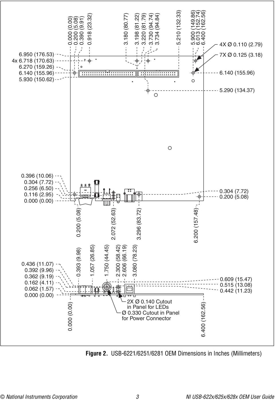
2 Refer to the NI x Specifications document for USB-// specifications, the NI x Specifications document for USB-// specifications, and the NI x Specifications document for USB-/ specifications. Refer to the M Series User Manual for more information about USB-x/x/x devices. You can find all documentation at ni.com/manuals. Dimensions Figure shows the dimensions of the USB-// OEM device. NI USB-x/x/x OEM User Guide ni.com

3 0.000 (0.00) 0.00 (.0) 0.0 (.) 0. (.).0 (0.). (.).0 (.).0 (.). (.).0 (.).00 (.).0 (.).00 (.) X Ø 0.0 (.).0 (.) x. (0.).0 (.).0 (.).0 (0.) X Ø 0. (.).0 (.) 0. (0.0) 0.0 (.) 0. (.0) 0. (.) (0.00) 0.00 (.0).0 (.). (.).00 (.).0 (.) 0.0 (.) 0.00 (.0) 0. (.0) 0. (.) 0. (.) 0. (.) 0.0 (.) (0.00) (0.00) 0. (.).0 (.).0 (.).00 (.).0 (.).00 (.) X Ø 0.0 Cutout in Panel for LEDs Ø 0.0 Cutout in Panel for Power Connector.00 (.) 0.0 (.) 0. (.0) 0. (.) Figure. USB-// OEM Dimensions in Inches (Millimeters) National Instruments Corporation NI USB-x/x/x OEM User Guide
4 Figure shows the dimensions of the USB-//// OEM device..0 (.) x. (0.).0 (.).0 (.).0 (0.). (.). (.) 0. (0.0) 0.0 (.) 0. (.0) 0. (.) (0.00) 0.00 (.0) (0.00) 0.00 (.0) 0.0 (.) 0. (.).0 (.).0 (0.). (.).00 (.). (.).0 (.).0 (.). (.).0 (.).00 (.).0 (.).00 (.) X Ø 0.0 (.) X Ø 0. (.).0 (.).0 (.) 0.0 (.) 0.00 (.0) 0. (.0) 0. (.) 0. (.) 0. (.) 0.0 (.) (0.00) (0.00) 0. (.).0 (.).0 (.).00 (.).0 (.).00 (.) X Ø 0.0 Cutout in Panel for LEDs Ø 0.0 Cutout in Panel for Power Connector.00 (.) 0. (.0) 0.0 (.) 0. (.) Figure. USB-//// OEM Dimensions in Inches (Millimeters) NI USB-x/x/x OEM User Guide ni.com
 NI USB-x/x/x OEM User Guide ni.com")
5 I/O Connector Pinouts Figures through show the connector pinouts for the USB- OEM, USB- OEM, USB- OEM, USB- OEM, USB- OEM, USB- OEM, USB- OEM, and USB- OEM devices. Refer to the M Series User Manual at ni.com/manuals for more information about USB-x/x/x signals and how to connect them. National Instruments Corporation NI USB-x/x/x OEM User Guide

6 0-Pin Digital Connector + V V PFI PFI PFI PFI PFI PFI 0 PFI PFI PFI PFI PFI PFI PFI PFI PFI PFI 0 P0. P0. P0. P0. P0. P0. P0. P0.0 -Pin Analog Connector AI AI AI 0 AI AI AI AI AI AI AI 0 AI 0 AI AI AI AI 0 AI 0 AI SENSE NC AO AO 0 NC = No Connect Figure. USB- OEM Connector Pinout NI USB-x/x/x OEM User Guide ni.com

7 Bank 0-Pin Analog/Digital Connectors Bank + V V PFI PFI PFI PFI PFI PFI 0 PFI PFI PFI PFI PFI PFI PFI PFI PFI PFI 0 P0. P0. P0. P0. P0. P0. P0. P0.0 AI AI AI AI AI AI AI AI AI AI AI AI AI AI AI AI AI AI AI AI AI AI 0 AI AI AI AI AI AI AI AI AI AI 0 AI AI 0 AI AI AI AI AI AI Bank -Pin Analog Connectors Bank AI AI AI AI AI AI 0 AI AI AO AO AI AI AI AI AI AI AI AI 0 AI SENSE NC AI AI AI AI AI AI 0 AI AI AI AI AI AI AI AI AI AI 0 AI AI AI AI 0 AI AI AI AI AI SENSE NC = No Connect Figure. USB- OEM Connector Pinout National Instruments Corporation NI USB-x/x/x OEM User Guide

8 Bank 0-Pin Digital Connectors Bank + V V P0. P0.0 P0. P0. P0. P0. P0. P0. P0. P0. P0. P0.0 P0. P0. P0. P0. P0. P0. P0. P0. P0. P0.0 P0. P0. + V V PFI PFI PFI PFI PFI PFI 0 PFI PFI PFI PFI PFI PFI PFI PFI PFI PFI 0 P0. P0. P0. P0. P0. P0. P0. P0.0 Bank -Pin Analog Connectors Bank AI AI 0 AI AI AI AI AI AI AO AO AI AI AI AI 0 AI AI AI AI AI SENSE NC AI AI AI AI AI AI 0 AI AI AO AO AI AI AI AI AI AI AI AI 0 AI SENSE NC NC = No Connect NC = No Connect Figure. USB- OEM Connector Pinout NI USB-x/x/x OEM User Guide ni.com

9 0-Pin Digital Connector + V V PFI PFI PFI PFI PFI PFI 0 PFI PFI PFI PFI PFI PFI PFI PFI PFI PFI 0 P0. P0. P0. P0. P0. P0. P0. P0.0 -Pin Analog Connector AI AI AI 0 AI AI AI AI AI AI AI 0 AI 0 AI AI AI AI 0 AI 0 AI SENSE APFI 0 AO AO 0 Figure. USB-/ OEM Connector Pinout National Instruments Corporation NI USB-x/x/x OEM User Guide

10 Bank 0-Pin Analog/Digital Connectors Bank + V V PFI PFI PFI PFI PFI PFI 0 PFI PFI PFI PFI PFI PFI PFI PFI PFI PFI 0 P0. P0. P0. P0. P0. P0. P0. P0.0 AI AI AI AI AI AI AI AI AI AI AI AI AI AI AI AI AI AI AI AI AI AI 0 AI AI AI AI AI AI AI AI AI AI 0 AI AI 0 AI AI AI AI AI AI Bank -Pin Analog Connectors Bank AI AI AI AI AI AI 0 AI AI AO AO AI AI AI AI AI AI AI AI 0 AI SENSE APFI 0 AI AI AI AI AI AI 0 AI AI AI AI AI AI AI AI AI AI 0 AI AI AI AI 0 AI AI AI AI AI SENSE Figure. USB- OEM Connector Pinout NI USB-x/x/x OEM User Guide 0 ni.com

11 Bank 0-Pin Digital Connectors Bank + V V P0. P0.0 P0. P0. P0. P0. P0. P0. P0. P0. P0. P0.0 P0. P0. P0. P0. P0. P0. P0. P0. P0. P0.0 P0. P0. + V V PFI PFI PFI PFI PFI PFI 0 PFI PFI PFI PFI PFI PFI PFI PFI PFI PFI 0 P0. P0. P0. P0. P0. P0. P0. P0.0 Bank -Pin Analog Connectors Bank AI AI 0 AI AI AI AI AI AI AO AO AI AI AI AI 0 AI AI AI AI AI SENSE APFI AI AI AI AI AI AI 0 AI AI AO AO AI AI AI AI AI AI AI AI 0 AI SENSE APFI 0 Figure. USB-/ OEM Connector Pinout National Instruments Corporation NI USB-x/x/x OEM User Guide

12 Default Counter/Timer Pinouts By default, NI-DAQmx routes the counter/timer inputs and outputs to the PFI pins, shown in Table. Table. NI-DAQmx Default Counter/Timer Pins Counter/Timer Signal Default Terminal Name CTR 0 SRC PFI CTR 0 GATE PFI CTR 0 AUX PFI 0 CTR 0 OUT PFI CTR 0 A PFI CTR 0 Z PFI CTR 0 B PFI 0 CTR SRC PFI CTR GATE PFI CTR AUX PFI CTR OUT PFI CTR A PFI CTR Z PFI CTR B PFI FREQ OUT PFI NI USB-x/x/x OEM User Guide ni.com

13 Attaching External LEDs USB-x/x/x OEM devices have two LEDs that reflect the device state. The green READY LED indicates when the device is powered on and configured as a USB device. The yellow ACTIVE LED indicates USB bus activity. Three connectors on the device allow you to connect an external LED circuit to the device, as shown in Figure 0. To connect an external READY LED, use E as the positive connection (+. V) and E as the negative connection. To connect an external ACTIVE LED, use E as the positive connection and E as the negative connection. E is current limited with a 00 Ω resistor to the. V internal supply. This configuration limits the current to approximately ma into a single external LED or approximately ma each when both LEDs are lit. You also can limit this current further by using external resistors, also shown in Figure 0. OEM (On-Board) E E E. V 00 Ω E E E External READY LED External ACTIVE LED Figure 0. Schematic for External LED Circuits National Instruments Corporation NI USB-x/x/x OEM User Guide

14 XF Power Switch The power switch on the USB-x/x/x OEM device powers the device on and off. Figure shows the pins on the power switch and circuitry. 00 kω to Ground VDC Out VDC In 00 kω SW Switch NC NC Outer Shell J/J/J Power to Device SW 00 kω XF FUSE J/J/J Power Connector Figure. Schematic for the Power Switch Pin, VDC In, is connected to VDC through the fuse (reference designator XF). The VDC is the voltage provided by the power supply through the power connector (reference designator J/J/J ) and must be 0 VDC, 0 W. Pin, VDC Out, provides power to the circuitry on the device. When the switch is in the On position, the VDC power supply from pin is routed to pin. Pin, 00 kω to Ground, connects pin to ground through a 00 kω resistor when the switch is in the Off position. The power connector is designated as J on USB-/ OEM devices, J on USB-/ OEM devices, and J on USB-/// OEM devices. NI USB-x/x/x OEM User Guide ni.com
 and must be 0 VDC, 0 W. Pin, VDC Out, provides power to the circuitry on the device.")
15 Connecting the USB-x/x/x OEM Device to Your Chassis The USB-x/x/x OEM device includes several plated mounting holes that are designed for customer grounded connections, as shown in Figure. Caution Do not use the holes labeled A in Figure as mounting holes. A A A Mounting Hole Connected to Chassis Ground A Do Not Use These as Mounting Holes Figure. Customer Mounting Holes (USB-//// OEM Shown) Caution (USB-x Devices) Exercise caution when placing USB-x OEM devices inside an enclosure. Auxiliary cooling may be necessary to keep the device under the maximum ambient temperature rating of C, as specified in the NI x Specifications. National Instruments Corporation NI USB-x/x/x OEM User Guide
 Caution (USB-x Devices) Exercise caution when placing USB-x OEM devices inside an enclosure.")
16 Replacing Fuses USB-x/x/x OEM devices have a replaceable T A 0V ( 0 mm) fuse that protects the device from overcurrent through the power connector. (USB-x Devices Only) USB-x OEM devices also have a replaceable F A V fuse that protects the device from overcurrent through the + V terminal(s). Replacement fuse information can be found in Table. To replace a broken fuse in USB-x/x/x OEM devices, complete the following steps.. Power down and unplug the device.. Replace the broken fuse while referring to Figure for the fuse locations. T A 0V ( x 0 mm) Fuse F A V Fuse on USB-x OEM Devices Figure. USB-x/x/x OEM Fuse Locations NI USB-x/x/x OEM User Guide ni.com
 Fuse F A V Fuse on USB-x OEM Devices Figure.")
17 Device Components Table contains information about the components used for interfacing and interacting with the USB-x/x/x OEM device. Table. USB-x/x/x OEM Components Component Reference Designator(s) on PCB Manufacturer LEDs DS Dialight -0 Manufacturer Part Number -pin connectors (USB-// OEM) J M N-00RB (USB-//// OEM) J, J 0-pin connectors (USB-// OEM) P M N0-00UB (USB-//// OEM) P, P USB connector J AMP 0- Power connector (USB-/ OEM) J Switchcraft RA (USB-/ OEM) J (USB-/// OEM) J Power switch SW ITT Industries, Cannon E0JAQE T A 0V fuse XF Littelfuse.00XP F A V fuse (USB-/ OEM) F Littelfuse 000 -pin (USB- OEM) J Honda PCS-ERLMD+ connectors * (USB-// OEM) J, J (USB-/ OEM) J (USB-/ OEM) J, J * Optional mass termination connectors. These are not populated by default. National Instruments Corporation NI USB-x/x/x OEM User Guide
 P M N0-00UB (USB-//// OEM) P, P USB connector J AMP 0- Power connector (USB-/ OEM) J Switchcraft RA (USB-/ OEM) J (USB-/// OEM) J Power switch SW ITT Industries, Cannon E0JAQE")

18 Modifying the USB Device Name in Microsoft Windows Windows Vista/XP Users You can change how the USB-x/x/x OEM device name appears when users install the device in both the Found New Hardware Wizard that appears when the device is initially installed and in the Windows Device Manager. Figure depicts how a USB- OEM device name appears in the Found New Hardware Wizard and Windows Device Manager. Figure. USB- OEM Device in the Found New Hardware Wizard and Device Manager (Windows Vista/XP) To modify the device name in the Found New Hardware Wizard and Windows Device Manager in Microsoft Windows Vista/XP, complete the following steps. Note You must have NI-DAQmx. or later installed on your PC.. Locate the OEMx.inf file in the y:\windows\inf\ directory, where x is the random number assigned to the INF file by Windows, and y:\ is the root directory where Windows is installed. NI USB-x/x/x OEM User Guide ni.com
 To modify the device name in the Found New Hardware Wizard and Windows Device Manager in Microsoft Windows")

19 Note New security updates to Microsoft Vista and NI-DAQ. or later create random INF files for NI hardware. Windows assigns random file numbers to all INF files, which causes the user to search through several INF files until the correct file is located. If you want to revert back, save a copy of this file as OEMx_original.inf in a different location.. Edit the device INF file by opening OEMx.inf with a text editor. At the bottom of this file are the descriptors where Windows looks to identify the device. Locate the two lines of text that contain in quotes the descriptors for the device name you are modifying. Change the descriptor on both lines to the new device name, as shown in Figure. Original File Modified File Figure. INF File Descriptors Changed to My Device (Windows Vista/XP). Save and close the INF file.. Go to the Windows Device Manager. (Windows Vista) In the Device Manager, notice that the OEM device now appears as My Device, as shown in Figure. (Windows XP) In the Device Manager, right-click the OEM device under Data Acquisition Devices, and select Uninstall. Power down the OEM device and disconnect the USB cable from your PC. National Instruments Corporation NI USB-x/x/x OEM User Guide

.")
20 When you reconnect and power on the device, it appears as My Device in the Found New Hardware Wizard and Windows Device Manager, as shown in Figure. Note When the device is initially installed, the Windows alert message may display the following: Found New Hardware: M Series USB xx (OEM). This message appears for a few seconds until the custom name appears and the Found New Hardware Wizard is launched. This alert message device name cannot be changed. Figure. My Device in the Found New Hardware Wizard and Device Manager (Windows Vista/XP) Note Modifying the INF file will not change the USB-x/x/x OEM device name in Measurement & Automation Explorer (MAX). NI USB-x/x/x OEM User Guide 0 ni.com
 Note Modifying the INF file will not change the USB-x/x/x OEM device name in Measurement &")
21 Windows 000 Users Figure depicts how a USB- OEM device name appears in the Found New Hardware Wizard and Windows Device Manager. Figure. USB- OEM Device in the Found New Hardware Wizard and Device Manager (Windows 000) To modify the device name in the Found New Hardware Wizard and Windows Device Manager in Windows 000, complete the following steps. Note You must have NI-DAQmx. or later installed on your PC.. Locate the nimioxsu.inf file in the x:\winnt\inf\ directory, where x:\ is the root directory where Windows is installed. If you want to revert back, save a copy of this file as nimioxsu_original.inf in a different location. National Instruments Corporation NI USB-x/x/x OEM User Guide

22 . Edit the device INF file by opening nimioxsu.inf with a text editor. At the bottom of this file are the descriptors where Windows looks to identify the device. Locate the two lines of text that contain in quotes the descriptors for the device name you are modifying. Change the descriptor on both lines to the new device name, as shown in Figure. Original File Modified File Figure. INF File Descriptors Changed to My Device (Windows 000). Save and close the INF file.. Go to the Windows Device Manager, right-click the OEM device under Data Acquisition Devices, and select Uninstall.. Power down the OEM device and disconnect the USB cable from your PC. NI USB-x/x/x OEM User Guide ni.com
23 When you reconnect and power on the device, it appears as My Device in the Found New Hardware Wizard and Windows Device Manager, as shown in Figure. Note When the device is initially installed, the Windows alert message may display the following: Found New Hardware: M Series USB xx (OEM). This message appears for a few seconds until the custom name appears and the Found New Hardware Wizard is launched. This alert message device name cannot be changed. Figure. My Device in the Found New Hardware Wizard and Device Manager (Windows 000) Note Modifying the INF file will not change the USB-x/x/x OEM device name in Measurement & Automation Explorer (MAX). National Instruments, NI, ni.com, and LabVIEW are trademarks of National Instruments Corporation. Refer to the Terms of Use section on ni.com/legal for more information about National Instruments trademarks. Other product and company names mentioned herein are trademarks or trade names of their respective companies. For patents covering National Instruments products, refer to the appropriate location: Help»Patents in your software, the patents.txt file on your media, or ni.com/patents National Instruments Corporation. All rights reserved. 0E-0 Jun0
NI USB-6008/6009 OEM USER GUIDE
 USER GUIDE NI USB-6008/6009 OEM This document provides information about the dimensions, connectors, and other components of the National Instruments USB-6008/6009 OEM device. For more information about
How To Write A Librao Low Voltage Differential (Lvds) Module On An Nio 6585 Fuserio (Flexrio) Power Supply (Femaleseo) And Power Supply On An Iphone Or Ip
 Module On An Nio 6585 Fuserio (Flexrio) Power Supply (Femaleseo) And Power Supply On An Iphone Or Ip") NI 6585 Specifications This document lists the specifications of the National Instruments 6585 FlexRIO low-voltage differential (LVDS) adapter module. Pair these specifications with your FPGA module specifications.
NI 6585 Specifications This document lists the specifications of the National Instruments 6585 FlexRIO low-voltage differential (LVDS) adapter module. Pair these specifications with your FPGA module specifications.
NI 653x Cable Adapter
 USER GUIDE NI 653x Cable Adapter Contents The NI 653x cable adapter interfaces with National Instruments high-speed digital I/O (DIO) devices. The cable adapter provides an easy way to connect the Very
NI 6601/6602. Contents CALIBRATION PROCEDURE. ni.com/manuals
 CALIBRATION PROCEDURE NI 6601/6602 Français Deutsch ni.com/manuals This document contains information and instructions for calibrating the National Instruments 6601/6602 data acquisition devices. Contents
INSTALLATION INSTRUCTIONS 160-Pin Cable for the NI PXI-2530B
 INSTALLATION INSTRUCTIONS 160-Pin Cable for the NI PXI-2530B Contents This guide describes how to connect and use the National Instruments 160-pin shielded cable for the NI PXI-2530B which has a maximum
Unpack and Install the Devices, Accessories, and Cables
 READ ME FIRST NI-DAQmx and DAQ Device Installation Guide Français Deutsch ni.com/manuals Install your software before installing new hardware. Install Application Software Install NI application software,
FIELDPOINT BUS EXTENDER CABLE
 INSTALLATION GUIDE FIELDPOINT BUS EXTENDER CABLE If you have space constraints, you can use the FieldPoint Bus Extender Cable to mount a FieldPoint bank in two or three rows. Caution You should not use
DAQ Getting Started Guide
 DAQ Getting Started Guide This guide describes how to confirm your NI data acquisition (DAQ) device is operating properly. Install your application and driver software, then your device, using the instructions
NI-DAQ mx Base 3.x. Contents GETTING STARTED GUIDE
 GETTING STARTED GUIDE NI-DAQ mx Base 3.x Contents This guide describes how to install and configure the NI-DAQmx Base 3.x software and a data acquisition (DAQ) device. This guide also describes how to
NI-XNET Hardware and Software
 INSTALLATION GUIDE NI-XNET Hardware and Software This installation guide contains instructions to help you install your National Instruments hardware and software. Complete documentation is in the NI-XNET
NI PXI-8232. Installing Your PXI Board INSTALLATION GUIDE
 INSTALLATION GUIDE NI PXI-8232 Installing Your PXI Board This document explains how to install the Ethernet and NI-488.2 drivers for your NI PXI-8232 (part number 189140x-02L, where x is D or higher).
Set Up Your MXI -Express x1 System
 Set Up Your MXI -Express x1 System Terminology This document explains what is needed to set up various MXI-Express x1 hardware configurations. The products covered by this guide are the NI PCI-8361, NI
Universal Serial Bus (USB) to DH-485 Interface Converter
 to DH-485 Interface Converter") Installation Instructions Universal Serial Bus (USB) to DH-485 Interface Converter Catalog Number 1747-UIC Contents Overview..................................................3 Computer and Operating System
Installation Instructions Universal Serial Bus (USB) to DH-485 Interface Converter Catalog Number 1747-UIC Contents Overview..................................................3 Computer and Operating System
Analog Servo Drive 25A8
 Description Power Range NOTE: This product has been replaced by the AxCent family of servo drives. Please visit our website at www.a-m-c.com or contact us for replacement model information and retrofit
USB-6008/6009. Contents USER GUIDE. This user guide describes how to use the National Instruments USB-6008/6009 data acquisition (DAQ) devices.
 devices.") USER GUIDE USB-6008/6009 Contents This user guide describes how to use the National Instruments USB-6008/6009 data acquisition (DAQ) devices. Introduction... 2 Safety Guidelines... 3 Software... 5 Logging
USER GUIDE USB-6008/6009 Contents This user guide describes how to use the National Instruments USB-6008/6009 data acquisition (DAQ) devices. Introduction... 2 Safety Guidelines... 3 Software... 5 Logging
NI 6034E/6035E/6036E Family Specifications
 NI 6034E/6035E/6036E Family Specifications This document lists the I/O terminal summary and specifications for the devices that make up the NI 6034E/6035E/6036E family of devices. This family includes
Coupling Microsoft Excel with NI Requirements Gateway
 Coupling Microsoft Excel with NI Requirements Gateway Contents Using the Excel Type This document explains how NI Requirements Gateway interfaces with Microsoft Excel. Use this document to familiarize
CompactRIO crio-9052
 OPERATING INSTRUCTIONS CompactRIO crio-9052 CompactRIO StarFabric Interface 1 POWER BACKUP STATUS FPGA V1 C V2 2 C Rx INPUT 9 35 V 17 W MAX 3 Tx NI crio-9052 CompactRIO StarFabric Interface 1 LEDs 2 Power
NI 9475 8-Channel, 60 V, High-Speed, Sourcing Digital Output Module
 OPERATING INSTRUCTIONS AND SPECIFICATIONS NI 9475 8-Channel, 60 V, High-Speed, Sourcing Digital Output Module Français Deutsch ni.com/manuals This document describes how to use the National Instruments
Getting Started with the LabVIEW Mobile Module Version 2009
 Getting Started with the LabVIEW Mobile Module Version 2009 Contents The LabVIEW Mobile Module extends the LabVIEW graphical development environment to Mobile devices so you can create applications that
UniPi technical documentation REV 1.1
 technical documentation REV 1.1 Contents Overview... 2 Description... 3 GPIO port map... 4 Power Requirements... 5 Connecting Raspberry Pi to UniPi... 5 Building blocks... 5 Relays... 5 Digital Inputs...
Berkeley Audio Design Alpha USB
 QUICK USER GUIDE v1.2.2 Berkeley Audio Design Alpha USB The Alpha USB is an asynchronous High Speed USB to digital audio interface designed to provide the highest possible audio quality from computer audio
Set Up Your MXI -Express x4 System
 Set Up Your MXI -Express x4 System Terminology This document explains what you will need to set up various MXI-Express x4 hardware configurations. The products covered by this guide are the NI PCIe-8371/8372
PoNET kbd48cnc. User s manual
 PoNET kbd48cnc User s manual Version: 16/10/2012 SAFETY INFORMATION! This product is intended for integration by the user into a computer numerical control (CNC) machine. It is the user's responsibility
Coupling Microsoft Visio with NI Requirements Gateway
 Coupling Microsoft Visio with NI Requirements Gateway Contents This document explains how NI Requirements Gateway interfaces with Microsoft Visio. Use this document to familiarize yourself with the Visio
CAUTION! THE 7I29 USES VOLTAGE AND POWER LEVELS THAT REPRESENT A HAZARD TO LIFE AND LIMB.
 7I29 MANUAL Rev 1.5 CAUTION! THE 7I29 USES VOLTAGE AND POWER LEVELS THAT REPRESENT A HAZARD TO LIFE AND LIMB. THE 7I29 IS INTENDED FOR USE BY OEMS THAT WILL INTEGRATE IT INTO A SYSTEM WITH INTERLOCKS AND
EMBEDDED ACCESS CONTROL Hardware Installation Guide
 EMBEDDED ACCESS CONTROL Hardware Installation Guide Lenel goentry Hardware Installation Guide, product version 1.00. This guide is item number DOC- ENHW-ENU, revision 1.003, April 2009 Copyright 2009 Lenel
NI USB-5681 RF Power Meter Specifications
 NI USB-568 RF Power Meter Specifications General This document lists specifications for the NI USB-568 RF power meter. Minimum or maximum specifications are warranted under the following conditions: hour
Introduction to Data Acquisition
 Introduction to Data Acquisition Overview This tutorial is part of the National Instruments Measurement Fundamentals series. Each tutorial in this series, will teach you a specific topic of common measurement
Installation Instructions
 Installation Instructions Windows USB driver for Installation If a Diagnostic Interface with USB is connected to a PC with a Windows operating system 98, ME, XP or Vista for the first time, it is necessary
UIM2901-5A MACH3 breakout board
 User Manual UIM2901-5A MACH3 Breakout Board UIM2901-5A MACH3 Breakout Board UIM2901-5A MACH3 breakout board Features General DB25 interface between PC and user device Fully buffered opto-isolated I/O (Input
Using the NI 17xx Smart Camera Direct Drive Lighting Controller
 Using the NI 17xx Smart Camera Direct Drive Lighting Controller Overview The use of proper lighting is often overlooked when designing a machine vision application. More robust and accurate inspections
CALIBRATION PROCEDURE NI 9219. Contents. Software Requirements. ni.com/manuals
 CALIBRATION PROCEDURE NI 9219 Français Deutsch ni.com/manuals Contents This document contains information for calibrating the National Instruments 9219. For more information on calibration, visit ni.com/calibration.
AC 800M. EtherNet/IP DeviceNet Linking Device LD 800DN. Power and productivity for a better world TM SP1134
 AC 800M EtherNet/IP DeviceNet Linking Device LD 800DN SP1134 Power and productivity for a better world TM AC 800M EtherNet/IP DeviceNet Linking Device LD 800DN NOTICE This document contains information
Silvertel. Ag5200. 1 Features. 2 Description. Power-over-Ethernet Plus Module. IEEE802.3at and IEEE802.3af compliant. Maximum 30W output power
 Silvertel V1.1 November 2012 Datasheet Pb 1 Features IEEE802.3at and IEEE802.3af compliant Maximum 30W output power Dual In-Line (DIL) package size 50.6mm (L) x 30mm (W) Overload, short-circuit and thermal
INSTALLATION GUIDE. Card Reader & Controller with KIM Swipe Reader for Solitaire 850 / 950 / 850L Learnlok PK2930
 INSTALLATION GUIDE Card Reader & Controller with KIM Swipe Reader for Solitaire 850 / 950 / 850L Learnlok PK2930 Card Reader and Controller Model 3.5 with KIM Swipe Reader Table of Contents 1. Features..................................
Automation System TROVIS 6400 TROVIS 6493 Compact Controller
 Automation System TROVIS 6400 TROVIS 6493 Compact Controller For panel mounting (front frame 48 x 96 mm/1.89 x 3.78 inch) Application Digital controller to automate industrial and process plants for general
DS9490R/DS9490B USB to 1-Wire/iButton Adapters
 9-488; Rev 6/ FEATURES High-Speed Mbps Universal Serial Bus (USB) Interface Supports Standard and Overdrive -Wire Communication Slew-Rate-Controlled -Wire Timing and Active Pullup for Improved -Wire Network
Getting Started with the LabVIEW Mobile Module
 Getting Started with the LabVIEW Mobile Module Contents The LabVIEW Mobile Module extends the LabVIEW graphical development environment to Mobile devices so you can create applications that run on Windows
Appendix C I/O Hardware Installation
 Appendix C I/O Hardware Installation SIGNAL I/O Support: Overview... C-1 Communication Automation Corp (Dart card)... C-2 Data Translation: Overview... C-9 Data Translation under Windows 98/2000/XP...
SAFEPATH 4 Telephone Zone Controller
 SAFEPATH 4 Telephone Zone Controller SP4-TZC P/N 109921 SP4-TZC-P P/N 105590 Installation, Testing, Operation and Maintenance Manual 273 Branchport Avenue, Long Branch, NJ 07740-6899 Ph: (800) 631-2148
Measurement Studio. Contents RELEASE NOTES
 RELEASE NOTES Measurement Studio Contents These release notes introduce Measurement Studio 2010. Refer to this document for information about new features and functionality, installation requirements,
Configure Inverter output for two utility settings, (1)120V/60Hz, (2)220V/50Hz
120V/60Hz, (2)220V/50Hz") HV Solar Inverter System GUI Overview January 2012 TMS320C2000 Systems Applications Collateral The HV Solar Inverter System GUI provides a simple interface to evaluate some of the functionalities of the
HV Solar Inverter System GUI Overview January 2012 TMS320C2000 Systems Applications Collateral The HV Solar Inverter System GUI provides a simple interface to evaluate some of the functionalities of the
Safety Precautions WARNINGS
 Safety Precautions This guide contains a variety of safety markings related to the safe and correct operation of the USB Data Transfer Cable. Be sure to read this guide and any related manuals carefully
MAX6683 Evaluation System/Evaluation Kit
 19-2343; Rev 1; 3/07 MAX6683 Evaluation System/Evaluation Kit General Description The MAX6683 evaluation system (EV system) consists of a MAX6683 evaluation kit (EV kit) and a companion Maxim CMODUSB board.
Digital input modules
 8 172 TX-I/O Digital input modules TXM1.8D TXM1.16D Two fully compatible versions: TXM1.8D: 8 inputs, each with a three-color LED (green, yellow or red) TXM1.16D: As TXM1.8X, but 16 inputs, each with a
Technical Specifications: The specifications represent a particular hardware platform. Application-specific software is provided.
 Preliminary TECHNICAL DATASHEET #TDAX020700 HYDRAULIC VALVE CONTROLLER 24 I/O 5 Analog and 6 Digital Inputs 1 Temperature Sensor and 1 RPM Sensor Interface 2 PWM Inputs 6 Proportional and 4 ON/OFF Current
Features, Benefits, and Operation
 Features, Benefits, and Operation 2014 Decibel Eleven Contents Introduction... 2 Features... 2 Rear Panel... 3 Connections... 3 Power... 3 MIDI... 3 Pedal Loops... 4 Example Connection Diagrams... 5,6
NI 9423. NI C Series Overview DATASHEET. 8-Channel Sinking Digital Input Module
 DATASHEET NI 9423 8-Channel Sinking Digital Input Module 8-channel, 100 µs digital input 24 V logic, sinking digital input Compatible with NI CompactDAQ counters 250 Vrms, CAT II isolation 10-position
Cable Connection Procedures for Cisco 1900 Series Routers
 CHAPTER 5 Cable Connection Procedures for Cisco 1900 Series Routers This document describes how to connect your Cisco 1941 integrated services router to a power source and to networks and external devices.
Options for ABB drives, converters and inverters. User s manual FDPI-02 diagnostics and panel interface
 Options for ABB drives, converters and inverters User s manual FDPI-02 diagnostics and panel interface Table of contents Table of contents 3 1. FDPI-02 diagnostics and panel interface Safety..............................................
Name Description Model Number. Parameters Min. Typ. Max. Note. Vaux Voltage 9.8 V 12 V 13.2 V Auxiliary Supply Voltage
 Description Supports DALI interface driver Programming Supports 0-10V Programmable Driver Programming Supports Other Controllers (TDD-ANPNx, SDD-AAPNx) Off-line programming capability Auto programming
3.5'' SATA to USB 3.0 & esata External Hard Drive Enclosure U SER S MANUA L
 3.5'' SATA to USB 3.0 & esata External Hard Drive Enclosure U SER S MANUA L Package Contents: 3.5'' SATA to USB 3.0 & esata External Hard Drive Enclosure 1 3.5" HDD Enclosure 2 Power Adapter 3 USB 3.0
S-series Mass Connection Solutions
 DeltaV Distributed Control System Product Data Sheet March 2015 S-series Mass Connection Solutions Fast, easy and error-free cabinet wiring Modular design, improves reliability Lowers overall termination
How To Power A Schen
 Automation / Mini Type SCH32F Hollow Shaft Encoder - Ø 32 mm Hollow Bore: Ø 6 mm to Ø 3/8 inch Resolution up to 5000 ppr IP 65 (IP 50 for IDC connector option) Electrical Specifications Code: Resolution:
Application/Connection Examples
 This Quick Start Guide is designed to familiarize the user with the connection and configuration of the DTS-305 DIN rail mounted single / 3 phase power & energy meter with RS-485 or TCP communications.
Material: Weight: Bearing Life: Shaft Speed: Starting Torque: Mass Moment of Inertia: Shaft Loads:
 Automation / Mini Type SCH32F Hollow Shaft Encoder - Ø 32 mm Hollow Bore: Ø 6 mm to Ø 3/8 inch Resolution up to 5000 ppr IP 65 (IP 50 for IDC connector option) Electrical Specifications Code: Resolution:
USBSPYDER08 Discovery Kit for Freescale MC9RS08KA, MC9S08QD and MC9S08QG Microcontrollers User s Manual
 USBSPYDER08 Discovery Kit for Freescale MC9RS08KA, MC9S08QD and MC9S08QG Microcontrollers User s Manual Copyright 2007 SofTec Microsystems DC01197 We want your feedback! SofTec Microsystems is always on
I STAR COMPUTER CO., LTD
 I STAR COMPUTER CO., LTD Mini Redundant Power Supply 300W+300W for IPC-Computer Model No. TC-300R8 Table of content 1. Introduction...1 2. Specification 2.1 Input Voltage...1 2.2 DC Output...1 2.3 PS-ON
PCI/PXI ETHERNET ADAPTERS
 INSTALLATION GUIDE PCI/PXI ETHERNET ADAPTERS Installing Your PCI Board National Instruments offers several Ethernet adapters based on the Intel 82559-compatible Ethernet controller. This document explains
Transmitter Interface Program
 Transmitter Interface Program Operational Manual Version 3.0.4 1 Overview The transmitter interface software allows you to adjust configuration settings of your Max solid state transmitters. The following
RF Power Amplifier PA10W Owner s Manual SpinCore Technologies, Inc. http://www.spincore.com
 RF Power Amplifier PA10W Owner s Manual SpinCore Technologies, Inc. http://www.spincore.com Congratulations and thank you for choosing a design from SpinCore Technologies, Inc. We appreciate your business!
DOSISYS. Hands Free Reader LDM 210 - LDM 220. User Manual 127356A
 DOSISYS LDM 210 - LDM 220 Hands Free Reader User Manual 127356A Publication, translation and reproduction total or partial of this document is strictly forbidden without authorization MGP Instruments
Whale 3. User Manual and Installation Guide. DC Servo drive. Contents. 1. Safety, policy and warranty. 1.1. Safety notes. 1.2. Policy. 1.3. Warranty.
 Whale 3 DC Servo drive User Manual and Installation Guide Contents 1. Safety, policy and warranty. 1.1. Safety notes. 1.2. Policy. 1.3. Warranty. 2. Electric specifications. 2.1.Operation ranges. 3. Connections
Voltage Regulator SPAU 341 C. Product Guide
 Issued: July 1998 Status: Updated Version: D/25.04.2006 Data subject to change without notice Features Comprehensive voltage regulation for power transformers with on-load tapchangers in distribution substations
USB-Blaster Download Cable User Guide
 USB-Blaster Download Cable User Guide Subscribe UG-USB81204 101 Innovation Drive San Jose, CA 95134 www.altera.com TOC-2 Contents Introduction to USB-Blaster Download Cable...1-1 USB-Blaster Revision...1-1
Mini Breakout-Board. CNC Interface for LPT Port. Installation Manual Version 4
 Mini CNC Interface for LPT Port Version 4 Product Brief This breakout-board is designed to connect up to four stepper or servo drives to the parallel port of a PC. This requires the use of a CNC controller
USB-QUAD08. Eight-channel Quadrature Encoder Input Device. Specifications
 Eight-channel Quadrature Encoder Input Device s Document Revision 1.1 May 2012 Copyright 2012 s All specifications are subject to change without notice. Typical for 25 C unless otherwise specified. s in
Advanced Data Capture and Control Systems
 Advanced Data Capture and Control Systems Tronisoft Limited Email: sales@tronisoft.com Web: www.tronisoft.com RS232 To 3.3V TTL User Guide RS232 to 3.3V TTL Signal Converter Modules P/N: 9651 Document
with Electronic Assistant
 TECHNICAL DATASHEET #TDAX100200 BLDC Motor Drive Drives a 12V, 24V or 48V BLDC motor Bidirectional, up to 25A Smooth speed control using Hall Sensors CAN (SAE J1939) with Electronic Assistant Features:
Multi-Range Programmable DC Power Supplies 9115 Series
 Data Sheet 1200 W Multi-Range DC Power Supplies Features & Benefits Any 9115 series model can replace several supplies on your bench or in your rack. Unlike conventional supplies with fixed output ratings,
HMI display Installation Guide
 HMI display Installation Guide Product Description Specifications Important Information o Package Contents o Related Documents o Accessories Cautions and Warnings Mounting and Dimensions o BAC-DIS-ENC
Product Specification instalert Rapid Messenger Variable Message Sign
 instalert 2 units to cover any application instalert 18 (ia18): 18 x 28 full matrix instalert 24: (ia24): 24 x 60 full matrix Size, Weight without battery ia18: 30 x 20 x 2.74, 29 lbs ia24: Folds to fits
Servo Motors (SensorDAQ only) Evaluation copy. Vernier Digital Control Unit (DCU) LabQuest or LabPro power supply
 Evaluation copy. Vernier Digital Control Unit (DCU) LabQuest or LabPro power supply") Servo Motors (SensorDAQ only) Project 7 Servos are small, relatively inexpensive motors known for their ability to provide a large torque or turning force. They draw current proportional to the mechanical
Servo Motors (SensorDAQ only) Project 7 Servos are small, relatively inexpensive motors known for their ability to provide a large torque or turning force. They draw current proportional to the mechanical
StructureScan HD Module. Installation Guide ENGLISH. www.bandg.com www.simrad-yachting.com www.lowrance.com
 StructureScan HD Module Installation Guide ENGLISH www.bandg.com www.simrad-yachting.com www.lowrance.com Disclaimer As Navico is continuously improving this product, we retain the right to make changes
Portable BACnet /IP to MS/TP Router
 Portable BACnet /IP to MS/TP Router Installation Instructions TL-BRTRP-0 Part No. 24-10414-2, Rev. F Issued April 2016 Refer to the QuickLIT website for the most up-to-date version of this document. Applications
NI Real-Time Hypervisor for Windows
 QUICK START GUIDE NI Real-Time Hypervisor Version 2.1 The NI Real-Time Hypervisor provides a platform you can use to develop and run LabVIEW and LabVIEW Real-Time applications simultaneously on a single
HWg-STE HWg-STE PoE MANUAL
 HWg-STE HWg-STE PoE MANUAL www.hw-group.com Page 2 HWg-STE connectors LED indicators Green: Power & Mode Yellow: Link & Activity SENSORS S1 and S2 ports for connecting temperature or humidity sensors.
DCS Input/Output Relay Card Series
 Input/Output Relay Card Series I/O RELAY CARD (with loopback test function) 8N The 8N series I/O Relay Cards easily and quickly standardize and facilitate installation of the relay board. Loopback test
Advantium 2 Plus Alarm
 ADI 9510-B Advantium 2 Plus Alarm INSTALLATION AND OPERATING INSTRUCTIONS Carefully Read These Instructions Before Operating Carefully Read These Controls Corporation of America 1501 Harpers Road Virginia
543-0032-00, 943-0032-00. User s Manual
 543-0032-00, 943-0032-00 User s Manual 1 Comfort Alert Diagnostics Faster Service And Improved Accuracy The Comfort Alert diagnostics module is a breakthrough innovation for troubleshooting heat pump and
DAQ. NI SCB-68A User Manual. 68-Pin Shielded Connector Block. ni.com/manuals. NI SCB-68A User Manual. August 2012 375865A-01
 DAQ NI SCB-68A User Manual 68-Pin Shielded Connector Block NI SCB-68A User Manual Français Deutsch ni.com/manuals August 2012 375865A-01 Support Worldwide Technical Support and Product Information ni.com
Color Mark Sensor with Red or Green LED E3S-VS
 Color Mark Sensor with Red or Green LED Rugged IP67 Color Mark Sensor 1 ms response time Detects a wide variety of color marks PNP or NPN output ls Light-on/ Dark-on operation, wire selectable Vertical
PCAN-ISA. CAN Interface for ISA. User Manual
 PCAN-ISA CAN Interface for ISA User Manual Products taken into account Product Name Model Item Number PCAN-ISA Single Channel One CAN channel IPEH-002074 PCAN-ISA Dual Channel Two CAN channels IPEH-002075
INSTALLATION INSTRUCTIONS
 LIGHTING CONTROL PANELS 4 AND 8 RELAYS INSTALLATION INSTRUCTIONS INSTALLATION OVERVIEW The installation instructions contained in this document are provided as a guide for proper and reliable installation.
www.sebury.com.cn Digital Keypad Use s Manual
 K3 K4 www.sebury.com.cn Digital Keypad Use s Manual Contents Introduction Introduction Specifications Intramural Interface Circuit 3 Mounting 3 Wiring 5 Power UP 7 Engineer Programming Mode 7 The K3/K4
R60 USB to CAN interface Manual (1.5 EN)
") R60 USB to CAN interface Manual (1.5 EN) General information R60 USB to CAN interface Manual Version 1.5 EN, 02/2010, DOC01586 Copyright 2010 by ; all rights reserved. Eugen-Adolff-Strasse 134, D-71522
R60 USB to CAN interface Manual (1.5 EN) General information R60 USB to CAN interface Manual Version 1.5 EN, 02/2010, DOC01586 Copyright 2010 by ; all rights reserved. Eugen-Adolff-Strasse 134, D-71522
650W Single Output Power Supply 15V 24V. 27V 48V Rated Current. 0 ~ 100A 0 ~ 50A 0 ~ 40A 0 ~ 27A 0 ~ 24A 0 ~ 13.6A Rated Power
 Features: Universal AC input / Full range Programmable output Voltage (0% ~ 05%) Programmable output Current (% ~ 05%) + / 0.5A auxiliary output Forced current sharing at parallel operation Power OK signal
TS510 & TS500. Installation & User Guide. Compatible Equipment
 Installation & User Guide Compatible Equipment TS510 REM - Remote Keypad 9040 - Loudspeaker DC54/58 - Digital Communicator SD1+ - Speech Dialler 496525 Issue A 1 of 10 TS510 and TS500 Overview Introduction
WinLIN Setup and Operation:
 Frequently Asked Questions about the 07551-Series Masterflex L/S Computer-Compatible drives and about the Masterflex WinLIN Linkable Instrument Control Software (07551-70) WinLIN Setup and Operation: Will
Measurement Studio. Contents RELEASE NOTES
 RELEASE NOTES Measurement Studio Contents These release notes introduce Measurement Studio 8.1.2. Refer to this document for installation requirements, deployment requirements, installation instructions,
USB I/O CONTROL BOX 8 relays, 8 digital I/O lines and 8 HV inputs
 USB I/O CONTROL BOX 8 relays, 8 digital I/O lines and 8 HV inputs The Big Deal USB HID device compatible with 32/64 Bit operating systems 8 TTL/LVTTL digital I/O channels, 8 High Voltage digital inputs
McAfee Encrypted USB Hard Disk Non-Bio Quick Start Guide
 McAfee Encrypted USB Hard Disk Non-Bio Quick Start Guide COPYRIGHT Copyright 2010 McAfee, Inc. All Rights Reserved. No part of this publication may be reproduced, transmitted, transcribed, stored in a
TM7BDM8B expansion block - TM7 - IP67-8 DI/DO - 24V DC - 0.5 A - M8 connector
 Product datasheet Characteristics TM7BDM8B expansion block - TM7 - IP67-8 DI/DO - 24V DC - 0.5 A - M8 connector Main Range of product Product or component type Range compatibility Enclosure material Bus
Series LC6D/LC6C. To power supply PLC. LC6C dedicated teaching box P.971. Options P.973
 Series LCD To power supply Electric Actuator Series LCC Stepper Motor Driver LCD Series LX Dedicated Stepper Motor Driver and Positioning Driver Series LCD/LCC PLC Positioning unit (Not incl. To be provided
Wireless Router Setup Manual
 Wireless Router Setup Manual NETGEAR, Inc. 4500 Great America Parkway Santa Clara, CA 95054 USA 208-10082-02 2006-04 2006 by NETGEAR, Inc. All rights reserved. Trademarks NETGEAR is a trademark of Netgear,
WD-AMX Water Detection Controllers
 Page 1 of 5 WD-AMX Water Detection Controllers Features: Benefit: LED Status of leak status VFC output Audible alarm Auto or manual reset alarm output Uses an isolated AC signal which prevents oxidation
Electronic Control Devices The European Product Catalogue 2007
 FX14 Field Controller (1/4) FX14 Field Controller The FX14 is an equipment field controller in the Facility Explorer range of products. The controller is designed specifically for commercial Heating, Ventilating,
ST Series POWER SUPPLIES USER INSTRUCTIONS
 Introduction These instructions detail the installation and operation requirements for the ST20 & ST35 power supplies. These have been designed for operation in RV s providing a DC power system, with optional
1000W Single Output Power Supply 15V 24V. Protection type: Total Power limit, Latch-style (Recovery after reset AC power ON or inhibit)
") 000W Single Output Power Supply AK-000 series Features: Universal AC input / Full range Programmable output Voltage (0% ~ 05%) Programmable output Current (% ~ 05%) + / 0.5A auxiliary output U profile,
000W Single Output Power Supply AK-000 series Features: Universal AC input / Full range Programmable output Voltage (0% ~ 05%) Programmable output Current (% ~ 05%) + / 0.5A auxiliary output U profile,