4. Accessories for Cables. 5. EPC (Eupen Passive Components) 6. Packing Information
|
|
|
- Molly Kelley
- 7 years ago
- Views:
Transcription
1 Edition 11 / 2011

2 2
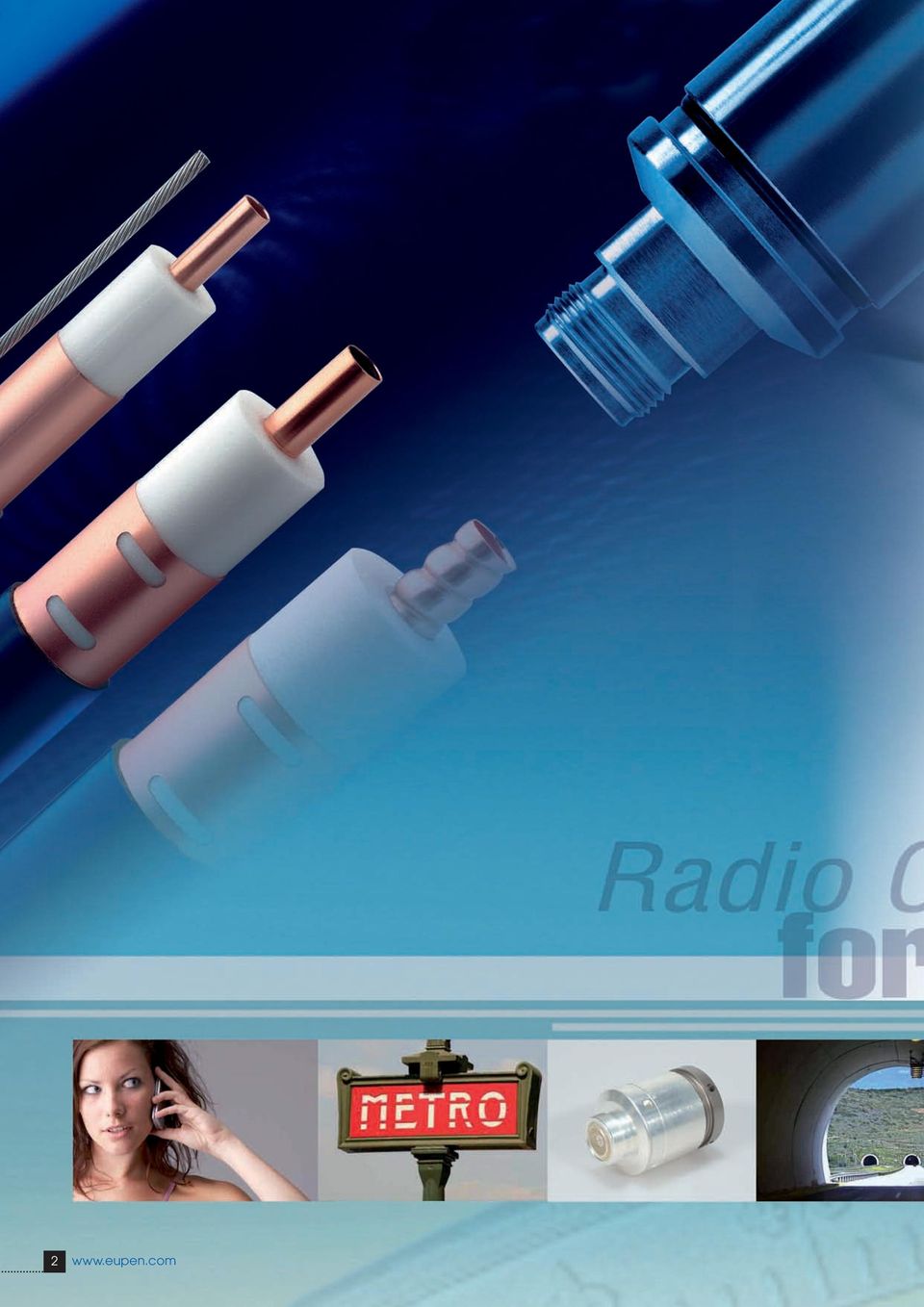
3 1. Introduction 100 Years of Experience Over the World Introduction to Eupen Radiating Cables & Technical Parameters Cable Selection Guide Cables Characteristics LSC LSC LSC RMC RMC 12-A RMC 12-T RMC 12-CL RMC 12-CH RMC RMC 58-T RMC RMC 78-T RMC 78-B RMC 114 A Series RMC 114-T A Series RMC 114-B A Series RMC 158 A Series RMC 158-T A Series RMC 158-B A Series CMC Radiating Cable with Integrated Messenger Wire Accessories for Cables Connectors Cable Preparation Tools Jumper Cables Grounding Kits Additional Weatherproofing Solutions Hook Hangers Clic Clamp Stainless Steel Clamping Solutions EPC (Eupen Passive Components) Dummy Loads DC Isolators Fixed Attenuators Splitters Directional Couplers Packing Information Technical data, designs and specifications presented in this catalogue are not binding and are subject to change without prior notice. 3

4
5

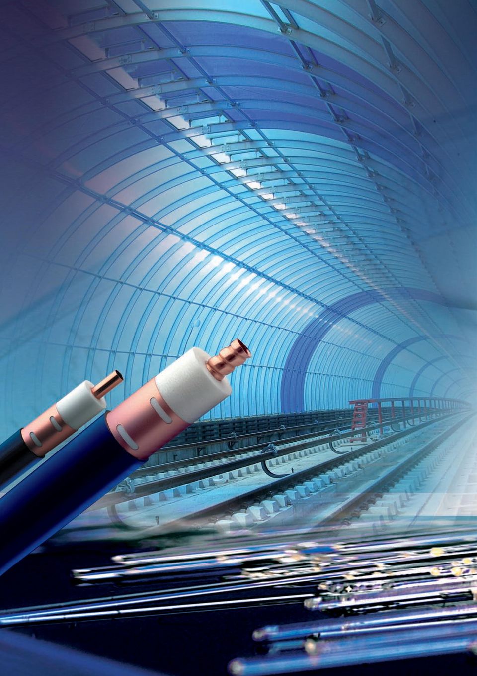
6 Introduction 100 Years of Experience Eupen is a global cable manufacturer offering a wide range of cables and accessories. Our product range includes: Radiating cables Transmission lines Safety cables Power cables Fibre optic cables Instrumentation cables As a leading supplier of transmission lines and accessories to global wireless communications markets, EUPEN has the experience and resources to effectively service customers in today s challenging wireless communications markets. Since broadband transmission became possible, EUPEN has been involved in the design and manufacture of transmission lines. The introduction of Cable Television in 1962 was decisive for the start of coaxial cables on a larger scale. At a time when wireless communication in confined areas, such as underground, street and service tunnels, became an important business to the network operators, EUPEN developed high quality radiating cables. Today, customers worldwide rely upon EUPEN products for wireless transmission of data, voice and video. Underground communication systems using EUPEN radiating cables operate worldwide: in the Metros of Brussels Budapest Caracas Kiev Moscow Paris Santiago de Chili Seoul Washington, DC in road tunnels in Australia Austria Belgium France Germany Greece Norway Singapore Spain the Netherlands and many other challenging locations. 6

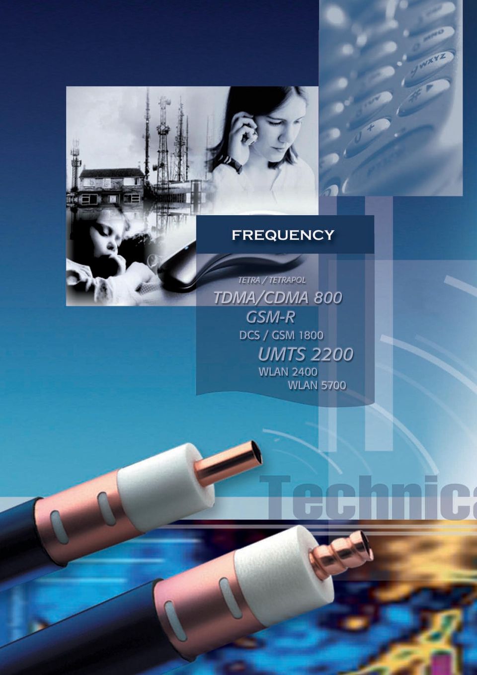
7 Research & Development EUPEN s expertise in the wireless communications market is an invaluable resource to our customers. To anticipate and to follow the continuously changing demand of the market, we carefully evaluate customer feedback, which serves as stimulant for future improvements and developments of EUPEN s product portfolio. Innovative designs, a careful choice of raw materials together with consistent manufacturing and quality assurance techniques, ensure the electrical and mechanical superiority of Eupen cables for the needs of modern radio communication systems such as: TETRA / TETRAPOL TDMA / CDMA 800 GSM 900 DCS / GSM 1800 PCN / PCS 1900 UMTS 2200 W-CDMA 2200 DECT 900 Paging systems GSM-R (European Railway) WLAN 2400 WLAN 5700 EUPEN Support EUPEN provides tailor made support for all kind of RF System needs. To meet customer demand for independent and unbiased support in the expert field of Specialised RF Coverage Solutions, Eupen has gathered a Team of dedicated advisors, who can provide complete support on all aspects of RF Coverage Solutions. Based on the Teams knowledge, that spans more than two decades, combined with good local knowledge of all major market places and by keeping close liaison with Consultants, Manufacturers, System Integrators and Installers world-wide, this Team is able to deliver advice that is combines state of the art technology, latest legislation and cost effectiveness. Together the cables and the connectors from EUPEN are an unbeatable match that optimises the entire system performance: Low attenuation Excellent field strength with low coupling loss Increased amplifier spacing due to very low longitudinal attenuation Simple connector installation Quick cable installation Halogen-free and fire retardant jacketing 7

8 Over the World Agencies Europe Austria Bulgaria Finland Germany Hungary Ireland Italy Norway Poland Romania Russia Spain Slovenia Sweden Tchech Republik Turkey Ukraine Agencies America Canada Mexico USA Florida New Jersey Texas Guatemala Agencies Africa Egypt South Africa 8

9 KABELWERK EUPEN AG Agencies Asia India Iran Pakistan Kingdom of Saudi Arabia Singapore Syria Thailand Taiwan R.O.C. UAE Malmedyer Strasse Eupen BELGIUM EUPEN CABLE MEXICO SA Avenida Manta 705 Lindavista, Mexico, D.F. MEXICO EUPEN CABLE USA Inc th Avenue North Unit D, Clearwater, Florida USA EUPEN CABLES FRANCE Z.A. La Haie Griselle 24, rue du 8 mai Boissy St Leger FRANCE KABELWERK RHENANIA GmbH Agencies Oceania Karl-Kuck-Str Aachen GERMANY Australia New Zealand 9

10 10
11 11

12 Eupen Cables General Radiating cables are used wherever normal radio communication is difficult or impossible, in particular in communication systems where a discrete antenna would not provide adequate coverage, such as in tunnels, underground railways, mines, buildings, etc. RF energy is simultaneously transmitted down radiating cables and radiated from all points along them into the surrounding space. Slots cut into the outer conductor of the coaxial cable allow controlled levels of electromagnetic energy to be radiated both out of and into the cable. A radiating cable functions both as a transmission line and as an antenna. The amount of radiation is quantified by the coupling loss. In the tables of the Data Sheets, the coupling loss is defined as the difference between the power transmitted into the cable and the power received by a λ2-dipole antenna located at a distance of 2 m from the cable. (This definition is taken from IEC ). An Application Note is available, free, on request. Cable construction Radiating cables have generally a coaxial design. They consist of a centre conductor, a dielectric, an outer conductor, which covers the dielectric, and a thermoplastic outer sheath. The characteristic impedance of the cables is normally 50 Ω, but 75 Ω cables are also possible. Sizes from 1/2 up to 1-5/8 are available. The inner conductor is made of solid copper, copperclad aluminium wire, smooth copper tube or corrugated copper tube, according to the conductor size. The dielectric is a cellular polyethylene foam, manufactured by an unique process using an ozone-friendly gas. The low density of the foam guarantees low longitudinal attenuation. The foam dielectric is bonded to the inner conductor by a pre-coating layer. This layer ensures good adhesion of the inner conductor to the dielectric. It also permits easy, clean removal of the dielectric during connector installation. For the outer conductor, a copper tape is used, longitudinally overlapped and bonded to the outer jacket to improve bend radius and water-tightness. 12

13 Halogen-free, Flame-retardant and Fire-resistant features The standard cable construction uses a weather-resistant Halogen-free, Low-smoke and Flame-Retardant (HLFR) outer jacket. This construction meets such international standards as IEC (for flame propagation), IEC (smoke density) and IEC (acidity of evolved gases). If a fire barrier tape (e.g., of mica) is added and placed between dielectric and outer conductor (HLFR/M outer jacket) the cable meets also the requirements of IEC electrical test (circuit integrity). The barrier tape does not affect the transmission characteristics of the cable. Flammability a) Test on flammability of single cables Test in accordance with: IEC EN b) Test on flammability of cable bundles Test in accordance with: Smoke density IEC Cat. C EN Cat. C Test in accordance with: IEC and -2 EN and -2 Corrosive gas emissions Test in accordance with: IEC EN Insulation integrity (HLFR/M jacket only) Test in accordance with: IEC VDE 0472 Part
. If a fire barrier tape (e.g.")
14 Technical Parameters Theory of radiation In a coaxial cable a Transverse Electromagnetical (TEM)- wave travels from the transmitter to the cable end. In the case of a cable with a metallically fully closed outer conductor, the wave inside the cable is totally screened from the surrounding. Outside the coaxial cable, no electromagnetic field, or in other terms no electromagnetic radiation, can be measured. In the same case, no electromagnetic field outside the cable has any influence on the inside wave. By applying apertures to the outer conductor of a coaxial cable, a part of the energy from inside the cable is transferred to the outside surrounding. Also energy can intrude into the cable from the environment. Openings in the outer conductor cause electromagnetic coupling between the field of the inner wave and the outer wave of the outer space of the cable. The arrangement of the openings determines the mechanism of the coupling. The typical example of a radiating cable is a coaxial cable with a braided outer conductor. The largest part of the energy travels as an inside wave through the cable. At any point of inhomogeneity of the outer conductor, surface waves will be induced which travel in both, forward and backward direction along the outside of the cable and interfere with each other. The quality of the radio communication varies very much, due to level variation of the field outside the cable. The installation and the surrounding of the cable affects the radiated field along the cable. Most tunnels contain metallic conductors, such as power cables along the lateral walls, or rails, water pipes, etc. Such conductors can change drastically the electromagnetic field properties. The main electrical characteristics of a radiating cable are: Frequency ranges Longitudinal losses Coupling losses System losses Frequency ranges To determine the right cable for an application, the used frequency ranges has to be known precisely. The design of the apertures in the outer conductor influences the frequency range for which the cable is optimised. Three kinds of radiating coaxial cables are distinguished: CMC (Coupled Mode) Cables: These radiating cables are designed for in-building applications (where the system length is typically less than 100 m), for which a leaky section cable may not be appropriate. LSC (Leaky Section) Cables: Best performances up to 1 GHz. Although this cable can be used at higher frequencies, the sharp increase of its longitudinal losses generally limits its use above 1 GHz. RMC (Radiated Mode) Cables: Designed for a frequency range up to 6 GHz, these cables can be broadband, or are tuned for specific frequency ranges or applications. The particular design of the apertures creates some resonant frequencies. These resonant frequencies are well chosen and do not fall within the currently used communication bands. 14

15 Longitudinal loss The most important characteristic for energy transportation along a cable by the inner wave, is the longitudinal loss (or attenuation loss). A coaxial cable attenuates the signal travelling inside in function of the frequency. The higher the frequency, the higher the attenuation losses. The type of dielectric and the size of the cable mainly influence the longitudinal attenuation. The longitudinal loss depends also on the arrangement of the apertures in the outer conductor. Coupling loss The coupling loss describes the signal loss between the cable and a receiver. It is defined as the ratio of the received power, at a certain distance, to the power in the cable. Because of the reciprocity, analogue considerations are valid for the transmission from an antenna into the cable. The coupling loss is affected by the arrangement of the openings as well as by interferences and reflections of the cable surrounding. System loss The system loss is the sum of longitudinal and coupling loss and of various losses depending on the installation and the environment. Detailed information about the environmental influences are given in the chapter Installation. To design a radio communications systems the system loss needs to be calculated for the uplink and downlink connection. Resonant frequencies The cable design, more precisely the arrangement of the apertures in the outer conductor, can lead to resonant frequencies. This occurs when a certain wavelength interferes with the regular structure of the apertures. The reflection coefficient (SWR) jumps up and the longitudinal loss increases. While LSC and CMC cables don t show this behaviour, RMC cables are designed to present this resonance frequency (stop band) in frequency ranges, where the cables are generally not used. An Application Note is available, free, on request. An intensive radiation means a low coupling loss over a broad frequency range. Two different physical modes carry the energy from the cable into the air : coupling mode and radiating mode. 15

16 Cable Characteristics CMC Cables These radiating cables are designed for in-building applications (where the system length is typically less than 100 m), for which a leaky section cable may not be appropriate. Radiating cables of this type are suited for high-performance applications in the 450 MHz, 900 MHz and 1800 MHz bands. The electromagnetic field diffracted by the apertures of this cable type induces an external mode outside the outer conductor. A current flows on the outer part of the outer conductor and the cable radiates as a long traveling wave antenna. The coupled mode cable is therefore equivalent to a long electrical antenna. The coupled mode corresponds to a power flow, which is parallel to the cable axis. The electromagnetic energy is concentrated in the close vicinity of the cable and decreases quickly with distance: this is the reason why these modes are sometimes referred to as surface waves. The modes, confined around the cable axis, are partially diffracted by surrounding obstacles and discontinuities (clamps, walls,...): a fraction of the power is randomly radiated radially. LSC Cables Leaky sections are pre-punched into the outer conductor; the distance between sections is set to optimise low coupling loss and low longitudinal attenuation over a wide bandwidth. With this unique construction the distance between repeaters can be increased, and the broadband coupling loss is not significantly degraded from that obtained using continuously-slotted coupled-mode cables or radiating-mode cables. LSC cables are mode converters. They consist of a section of leaky cable, inserted in a non-leaky cable. A leaky section is equivalent to a directive antenna connected to the coaxial cable through a power divider. Only a small part of the power propagated inside the cable is extracted and converted into radiation. The spacing between leaky sections has to be chosen in order to provide acceptable results at various frequencies. Cables with leaky sections, designed in this way, can be used under the same conditions as continuous leaky feeders, but with better characteristics for longitudinal and coupling loss. The leaky sections are efficient mode converters and can produce a controlled field level in the cable vicinity, as a function of their length and their electrical characteristics. 16

17 RMC Cables Radiated Mode cables are designed for applications at frequencies of 75 MHz to 6 GHz. The slots are arranged so that the direction of radiation is predominantly orthogonal to the cable axis. This results in optimised, reduced coupling loss variations over specific frequency bands. RMC Cables for Digital Trunk Radio The advent of new Digital Trunk Radio Services, demands improved products to support these techniques. Eupen has met this challenge by including specially designed RMC cables that provide industry leading performances by being optimised for use with this new technology. With a radiated mode cable, the electric field is produced by periodic apertures (slots) on the cable s outer conductor. The aperture spacing d is comparable to the operational wavelength (λ c ). The radiated modes correspond to the in-phase addition of all apertures. They appear for only very well defined slot arrangements and over a well-defined Radiated mode frequency band. The coupling loss is low only in a certain frequency band. Above and below this frequency band it is increased due to interference. The direction of propagation is radially oriented. 17

18 Cable Selection Guide Frequency Bands MHz MHz MHz Applications FM PMR PMR PMR TETRA TETRAPOL page LSC LSC RMC RMC 12-A 30 RMC RMC RMC RMC 158 A Series 60 RMC 12-T 32 RMC 12-CL 34 RMC 12-CH 36 RMC 58-T 40 RMC 78-T 44 RMC 78-B 46 RMC 114-T A Series 50 RMC 114-B A Series 52 RMC 158-T A Series 56 RMC 158-B A Series 58 CMC best good not recommended Jacket Selection Guide Jacket Type IEC /-2 IEC (suffix of Cable Name) Requirements Halogen free Low smoke density non corrosive smoke emission PE HLFR HLFR/M 18
 Requirements Halogen free Low smoke density non corrosive smoke emission PE HLFR HLFR/M 18 www.eupen.")
19 MHz GHz GHz GHz 6 GHz TDMA PCN UMTS ISM WLAN CDMA DECT WLAN GSM 900 GSM 1800 WIFI GSM - R TETRA Important: please always check for resonant frequencies IEC IEC C IEC Flame retardant Fire retardant DC Circuit integrity 19

20

21
22 LSC 12 PRODUCT DESCRIPTION Reference suffix (1) : -HLFR LSC 12-HLFR Fire behaviour Halogen free and flame retardant outer sheath, Low corrosive gas emission acc. to IEC Flame retardant acc. to IEC and IEC cat. C, Low smoke emission acc. to IEC Slots in the copper outer conductor allow a controlled portion of the internal RF energy to be radiated into the surrounding environment. Conversely, a signal transmitted near the cable will couple into the slots and be carried along the cable length. FEATURES and BENEFITS Broadband from 30 MHz to 1.9 GHz Robust Cable, with low bending radius No Resonant Frequencies No Cable Orientation Required Main Applications: Tunnel - FM, TETRA, GSM, GSM-R, DCS-1800 Only for use in Tunnels - Not suitable for use in Buildings TECHNICAL FEATURES Size 1/2 Previous Model Number 512RC8R-HLFR Frequency Range MHz Recommended for Frequency MHz N.A. Cable Type LSC (Leaky Section Cable) Jacket HLFR (Halogen Free Low Smoke Flame Retardant) Slot Design Groups of Slots at longer intervals Impedance Ω 50 +/- 2 Velocity Ratio % 88 Capacitance pf/m 76 Inner Conductor dc Resistance Ω/1000 m (Ω/1000 ft) 1.48 (0.45) HLFR Outer Conductor dc Resistance Ω/1000 m (Ω/1000 ft) 2.62 (0.80) Inner Conductor Material Copper clad aluminium wire (HLFR) Dielectric Material Cellular polyethylene Outer Conductor Material Overlapping copper foil, with slot groups, bonded to the jacket 22
23 LSC 12 TECHNICAL FEATURES (continued) Diameter Inner Conductor mm (in) 4.8 (0.19) Diameter Dielectric mm (in) 12.4 (0.49) Diameter over Jacket mm (in) 15.5 (0.61) Minimum Bending Radius, Single Bend mm (in) 200 (7.87) Cable Weight kg/m (lb/ft) 0.33 (0.22) HLFR Tensile Strength dan (lb) 110 (242) Indication of Slot Alignment N.A. Storage Temperature C ( F) -70 to +85 (-94 to +185) Installation Temperature C ( F) -25 to +60 (-13 to +140) Operation Temperature C ( F) -40 to +85 (-40 to +185) Longitudinal Loss and Coupling Loss (2) Frequency Longitudinal Loss Coupling Loss db/100 m (db/100 ft) C50% [db] C95% [db] 75 MHz 1.87 (0.57) MHz 2.69 (0.82) MHz 3.35 (1.02) MHz 4.93 (1.50) MHz 7.43 (2.26) MHz 11.7 (3.57) MHz 12.2 (3.70) MHz MHz Resonant Frequencies MHz None Clamp Spacing Recommended / Maximum m (ft) 0.5 (1.64) / 1.20 (3.90) Distance to Wall Recommended / Minimum mm (in) ( ) / 50 (1.96) 1) Must be specified in case of order - standard PE jacket available on request. (2) Measured in tunnel according to IEC Ground Level Method. Distance = 2m. C50 & (C95) are the average coupling losses with 50% (95%) probability calculated in accordance with the standard. The above stated values are nominal values and subject to manufacturing tolerances as follows: Longitudinal Loss +/-5 % and Coupling Loss +/- 3dB. As with any radiating cable, the performance in building or tunnel may deviate from figures measured according to the IEC standard. Coupling loss measurements taken in accordance with IEC Free Space Method are available on request These Radiating Cables have been especially developed for use in Tunnels. Due to the Cables inherent design, based on Groups of Slots at longer intervals, these Radiating Cables are not suitable for In-Building use. 23
24 LSC 78 PRODUCT DESCRIPTION Reference suffix (1) : -HLFR LSC 78-HLFR Fire behaviour Halogen free and flame retardant outer sheath, Low corrosive gas emission acc. to IEC Flame retardant acc. to IEC and IEC cat. C, Low smoke emission acc. to IEC Slots in the copper outer conductor allow a controlled portion of the internal RF energy to be radiated into the surrounding environment. Conversely, a signal transmitted near the cable will couple into the slots and be carried along the cable length. FEATURES and BENEFITS Broadband from 30 MHz to 1.9 GHz Robust Cable, with low bending radius No Resonant Frequencies No Cable Orientation Required Main Applications: Tunnel - FM, TETRA, GSM, GSM-R, DCS-1800 Only for use in Tunnels - Not suitable for use in Buildings TECHNICAL FEATURES Size 7/8 Previous Model Number 522RC8R-HLFR Frequency Range MHz Recommended for Frequency MHz N.A. Cable Type LSC (Leaky Section Cable) Jacket HLFR (Halogen Free Low Smoke Flame Retardant) Slot Design Groups of Slots at longer intervals Impedance Ω 50 +/- 2 Velocity Ratio % 88 Capacitance pf/m 76 Inner Conductor dc Resistance Ω/1000 m (Ω/1000 ft) 1.55 (0.47) Outer Conductor dc Resistance Ω/1000 m (Ω/1000 ft) 1.40 (0.43) Inner Conductor Material Smooth copper tube Dielectric Material Cellular polyethylene Outer Conductor Material Overlapping copper foil, with slot groups, bonded to the jacket 24
25 LSC 78 TECHNICAL FEATURES (continued) Diameter Inner Conductor mm (in) 9.2 (0.36) Diameter Dielectric mm (in) 23.5 (0.93) Diameter over Jacket mm (in) 27.0 (1.06) Minimum Bending Radius, Single Bend mm (in) 350 (13.80) Cable Weight kg/m (lb/ft) 0.51 (0.33) HLFR Tensile Strength dan (lb) 140 (309) Indication of Slot Alignment N.A. Storage Temperature C ( F) -70 to +85 (-94 to +185) Installation Temperature C ( F) -25 to +60 (-13 to +140) Operation Temperature C ( F) -40 to +85 (-40 to +185) Longitudinal Loss and Coupling Loss (2) Frequency Longitudinal Loss Coupling Loss db/100 m (db/100 ft) C50% [db] C95% [db] 75 MHz 1.06 (0.32) MHz 1.58 (0.48) MHz 2.01 (0.61) MHz 3.09 (0.94) MHz 4.86 (1.48) MHz (3.08) MHz (3.41) MHz MHz Resonant Frequencies MHz None Clamp Spacing Recommended / Maximum m (ft) 0.5 (1.64) / 1.20 (3.90) Distance to Wall Recommended / Minimum mm (in) ( ) / 50 (1.96) 1) Must be specified in case of order - standard PE jacket available on request. (2) Measured in tunnel according to IEC Ground Level Method. Distance = 2m. C50 & (C95) are the average coupling losses with 50% (95%) probability calculated in accordance with the standard. The above stated values are nominal values and subject to manufacturing tolerances as follows: Longitudinal Loss +/-5 % and Coupling Loss +/- 3dB. As with any radiating cable, the performance in building or tunnel may deviate from figures measured according to the IEC standard. Coupling loss measurements taken in accordance with IEC Free Space Method are available on request These Radiating Cables have been especially developed for use in Tunnels. Due to the Cables inherent design, based on Groups of Slots at longer intervals, these Radiating Cables are not suitable for In-Building use. 25
26 LSC (75 Ohm) PRODUCT DESCRIPTION LSC HLFR Reference suffix (1) : -HLFR Fire behaviour Halogen free and flame retardant outer sheath, Low corrosive gas emission acc. to IEC Flame retardant acc. to IEC and IEC cat. C, Low smoke emission acc. to IEC Slots in the copper outer conductor allow a controlled portion of the internal RF energy to be radiated into the surrounding environment. Conversely, a signal transmitted near the cable will couple into the slots and be carried along the cable length. FEATURES and BENEFITS 75 Ohm impedance Broadband from 30 MHz to 1.9 GHz Robust Cable, with low bending radius No Resonant Frequencies No Cable Orientation Required Main Applications: Tunnel - FM, TETRA, GSM, GSM-R, DCS-1800 Only for use in Tunnels - Not suitable for use in Buildings TECHNICAL FEATURES Size 7/8 Previous Model Number 722RC8R-HLFR Frequency Range MHz Recommended for Frequency MHz N.A. Cable Type LSC (Leaky Section Cable) Jacket HLFR (Halogen Free Low Smoke Flame Retardant) Slot Design Groups of Slots at longer intervals Impedance Ω 75 +/- 2 Velocity Ratio % 88 Capacitance pf/m 50 Inner Conductor dc Resistance Ω/1000 m (Ω/1000 ft) 0.66 (0.20) Outer Conductor dc Resistance Ω/1000 m (Ω/1000 ft) 1.40 (0.43) Inner Conductor Material Copper wire Dielectric Material Cellular polyethylene Outer Conductor Material Overlapping copper foil, with slot groups, bonded to the jacket 26
27 LSC (75 Ohm) TECHNICAL FEATURES (continued) Diameter Inner Conductor mm (in) 5.7 (0.22) Diameter Dielectric mm (in) 23.5 (0.93) Diameter over Jacket mm (in) 27.0 (1.06) Minimum Bending Radius, Single Bend mm (in) 350 (13.8) Cable Weight kg/m (lb/ft) 0.62 (0.42) HLFR Tensile Strength dan (lb) 180 (397) Indication of Slot Alignment N.A. Storage Temperature C ( F) -70 to +85 (-94 to +185) Installation Temperature C ( F) -25 to +60 (-13 to +140) Operation Temperature C ( F) -40 to +85 (-40 to +185) Longitudinal Loss and Coupling Loss (2) Frequency Longitudinal Loss Coupling Loss db/100 m (db/100 ft) C50% [db] C95% [db] 75 MHz 0.86 (0.26) MHz 1.33 (0.41) MHz 1.73 (0.53) MHz 2.82 (0.86) MHz 4.73 (1.44) MHz 9.47 (2.89) MHz (3.17) MHz MHz Resonant Frequencies MHz None Clamp Spacing Recommended / Maximum m (ft) 0.5 (1.64) / 1.20 (3.90) Distance to Wall Recommended / Minimum mm (in) ( ) / 50 (1.96) 1) Must be specified in case of order - standard PE jacket available on request. (2) Measured in tunnel according to IEC Ground Level Method. Distance = 2m. C50 & (C95) are the average coupling losses with 50% (95%) probability calculated in accordance with the standard. The above stated values are nominal values and subject to manufacturing tolerances as follows: Longitudinal Loss +/-5 % and Coupling Loss +/- 3dB. As with any radiating cable, the performance in building or tunnel may deviate from figures measured according to the IEC standard. Coupling loss measurements taken in accordance with IEC Free Space Method are available on request These Radiating Cables have been especially developed for use in Tunnels. Due to the Cables inherent design, based on Groups of Slots at longer intervals, these Radiating Cables are not suitable for In-Building use. 27
28 RMC 12 PRODUCT DESCRIPTION RMC 12-HLFR Reference suffix (1) : -HLFR Fire behaviour Halogen free and flame retardant outer sheath, Low corrosive gas emission acc. to IEC Flame retardant acc. to IEC and IEC cat. C, Low smoke emission acc. to IEC Slots in the copper outer conductor allow a controlled portion of the internal RF energy to be radiated into the surrounding environment. Conversely, a signal transmitted near the cable will couple into the slots and be carried along the cable length. FEATURES and BENEFITS From 30 MHz to 2.5 GHz with resonant frequencies Robust Cable, with low bending radius Main Applications: Tunnel - GSM, GSM-R, DCS-1800, WLAN TECHNICAL FEATURES Size 1/2 Previous Model Number 512RC8RM-HLFR Frequency Range MHz Recommended for Frequency MHz 900 and above Cable Type RMC (Radiated Mode Cable) Jacket HLFR (Halogen Free Low Smoke Flame Retardant) Slot Design Groups of Slots at short intervals Impedance Ω 50 +/- 3 Velocity Ratio % 88 Capacitance pf/m 76 Inner Conductor dc Resistance Ω/1000 m (Ω/1000 ft) 1.48 (0.45) HLFR Outer Conductor dc Resistance Ω/1000 m (Ω/1000 ft) 2.90 (0.88) Inner Conductor Material Copper clad aluminium (HLFR) Dielectric Material Cellular polyethylene Outer Conductor Material Overlapping copper foil, with slot groups, bonded to the jacket 28
29 RMC 12 TECHNICAL FEATURES (continued) Diameter Inner Conductor mm (in) 4.8 (0.19) Diameter Dielectric mm (in) 12.4 (0.49) Diameter over Jacket mm (in) 15.5 (0.61) Minimum Bending Radius, Single Bend mm (in) 200 (7.87) Cable Weight kg/m (lb/ft) 0.23 (0.16) HLFR Tensile Strength dan (lb) 110 (243) Indication of Slot Alignment embossed line 180 opposite Storage Temperature C ( F) -70 to +85 (-94 to +185) Installation Temperature C ( F) -25 to +60 (-13 to +140) Operation Temperature C ( F) -40 to +85 (-40 to +185) Longitudinal Loss and Coupling Loss (2) Frequency Longitudinal Loss Coupling Loss db/100 m (db/100 ft) C50% [db] C95% [db] 75 MHz 2.35 (0.72) MHz 3.25 (0.99) MHz 3.70 (1.13) MHz 5.00 (1.53) MHz 7.70 (2.36) MHz (3.76) MHz (3.90) MHz (4.54) MHz (5.07) Resonant Frequencies MHz 547, 1641, 2734 Clamp Spacing Recommended / Maximum m (ft) 0.5 (1.64) / 1.20 (3.90) Distance to Wall Recommended / Minimum mm (in) ( ) / 50 (1.96) 1) Must be specified in case of order - standard PE jacket available on request. (2) Measured in tunnel according to IEC Ground Level Method. Distance = 2m. C50 & (C95) are the average coupling losses with 50% (95%) probability calculated in accordance with the standard. The above stated values are nominal values and subject to manufacturing tolerances as follows: Longitudinal Loss +/-5 % and Coupling Loss +/- 3dB. As with any radiating cable, the performance in building or tunnel may deviate from figures measured according to the IEC standard. Coupling loss measurements taken in accordance with IEC Free Space Method are available on request 29
30 RMC 12-A PRODUCT DESCRIPTION RMC 12-A-HLFR Reference suffix (1) : -HLFR Fire behaviour Halogen free and flame retardant outer sheath Low corrosive gas emission acc. to IEC Flame retardant acc. to IEC and IEC cat. C Low smoke emission acc. to IEC Slots in the copper outer conductor allow a controlled portion of the internal RF energy to be radiated into the surrounding environment. Conversely, a signal transmitted near the cable will couple into the slots and be carried along the cable length. FEATURES and BENEFITS From 30 MHz to 2.5 GHz with resonant frequencies Robust Cable, with low bending radius Main Applications: AIRCRAFT - GSM, DCS-1800, UMTS, WLAN-short length Specially designed for use in Aircraft TECHNICAL FEATURES Size 1/2 Previous Model Number 512RC8RMA-HLFR Frequency Range MHz Recommended for Frequency MHz 450 and above Cable Type RMC (Radiated Mode Cable) Jacket HLFR (Halogen Free Low Smoke Flame Retardant) Slot Design Groups of Slots at short intervals Impedance Ω 50 +/- 3 Velocity Ratio % 88 Capacitance pf/m 76 Inner Conductor dc Resistance Ω/1000 m (Ω/1000 ft) 1.48 (0.45) Outer Conductor dc Resistance Ω/1000 m (Ω/1000 ft) 3 (0.91) Inner Conductor Material Copper clad aluminium wire Dielectric Material Cellular polyethylene Outer Conductor Material Overlapping copper foil, with slot groups, bonded to the jacket 30
31 RMC 12-A TECHNICAL FEATURES (continued) Diameter Inner Conductor mm (in) 4.8 (0.19) Diameter Dielectric mm (in) 12.4 (0.49) Diameter over Jacket mm (in) 15.5 (0.61) Minimum Bending Radius, Single Bend mm (in) 200 (7.87) Cable Weight kg/m (lb/ft) 0.21 (0.14) HLFR Tensile Strength dan (lb) 110 (242) Indication of Slot Alignment embossed line 180 opposite Storage Temperature C ( F) -70 to +85 (-94 to +185) Installation Temperature C ( F) -25 to +60 (-13 to +140) Operation Temperature C ( F) -40 to +85 (-40 to +185) Longitudinal Loss and Coupling Loss (2) Frequency Longitudinal Loss Coupling Loss db/100 m (db/100 ft) C50% [db] C95% [db] 75 MHz 3.59 (1.09) MHz 4.26 (1.30) MHz 4.67 (1.42) MHz 5.85 (1.78) MHz 9.52 (2.90) MHz 20.8 (6.34) MHz 22.7 (6.92) MHz 30.4 (9.27) MHz 37.8 (11.52) Resonant Frequencies MHz 184, 552, 920 ±5, 1288, 1656, 2024, 2392 Clamp Spacing Recommended / Maximum m (ft) 0.5 (1.64) / 1.20 (3.90) Distance to Wall Recommended / Minimum mm (in) ( ) / 50 (1.96) 1) Must be specified in case of order - standard PE jacket available on request. (2) Measured in tunnel according to IEC Ground Level Method. Distance = 2m. C50 & (C95) are the average coupling losses with 50% (95%) probability calculated in accordance with the standard. The above stated values are nominal values and subject to manufacturing tolerances as follows: Longitudinal Loss +/-5 % and Coupling Loss +/- 3dB. As with any radiating cable, the performance in building or tunnel may deviate from figures measured according to the IEC standard. Coupling loss measurements taken in accordance with IEC Free Space Method are available on request 31
32 RMC 12-T PRODUCT DESCRIPTION RMC 12-T-HLFR Reference suffix (1) : -HLFR Fire behaviour Halogen free and flame retardant outer sheath, Low corrosive gas emission acc. to IEC Flame retardant acc. to IEC and IEC cat. C, Low smoke emission acc. to IEC Slots in the copper outer conductor allow a controlled portion of the internal RF energy to be radiated into the surrounding environment. Conversely, a signal transmitted near the cable will couple into the slots and be carried along the cable length. FEATURES and BENEFITS From 30 MHz to 1 GHz with resonant frequencies Robust Cable, with low bending radius Main Applications: Tunnel - FM, TETRA TECHNICAL FEATURES Size 1/2 Previous Model Number 512RC8RMT-HLFR Frequency Range MHz Recommended for Frequency MHz 450 Cable Type RMC (Radiated Mode Cable) Jacket HLFR (Halogen Free Low Smoke Flame Retardant) Slot Design Groups of Slots at short intervals Impedance Ω 50 +/- 3 Velocity Ratio % 88 Capacitance pf/m 76 Inner Conductor dc Resistance Ω/1000 m (Ω/1000 ft) 1.48 (0.45) HLFR Outer Conductor dc Resistance Ω/1000 m (Ω/1000 ft) 2.80 (0.85) Inner Conductor Material Copper clad aluminium (HLFR) Dielectric Material Cellular polyethylene Outer Conductor Material Overlapping copper foil, with slot groups, bonded to the jacket 32
33 RMC 12-T TECHNICAL FEATURES (continued) Diameter Inner Conductor mm (in) 4.8 (0.19) Diameter Dielectric mm (in) 12.4 (0.49) Diameter over Jacket mm (in) 15.5 (0.61) Minimum Bending Radius, Single Bend mm (in) 200 (7.87) Cable Weight kg/m (lb/ft) 0.22 (0.15) HLFR Tensile Strength dan (lb) 110 (243) Indication of Slot Alignment embossed line 180 opposite Storage Temperature C ( F) -70 to +85 (-94 to +185) Installation Temperature C ( F) -25 to +60 (-13 to +140) Operation Temperature C ( F) -40 to +85 (-40 to +185) Longitudinal Loss and Coupling Loss (2) Frequency Longitudinal Loss Coupling Loss db/100 m (db/100 ft) C50% [db] C95% [db] 75 MHz 2.2 (0.67) MHz 3.0 (0.91) MHz 3.8 (1.16) MHz 5.4 (1.65) MHz 5.9 (1.80) MHz 10.6 (3.23) MHz MHz MHz MHz Resonant Frequencies MHz 37, 111, 185, 259, 334, 408, 482, 556, 630, 704, 778, 853, 927, 1001 Clamp Spacing Recommended / Maximum m (ft) 0.5 (1.64) / 1.20 (3.90) Distance to Wall Recommended / Minimum mm (in) ( ) / 50 (1.96) 1) Must be specified in case of order - standard PE jacket available on request. (2) Measured in tunnel according to IEC Ground Level Method. Distance = 2m. C50 & (C95) are the average coupling losses with 50% (95%) probability calculated in accordance with the standard. All Values are going to be confirmed by independent Test Centre soonest. The above stated values are nominal values and subject to manufacturing tolerances as follows: Longitudinal Loss +/-5 % and Coupling Loss +/- 3dB. As with any radiating cable, the performance in building or tunnel may deviate from figures measured according to the IEC standard. Coupling loss measurements taken in accordance with IEC Free Space Method are available on request 33
34 RMC 12-CL PRODUCT DESCRIPTION RMC 12-CL-HLFR Reference suffix (1) : -HLFR Fire behaviour Halogen free and flame retardant outer sheath Low corrosive gas emission acc. to IEC Flame retardant acc. to IEC and IEC cat. C Low smoke emission acc. to IEC Slots in the copper outer conductor allow a controlled portion of the internal RF energy to be radiated into the surrounding environment. Conversely, a signal transmitted near the cable will couple into the slots and be carried along the cable length. FEATURES and BENEFITS Low Fading at short Aerial to Cable distance Robust Cable Main Applications: WLAN controlled Transportation Systems Optimised for WLAN applications in the GHz band TECHNICAL FEATURES Size 1/2 Previous Model Number N.A. Frequency Range MHz Recommended for Frequency MHz Cable Type RMC (Radiated Mode Cable) Jacket HLFR (Halogen Free Low Smoke Flame Retardant) Slot Design Groups of Slots at short intervals Impedance Ω 50 +/- 3 Velocity Ratio % 88 Capacitance pf/m 76 Inner Conductor dc Resistance Ω/1000 m (Ω/1000 ft) 1.48 (0.45) Outer Conductor dc Resistance Ω/1000 m (Ω/1000 ft) 2.8 (0.85) Inner Conductor Material Copper clad aluminium wire Dielectric Material Cellular polyethylene Outer Conductor Material Overlapping copper foil, with slot groups, bonded to the jacket 34
35 RMC 12-CL TECHNICAL FEATURES (continued) Diameter Inner Conductor mm (in) 4.8 (0.19) Diameter Dielectric mm (in) 12.4 (0.49) Diameter over Jacket mm (in) 15.5 (0.61) Minimum Bending Radius, Single Bend mm (in) 200 (7.87) Cable Weight kg/m (lb/ft) 0.23 (0.16) HLFR Tensile Strength dan (lb) 110 (243) Indication of Slot Alignment embossed line 180 opposite Storage Temperature C ( F) -70 to +85 (-94 to +185) Installation Temperature C ( F) -25 to +60 (-13 to +140) Operation Temperature C ( F) -40 to +85 (-40 to +185) Longitudinal Loss and Coupling Loss (2) Frequency Longitudinal Loss Coupling Loss db/100 m (db/100 ft) C50% [db] C95% [db] 75 MHz 1.87 (0.57) MHz 2.75 (0.83) MHz 3.42 (1.04) MHz 4.96 (1.51) MHz 7.32 (2.22) MHz (3.63) MHz (3.78) MHz (4.22) MHz (4.47) Resonant Frequencies MHz 156, 469, 781, 1094, 1406, 1718, 2031, 2344, 2656 Clamp Spacing Recommended / Maximum m (ft) 0.5 (1.64) / 1.20 (3.90) Distance to Wall Recommended / Minimum mm (in) ( ) / 50 (1.96) 1) Must be specified in case of order - standard PE jacket available on request. (2) Measured in tunnel according to IEC Ground Level Method. Distance = 2m. C50 & (C95) are the average coupling losses with 50% (95%) probability calculated in accordance with the standard. The above stated values are nominal values and subject to manufacturing tolerances as follows: Longitudinal Loss +/-5 % and Coupling Loss +/- 3dB. As with any radiating cable, the performance in building or tunnel may deviate from figures measured according to the IEC standard. Coupling loss measurements taken in accordance with IEC Free Space Method are available on request 35
36 RMC 12-CH PRODUCT DESCRIPTION RMC 12-CH-HLFR Reference suffix (1) : -HLFR Fire behaviour Halogen free and flame retardant outer sheath Low corrosive gas emission acc. to IEC Flame retardant acc. to IEC and IEC cat. C Low smoke emission acc. to IEC Slots in the copper outer conductor allow a controlled portion of the internal RF energy to be radiated into the surrounding environment. Conversely, a signal transmitted near the cable will couple into the slots and be carried along the cable length. FEATURES and BENEFITS Low Fading at short Aerial to Cable distance Robust Cable Main Applications: WLAN controlled Transportation Systems Optimised for WLAN applications in the and GHz bands TECHNICAL FEATURES Size 1/2 Previous Model Number N.A. Frequency Range MHz Recommended for Frequency MHz and Cable Type RMC (Radiated Mode Cable) Jacket HLFR (Halogen Free Low Smoke Flame Retardant) Slot Design Groups of Slots at short intervals Impedance Ω 50 +/- 3 Velocity Ratio % 88 Capacitance pf/m 76 Inner Conductor dc Resistance Ω/1000 m (Ω/1000 ft) 1.48 (0.45) Outer Conductor dc Resistance Ω/1000 m (Ω/1000 ft) 2.8 (0.85) Inner Conductor Material Copper clad aluminium wire Dielectric Material Cellular polyethylene Outer Conductor Material Overlapping copper foil, with slot groups, bonded to the jacket 36
37 RMC 12-CH TECHNICAL FEATURES (continued) Diameter Inner Conductor mm (in) 4.8 (0.19) Diameter Dielectric mm (in) 12.4 (0.49) Diameter over Jacket mm (in) 15.5 (0.61) Minimum Bending Radius, Single Bend mm (in) 200 (7.87) Cable Weight kg/m (lb/ft) 0.23 (0.16) HLFR Tensile Strength dan (lb) 110 (243) Indication of Slot Alignment embossed line 180 opposite Storage Temperature C ( F) -70 to +85 (-94 to +185) Installation Temperature C ( F) -25 to +60 (-13 to +140) Operation Temperature C ( F) -40 to +85 (-40 to +185) Longitudinal Loss and Coupling Loss (2) Frequency Longitudinal Loss Coupling Loss db/100 m (db/100 ft) C50% [db] C95% [db] 5200 MHz 19.1 (5,82) MHz 20.0 (6,10) MHz 21.5 (6,55) Resonant Frequencies MHz 415, 1246, 2077, 2907, 3738, 4568, 5399, 6230 Clamp Spacing Recommended / Maximum m (ft) 0.5 (1.64) / 1.20 (3.90) Distance to Wall Recommended / Minimum mm (in) ( ) / 50 (1.96) 1) Must be specified in case of order - standard PE jacket available on request. (2) Measured in tunnel according to IEC Ground Level Method. Distance = 2m. C50 & (C95) are the average coupling losses with 50% (95%) probability calculated in accordance with the standard. The above stated values are nominal values and subject to manufacturing tolerances as follows: Longitudinal Loss +/-5 % and Coupling Loss +/- 3dB. As with any radiating cable, the performance in building or tunnel may deviate from figures measured according to the IEC standard. Coupling loss measurements taken in accordance with IEC Free Space Method are available on request 37
38 RMC 58 PRODUCT DESCRIPTION RMC 58-HLFR Reference suffix (1) : -HLFR Fire behaviour Halogen free and flame retardant outer sheath, Low corrosive gas emission acc. to IEC Flame retardant acc. to IEC and IEC cat. C, Low smoke emission acc. to IEC Slots in the copper outer conductor allow a controlled portion of the internal RF energy to be radiated into the surrounding environment. Conversely, a signal transmitted near the cable will couple into the slots and be carried along the cable length. FEATURES and BENEFITS Broadband from 30 MHz to 1.9 GHz Robust Cable, with low bending radius Main Applications: Tunnel - GSM, GSM-R, DCS-1800 TECHNICAL FEATURES Size 5/8 Previous Model Number 517RC8RM-HLFR Frequency Range MHz Recommended for Frequency MHz 900 and 1800 Cable Type RMC (Radiated Mode Cable) Jacket HLFR (Halogen Free Low Smoke Flame Retardant) Slot Design Groups of Slots at short intervals Impedance Ω 50 +/- 2 Velocity Ratio % 88 Capacitance pf/m 76 Inner Conductor dc Resistance Ω/1000 m (Ω/1000 ft) 1.9 (0.58) Outer Conductor dc Resistance Ω/1000 m (Ω/1000 ft) 2.04 (0.62) Inner Conductor Material Smooth copper tube Dielectric Material Cellular polyethylene Outer Conductor Material Overlapping copper foil, with slot groups, bonded to the jacket 38
39 RMC 58 TECHNICAL FEATURES (continued) Diameter Inner Conductor mm (in) 6.8 (0.27) Diameter Dielectric mm (in) 17.6 (0.69) Diameter over Jacket mm (in) 21.0 (0.83) Minimum Bending Radius, Single Bend mm (in) 300 (11.8) Cable Weight kg/m (lb/ft) 0.38 (0.25) HLFR Tensile Strength dan (lb) 90 (198) Indication of Slot Alignment embossed line 180 opposite Storage Temperature C ( F) -70 to +85 (-94 to +185) Installation Temperature C ( F) -25 to +60 (-13 to +140) Operation Temperature C ( F) -40 to +85 (-40 to +185) Longitudinal Loss and Coupling Loss (2) Frequency Longitudinal Loss Coupling Loss db/100 m (db/100 ft) C50% [db] C95% [db] 75 MHz 1.36 (0.41) MHz 1.99 (0.61) MHz 2.48 (0.76) MHz 3.58 (1.09) MHz 5.26 (1.60) MHz 9.09 (2.77) MHz 9.55 (2.91) MHz 2400 MHz Resonant Frequencies MHz 119, 358, 597, 835, 1074, 1313, 1551, 1790 ±5 Clamp Spacing Recommended / Maximum m (ft) 0.5 (1.64) / 1.20 (3.90) Distance to Wall Recommended / Minimum mm (in) ( ) / 50 (1.96) 1) Must be specified in case of order - standard PE jacket available on request. (2) Measured in tunnel according to IEC Ground Level Method. Distance = 2m. C50 & (C95) are the average coupling losses with 50% (95%) probability calculated in accordance with the standard. The above stated values are nominal values and subject to manufacturing tolerances as follows: Longitudinal Loss +/-5 % and Coupling Loss +/- 3dB. As with any radiating cable, the performance in building or tunnel may deviate from figures measured according to the IEC standard. Coupling loss measurements taken in accordance with IEC Free Space Method are available on request 39
40 RMC 58-T PRODUCT DESCRIPTION RMC 58-T-HLFR Reference suffix (1) : -HLFR Fire behaviour Halogen free and flame retardant outer sheath, Low corrosive gas emission acc. to IEC Flame retardant acc. to IEC and IEC cat. C, Low smoke emission acc. to IEC Optional: circuit integrity under fire conditions acc. to IEC Flame temperature = 750 C / voltage = 150 V / flame application = 180 min. Slots in the copper outer conductor allow a controlled portion of the internal RF energy to be radiated into the surrounding environment. Conversely, a signal transmitted near the cable will couple into the slots and be carried along the cable length. FEATURES and BENEFITS Broadband from 30 MHz to 1 GHz with resonant frequencies Robust Cable, with low bending radius Main Applications: Tunnel - FM, TETRA TECHNICAL FEATURES Size 5/8 Previous Model Number 517RC8RMT-HLFR / 517MRC8RMT-HLFR (with Mica) Frequency Range MHz Recommended for Frequency MHz 450 Cable Type RMC (Radiated Mode Cable) Jacket HLFR (Halogen Free Low Smoke Flame Retardant) Slot Design Groups of Slots at short intervals Impedance Ω 50 +/- 2 Velocity Ratio % 88 Capacitance pf/m 76 Inner Conductor dc Resistance Ω/1000 m (Ω/1000 ft) 0.70 (0.21) Outer Conductor dc Resistance Ω/1000 m (Ω/1000 ft) 2.18 (0.66) Inner Conductor Material Copper clad aluminium wire / copper tube Dielectric Material Cellular polyethylene Outer Conductor Material Overlapping copper foil, with slot groups, bonded to the jacket 40
41 RMC 58-T TECHNICAL FEATURES (continued) Diameter Inner Conductor mm (in) 6.8 (0.27) Diameter Dielectric mm (in) 17.6 (0.69) Diameter over Jacket mm (in) 21.0 (0.83) Minimum Bending Radius, Single Bend mm (in) 300 (11.8) Cable Weight kg/m (lb/ft) 0.38 (0.25) HLFR Tensile Strength dan (lb) 150 (331) Indication of Slot Alignment embossed line 180 opposite Storage Temperature C ( F) -70 to +85 (-94 to +185) Installation Temperature C ( F) -25 to +60 (-13 to +140) Operation Temperature C ( F) -40 to +85 (-40 to +185) Longitudinal Loss and Coupling Loss (2) Frequency Longitudinal Loss Coupling Loss db/100 m (db/100 ft) C50% [db] C95% [db] 75 MHz 1.7 (0.52) MHz 2.5 (0.76) MHz 3.1 (0.94) MHz 4.2 (1.28) MHz 4.6 (1.40) MHz 10.5 (3.20) MHz MHz MHz MHz Resonant Frequencies MHz 37, 111, 184, 258, 332, 405 ±3, 479, 553, 627, 700, 774, 848, 922, 995 ±5 Clamp Spacing Recommended / Maximum m (ft) 0.5 (1.64) / 1.20 (3.90) Distance to Wall Recommended / Minimum mm (in) ( ) / 50 (1.96) 1) Must be specified in case of order - standard PE jacket available on request. (2) Measured in tunnel according to IEC Ground Level Method. Distance = 2m. C50 & (C95) are the average coupling losses with 50% (95%) probability calculated in accordance with the standard. The above stated values are nominal values and subject to manufacturing tolerances as follows: Longitudinal Loss +/-5 % and Coupling Loss +/- 3dB. As with any radiating cable, the performance in building or tunnel may deviate from figures measured according to the IEC standard. Coupling loss measurements taken in accordance with IEC Free Space Method are available on request 41
The Quality Connection. Cable Solutions for Mobile Networks Business Unit Telecom
 The Quality Connection Cable Solutions for Mobile Networks Business Unit Telecom Connection Technology for Wireless Communication Systems A consistent focus on the market, in-depth sector and product knowledge,
CABLES CABLES. Application note. Link Budget
 CABLES CABLES radiating Link Budget 3. 1. LINK BUDGET The basic elements to calculate a link budget can be illustrated by considering the example shown in Figure 4. It involves a GSM 900 radio coverage
COAX Cables Radio Frequency Cables
 COAX Cables Radio Frequency Cables Contents Page Table of contents Pictographs General information Introduction Types and abbreviations Temparature range Construction Characteristics Special constructions
Coaxial Cables for Medium-Frequency Applications
 Coaxial Cables for Medium-Frequency Applications Coaxial Cables for Medium-Frequency Applications Introduction Telecommunications technology is moving forward rapidly and the need for fast and reliable
Commercial Coaxial Cable
 Commercial Coaxial Cable For the Best in COMMERCIAL TV Reception Solutions! Do you require a Digital TV reception system for your next project? Matchmaster can supply For The Best Design and supply of
Uniprise Solutions COAX 101. White Paper. www.commscope.com
 Uniprise Solutions COAX 101 White Paper www.commscope.com Structured cable systems have very thorough standards for fiber optic and twisted pair installations. The cabling components and installed systems
Communication, Signal & Data Cables
 Communication, Signal & Data Cables Used for indoor installation and interconnection of transmission, telephone, telegraph and electronic equipment as well as media equipments www.alfanar.com Communication
Trunk Cables. www.teletronik.com
 Trunk Cables www.teletronik.com Brief Introduction Teletronik TC series coaxial cable was developed to meet the increasing demand of tomorrow's broadband networks. TC series cable has the highest reliability
TFC/U-JIN Coaxial Cable Product Information Sheet Type: TU6T60-JVB
 Type: TU6T60-JVB Dielectric 2nd Outer (w/optional Floodant) Series 6 Coaxial Cable Copper Clad Steel Foamed Polyethylene Dielectric Bonded AP Laminate Shield 60% Aluminum Braid "Life Time" compound AP
coaxial cable coaxial Cable CERTIFIED 100% certified coaxial cable A cable that is marked Televés, no doubt is a certified cable
 COAXIAL CABLE coaxial Cable 100% certified coaxial cable coaxial cable CERTIFIED The step ahead undertaken by Televés to improve its service and technical excellence, is now reflected in this new challenge.
75 Ω Transmission System
 NRAO NTC-DSL Laboratory Report Dynamic Spectroscopy Laboratory Report Series Report 03 September, 2006 75 Ω Transmission System Chaitali R. Parashare Department of Electrical and Computer Engineering,
Siemens Energy & Automation. structured. WIRING Product Training Series: Advanced Video Session 3
 s structured WIRING Product Training Series: Advanced Video Session 3 1 Table of Contents This presentation will give you a closer look at Video in Structured Wiring applications. The following Areas will
INTERNATIONAL STANDARD
 INTERNATIONAL STANDARD IEC 61156-5 First edition 2002-03 Multicore and symmetrical pair/quad cables for digital communications Part 5: Symmetrical pair/quad cables with transmission characteristics up
CAVEL VS80205 MADE IN ITALY 1000 V
 0,05 9,00 x 7,20 (Pet) (LSZH) Attached CE01 CE02 Sheath Colour black black red Non-migrating Polyester tape longitudinally overlapped (Pet) 25 x 23 µm Outer sheath of Thermoplastic material - black - halogen-free,
Technical Note. Radiating Cable (RCL/RCH) Performance Test & Design Guidlines. Document Code: TN02-RadiatingCable-14 Date: March 6, 2014
 Performance Test & Design Guidlines. Document Code: TN02-RadiatingCable-14 Date: March 6, 2014") Radiating Cable (RCL/RCH) Performance Test & Design Guidlines Document Code: Date: March 6, 2014 Document Information Author Stuart Siegel Description Performance Test & Design Guidelines Date March 6,
Radiating Cable (RCL/RCH) Performance Test & Design Guidlines Document Code: Date: March 6, 2014 Document Information Author Stuart Siegel Description Performance Test & Design Guidelines Date March 6,
Shielding Effectiveness Test Method. Harbour s LL, SB, and SS Coaxial Cables. Designs for Improved Shielding Effectiveness
 Shielding Effectiveness Test Method Harbour s LL, SB, and SS Coaxial Cables Designs for Improved Shielding Effectiveness Harbour Industries 4744 Shelburne Road Shelburne Vermont 05482 USA 802-985-3311
Franz Hirtenfelder and Stephen Murray, CST Computer Simulation Technology and W. L. Gore and Associates (Gore) March 5, 2015
 March 5, 2015") 1 of 7 3/17/2015 9:38 AM Home Franz Hirtenfelder and Stephen Murray, CST Computer Simulation Technology and W. L. Gore and Associates (Gore) March 5, 2015 Editor s Note: A cable that leaks electromagnetic
1 of 7 3/17/2015 9:38 AM Home Franz Hirtenfelder and Stephen Murray, CST Computer Simulation Technology and W. L. Gore and Associates (Gore) March 5, 2015 Editor s Note: A cable that leaks electromagnetic
OPTICAL FIBER CABLES
 OPTICAL FIBER CABLES CONTENTS INTRODUCTION QUALITY ASSURANCE RECOMMENDED ORDERING PARAMETERS GENERALITIES :. Advantage. General Description.. Construction.. Principle TYPICAL SPECIFICATIONS OF OPTICAL
CABLES FOR PHOTOVOLTAIC SOLAR ENERGY INSTALLATIONS FOR CLEAN ENERGY
 CABLES FOR PHOTOVOLTAIC SOLAR ENERGY INSTALLATIONS FOR CLEAN ENERGY One Company Connecting The World POWERFUL PRESENCE PRODUCTS PERFORMANCE PEOPLE General Cable has been a wire and cable innovator for
RADOX railway cables acc. to EN 50264 and EN 50306. Edition 2009
 RADO railway cables acc. to EN 50264 and EN 50306 Edition 2009 Bridging our know how Interdisciplinary knowledge The HUBER+SUHNER Group is a leading international manufacturer of electrical and optical
International Electrotechnical Commission Standards
 International Electrotechnical Commission Standards Standard IEC 60028 IEC 60038 IEC 60050-461 IEC 60055-1 IEC 60055-2 IEC 60092-101 IEC 60092-350 IEC 60092-351 IEC 60092-352 IEC 60092-353 IEC 60092-354
RF & Microwave cable assemblies C291
 ERTIFIED C AS 9100 RF & Microwave cable assemblies C291 B CONTENTS Pages Introduction... B-4 Specify the right cable for your application... B-5 Finder guide cables vs insertion loss... B-6 to B-7 Flexible
High Speed Cables for Enterprise Data Solutions Business Unit Telecommunication Systems
 High Speed Cables for Enterprise Data Solutions Business Unit Telecommunication Systems 2 The LEONI Group Cable competence for different industrial markets LEONI is a leading supplier of cable systems
PROFIBUS cable. for PROFIBUS-PA and -DP 10/63-6.46 EN
 for PROFIBUS-PA and -DP 10/63-6.46 EN CPN 080/CPE 080-Ex PROFIBUS-PA basis cable AWG 18, 0.88 mm 2 Use For fixed installation indoor and outdoor, on racks and in conduits. Application Fieldbus cable for
Times Microwave Systems Hermetically Sealed Assemblies
 SCOPE This Specification details the Electrical, Mechanical and Environmental Characteristics of Times Microwave Systems MILTECH 340.34 Diameter Hermetically Sealed Coaxial Transmission Lines. This product
TekConnect Adapters. TCA75 TCA-BNC TCA-SMA TCA-N TCA-292MM Data Sheet. Applications. Features & Benefits
 TekConnect Adapters TCA75 TCA-BNC TCA-SMA TCA-N TCA-292MM Data Sheet TCA-N TekConnect-to-N DC to 11 GHz (Instrument Dependent) 50 Ω Input (Only) TCA-SMA TekConnect-to-SMA DC to 18 GHz (Instrument Dependent)
CHARACTERISTICS AND ADVANTAGES OF OPTICAL FIBER CABLES
 AND ADVANTAGES OF OPTICAL FIBER CABLES ADVANTAGES Low attenuation. Long repeater spacings or repeaterless networks. Wide bandwidth. Large transmission capacity with simultaneous voice, data and video transmission
FIRE RESISTANT CABLE CONSTRUCTION OF CABLES
 FIRE RESISTANT CABLE In all fire disasters, fire smoke, heat and toxic fumes are the main obstacles to safe evacuation of a building or area. A major contribution towards overcoming these hazards is the
Cable Guide. Cables, Connectors & Tools for installation of quality networks. TRIAX - your ultimate connection
 Cable Guide Cables, Connectors & Tools for installation of quality networks TRIAX - your ultimate connection A Selection of the best Triax TX Cable range optimised for digital reception Simplification
Cable Analysis and Fault Detection using the Bode 100
 Cable Analysis and Fault Detection using the Bode 100 By Stephan Synkule 2014 by OMICRON Lab V1.3 Visit www.omicron-lab.com for more information. Contact support@omicron-lab.com for technical support.
GLOBAL COLLEGE OF ENGINEERING &TECHNOLOGY: YSR DIST. Unit VII Fiber Optics Engineering Physics
 Introduction Fiber optics deals with the light propagation through thin glass fibers. Fiber optics plays an important role in the field of communication to transmit voice, television and digital data signals
How To Know If You Are Safe To Use An Antenna (Wired) Or Wireless (Wireless)
 Or Wireless (Wireless)") 1 2 The range of RF spans 3 KHz (3000 Hz) to 300 GHz (300 million Hz) Frequencies of RF devices range from the low frequency AM broadcasts (80 MHz) to higher frequency mobile phones (1900 MHz) smart meters
1 2 The range of RF spans 3 KHz (3000 Hz) to 300 GHz (300 million Hz) Frequencies of RF devices range from the low frequency AM broadcasts (80 MHz) to higher frequency mobile phones (1900 MHz) smart meters
Flexible and safe solutions, for decades. Cables for alarmand safety systems
 Flexible and safe solutions, for decades. Cables for alarmand safety systems 2 We offer the widest range of cables on the market for every kind of installation. It s all about reliability. It is always
Signal directionality Lower frequency signals are omnidirectional Higher frequency signals can be focused in a directional beam
 Transmission Media Transmission medium Physical path between transmitter and receiver May be guided (wired) or unguided (wireless) Communication achieved by using em waves Characteristics and quality of
Wireless RF Distribution in Buildings using Heating and Ventilation Ducts
 Wireless RF Distribution in Buildings using Heating and Ventilation Ducts Christopher P. Diehl, Benjamin E. Henty, Nikhil Kanodia, and Daniel D. Stancil Department of Electrical and Computer Engineering
CELLFLEX Cable. www.rfsworld.com. SCF14-50 Series 1/4 Superflexible Foam Coax LINE PRODUCTS TRANSMISSION
 SCF4-50 Series /4 Superflexible Foam Coax OEM jumpers, BTS inter-cabinet connections, GPS lines, Riser-rated In-Building (JFN types) Foam-Dielectric, Superflexible Size /4 Copper-Clad Aluminum Wire Diameter
CELLFLEX Foam and HELIFLEX Air Cables
 Introduction Cable Jacket Nominal Diameter Cable Minimum Attenuation at Mean Power Type Options Size Over Jacket Weight Bending Radius [] 000MHz [2] Rating at Inch mm (in) kg/m (lb/ft) mm (in) db/00 m
I-PEX MHF4 Micro Coaxial Connector
 PRODUCT SPECIFICATION I-PEX MHF4 Micro Coaxial Connector Plug P/N 20448-001R-81 Receptacle P/N 20449-001E RF Connector, RF Cable & Antenna Manufacturer E-mail: sales@wellshow.com.tw Tel: +886-2-24239376
802.11ac Power Measurement and Timing Analysis
 802.11ac Power Measurement and Timing Analysis Using the 8990B Peak Power Analyzer Application Note Introduction There are a number of challenges to anticipate when testing WLAN 802.11ac [1] power amplifier
KNOW YOUR OPTIONS: 230 KV POWER CABLES
 KNOW YOUR OPTIONS: 230 KV POWER CABLES 71 CONDUCTOR MATERIAL AND SIZE Conductor material is a matter of both customer preference and required current carrying capacity At 230 kv, copper is most common
Cables and Connectors. PRINCIPLES OF LEAKY FEEDER ANTENNAS Franz Hirtenfelder and Stephen Murray
 Cables and Connectors Invited Papers From CST Computer Simulation Technology & W. L. Gore and Associates (Gore) Leaky Cables Make Fine Broadband Antennas Editor s Note: A cable that leaks electromagnetic
ELECTRICAL CHARACTERISATION OF SEMI-RIGID COAXIAL CABLES WITH SMA AND K CONNECTORS. Carmen Diez Rafael García Juan Daniel Gallego.
 ELECTRICAL CHARACTERISATION OF SEMI-RIGID COAXIAL CABLES WITH SMA AND K CONNECTORS March 2005 TECHNICAL REPORT C.A.Y. 2005-4 ABSTRACT Semi-rigid coaxial transitions are normally used in closed cycle refrigerators
Copper Cables CONNECTIVITY & CABLING SYSTEM
 Copper Cables CONNECTIVITY & CABLING SYSTEM Category 5E M0502057-91 EN CPR 6707 U/UTP tested up to 200 MHz U/UTP CAT5E, unshielded 4-pair cable (100 Ohm), with PVC or LSZH (Low Smoke Zero Halogen) outer
SATELLITE MASTER ANTENNA TELEVISION SYSTEM
 SATELLITE MASTER ANTENNA TELEVISION SYSTEM The Contractor shall supply, install, test, commission, guarantee and maintain a Modern Satellite Master Antenna Television (SMATV) system for the distribution
Digital Systems Ribbon Cables I CMPE 650. Ribbon Cables A ribbon cable is any cable having multiple conductors bound together in a flat, wide strip.
 Ribbon Cables A ribbon cable is any cable having multiple conductors bound together in a flat, wide strip. Each dielectric configuration has different high-frequency characteristics. All configurations
Cables. Indoor, Outdoor, HDMI, CAT, connectors. Cables, connectors and tools
 Indoor, Outdoor, HDMI, CAT, connectors, connectors and tools Indoor Outdoor Fly leads HDMI CAT F -/IEC connectors F -/IEC adaptors F - terminator Connection cables Power cables and electricity articles
Analysis of Immunity by RF Wireless Communication Signals
 64 PIERS Proceedings, Guangzhou, China, August 25 28, 2014 Analysis of Immunity by RF Wireless Communication Signals Hongsik Keum 1, Jungyu Yang 2, and Heung-Gyoon Ryu 3 1 EletroMagneticwave Technology
BETAtrans. Cables and Systems for Rolling Stock. Edition 2006
 BETAtrans Cables and Systems for Rolling Stock. Edition 2006 Info Consulting and Sales By Phone To ask for Information or to place an order please use the following number: +49 (0)9172-6844-11 By Fax For
In-Building Solutions. Wired for Wireless Solution. www.commscope.com
 In-Building Solutions Wired for Wireless Solution www.commscope.com Applications: Corporate Offices and Campuses Hospitals Universities Multi-tenant High-Rise Office Buildings Hotels and Casinos Local
Section 5 161 kv Power Cables
 Know Your Options: 161 kv Power Cable 61 material and size material is a matter of both customer preference and required current carrying capacity Copper conductor common for larger loads When both copper
Specification SFTP CAT6 Network Cable 23AWG CU
 Specification SFTP CAT6 Network Cable 23AWG CU S/FTP CAT6 Shielded S/FTP PVC Cable 23AWG 4pair Solid, Wooden drum 1000 Grey CAT6 600MHZ CM Shielded (S/FTP) Solid Cable: Our CAT6 600MHZ Shielded (S/FTP)
INTRODUCTION TO COMMUNICATION SYSTEMS AND TRANSMISSION MEDIA
 COMM.ENG INTRODUCTION TO COMMUNICATION SYSTEMS AND TRANSMISSION MEDIA 9/6/2014 LECTURES 1 Objectives To give a background on Communication system components and channels (media) A distinction between analogue
RFS Infrastructure Solutions for Remote Radio Head Deployments
 RFS Infrastructure Solutions for Remote Radio Head Deployments Enabling innovative approaches for advanced service delivery The Clear Choice Enable a more cost-effective wireless operation The business
EH-20 20m antenna. By VE3RGW
 EH-20 20m antenna By VE3RGW Equivalent circuit of EH-20 (prototype 2A) antenna system. Upper cylinder Lower cylinder Ground Counter pose Phasing coil Impedance transformer and tune circuit Tune coil Feed
The Quality Connection. BETAflam Fire Resistant Safety Cables
 The Quality Connection BETAflam Fire Resistant Safety Cables 2 Contact Consulting and sales Switzerland Phone +41 (0)62 288 82 82 Fax +41 (0)62 288 83 83 sales@leoni-studer.ch www.leoni-infrastructure-datacom.com
Mine Communications in the 21 st Century
 Mine Communications systems for non ferrous metal mines, have come a long way over the last 10 years, while similar systems for coal mines have remained dormant, mainly due to the difficulty in obtaining
MYTHBUSTING Takes on Shielded Cabling
 MYTHBUSTING Takes on Shielded Cabling Herb Congdon Brian Davis Objectives Take on myths of shielded cabling and use modern-day science to show what's real and what's fiction - through trial and error actually
41 T Korea, Rep. 52.3. 42 T Netherlands 51.4. 43 T Japan 51.1. 44 E Bulgaria 51.1. 45 T Argentina 50.8. 46 T Czech Republic 50.4. 47 T Greece 50.
 Overall Results Climate Change Performance Index 2012 Table 1 Rank Country Score** Partial Score Tendency Trend Level Policy 1* Rank Country Score** Partial Score Tendency Trend Level Policy 21 - Egypt***
INTERNATIONAL STANDARD
 INTERNATIONAL STANDARD IEC 60502-1 Second edition 2004-04 Power cables with extruded insulation and their accessories for rated voltages from 1 kv (U m = 1,2 kv) up to 30 kv (U m = 36 kv) Part 1: Cables
Discover. TIMES MICROWAVE SYSTEMS A Smiths Industries company
 Discover TIMES MICROWAVE SYSTEMS A Smiths Industries company Discover TIMES MICROWAVE SYSTEMS Discover... a coax cable with excellent RF performance, that's flexible and non-kinking with easy to install
Accuracy counts! SENSORS WITH ANALOG OUTPUT
 Accuracy counts! SENSORS WITH ANALOG OUTPUT OTHER APPLICATIONS: KEY ADVANTAGES: Distance measurement Positioning Profile detection Deformation monitoring Vibration monitoring Process monitoring Detection
Flexible PCB Antenna with Cable Integration Application Note Version 2
 Flexible PCB Antenna with Cable Integration Application Note Version 2 CONTENTS 1. BASICS 2. APPLICATIONS 3. SIZE 4. SHAPE 5. GROUND PLANE SIZE 6. IMPEDANCE 7. BANDWIDTH 8. VSWR 9. GAIN 10. EFFICIENCY
KNOW YOUR OPTIONS: 69 KV XLPE POWER CABLE
 Know Your Options: 69 kv XLPE Power Cable 3 material and size material is a matter of both customer preference and required current carrying capacity Copper conductor common for larger loads When both
Fire Resistant Cables
 109/4 Fire Resistant Cables SR 114H Standard - SR 114E Enhanced BS 5839-1 BS 7629-1 BS 6387 BS 8434-1/2 BS 6425 BS 7622 EN 50200 World-wide recognized high quality cables Firecel SR114 are used in: Data
Power transformers. Special transformers Railway
 Power transformers Special transformers Railway A leader in railway systems Our compact and low-weight transformers fully comply with the customer s specifications. The products are developed together
Network/Multimedia Cables
 Network/Multimedia Cables For LAN Installation, Home/Office Use Cat. 5, 6 Ethernet Cables Multi-Mode & Single-Mode Fiber Cables KVM Cables USB 2.0 Cables 1394 (FireWire) Cables F or the benefit of one-stop
Features. Picture. Specifications
 Type: for level measurement Order No.: see Table 1 / Page 4 Features Picture Two wire system Piezoresistive measuring element Output signal 4-20 ma Conformity error ±0.5 % FS or Standard DIN measuring
PROFIBUS cable. PROFIBUS DP cables Non-Ex (Hazardous) applications Ex (Hazardous) applications
 applications Ex (Hazardous) applications") Data Sheet 10/63-6.47-EN Rev. D PROFIBUS cable PROFIBUS DP cables Non-Ex (Hazardous) applications Ex (Hazardous) applications PROFIBUS PA cables Non-Ex (Hazardous) applications Ex (Hazardous) applications
Data Sheet 10/63-6.47-EN Rev. D PROFIBUS cable PROFIBUS DP cables Non-Ex (Hazardous) applications Ex (Hazardous) applications PROFIBUS PA cables Non-Ex (Hazardous) applications Ex (Hazardous) applications
INTRODUCTION FIGURE 1 1. Cosmic Rays. Gamma Rays. X-Rays. Ultraviolet Violet Blue Green Yellow Orange Red Infrared. Ultraviolet.
 INTRODUCTION Fibre optics behave quite different to metal cables. The concept of information transmission is the same though. We need to take a "carrier" signal, identify a signal parameter we can modulate,
Cable Solutions for Servo and Variable Frequency Drives (VFD)
") Cable Solutions for Servo and Variable Frequency Drives (VFD) Electric drive systems with continuous torque and speed control are widespread today. They allow an optimal adjustment of the drive with respect
Cable Solutions for Servo and Variable Frequency Drives (VFD) Electric drive systems with continuous torque and speed control are widespread today. They allow an optimal adjustment of the drive with respect
Selecting a Transmission Line for Your Broadcast System
 Selecting a Transmission Line for Your Broadcast System Introduction This Bulletin presents the procedures broadcasters need for calculating attenuation and power handling parameters to properly design
Outside Telephone Cable
 Outside Telephone Cable Filled Core. Moisture Barrier. Description Soft copper wires insulated with high density polyethylene, foam skin or solid. Filled core, conformed by groups of pairs or by unit of
Selecting Receiving Antennas for Radio Tracking
 Selecting Receiving Antennas for Radio Tracking Larry B Kuechle, Advanced Telemetry Systems, Inc. Isanti, Minnesota 55040 lkuechle@atstrack.com The receiving antenna is an integral part of any radio location
Global cable expertise for rolling stock
 Global cable expertise for rolling stock Global cable expertise for rolling stock Single and multicore Low voltage control cables Jumper cables HV roof cables (25 kv) rubber cables for power needs of locomotives
OPTICAL FIBRE CABLES. for very-high bit transmission and FTTx networks
 OPTICAL FIBRE CABLES for very-high bit transmission and FTTx networks OPTICAL FIBRE CABLES SILEC CABLE REFERENCES AND KNOW-HOW Since 1983, Silec Cable has successfully supplied the major telecom operators,
Why is Passive Intermodulation Important?
 Precision Products for Demanding Applications Low PIM Products for Distributed Antenna Systems and Wireless Infrastructure Low PIM Coaxial Cable Assemblies Plenum Rated, Low PIM, Low Loss Coaxial Cable
CABLE 101. The Basics of Wire & Cable. Copyright 2007, Belden Inc.
 CABLE 101 The Basics of Wire & Cable Copyright 2007, Belden Inc. KEY TERMS Insulations Jacket Capacitance Attenuation Velocity of propagation Dielectric strength Dielectric constant Working voltage Elongation
LOW LOSS CABLE PAG. 1
 LOW LOSS CABLE PAG. 1 INTRODUCTION Following many requests we received regarding the need for low-loss custom cable assemblies, we have set up a special production of high performance coaxial cable assemblies
Coaxial Cables and Applications Contributed By: Martin J. Van Der Burgt Senior Product Engineering Project Manager, Belden Electronics Division
 Coaxial Cables and Applications Contributed By: Martin J. Van Der Burgt Senior Product Engineering Project Manager, Belden Electronics Division Overview: Coaxial cables are perhaps the most common, basic,
Nexus Technology Review -- Exhibit A
 Nexus Technology Review -- Exhibit A Background A. Types of DSL Lines DSL comes in many flavors: ADSL, ADSL2, ADSL2+, VDSL and VDSL2. Each DSL variant respectively operates up a higher frequency level.
An Engineer s Guide to Full Compliance for CAT 6A Connecting Hardware
 for CAT 6A Connecting Hardware Written by: Antoine Pelletier Engineer, Global Cabling Products Intertek www.intertek-etlsemko.com 1-800-WORLDLAB Introduction The telecommunication industry recently achieved
RF cables. Edition 2015
 RF cables Edition 2015 Developed for highest expectations Your partner for system solutions HUBER+SUHNER is a leading international producer and supplier of electrical and optical interconnectivity components
Avaya WLAN 9100 External Antennas for use with the WAO-9122 Access Point
 Avaya WLAN 9100 External Antennas for use with the WAO-9122 Access Point Overview To optimize the overall performance of a WLAN in an outdoor deployment it is important to understand how to maximize coverage
Connecting Wireless. Distributed Antenna System Cable & Connectivity
 Connecting Wireless Distributed Antenna System Cable & Connectivity Superior Essex Everywhere You Live and Work Superior Essex is a global leader in the design, manufacture and supply of wire and cable
Aerial Fibre Optics. Complete One Stop Solution for Aerial Fibre Optics. OPGW Cable and Fittings for OPGW
 Complete One Stop Solution for OPGW Cable and Fittings for OPGW 53, Justice Chandra Madhav Road, Kolkata - 700020. India. Phone: 91-33-24748575 / 7565 Fax: 91-33-2476-1955 Email: sales@supremeco.com Website:
RX-AM4SF Receiver. Pin-out. Connections
 RX-AM4SF Receiver The super-heterodyne receiver RX-AM4SF can provide a RSSI output indicating the amplitude of the received signal: this output can be used to create a field-strength meter capable to indicate
108-93018 05 APR 2016 Rev M
 Product Specification 108-93018 05 APR 2016 Rev M Copper LAN Cable 1. SCOPE 1.1. Content This specification describes the general requirements for CommScope copper LAN cable. 2. APPLICABLE DOCUMENTS The
Drop cables. Vorstadt 32 CH, 6304 Zug Switzerland. teletronik@teletronik.com www.teletronik.com
 Drop cables Vorstadt 32 CH, 6304 Zug Switzerland AG teletronik@teletronik.com www.teletronik.com Brief Introduction Teletronik RG series coaxial cable was developed to meet the increasing demand of tomorrow's
communication over wireless link handling mobile user who changes point of attachment to network
 Wireless Networks Background: # wireless (mobile) phone subscribers now exceeds # wired phone subscribers! computer nets: laptops, palmtops, PDAs, Internet-enabled phone promise anytime untethered Internet
Internal GPS Active Patch Antenna Application Note
 Internal GPS Active Patch Antenna Application Note APN-13-8-002/A Page 1 of 14 1. BASICS 2. APPLICATIONS 3. SIZE 4. SHAPE 5. GROUND PLANE 6. IMPEDANCE 7. BANDWIDTH 8. VSWR 9. LINK BUDGET 10. GAIN 11. NOISE
APPLICATION NOTES POWER DIVIDERS. Things to consider
 Internet Copy Rev A Overview Various RF applications require power to be distributed among various paths. The simplest way this can be done is by using a power splitter/divider. Power dividers are reciprocal
Antenna Properties and their impact on Wireless System Performance. Dr. Steven R. Best. Cushcraft Corporation 48 Perimeter Road Manchester, NH 03013
 Antenna Properties and their impact on Wireless System Performance Dr. Steven R. Best Cushcraft Corporation 48 Perimeter Road Manchester, NH 03013 Phone (603) 627-7877 FAX: (603) 627-1764 Email: sbest@cushcraft.com
Low Loss Foam Dielectric Cable Passive Devices & Antenna systems for In-Building Solutions Andrew Virtual Air Foam Dielectric Cable Radiating Cable
 Products Low Loss Foam Dielectric Cable LDF1-0 & LDF1RK-0..................... : LDF-0 & LDFRK-0..................... : LDF-0A & LDFRK-0A................... : Virtual Air Foam Dielectric Cable AVA-0 &
Optical Fibers Fiber Optic Cables Indoor/Outdoor
 presents Optical Fibers Fiber Optic Cables Indoor/Outdoor Content Optical fiber function, types optical effects applications production of optical fibre Cable - general types Indoor Indoor / outdoor Outdoor
ULTIMATE SNAP-N-SEAL
 ULTIMATE SNAP-N-SEAL F Series Compression Connectors Thomas & Betts introduces the Ultimate Snap-N-Seal Compression Connector, the newest addition to the Snap-N-Seal system. Look for the classic design
TEL: +44 (0) 1295 266277 FAX: +44 (0) 1295 268199 Sales@msdist.co.uk
 1295 266277 FAX: +44 (0) 1295 268199 Sales@msdist.co.uk") TEL: +44 (0) 1295 266277 FAX: +44 (0) 1295 268199 Sales@msdist.co.uk UNIT G165 Cherwell Business Village BANBURY Oxfordshire OX16 2SP United Kingdom Using Leaky Feeder We ve been selling Times Microwave
TEL: +44 (0) 1295 266277 FAX: +44 (0) 1295 268199 Sales@msdist.co.uk UNIT G165 Cherwell Business Village BANBURY Oxfordshire OX16 2SP United Kingdom Using Leaky Feeder We ve been selling Times Microwave
C a b l i n g s o l u t i o n s a t t h e c o r e o f R a i l w a y N e t w o r k s
 C a b l i n g s o l u t i o n s a t t h e c o r e o f R a i l w a y N e t w o r k s High Speed Line (HSL) Zuid The Netherlands - Siemens project Dedicated 100 km high speed rail line between Antwerp (Belgium)
Screened cable and data cable segregation
 December 2007 Screened cable and data cable segregation Can an armoured power cable be considered a screened cable and how does this relate to power and data cable segregation? The short answer is yes;
EUPEN Cable Inc. North & South America
 toronto EUPEN Cable Inc. North & South America Bethlehem, PA dallas, tx Mexico city Tampa Bay EUPEN CABLE INC. Table of Contents ELLIPTICAL WAVEGUIDE and Connectors.................................................5
Mobile Phones: Jargon Explained
 Mobile Phones: Jargon Explained 2G 3G Aerial Second Generation Mobile Phone System. See GSM See Third Generation Mobile Phone System. Device designed to radiate and receive electromagnetic energy. Antenna