Module 3. Limit State of Collapse - Flexure (Theories and Examples) Version 2 CE IIT, Kharagpur
|
|
|
- Isabella Murphy
- 7 years ago
- Views:
Transcription
1 Module 3 Limit State of Collapse - Flexure (Theories and Examples)

2 Lesson 4 Computation of Parameters of Governing Equations

3 Instructional Objectives: At the end of this lesson, the student should be able to: identify the primary load carrying mechanisms of reinforced concrete beams and slabs, name three different types of reinforced concrete beam with their specific applications, identify the parameters influencing the effective widths of T and L-beams, differentiate between one-way and two-way slabs, state and explain the significance of six assumptions of the design, draw the stress-strain diagrams across the depth of a cross-section of rectangular beam, write the three equations of equilibrium, write and derive the expressions of total compression and tension forces C and T, respectively Introduction

4 Reinforced concrete beams and slabs carry loads primarily by bending (Figs to 3). They are, therefore, designed on the basis of limit state of collapse in flexure. The beams are also to be checked for other limit states of shear and torsion. Slabs under normal design loadings (except in bridge decks etc.) need not be provided with shear reinforcement. However, adequate torsional reinforcement must be provided wherever needed.

5

6 This lesson explains the basic governing equations and the computation of parameters required for the design of beams and one-way slabs employing limit state of collapse in flexure. There are three types of reinforced concrete beams: (i) Singly or doubly reinforced rectangular beams (Figs to 7) (ii) Singly or doubly reinforced T-beams (Figs to 11) (iii) Singly or doubly reinforced L-beams (Figs to 15)
 (ii) Singly or doubly reinforced T-beams (Figs. 3.4.8 to 11) (iii) Singly or doubly reinforced L-beams (Figs.")
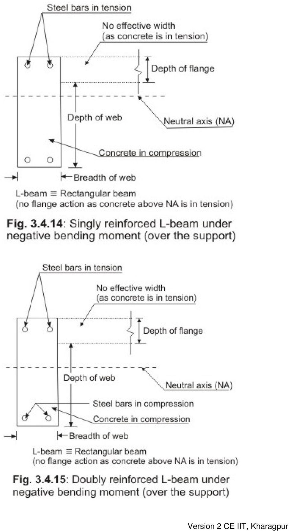
7 During construction of reinforced concrete structures, concrete slabs and beams are cast monolithic making the beams a part of the floor deck system. While bending under positive moments near midspan, bending compression stresses at the top are taken by the rectangular section of the beams above the neutral axis and the slabs, if present in T or L-beams (Figs , 5, 8, 9, 12 and 13). However, under the negative moment over the support or elsewhere, the bending compression stresses are at the bottom and the rectangular sections of rectangular, T and L-beams below the neutral axis only resist that compression (Figs , 7, 10, 11, 14 and 15). Thus, in a slab-beam system the beam will be

8 considered as rectangular for the negative moment and T for the positive moment. While for the intermediate spans of slabs the beam under positive moment is considered as T, the end span edge beam is considered as L-beam if the slab is not projected on both the sides of the beam. It is worth mentioning that the effective width of flange of these T or L-beams is to be determined which depends on:

9
10 (a) (b) (c) (d) if it is an isolated or continuous beam the distance between points of zero moments in the beam the width of the web the thickness of the flange Reinforced concrete slabs are classified as one-way or two-way depending on if they are spanning in one or two directions (Figs and 17). As a guideline, slabs whose ratio of longer span (l y ) to the shorter span (l x ) is more than two are considered as one-way slabs. One-way slabs also can be designed following the procedure of the design of beams of rectangular crosssection. Again, slabs may be isolated or continuous also.

11 3.4.2 Assumptions
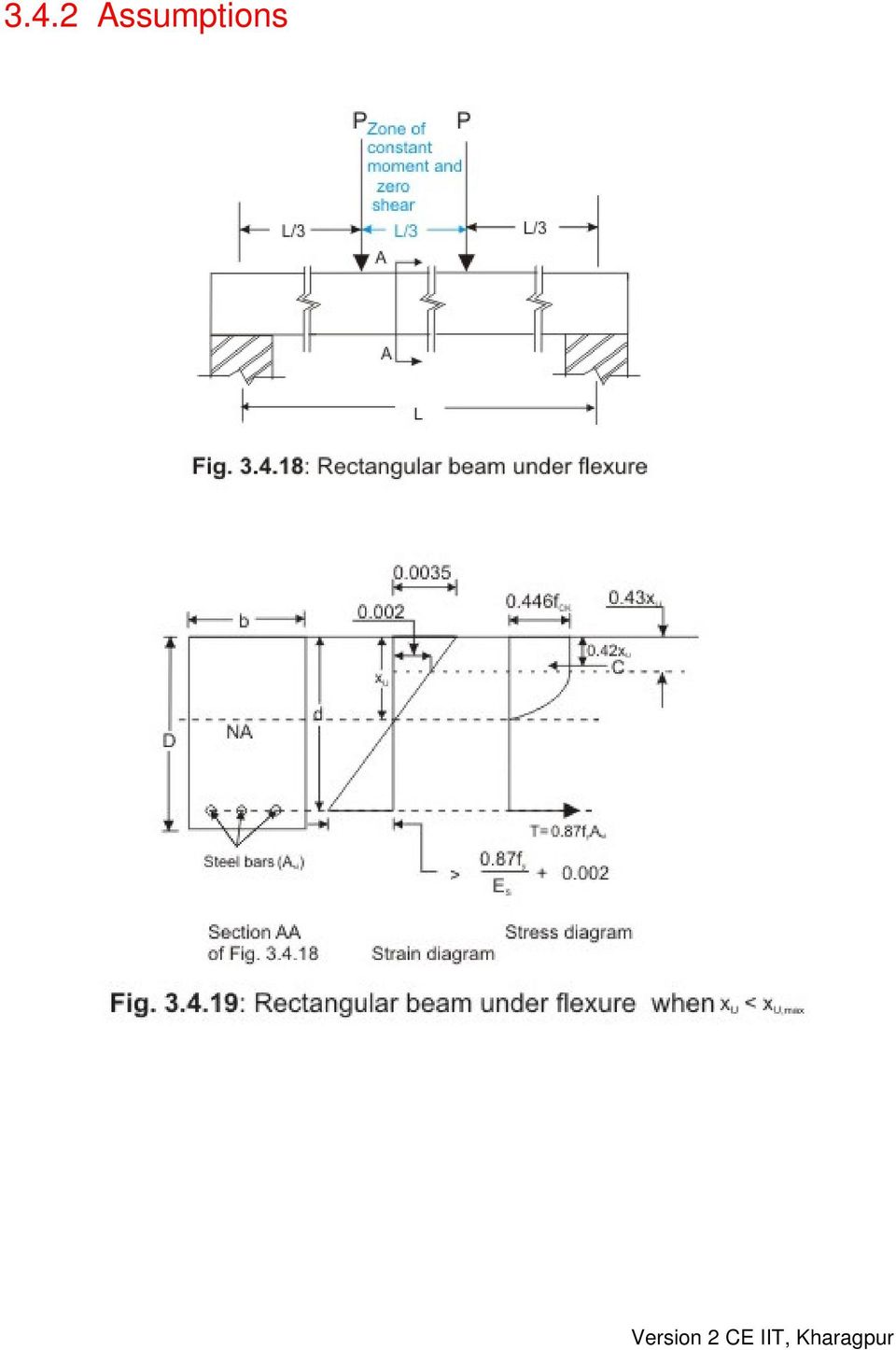
12 The following are the assumptions of the design of flexural members (Figs to 20) employing limit state of collapse: (i) Plane sections normal to the axis remain plane after bending. This assumption ensures that the cross-section of the member does not warp due to the loads applied. It further means that the strain at any point on the cross-section is directly proportional to its distance from the neutral axis. (ii) The maximum strain in concrete at the outer most compression fibre is taken as in bending (Figs and 20). This is a clearly defined limiting strain of concrete in bending compression beyond which the concrete will be taken as reaching the state of collapse. It is very clear that the specified limiting strain of does not depend on the strength of concrete. (iii) The acceptable stress-strain curve of concrete is assumed to be parabolic as shown in Fig of Lesson 2. The maximum compressive stress-strain curve in the structure is obtained by reducing the values of the top parabolic curve (Figs. 21 of IS 456:2000) in two stages. First, dividing by 1.5 due to size effect and secondly, again dividing by 1.5 considering the partial safety factor of the material. The middle and bottom curves (Fig. 21 of IS 456:2000) represent these stages. Thus, the maximum compressive stress in bending is limited to the constant value of f ck for the strain ranging from to (Figs and 20, Figs. 21 and 22 of IS 456:2000).
 The maximum strain in concrete at the outer most compression fibre is taken as 0.0035 in bending (Figs. 3.4.19 and 20).")
13 (iv) The tensile strength of concrete is ignored. Concrete has some tensile strength (very small but not zero). Yet, this tensile strength is ignored and the steel reinforcement is assumed to resist the tensile stress. However, the tensile strength of concrete is taken into account to check the deflection and crack widths in the limit state of serviceability. (v) The design stresses of the reinforcement are derived from the representative stress-strain curves as shown in Figs and 4 of Lesson 2 and Figs. 23A and B of IS 456:2000, for the type of steel used using the partial safety factor γ m as In the reinforced concrete structures, two types of steel are used: one with definite yield point (mild steel, Figs of Lesson 2 and Figs. 23B of IS 456:2000) and the other where the yield points are not definite (cold work deformed bars). The representative stress-strain diagram (Fig of Lesson 2 and Fig. 23A of IS 456:2000) defines the points between 0.8 f y and 1.0 f y in case of cold work deformed bars where the curve is inelastic. (vi) The maximum strain in the tension reinforcement in the section at failure shall not be less than f y /(1.15 E s ) , where f y is the characteristic strength of steel and E s = modulus of elasticity of steel (Figs and 20). This assumption ensures ductile failure in which the tensile reinforcement undergoes a certain degree of inelastic deformation before concrete fails in compression Singly Reinforce Rectangular Beams Figure shows the singly reinforced rectangular beam in flexure. The following notations are used (Figs and 20): A st = area of tension steel b = width of the beam C = total compressive force of concrete d = effective depth of the beam L = centre to centre distance between supports P = two constant loads acting at a distance of L/3 from the two supports of the beam T = total tensile force of steel x u = depth of neutral axis from the top compression fibre Equations of Equilibrium The cross-sections of the beam under the applied loads as shown in Fig has three types of combinations of shear forces and bending moments: (i)
 The design stresses of the reinforcement are derived from the representative stress-strain curves as shown in Figs. 1.2.3 and 4 of Lesson 2 and Figs.")
14 only shear force is there at the support and bending moment is zero, (ii) both bending moment (increasing gradually) and shear force (constant = P) are there between the support and the loading point and (iii) a constant moment (= PL/3) is there in the middle third zone i.e. between the two loads where the shear force is zero (Fig of Lesson 1). Since the beam is in static equilibrium, any crosssection of the beam is also in static equilibrium. Considering the cross-section in the middle zone (Fig ) the three equations of equilibrium are the following (Figs and 20): (i) Equilibrium of horizontal forces: Σ H = 0 gives T = C (3.1) (ii) Equilibrium of vertical shear forces: Σ V = 0 (3.2) This equation gives an identity 0 = 0 as there is no shear in the middle third zone of the beam. (iii) Equilibrium of moments: Σ M = 0, (3.3) This equation shows that the applied moment at the section is fully resisted by moment of the resisting couple T a = C a, where a is the operating lever arm between T and C (Figs and 20) Computations of C and T
 the three equations of equilibrium are the following (Figs. 3.4.19 and 20): (i) Equilibrium of horizontal forces: Σ H = 0 gives T = C (3.1) (ii) Equilibrium of vertical shear forces: Σ V = 0 (3.")
15 Figures a and b present the enlarged view of the compressive part of the strain and stress diagrams. The convex parabolic part of the stress block of Fig b is made rectangular by dotted lines to facilitate the calculations adding another concave parabolic stress zone which is really non-existent as marked by hatch in Fig b. The different compressive forces C, C 1, C 2 and C 3 and distances x 1 to x 5 and x u as marked in Fig b are explained in the following: C = Total compressive force of concrete = C 1 + C 2 C 1 = Compressive force of concrete due to the constant stress of f ck and up to a depth of x 3 from the top fibre C 2 = Compressive force of concrete due to the convex parabolic stress block of values ranging from zero at the neutral axis to f ck at a distance of x 3 from the top fibre C 3 = Compressive force of concrete due to the concave parabolic stress block (actually non-existent) of values ranging from f ck at the neutral axis to zero at a distance of x 3 from the top fibre x 1 = Distance of the line of action of C 1 from the top compressive fibre x 2 = Distance of the line of action of C (= C 1 + C 2 ) from the top compressive fibre x 3 = Distance of the fibre from the top compressive fibre, where the strain = and stress = f ck x 4 = Distance of the line of action of C 2 from the top compressive fibre x 5 = Distance of the line of action of C 3 from the top compressive fibre x u = Distance of the neutral axis from the top compressive fibre. From the strain triangle of Fig a, we have xu xu x3 = = 4 7 = 0. 57, giving (3.4) x 3 = 0.43 x u Since C 1 is due to the constant stress acting from the top to a distance of x 3, the distance x 1 of the line of action of C 1 is:
 of values ranging from 0.")
16 (3.5) x 1 = 0.5 x 3 = x u From Fig a: x 5 = x (x u - x 3 ) = 0.43 x u (0.57 x u ) or (3.6) x 5 = 0.86 x u The compressive force C 1 due to the rectangular stress block is: (3.7) C 1 = b x 3 (0.446 f ck ) = b x u f ck The compressive force C 2 due to parabolic stress block is: (3.8) C 2 = b (x u - x 3 ) 3 2 (0.446 f ck ) = 0.17 b x u f ck Adding C 1 and C 2, we have (3.9) C = C 1 + C 2 = b x u f ck = 0.36 b x u f ck (say) The non-existent compressive force C 3 due to parabolic (concave) stress block is: (3.10) C 3 = b (x u - x 3 ) 3 1 (0.446 f ck ) = b x u f ck Now, we can get x 4 by taking moment of C 2 and C 3 about the top fibre as follows: C 2 (x 4 ) + C 3 (x 5 ) = (C 2 + C 3 ) (x 3 + x u x 3 ) 2 which gives x 4 = 0.64 x u (3.11) Similarly, x 2 is obtained by taking moment of C 1 and C 2 about the top fibre as follows: C 1 (x 1 ) + C 2 (x 4 ) = C(x 2 ) which gives x 2 = x u
 The non-existent compressive force C 3 due to parabolic (concave) stress block is: (3.10) C 3 = b (x u - x 3 ) 3 1 (0.446 f ck ) = 0.")
17 or (3.12) x 2 = 0.42 x u (say). Thus, the required parameters of the stress block (Fig ) are C = 0.36 b x u f ck (3.9) x 2 = 0.42 x u (3.12) and lever arm = (d - x 2 ) = (d x u ) (3.13) The tensile force T is obtained by multiplying the design stress of steel with the area of steel. Thus, (3.14) T = f y ( ) Ast = f y Ast Practice Questions and Problems with Answers Q.1: How do the beams and slabs primarily carry the transverse loads? A.1: Q.2: A.2: The beams and slabs carry the transverse loads primarily by bending. Name three different types of reinforced concrete beams and their specific applications. They are: (i) (ii) Singly reinforced and doubly reinforced rectangular beams - used in resisting negative moments in intermediate spans of continuous beams over the supports or elsewhere in slab-beam monolithic constructions, and positive moments in midspan of isolated or intermediate spans of beams with inverted slab (monolithic) constructions and lintels. Singly reinforced and doubly reinforced T-beams - used in resisting positive moments in isolated or intermediate spans (midspan) in slab-beam monolithic constructions and negative moments over the support for continuous spans with inverted slab (monolithic) constructions.

18 (iii) Singly reinforced and doubly reinforced L-beams - Same as (ii) above except that these are for end spans instead of intermediate spans. Q.3: Name four parameters which determine the effective widths of T and L- beams. A.3: The four parameters are: (i) isolated or continuous beams, (ii) the distance between points of zero moments in the beam, (iii) the breadth of the web, (iv) the thickness of the flange. Q.4: A.4: Q.5: A.5: Q.6: Differentiate between one-way and two-way slabs. One-way slab spans in one direction and two-way slab spans in both the directions. Slabs whose ratio of longer span (l y ) to shorter span (l x ) is more than 2 are called one-way. Slabs of this ratio up to 2 are called two-way slabs. State and explain the significance of the six assumptions of design of flexural members employing limit state of collapse. Sec gives the full answer. Draw a cross-section of singly reinforced rectangular beam and show the strain and stress diagrams. A.6: Fig Q.7: Write the three equations of equilibrium needed to design the reinforced concrete beams. A.7: Vide sec and Eqs. 3.1 to 3. Q.8: Write the final expression of the total compressive force C and tensile force T for a rectangular reinforced concrete beam in terms of the designing parameters. A.8: Eq. 3.9 for C and Eq for T.

19 3.4.7 References 1. Reinforced Concrete Limit State Design, 6 th Edition, by Ashok K. Jain, Nem Chand & Bros, Roorkee, Limit State Design of Reinforced Concrete, 2 nd Edition, by P.C.Varghese, Prentice-Hall of India Pvt. Ltd., New Delhi, Advanced Reinforced Concrete Design, by P.C.Varghese, Prentice-Hall of India Pvt. Ltd., New Delhi, Reinforced Concrete Design, 2 nd Edition, by S.Unnikrishna Pillai and Devdas Menon, Tata McGraw-Hill Publishing Company Limited, New Delhi, Limit State Design of Reinforced Concrete Structures, by P.Dayaratnam, Oxford & I.B.H. Publishing Company Pvt. Ltd., New Delhi, Reinforced Concrete Design, 1 st Revised Edition, by S.N.Sinha, Tata McGraw-Hill Publishing Company. New Delhi, Reinforced Concrete, 6 th Edition, by S.K.Mallick and A.P.Gupta, Oxford & IBH Publishing Co. Pvt. Ltd. New Delhi, Behaviour, Analysis & Design of Reinforced Concrete Structural Elements, by I.C.Syal and R.K.Ummat, A.H.Wheeler & Co. Ltd., Allahabad, Reinforced Concrete Structures, 3 rd Edition, by I.C.Syal and A.K.Goel, A.H.Wheeler & Co. Ltd., Allahabad, Textbook of R.C.C, by G.S.Birdie and J.S.Birdie, Wiley Eastern Limited, New Delhi, Design of Concrete Structures, 13 th Edition, by Arthur H. Nilson, David Darwin and Charles W. Dolan, Tata McGraw-Hill Publishing Company Limited, New Delhi, Concrete Technology, by A.M.Neville and J.J.Brooks, ELBS with Longman, Properties of Concrete, 4 th Edition, 1 st Indian reprint, by A.M.Neville, Longman, Reinforced Concrete Designer s Handbook, 10 th Edition, by C.E.Reynolds and J.C.Steedman, E & FN SPON, London, Indian Standard Plain and Reinforced Concrete Code of Practice (4 th Revision), IS 456: 2000, BIS, New Delhi. 16. Design Aids for Reinforced Concrete to IS: , BIS, New Delhi Test 4 with Solutions Maximum Marks = 50, Maximum Time = 30 minutes Answer all questions. TQ.1: Tick the correct answer: (4 x 5 = 20 marks)

20 (i) Beams and slabs carry the transverse loads primarily by (a) truss action (b) balance of shear action (c) bending (d) slab-beam interaction A.TQ.1: (i): (c) (ii) The ratio of longer span (l y ) to shorter span (l x ) of a two-way slab is (a) up to 2 (b) more than 2 (c) equal to 1 (d) more than 1 A.TQ.1: (ii): (a) (iii) An inverted T-beam is considered as a rectangular beam for the design (a) over the intermediate support of a continuous beam where the bending moment is negative (b) at the midspan of a continuous beam where the bending moment is positive (c) at the point of zero bending moment (d) over the support of a simply supported beam A.TQ.1: (iii): (b) (iv) The maximum strain in the tension reinforcement in the section at failure shall be (a) more than f y /(1.15 E s ) (b) equal to (c) more than f y /E s (d) less than f y /(1.15 E s ) A.TQ.1: (iv): (d)
 at the point of zero bending moment (d) over the support of a simply supported beam A.TQ.")
21 TQ.2: Draw a cross-section of singly reinforced rectangular beam and show the strain and stress diagrams. (10) A.TQ.2: Fig TQ.3: Name four parameters which determine the effective widths of T and L- beams. (6) A.TQ.3: The four parameters are: (i) isolated or continuous beams, (ii) the distance between points of zero moments in the beam, (iii) the breadth of the web, (iv) the thickness of the flange. TQ.4: Derive the final expressions of the total compressive force C and tensile force T for a rectangular reinforced concrete beam in terms of the designing parameters. ( = 14) A.TQ.4: Section is the full answer Summary of this Lesson Lesson 4 illustrates the primary load carrying principle in a slab-beam structural system subjected to transverse loadings. It also mentions three different types of singly and doubly reinforced beams normally used in construction. Various assumptions made in the design of these beams employing limit state of collapse are explained. The stress and strain diagrams of a singly reinforced rectangular beam are explained to write down the three equations of equilibrium. Finally, the computations of the total compressive and tensile forces are illustrated.
16. Beam-and-Slab Design
 ENDP311 Structural Concrete Design 16. Beam-and-Slab Design Beam-and-Slab System How does the slab work? L- beams and T- beams Holding beam and slab together University of Western Australia School of Civil
INTRODUCTION TO BEAMS
 CHAPTER Structural Steel Design LRFD Method INTRODUCTION TO BEAMS Third Edition A. J. Clark School of Engineering Department of Civil and Environmental Engineering Part II Structural Steel Design and Analysis
DESIGN OF SLABS. Department of Structures and Materials Engineering Faculty of Civil and Environmental Engineering University Tun Hussein Onn Malaysia
 DESIGN OF SLABS Department of Structures and Materials Engineering Faculty of Civil and Environmental Engineering University Tun Hussein Onn Malaysia Introduction Types of Slab Slabs are plate elements
SLAB DESIGN. Introduction ACI318 Code provides two design procedures for slab systems:
 Reading Assignment SLAB DESIGN Chapter 9 of Text and, Chapter 13 of ACI318-02 Introduction ACI318 Code provides two design procedures for slab systems: 13.6.1 Direct Design Method (DDM) For slab systems
SEISMIC DESIGN. Various building codes consider the following categories for the analysis and design for earthquake loading:
 SEISMIC DESIGN Various building codes consider the following categories for the analysis and design for earthquake loading: 1. Seismic Performance Category (SPC), varies from A to E, depending on how the
DESIGN OF SLABS. 3) Based on support or boundary condition: Simply supported, Cantilever slab,
 Based on support or boundary condition: Simply supported, Cantilever slab,") DESIGN OF SLABS Dr. G. P. Chandradhara Professor of Civil Engineering S. J. College of Engineering Mysore 1. GENERAL A slab is a flat two dimensional planar structural element having thickness small compared
DESIGN OF SLABS Dr. G. P. Chandradhara Professor of Civil Engineering S. J. College of Engineering Mysore 1. GENERAL A slab is a flat two dimensional planar structural element having thickness small compared
Chapter 8. Flexural Analysis of T-Beams
 Chapter 8. Flexural Analysis of T-s 8.1. Reading Assignments Text Chapter 3.7; ACI 318, Section 8.10. 8.2. Occurrence and Configuration of T-s Common construction type.- used in conjunction with either
The following sketches show the plans of the two cases of one-way slabs. The spanning direction in each case is shown by the double headed arrow.
 9.2 One-way Slabs This section covers the following topics. Introduction Analysis and Design 9.2.1 Introduction Slabs are an important structural component where prestressing is applied. With increase
SECTION 3 DESIGN OF POST- TENSIONED COMPONENTS FOR FLEXURE
 SECTION 3 DESIGN OF POST- TENSIONED COMPONENTS FOR FLEXURE DEVELOPED BY THE PTI EDC-130 EDUCATION COMMITTEE LEAD AUTHOR: TREY HAMILTON, UNIVERSITY OF FLORIDA NOTE: MOMENT DIAGRAM CONVENTION In PT design,
SECTION 3 DESIGN OF POST TENSIONED COMPONENTS FOR FLEXURE
 SECTION 3 DESIGN OF POST TENSIONED COMPONENTS FOR FLEXURE DEVELOPED BY THE PTI EDC-130 EDUCATION COMMITTEE LEAD AUTHOR: TREY HAMILTON, UNIVERSITY OF FLORIDA NOTE: MOMENT DIAGRAM CONVENTION In PT design,
MATERIALS AND MECHANICS OF BENDING
 HAPTER Reinforced oncrete Design Fifth Edition MATERIALS AND MEHANIS OF BENDING A. J. lark School of Engineering Department of ivil and Environmental Engineering Part I oncrete Design and Analysis b FALL
Department of Civil Engineering B.TECH 5 TH SEM Lecture Notes on STRUCTURAL DESIGN BCE301
 Department of Civil Engineering B.TECH 5 TH SEM Lecture Notes on STRUCTURAL DESIGN BCE301 Disclaimer This document does not claim any originality and cannot be used as a substitute for prescribed textbooks.
Technical Notes 3B - Brick Masonry Section Properties May 1993
 Technical Notes 3B - Brick Masonry Section Properties May 1993 Abstract: This Technical Notes is a design aid for the Building Code Requirements for Masonry Structures (ACI 530/ASCE 5/TMS 402-92) and Specifications
Draft Table of Contents. Building Code Requirements for Structural Concrete and Commentary ACI 318-14
 Draft Table of Contents Building Code Requirements for Structural Concrete and Commentary ACI 318-14 BUILDING CODE REQUIREMENTS FOR STRUCTURAL CONCRETE (ACI 318 14) Chapter 1 General 1.1 Scope of ACI 318
Optimum proportions for the design of suspension bridge
 Journal of Civil Engineering (IEB), 34 (1) (26) 1-14 Optimum proportions for the design of suspension bridge Tanvir Manzur and Alamgir Habib Department of Civil Engineering Bangladesh University of Engineering
Design of Steel Structures Prof. S.R.Satish Kumar and Prof. A.R.Santha Kumar. Fig. 7.21 some of the trusses that are used in steel bridges
 7.7 Truss bridges Fig. 7.21 some of the trusses that are used in steel bridges Truss Girders, lattice girders or open web girders are efficient and economical structural systems, since the members experience
Stress Strain Relationships
 Stress Strain Relationships Tensile Testing One basic ingredient in the study of the mechanics of deformable bodies is the resistive properties of materials. These properties relate the stresses to the
Spon Press PRESTRESSED CONCRETE DESIGN EUROCODES. University of Glasgow. Department of Civil Engineering. Prabhakara Bhatt LONDON AND NEW YORK
 PRESTRESSED CONCRETE DESIGN TO EUROCODES Prabhakara Bhatt Department of Civil Engineering University of Glasgow Spon Press an imprint of Taytor & Francfe LONDON AND NEW YORK CONTENTS Preface xix Basic
Reinforced Concrete Design Project Five Story Office Building
 Reinforced Concrete Design Project Five Story Office Building Andrew Bartolini December 7, 2012 Designer 1 Partner: Shannon Warchol CE 40270: Reinforced Concrete Design Bartolini 2 Table of Contents Abstract...3
Reinforced Concrete Design
 FALL 2013 C C Reinforced Concrete Design CIVL 4135 ii 1 Chapter 1. Introduction 1.1. Reading Assignment Chapter 1 Sections 1.1 through 1.8 of text. 1.2. Introduction In the design and analysis of reinforced
Design Analysis and Review of Stresses at a Point
 Design Analysis and Review of Stresses at a Point Need for Design Analysis: To verify the design for safety of the structure and the users. To understand the results obtained in FEA, it is necessary to
Deflection Calculation of RC Beams: Finite Element Software Versus Design Code Methods
 Deflection Calculation of RC Beams: Finite Element Software Versus Design Code Methods G. Kaklauskas, Vilnius Gediminas Technical University, 1223 Vilnius, Lithuania (gintaris.kaklauskas@st.vtu.lt) V.
Numerical modelling of shear connection between concrete slab and sheeting deck
 7th fib International PhD Symposium in Civil Engineering 2008 September 10-13, Universität Stuttgart, Germany Numerical modelling of shear connection between concrete slab and sheeting deck Noémi Seres
Stresses in Beam (Basic Topics)
") Chapter 5 Stresses in Beam (Basic Topics) 5.1 Introduction Beam : loads acting transversely to the longitudinal axis the loads create shear forces and bending moments, stresses and strains due to V and
Chapter 5 Stresses in Beam (Basic Topics) 5.1 Introduction Beam : loads acting transversely to the longitudinal axis the loads create shear forces and bending moments, stresses and strains due to V and
MECHANICS OF SOLIDS - BEAMS TUTORIAL 2 SHEAR FORCE AND BENDING MOMENTS IN BEAMS
 MECHANICS OF SOLIDS - BEAMS TUTORIAL 2 SHEAR FORCE AND BENDING MOMENTS IN BEAMS This is the second tutorial on bending of beams. You should judge your progress by completing the self assessment exercises.
ENGINEERING SCIENCE H1 OUTCOME 1 - TUTORIAL 3 BENDING MOMENTS EDEXCEL HNC/D ENGINEERING SCIENCE LEVEL 4 H1 FORMERLY UNIT 21718P
 ENGINEERING SCIENCE H1 OUTCOME 1 - TUTORIAL 3 BENDING MOMENTS EDEXCEL HNC/D ENGINEERING SCIENCE LEVEL 4 H1 FORMERLY UNIT 21718P This material is duplicated in the Mechanical Principles module H2 and those
SECTION 5 ANALYSIS OF CONTINUOUS SPANS DEVELOPED BY THE PTI EDC-130 EDUCATION COMMITTEE LEAD AUTHOR: BRYAN ALLRED
 SECTION 5 ANALYSIS OF CONTINUOUS SPANS DEVELOPED BY THE PTI EDC-130 EDUCATION COMMITTEE LEAD AUTHOR: BRYAN ALLRED NOTE: MOMENT DIAGRAM CONVENTION In PT design, it is preferable to draw moment diagrams
8.2 Elastic Strain Energy
 Section 8. 8. Elastic Strain Energy The strain energy stored in an elastic material upon deformation is calculated below for a number of different geometries and loading conditions. These expressions for
Chapter - 3 Design of Rectangular Beams and One-way Slabs
 Rectangular Beams and One-way Slabs Page 1 of 9 Chapter - 3 Design of Rectangular Beams and One-way Slabs 12 h A 12 strip in a simply supported one-way slab h b=12 L Rectangular Beams and One-way Slabs
A transverse strip of the deck is assumed to support the truck axle loads. Shear and fatigue of the reinforcement need not be investigated.
 Design Step 4 Design Step 4.1 DECK SLAB DESIGN In addition to designing the deck for dead and live loads at the strength limit state, the AASHTO-LRFD specifications require checking the deck for vehicular
9.3 Two-way Slabs (Part I)
") 9.3 Two-way Slabs (Part I) This section covers the following topics. Introduction Analysis and Design Features in Modeling and Analysis Distribution of Moments to Strips 9.3.1 Introduction The slabs are
9.3 Two-way Slabs (Part I) This section covers the following topics. Introduction Analysis and Design Features in Modeling and Analysis Distribution of Moments to Strips 9.3.1 Introduction The slabs are
MECHANICS OF SOLIDS - BEAMS TUTORIAL 1 STRESSES IN BEAMS DUE TO BENDING. On completion of this tutorial you should be able to do the following.
 MECHANICS OF SOLIDS - BEAMS TUTOIAL 1 STESSES IN BEAMS DUE TO BENDING This is the first tutorial on bending of beams designed for anyone wishing to study it at a fairly advanced level. You should judge
Design of reinforced concrete columns. Type of columns. Failure of reinforced concrete columns. Short column. Long column
 Design of reinforced concrete columns Type of columns Failure of reinforced concrete columns Short column Column fails in concrete crushed and bursting. Outward pressure break horizontal ties and bend
Torsion Tests. Subjects of interest
 Chapter 10 Torsion Tests Subjects of interest Introduction/Objectives Mechanical properties in torsion Torsional stresses for large plastic strains Type of torsion failures Torsion test vs.tension test
Introduction to Beam. Area Moments of Inertia, Deflection, and Volumes of Beams
 Introduction to Beam Theory Area Moments of Inertia, Deflection, and Volumes of Beams Horizontal structural member used to support horizontal loads such as floors, roofs, and decks. Types of beam loads
Bending, Forming and Flexing Printed Circuits
 Bending, Forming and Flexing Printed Circuits John Coonrod Rogers Corporation Introduction: In the printed circuit board industry there are generally two main types of circuit boards; there are rigid printed
Flexural Strength of Reinforced and Prestressed Concrete T-Beams
 Flexural Strength of Reinforced and Prestressed Concrete T-Beams Richard Brice, P.E. Bridge Software Engineer Bridge & Structures Office Washington State Department of Transportation Olympia, Washington
Statics of Structural Supports
 Statics of Structural Supports TYPES OF FORCES External Forces actions of other bodies on the structure under consideration. Internal Forces forces and couples exerted on a member or portion of the structure
Module 2. Analysis of Statically Indeterminate Structures by the Matrix Force Method. Version 2 CE IIT, Kharagpur
 Module Analysis of Statically Indeterminate Structures by the Matrix Force Method esson 11 The Force Method of Analysis: Frames Instructional Objectives After reading this chapter the student will be able
ADVANTAGES OF STEEL FIBRE REINFORCED CONCRETE IN INDUSTRIAL FLOORS
 ADVANTAGES OF STEEL FIBRE REINFORCED CONCRETE IN INDUSTRIAL FLOORS Murugesan M 1, Dashrath Rajpurohit 2 1 Assistant General Manager, Civil & Structural, Larsen & Toubro Technology Services, Tamilnadu,
Concrete Frame Design Manual
 Concrete Frame Design Manual Turkish TS 500-2000 with Turkish Seismic Code 2007 For SAP2000 ISO SAP093011M26 Rev. 0 Version 15 Berkeley, California, USA October 2011 COPYRIGHT Copyright Computers and Structures,
B.TECH. (AEROSPACE ENGINEERING) PROGRAMME (BTAE) Term-End Examination December, 2011 BAS-010 : MACHINE DESIGN
 PROGRAMME (BTAE) Term-End Examination December, 2011 BAS-010 : MACHINE DESIGN") No. of Printed Pages : 7 BAS-01.0 B.TECH. (AEROSPACE ENGINEERING) PROGRAMME (BTAE) CV CA CV C:) O Term-End Examination December, 2011 BAS-010 : MACHINE DESIGN Time : 3 hours Maximum Marks : 70 Note : (1)
No. of Printed Pages : 7 BAS-01.0 B.TECH. (AEROSPACE ENGINEERING) PROGRAMME (BTAE) CV CA CV C:) O Term-End Examination December, 2011 BAS-010 : MACHINE DESIGN Time : 3 hours Maximum Marks : 70 Note : (1)
Figure 5-11. Test set-up
 5.5. Load Procedure A uniform load configuration was used for the load tests. An air bag, placed on the top surface of the slab, was used for this purpose, and the load was applied by gradually increasing
SEISMIC UPGRADE OF OAK STREET BRIDGE WITH GFRP
 13 th World Conference on Earthquake Engineering Vancouver, B.C., Canada August 1-6, 2004 Paper No. 3279 SEISMIC UPGRADE OF OAK STREET BRIDGE WITH GFRP Yuming DING 1, Bruce HAMERSLEY 2 SUMMARY Vancouver
STRESS AND DEFORMATION ANALYSIS OF LINEAR ELASTIC BARS IN TENSION
 Chapter 11 STRESS AND DEFORMATION ANALYSIS OF LINEAR ELASTIC BARS IN TENSION Figure 11.1: In Chapter10, the equilibrium, kinematic and constitutive equations for a general three-dimensional solid deformable
Design of Fibre Reinforced Concrete Beams and Slabs
 Design of Fibre Reinforced Concrete Beams and Slabs Master of Science Thesis in the Master s Programme Structural Engineering and Building Performance Design AMMAR ABID, KENNETH B. FRANZÉN Department of
Introduction to Mechanical Behavior of Biological Materials
 Introduction to Mechanical Behavior of Biological Materials Ozkaya and Nordin Chapter 7, pages 127-151 Chapter 8, pages 173-194 Outline Modes of loading Internal forces and moments Stiffness of a structure
Detailing of Reinforcment in Concrete Structures
 Chapter 8 Detailing of Reinforcment in Concrete Structures 8.1 Scope Provisions of Sec. 8.1 and 8.2 of Chapter 8 shall apply for detailing of reinforcement in reinforced concrete members, in general. For
1.5 Concrete (Part I)
") 1.5 Concrete (Part I) This section covers the following topics. Constituents of Concrete Properties of Hardened Concrete (Part I) 1.5.1 Constituents of Concrete Introduction Concrete is a composite material
1.5 Concrete (Part I) This section covers the following topics. Constituents of Concrete Properties of Hardened Concrete (Part I) 1.5.1 Constituents of Concrete Introduction Concrete is a composite material
Type of Force 1 Axial (tension / compression) Shear. 3 Bending 4 Torsion 5 Images 6 Symbol (+ -)
 Shear. 3 Bending 4 Torsion 5 Images 6 Symbol (+ -)") Cause: external force P Force vs. Stress Effect: internal stress f 05 Force vs. Stress Copyright G G Schierle, 2001-05 press Esc to end, for next, for previous slide 1 Type of Force 1 Axial (tension /
Cause: external force P Force vs. Stress Effect: internal stress f 05 Force vs. Stress Copyright G G Schierle, 2001-05 press Esc to end, for next, for previous slide 1 Type of Force 1 Axial (tension /
Deflections. Question: What are Structural Deflections?
 Question: What are Structural Deflections? Answer: The deformations or movements of a structure and its components, such as beams and trusses, from their original positions. It is as important for the
Approximate Analysis of Statically Indeterminate Structures
 Approximate Analysis of Statically Indeterminate Structures Every successful structure must be capable of reaching stable equilibrium under its applied loads, regardless of structural behavior. Exact analysis
Aluminium systems profile selection
 Aluminium systems profile selection The purpose of this document is to summarise the way that aluminium profile selection should be made, based on the strength requirements for each application. Curtain
The elements used in commercial codes can be classified in two basic categories:
 CHAPTER 3 Truss Element 3.1 Introduction The single most important concept in understanding FEA, is the basic understanding of various finite elements that we employ in an analysis. Elements are used for
Optimising plate girder design
 Optimising plate girder design NSCC29 R. Abspoel 1 1 Division of structural engineering, Delft University of Technology, Delft, The Netherlands ABSTRACT: In the design of steel plate girders a high degree
Structural Axial, Shear and Bending Moments
 Structural Axial, Shear and Bending Moments Positive Internal Forces Acting Recall from mechanics of materials that the internal forces P (generic axial), V (shear) and M (moment) represent resultants
Seismic design of beam-column joints in RC moment resisting frames Review of codes
 Structural Engineering and Mechanics, Vol. 23, No. 5 (2006) 579-597 579 Technical Report Seismic design of beam-column joints in RC moment resisting frames Review of codes S. R. Uma Department of Civil
New approaches in Eurocode 3 efficient global structural design
 New approaches in Eurocode 3 efficient global structural design Part 1: 3D model based analysis using general beam-column FEM Ferenc Papp* and József Szalai ** * Associate Professor, Department of Structural
bi directional loading). Prototype ten story
. Prototype ten story") NEESR SG: Behavior, Analysis and Design of Complex Wall Systems The laboratory testing presented here was conducted as part of a larger effort that employed laboratory testing and numerical simulation
NEESR SG: Behavior, Analysis and Design of Complex Wall Systems The laboratory testing presented here was conducted as part of a larger effort that employed laboratory testing and numerical simulation
FOOTING DESIGN EXAMPLE
 County: Any Design: BRG Date: 10/007 Hwy: Any Ck Dsn: BRG Date: 10/007 FOOTING DESIGN EXAMPLE Design: Based on AASHTO LRFD 007 Specifications, TxDOT LRFD Bridge Design Manual, and TxDOT Project 0-4371
Objectives. Experimentally determine the yield strength, tensile strength, and modules of elasticity and ductility of given materials.
 Lab 3 Tension Test Objectives Concepts Background Experimental Procedure Report Requirements Discussion Objectives Experimentally determine the yield strength, tensile strength, and modules of elasticity
Section 16: Neutral Axis and Parallel Axis Theorem 16-1
 Section 16: Neutral Axis and Parallel Axis Theorem 16-1 Geometry of deformation We will consider the deformation of an ideal, isotropic prismatic beam the cross section is symmetric about y-axis All parts
Sheet metal operations - Bending and related processes
 Sheet metal operations - Bending and related processes R. Chandramouli Associate Dean-Research SASTRA University, Thanjavur-613 401 Table of Contents 1.Quiz-Key... Error! Bookmark not defined. 1.Bending
PRESTRESSED CONCRETE. Introduction REINFORCED CONCRETE CHAPTER SPRING 2004. Reinforced Concrete Design. Fifth Edition. By Dr. Ibrahim.
 CHAPTER REINFORCED CONCRETE Reinforced Concrete Design A Fundamental Approach - Fifth Edition Fifth Edition PRESTRESSED CONCRETE A. J. Clark School of Engineering Department of Civil and Environmental
Preliminary steel concrete composite bridge design charts for Eurocodes
 Preliminary steel concrete composite bridge 90 Rachel Jones Senior Engineer Highways & Transportation Atkins David A Smith Regional Head of Bridge Engineering Highways & Transportation Atkins Abstract
Bending Stress in Beams
 936-73-600 Bending Stress in Beams Derive a relationship for bending stress in a beam: Basic Assumptions:. Deflections are very small with respect to the depth of the beam. Plane sections before bending
Finite Element Simulation of Simple Bending Problem and Code Development in C++
 EUROPEAN ACADEMIC RESEARCH, VOL. I, ISSUE 6/ SEPEMBER 013 ISSN 86-48, www.euacademic.org IMPACT FACTOR: 0.485 (GIF) Finite Element Simulation of Simple Bending Problem and Code Development in C++ ABDUL
SPECIFICATIONS, LOADS, AND METHODS OF DESIGN
 CHAPTER Structural Steel Design LRFD Method Third Edition SPECIFICATIONS, LOADS, AND METHODS OF DESIGN A. J. Clark School of Engineering Department of Civil and Environmental Engineering Part II Structural
Overhang Bracket Loading. Deck Issues: Design Perspective
 Deck Issues: Design Perspective Overhang Bracket Loading Deck overhangs and screed rails are generally supported on cantilever brackets during the deck pour These brackets produce an overturning couple
MECHANICS OF SOLIDS - BEAMS TUTORIAL TUTORIAL 4 - COMPLEMENTARY SHEAR STRESS
 MECHANICS OF SOLIDS - BEAMS TUTORIAL TUTORIAL 4 - COMPLEMENTARY SHEAR STRESS This the fourth and final tutorial on bending of beams. You should judge our progress b completing the self assessment exercises.
ETABS. Integrated Building Design Software. Concrete Frame Design Manual. Computers and Structures, Inc. Berkeley, California, USA
 ETABS Integrated Building Design Software Concrete Frame Design Manual Computers and Structures, Inc. Berkeley, California, USA Version 8 January 2002 Copyright The computer program ETABS and all associated
Design MEMO 54a Reinforcement design for RVK 41
 Page of 5 CONTENTS PART BASIC ASSUMTIONS... 2 GENERAL... 2 STANDARDS... 2 QUALITIES... 3 DIMENSIONS... 3 LOADS... 3 PART 2 REINFORCEMENT... 4 EQUILIBRIUM... 4 Page 2 of 5 PART BASIC ASSUMTIONS GENERAL
APPENDIX H DESIGN CRITERIA FOR NCHRP 12-79 PROJECT NEW BRIDGE DESIGNS
 APPENDIX H DESIGN CRITERIA FOR NCHRP 12-79 PROJECT NEW BRIDGE DESIGNS This appendix summarizes the criteria applied for the design of new hypothetical bridges considered in NCHRP 12-79 s Task 7 parametric
1.054/1.541 Mechanics and Design of Concrete Structures (3-0-9) Outline 1 Introduction / Design Criteria for Reinforced Concrete Structures
 Outline 1 Introduction / Design Criteria for Reinforced Concrete Structures") Prof. Oral Buyukozturk Massachusetts Institute of Technology Outline 1 1.054/1.541 Mechanics and Design of Concrete Structures (3-0-9) Outline 1 Introduction / Design Criteria for Reinforced Concrete Structures
Prof. Oral Buyukozturk Massachusetts Institute of Technology Outline 1 1.054/1.541 Mechanics and Design of Concrete Structures (3-0-9) Outline 1 Introduction / Design Criteria for Reinforced Concrete Structures
Shear Forces and Bending Moments
 Chapter 4 Shear Forces and Bending Moments 4.1 Introduction Consider a beam subjected to transverse loads as shown in figure, the deflections occur in the plane same as the loading plane, is called the
ANALYSIS FOR BEHAVIOR AND ULTIMATE STRENGTH OF CONCRETE CORBELS WITH HYBRID REINFORCEMENT
 International Journal of Civil Engineering and Technology (IJCIET) Volume 6, Issue 10, Oct 2015, pp. 25-35 Article ID: IJCIET_06_10_003 Available online at http://www.iaeme.com/ijciet/issues.asp?jtype=ijciet&vtype=6&itype=10
Problem 1: Computation of Reactions. Problem 2: Computation of Reactions. Problem 3: Computation of Reactions
 Problem 1: Computation of Reactions Problem 2: Computation of Reactions Problem 3: Computation of Reactions Problem 4: Computation of forces and moments Problem 5: Bending Moment and Shear force Problem
EVALUATION OF SEISMIC RESPONSE - FACULTY OF LAND RECLAMATION AND ENVIRONMENTAL ENGINEERING -BUCHAREST
 EVALUATION OF SEISMIC RESPONSE - FACULTY OF LAND RECLAMATION AND ENVIRONMENTAL ENGINEERING -BUCHAREST Abstract Camelia SLAVE University of Agronomic Sciences and Veterinary Medicine of Bucharest, 59 Marasti
ETABS. Integrated Building Design Software. Composite Floor Frame Design Manual. Computers and Structures, Inc. Berkeley, California, USA
 ETABS Integrated Building Design Software Composite Floor Frame Design Manual Computers and Structures, Inc. Berkeley, California, USA Version 8 January 2002 Copyright The computer program ETABS and all
STEEL BUILDINGS IN EUROPE. Multi-Storey Steel Buildings Part 10: Guidance to developers of software for the design of composite beams
 STEEL BUILDINGS IN EUROPE Multi-Storey Steel Buildings Part 10: Guidance to developers of software for the design of Multi-Storey Steel Buildings Part 10: Guidance to developers of software for the design
Canadian Standards Association
 S6S1-10 10.10.2.2 Laterally supported members When continuous lateral support is provided to the compression flange of a member subjected to bending about its major axis, the factored moment resistance,
Design Of Reinforced Concrete Structures ii Two-Way Slabs
 1. Inroduction When the ratio (L/S) is less than 2.0, slab is called two-way slab, as shown in the fig. below. Bending will take place in the two directions in a dish-like form. Accordingly, main reinforcement
MCE380: Measurements and Instrumentation Lab. Chapter 9: Force, Torque and Strain Measurements
 MCE380: Measurements and Instrumentation Lab Chapter 9: Force, Torque and Strain Measurements Topics: Elastic Elements for Force Measurement Dynamometers and Brakes Resistance Strain Gages Holman, Ch.
1997 Uniform Administrative Code Amendment for Earthen Material and Straw Bale Structures Tucson/Pima County, Arizona
 for Earthen Material and Straw Bale Structures SECTION 70 - GENERAL "APPENDIX CHAPTER 7 - EARTHEN MATERIAL STRUCTURES 70. Purpose. The purpose of this chapter is to establish minimum standards of safety
Page 1 of 18 28.4.2008 Sven Alexander Last revised 1.3.2010. SB-Produksjon STATICAL CALCULATIONS FOR BCC 250
 Page 1 of 18 CONTENT PART 1 BASIC ASSUMPTIONS PAGE 1.1 General 1. Standards 1.3 Loads 1. Qualities PART ANCHORAGE OF THE UNITS.1 Beam unit equilibrium 3. Beam unit anchorage in front..1 Check of capacity..
IMPROVING THE STRUT AND TIE METHOD BY INCLUDING THE CONCRETE SOFTENING EFFECT
 International Journal of Civil Engineering and Technology (IJCIET) Volume 7, Issue 2, March-April 2016, pp. 117 127, Article ID: IJCIET_07_02_009 Available online at http://www.iaeme.com/ijciet/issues.asp?jtype=ijciet&vtype=7&itype=2
Unit 6 Plane Stress and Plane Strain
 Unit 6 Plane Stress and Plane Strain Readings: T & G 8, 9, 10, 11, 12, 14, 15, 16 Paul A. Lagace, Ph.D. Professor of Aeronautics & Astronautics and Engineering Systems There are many structural configurations
EDEXCEL NATIONAL CERTIFICATE/DIPLOMA MECHANICAL PRINCIPLES AND APPLICATIONS NQF LEVEL 3 OUTCOME 1 - LOADING SYSTEMS
 EDEXCEL NATIONAL CERTIFICATE/DIPLOMA MECHANICAL PRINCIPLES AND APPLICATIONS NQF LEVEL 3 OUTCOME 1 - LOADING SYSTEMS TUTORIAL 1 NON-CONCURRENT COPLANAR FORCE SYSTEMS 1. Be able to determine the effects
Design MEMO 60 Reinforcement design for TSS 102
 Date: 04.0.0 sss Page of 5 CONTENTS PART BASIC ASSUMTIONS... GENERAL... STANDARDS... QUALITIES... 3 DIMENSIONS... 3 LOADS... 3 PART REINFORCEMENT... 4 EQUILIBRIUM... 4 Date: 04.0.0 sss Page of 5 PART BASIC
Eurocode 2: Design of concrete structures
 Eurocode 2: Design of concrete structures Owen Brooker, The Concrete Centre Introduction The transition to using the Eurocodes is a daunting prospect for engineers, but this needn t be the case. Industry
Module 7 (Lecture 24 to 28) RETAINING WALLS
 RETAINING WALLS") Module 7 (Lecture 24 to 28) RETAINING WALLS Topics 24.1 INTRODUCTION 24.2 GRAVITY AND CANTILEVER WALLS 24.3 PROPORTIONING RETAINING WALLS 24.4 APPLICATION OF LATERAL EARTH PRESSURE THEORIES TO DESIGN 24.5
Module 7 (Lecture 24 to 28) RETAINING WALLS Topics 24.1 INTRODUCTION 24.2 GRAVITY AND CANTILEVER WALLS 24.3 PROPORTIONING RETAINING WALLS 24.4 APPLICATION OF LATERAL EARTH PRESSURE THEORIES TO DESIGN 24.5
1.2 Advantages and Types of Prestressing
 1.2 Advantages and Types of Prestressing This section covers the following topics. Definitions Advantages of Prestressing Limitations of Prestressing Types of Prestressing 1.2.1 Definitions The terms commonly
FOUNDATION DESIGN. Instructional Materials Complementing FEMA 451, Design Examples
 FOUNDATION DESIGN Proportioning elements for: Transfer of seismic forces Strength and stiffness Shallow and deep foundations Elastic and plastic analysis Foundation Design 14-1 Load Path and Transfer to
DEVELOPMENT OF A NEW TEST FOR DETERMINATION OF TENSILE STRENGTH OF CONCRETE BLOCKS
 1 th Canadian Masonry Symposium Vancouver, British Columbia, June -5, 013 DEVELOPMENT OF A NEW TEST FOR DETERMINATION OF TENSILE STRENGTH OF CONCRETE BLOCKS Vladimir G. Haach 1, Graça Vasconcelos and Paulo
ETABS. Integrated Building Design Software. Concrete Shear Wall Design Manual. Computers and Structures, Inc. Berkeley, California, USA
 ETABS Integrated Building Design Software Concrete Shear Wall Design Manual Computers and Structures, Inc. Berkeley, California, USA Version 8 January 2002 Copyright The computer program ETABS and all
Chapter 5 Bridge Deck Slabs. Bridge Engineering 1
 Chapter 5 Bridge Deck Slabs Bridge Engineering 1 Basic types of bridge decks In-situ reinforced concrete deck- (most common type) Pre-cast concrete deck (minimize the use of local labor) Open steel grid
EDEXCEL NATIONAL CERTIFICATE/DIPLOMA MECHANICAL PRINCIPLES AND APPLICATIONS NQF LEVEL 3 OUTCOME 1 - LOADING SYSTEMS TUTORIAL 3 LOADED COMPONENTS
 EDEXCEL NATIONAL CERTIICATE/DIPLOMA MECHANICAL PRINCIPLES AND APPLICATIONS NQ LEVEL 3 OUTCOME 1 - LOADING SYSTEMS TUTORIAL 3 LOADED COMPONENTS 1. Be able to determine the effects of loading in static engineering
Field Damage Inspection and Static Load Test Analysis of Jiamusi Highway Prestressed Concrete Bridge in China
 Advanced Materials Research Vols. 163-167 (2011) pp 1147-1156 Online available since 2010/Dec/06 at www.scientific.net (2011) Trans Tech Publications, Switzerland doi:10.4028/www.scientific.net/amr.163-167.1147
Mechanical Properties of Metals Mechanical Properties refers to the behavior of material when external forces are applied
 Mechanical Properties of Metals Mechanical Properties refers to the behavior of material when external forces are applied Stress and strain fracture or engineering point of view: allows to predict the
REINFORCED CONCRETE STRUCTURE DESIGN ASSISTANT TOOL FOR BEGINNERS. Kang-Kyu Choi
 REINFORCED CONCRETE STRUCTURE DESIGN ASSISTANT TOOL FOR BEGINNERS by Kang-Kyu Choi A Thesis Presented to the FACULTY OF THE SCHOOL OF ARCHITECTURE UNIVERSITY OF SOUTHERN CALIFORNIA In Partial Fulfillment