Magic 8 Ball. Student's name & ID (1): Partner's name & ID (2): Your Section number & TA's name
|
|
|
- Dominick Wiggins
- 7 years ago
- Views:
Transcription
1 MPS Magic 8 Ball Lab Exercise Magic 8 Ball Student's name & ID (1): Partner's name & ID (2): Your Section number & TA's name Notes: You must work on this assignment with your partner. Hand in a printer copy of your software listings for the team. Hand in a neat copy of your circuit schematics for the team. These will be returned to you so that they may be used for reference do not write below this line #1 POINTS (1) (2) TA init. #2 POINTS (1) (2) TA init. #3 POINTS (1) (2) TA init. Grade for performance verification (50% max.) Grade for answers to TA's questions (20% max.) Grade for documentation and appearance (30% max.) TOTAL TOTAL TOTAL Grader's signature: Date:
 (2) TA init. #2 POINTS (1) (2) TA init. #3 POINTS (1) (2) TA init.")
2 Part 1: Introduction to the Magic 8 Ball GOAL By doing this lab assignment, you will learn: 1. Review of basic serial I/O to the terminal. 2. Logic programming PREPARATION Review the C language studio utilities. Review the 8051 hardware port and interrupt features Develop a flowchart for the program you need to write. This will be signed off by your TA and must be included when you turn in your code for the lab. Write a C program that is free from syntax errors (i.e., it should assemble without error messages). INTRODUCTION TO THE MAGIC 8 BALL Programming Tasks For this lab you will be developing an electronic Magic 8 Ball. You will write a program that generates answers to different kinds of questions. The user selects the type of answer that is desired and the answer is displayed on the screen. There are four different types of answers that can be generated. They are: 1. Yes/No: This will output either a yes or no answer. 2. True/False: This will output either true or false. 3. Day of the week: This will randomly select a day of the week. 4. Random Number: This will select a random integer number within any range stated by the user (e.g. a random number between 3 and 7). The program should have a menu that allows the user to select which type of answer will be generated. After the answer is displayed the program should return to the menu. It is not necessary to clear the screen when returning to the menu. The answers that are generated are to be determined randomly. The section below provides a suggestion for developing random values. In order to earn full credit on the project, the answers must be generated randomly. You should first develop a flowchart for the program you need to write. This will be signed off by your TA and must be included when you turn in your code for the lab. The code must be logically written and well commented. This is very important since you will be using this code as the basis of Parts 2 and 3. After being signed off by the TA you will turn in your flowchart from the preparation work and the fully commented copy of your code. Helpful Hints Here are several suggestions to get you started on the project: 1. Start small. Break the project up into several functions and begin by only debugging one at a time. 2. Random number generation. The rand() function can be used to generate a random number. You can also use a free running counter and read in a value, which will be fairly random as well. Page 2

3 Part 2: Interfacing an LCD Screen to the 8051 GOAL By doing this lab assignment, you will learn to: 1. Interface the C8051F120 to a Hitachi HD line LCD display. 2. How the LCD screen operates. 3. Print results on the LCD screen. This will be used to display the answers generated in Part 1. PREPARATION Read Hitachi HD44780U LCD Controller manual Become familiar with the different LCD screen functions included in LCD.c & LCD.h and the example LCDTEST8051.c ( Rewrite your code from Part 1 so that the answers from the program are displayed on the LCD screen. The menu used to select the answer type will still displayed on the UART terminal screen. INTRODUCTION TO THE LCD SCREEN Programming Tasks For this lab you will be adding an LCD screen to the Magic 8 Ball system. This screen will be used to display the answers that are generated by the program. When an answer is written to the screen, the screen should first be cleared and then the answer printed. The answer should remain on the screen until a new answer is generated. A list of the LCD functions is in the LCD.h header file. Helpful Hints: Here are several suggestions to help you with the lab. 1. Remember that all characters to be sent to the screen must be sent as ASCII. This can be done by creating a char * with the character string or by passing in each character separately as an ASCII character. 2. Don t forget to include LCD.h (found on the course web page) in your program. 3. Remember to initialize the screen and make sure you have set the format type (number of lines and character size) to the desired value before trying to use the screen. 4. There are several ways of passing characters to the lcd_puts() function: char buffer[] = Hello. ; lcd_puts(buffer); //But the 2008 SDCC compiler doesn t allow //lcd_puts(buffer[]); OR lcd_puts((char *) & Hello. ); OR char buf; buf = H ; lcd_puts((char *) &buf); 5. Add delays between LCD commands in program if the display doesn t respond correctly every time. Page 3
. Rewrite your code from Part 1 so that the answers from the program are displayed on the LCD screen.")
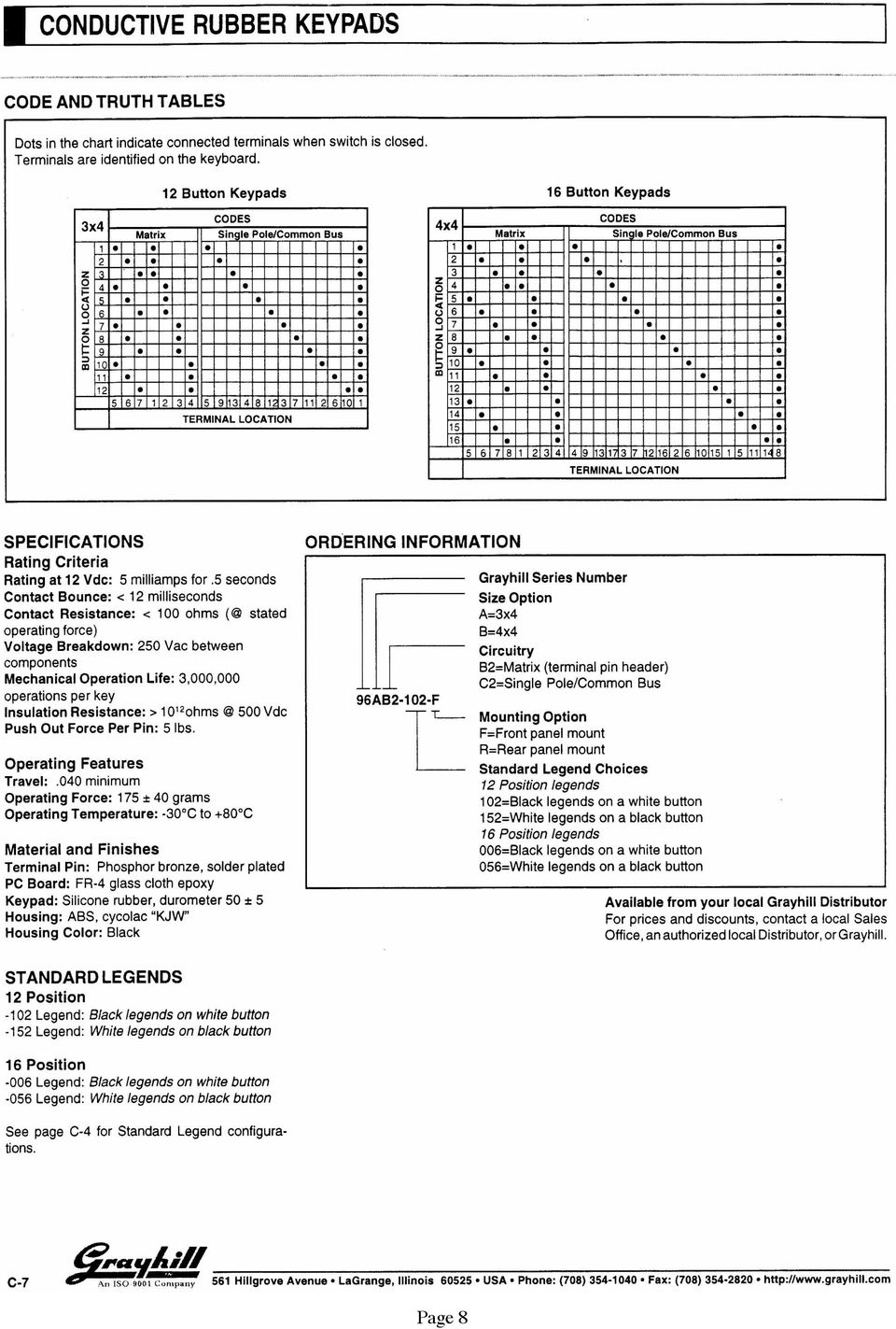
4 Part 3: Interfacing a Keypad to the 8051 GOAL By doing this lab assignment, you will learn to: 1. Interface the C8051F120 to a Grayhill 16-button keypad. 2. Develop interrupt-activated software to decode key presses on the keypad. PREPARATION References: C8051F12x-13x Reference Manual, Ch. 13, 14, 23, 24 Write a header file, called keypad.h that has the interrupt initialization routine and Interrupt Service Routine. Develop a new version of your code from Part 2 that incorporates the header file and uses the keypad for all user input. Write a flow chart for the operation of the Interrupt Service Routine. Create a circuit schematic to handle the interrupt generation INTRODUCTION TO THE KEYPAD Programming Tasks This part of the lab adds a keypad to the program that was developed in Part 2. The keypad is connected to the microcontroller by the External Interrupt 0. This will allow the keypad to operate on an interruptbased method. The code for controlling the keypad will be located in a header file called keypad.h. This will allow the file to be easily transported to different programs. The Grayhill keypad is an industry standard device that was designed to work with another standardized microcontroller port with a built-in hardware interrupt capability called a Key Wakeup. For historical perspective, each bit of the port supporting Key Wakeup can be used to generate a Key Wakeup interrupt when either a rising or falling edge is detected. It is important to note that even though each bit can generate an interrupt independently of the others, the same interrupt will be called regardless of which bit triggered it. The Key Wakeup Interrupt for each individual bit is enabled using a SFR. Writing a 1 to a bit in the register will enable the corresponding bit of the port to generate an interrupt when a falling edge is detected. The flag bits for the Key Wakeup interrupt are located in another SFR. Multiple flags can be set at the same time, although software must be written in order to determine which flags have been set. The flags are cleared by writing a one to the flag bits that have been set. It is a good idea to clear the flags before the Key Wakeup Interrupt is enabled to prevent any false triggers. Unfortunately the C8051 does not support this standard hardware interface. To implement the same functionality, an extra logic device must be added to the hardware to permit keypad hits to generate interrupts. The ANDing of the keypad input lines (4 LSBits) creates a suitable signal for generating interrupts when connected to INT0. You may want to consider using a keypad for your final project. One idea for this would be, instead of returning the value to the main program, to have the buttons call different functions, which in effect allows the keypad to operate as a more advanced flexible version of the IRQ. Page 4

5 Required Additional Hardware Add four 10kΩ pull-up resistors on P3.3-0 to the +3.3V supply. An ANDing operation of the four bits P3.3-0 will be used to generate an INT0 interrupt. A 4-input AND gate is made from 3 2-input 7408 DIP AND gates available in the lab. Required Software Setup Port 3 pins P3.3-0 must be configured as inputs: Open-drain option on P3MDOUT and set data values to 1 s (P3 = 0x0F). Interrupt INT0 is used to detect a key press on the keypad. The key decode subroutine must be assigned to INT0. The interrupt works better when set for level triggering rather than edge triggering. The keypad switches are noisy so delays must be added to wait for the signals to settle. Delays must also be used when switching the outputs on and off to allow the slow signals to settle. It will be necessary to use the xdata keyword on many variables to move them to external memory where there is more room. Helpful Hints 1. You should use port P3 for the keypad. 2. Remember to assign the ISR vector to INT0 used for the Key Wakeup with: void KeypadVector(void) interrupt 0 3. Remember to clear the flag for INT0 triggered by the keypad hardware. 4. You must include C8051F120.h in the header file. If you do not include this then the compiler will not recognize any of the register names for the F120 SFRs. You must include putget.h, or LCD.c & LCD.h if you want to use any of those I/O functions. 5. Be sure to add the external 10kΩ pull-ups and configure the output pins as push-pull & the input pins as open-drain. The keypad may work (intermittently) without the pull-up resistors. In general, the rise & fall times of the voltage pulses on the data line are a little slow and the pull-ups improve the signals at the expense of increasing the current draw and power requirements of the system. See the sample code below. 6. Remember the column select bit values are 1,2,4,8 not 1,2,3,4. KEYPAD INITIALIZATION FRAGMENT Use SYSCLK set to MHz from the external crystal and the following: P3MDOUT=0xF0; P3=0x0F; TCON=TCON & 0xFC; IE=IE 0x81; // hi nibble to push-pull, lo nibble to open-drain // write 0's to Port 3 hi nibble, lo nibble set for input // Clear INT0 flag and set for level triggered // Enable all interrupts & enable INT0 Page 5

6 KEYPAD DECODING FRAGMENT Once an interrupt has been detected, reading P3 will indicate which column the pressed key is in. Switching the 4 outputs on one at a time will determine which row contains the pressed key and the combination of the row and column will determine the precise key that was pressed. Global variables are necessary to pass values from ISRs back to the main program. Here asciichar is declared to be global. P3=0x8F; for(i = 0; i<300; i++); // check if row one (top) was active // wait for the output and input pins to stabilize portvalue = P3 & 0x0F; if (portvalue == 0x0F) { if (keyvalue == 0x07) asciichar = 1 ; else if (keyvalue == 0x0B) asciichar = 2 ; else if (keyvalue == 0x0D) asciichar = 3 ; else asciichar = A ; } else... // read the value of the lower 4 bits // if this row was selected then the value will be 0x0F // since the 1 on bit 7 will allow the 4 inputs to be hi // look at the value of the low 4 bits // return the value of the matching key // must be another row Before returning from the interrupt routine, make sure the key has been released and then delay a little before re-enabling interrupts to prevent any stray bounces from retriggering the interrupt. while (P3!= 0x0F); // wait while the key is still pressed for(i = 0; i<10000; i++);// wait for output and input pins to stabilize // after key is released IE = IE 0x81; // enable INT0 interrupt Page 6
; // check if row one (top) was active // wait for the output and input pins to stabilize portvalue = P3 & 0x0F; if (portvalue == 0x0F) { if (keyvalue == 0x07)")
7 Keypad wiring diagram - The keypad is a passive device with only switches that connect wires on the crossbar matrix of 4 x 4 wires. Page 7

8 Page 8
Keil C51 Cross Compiler
 Keil C51 Cross Compiler ANSI C Compiler Generates fast compact code for the 8051 and it s derivatives Advantages of C over Assembler Do not need to know the microcontroller instruction set Register allocation
8051 MICROCONTROLLER COURSE
 8051 MICROCONTROLLER COURSE Objective: 1. Familiarization with different types of Microcontroller 2. To know 8051 microcontroller in detail 3. Programming and Interfacing 8051 microcontroller Prerequisites:
PC Base Adapter Daughter Card UART GPIO. Figure 1. ToolStick Development Platform Block Diagram
 TOOLSTICK VIRTUAL TOOLS USER S GUIDE RELEVANT DEVICES 1. Introduction The ToolStick development platform consists of a ToolStick Base Adapter and a ToolStick Daughter card. The ToolStick Virtual Tools
CHAPTER 11: Flip Flops
 CHAPTER 11: Flip Flops In this chapter, you will be building the part of the circuit that controls the command sequencing. The required circuit must operate the counter and the memory chip. When the teach
Serial Communications
 Serial Communications 1 Serial Communication Introduction Serial communication buses Asynchronous and synchronous communication UART block diagram UART clock requirements Programming the UARTs Operation
Microcontroller Based Low Cost Portable PC Mouse and Keyboard Tester
 Leonardo Journal of Sciences ISSN 1583-0233 Issue 20, January-June 2012 p. 31-36 Microcontroller Based Low Cost Portable PC Mouse and Keyboard Tester Ganesh Sunil NHIVEKAR *, and Ravidra Ramchandra MUDHOLKAR
ENGI E1112 Departmental Project Report: Computer Science/Computer Engineering
 ENGI E1112 Departmental Project Report: Computer Science/Computer Engineering Daniel Estrada Taylor, Dev Harrington, Sekou Harris December 2012 Abstract This document is the final report for ENGI E1112,
Data Acquisition Module with I2C interface «I2C-FLEXEL» User s Guide
 Data Acquisition Module with I2C interface «I2C-FLEXEL» User s Guide Sensors LCD Real Time Clock/ Calendar DC Motors Buzzer LED dimming Relay control I2C-FLEXEL PS2 Keyboards Servo Motors IR Remote Control
Lab #5: Design Example: Keypad Scanner and Encoder - Part 1 (120 pts)
") Dr. Greg Tumbush, gtumbush@uccs.edu Lab #5: Design Example: Keypad Scanner and Encoder - Part 1 (120 pts) Objective The objective of lab assignments 5 through 9 are to systematically design and implement
Dr. Greg Tumbush, gtumbush@uccs.edu Lab #5: Design Example: Keypad Scanner and Encoder - Part 1 (120 pts) Objective The objective of lab assignments 5 through 9 are to systematically design and implement
ETEC 421 - Digital Controls PIC Lab 10 Pulse Width Modulation
 ETEC 421 - Digital Controls PIC Lab 10 Pulse Width Modulation Program Definition: Write a program to control the speed of a dc motor using pulse width modulation. Discussion: The speed of a dc motor is
AVR151: Setup and Use of the SPI. Introduction. Features. Atmel AVR 8-bit Microcontroller APPLICATION NOTE
 Atmel AVR 8-bit Microcontroller AVR151: Setup and Use of the SPI APPLICATION NOTE Introduction This application note describes how to set up and use the on-chip Serial Peripheral Interface (SPI) of the
How to design and implement firmware for embedded systems
 How to design and implement firmware for embedded systems Last changes: 17.06.2010 Author: Rico Möckel The very beginning: What should I avoid when implementing firmware for embedded systems? Writing code
C8051F020 Utilization in an Embedded Digital Design Project Course. Daren R. Wilcox Southern Polytechnic State University Marietta, Georgia
 C8051F020 Utilization in an Embedded Digital Design Project Course Daren R. Wilcox Southern Polytechnic State University Marietta, Georgia Abstract In this paper, the utilization of the C8051F020 in an
HANDLING SUSPEND MODE ON A USB MOUSE
 APPLICATION NOTE HANDLING SUSPEND MODE ON A USB MOUSE by Microcontroller Division Application Team INTRODUCTION All USB devices must support Suspend mode. Suspend mode enables the devices to enter low-power
Develop a Dallas 1-Wire Master Using the Z8F1680 Series of MCUs
 Develop a Dallas 1-Wire Master Using the Z8F1680 Series of MCUs AN033101-0412 Abstract This describes how to interface the Dallas 1-Wire bus with Zilog s Z8F1680 Series of MCUs as master devices. The Z8F0880,
LCD I 2 C/Serial RX Backpack. Data Sheet. LCD to I2C/Serial RX Backpack I2C or Serial RX communication with Standard 16 Pin LCD modules
 LCD I 2 C/Serial RX Backpack Data Sheet LCD to I2C/Serial RX Backpack I2C or Serial RX communication with Standard 16 Pin LCD modules Version 203 Sep 2013 Contents Contents 2 Introduction3 Voltage Levels3
AN141 SMBUS COMMUNICATION FOR SMALL FORM FACTOR DEVICE FAMILIES. 1. Introduction. 2. Overview of the SMBus Specification. 2.1.
 SMBUS COMMUNICATION FOR SMALL FORM FACTOR DEVICE FAMILIES 1. Introduction C8051F3xx and C8051F41x devices are equipped with an SMBus serial I/O peripheral that is compliant with both the System Management
Microcontroller Code Example Explanation and Words of Wisdom For Senior Design
 Microcontroller Code Example Explanation and Words of Wisdom For Senior Design For use with the following equipment: PIC16F877 QikStart Development Board ICD2 Debugger MPLAB Environment examplemain.c and
Controlling a Dot Matrix LED Display with a Microcontroller
 Controlling a Dot Matrix LED Display with a Microcontroller By Matt Stabile and programming will be explained in general terms as well to allow for adaptation to any comparable microcontroller or LED matrix.
RS-485 Protocol Manual
 RS-485 Protocol Manual Revision: 1.0 January 11, 2000 RS-485 Protocol Guidelines and Description Page i Table of Contents 1.0 COMMUNICATIONS BUS OVERVIEW... 1 2.0 DESIGN GUIDELINES... 1 2.1 Hardware Design
Table 1 below is a complete list of MPTH commands with descriptions. Table 1 : MPTH Commands. Command Name Code Setting Value Description
 MPTH: Commands Table 1 below is a complete list of MPTH commands with descriptions. Note: Commands are three bytes long, Command Start Byte (default is 128), Command Code, Setting value. Table 1 : MPTH
DEPARTMENT OF COMPUTER SCIENCE & ENGINEERING Question Bank Subject Name: EC6504 - Microprocessor & Microcontroller Year/Sem : II/IV
 DEPARTMENT OF COMPUTER SCIENCE & ENGINEERING Question Bank Subject Name: EC6504 - Microprocessor & Microcontroller Year/Sem : II/IV UNIT I THE 8086 MICROPROCESSOR 1. What is the purpose of segment registers
Lab 6 Introduction to Serial and Wireless Communication
 University of Pennsylvania Department of Electrical and Systems Engineering ESE 111 Intro to Elec/Comp/Sys Engineering Lab 6 Introduction to Serial and Wireless Communication Introduction: Up to this point,
Computer Organization and Components
 Computer Organization and Components IS1500, fall 2015 Lecture 5: I/O Systems, part I Associate Professor, KTH Royal Institute of Technology Assistant Research Engineer, University of California, Berkeley
Using the Siemens S65 Display
 Using the Siemens S65 Display by Christian Kranz, October 2005 ( http://www.superkranz.de/christian/s65_display/displayindex.html ) ( PDF by Benjamin Metz, 01 st November 2005 ) About the Display: Siemens
150127-Microprocessor & Assembly Language
 Chapter 3 Z80 Microprocessor Architecture The Z 80 is one of the most talented 8 bit microprocessors, and many microprocessor-based systems are designed around the Z80. The Z80 microprocessor needs an
SKP16C62P Tutorial 1 Software Development Process using HEW. Renesas Technology America Inc.
 SKP16C62P Tutorial 1 Software Development Process using HEW Renesas Technology America Inc. 1 Overview The following tutorial is a brief introduction on how to develop and debug programs using HEW (Highperformance
Interface and Simulation of a LCD Text Display
 OVERVIEW The following application note describes the interface of a LCD text display to a 8051 microcontroller system. This application note comes with the µvision2 project LCD_Display.UV2 that includes
Hardware and Software Requirements
 C Compiler Real-Time OS Simulator Training Evaluation Boards Installing and Using the Keil Monitor-51 Application Note 152 May 31, 2000, Munich, Germany by Keil Support, Keil Elektronik GmbH support.intl@keil.com
Accurate Measurement of the Mains Electricity Frequency
 Accurate Measurement of the Mains Electricity Frequency Dogan Ibrahim Near East University, Faculty of Engineering, Lefkosa, TRNC dogan@neu.edu.tr Abstract The frequency of the mains electricity supply
Serial Communications
 April 2014 7 Serial Communications Objectives - To be familiar with the USART (RS-232) protocol. - To be able to transfer data from PIC-PC, PC-PIC and PIC-PIC. - To test serial communications with virtual
Comparing RTOS to Infinite Loop Designs
 Comparing RTOS to Infinite Loop Designs If you compare the way software is developed for a small to medium sized embedded project using a Real Time Operating System (RTOS) versus a traditional infinite
AVR Butterfly Training. Atmel Norway, AVR Applications Group
 AVR Butterfly Training Atmel Norway, AVR Applications Group 1 Table of Contents INTRODUCTION...3 GETTING STARTED...4 REQUIRED SOFTWARE AND HARDWARE...4 SETTING UP THE HARDWARE...4 SETTING UP THE SOFTWARE...5
AUTOMATIC NIGHT LAMP WITH MORNING ALARM USING MICROPROCESSOR
 AUTOMATIC NIGHT LAMP WITH MORNING ALARM USING MICROPROCESSOR INTRODUCTION This Project "Automatic Night Lamp with Morning Alarm" was developed using Microprocessor. It is the Heart of the system. The sensors
STEPPER MOTOR SPEED AND POSITION CONTROL
 STEPPER MOTOR SPEED AND POSITION CONTROL Group 8: Subash Anigandla Hemanth Rachakonda Bala Subramanyam Yannam Sri Divya Krovvidi Instructor: Dr. Jens - Peter Kaps ECE 511 Microprocessors Fall Semester
Hello, and welcome to this presentation of the STM32L4 reset and clock controller.
 Hello, and welcome to this presentation of the STM32L4 reset and clock controller. 1 The STM32L4 reset and clock controller manages system and peripheral clocks. STM32L4 devices embed three internal oscillators,
PIC Programming in Assembly. (http://www.mstracey.btinternet.co.uk/index.htm)
") PIC Programming in Assembly (http://www.mstracey.btinternet.co.uk/index.htm) Tutorial 1 Good Programming Techniques. Before we get to the nitty gritty of programming the PIC, I think now is a good time
PIC Programming in Assembly (http://www.mstracey.btinternet.co.uk/index.htm) Tutorial 1 Good Programming Techniques. Before we get to the nitty gritty of programming the PIC, I think now is a good time
HD44780U (LCD-II) (Dot Matrix Liquid Crystal Display Controller/Driver)
 (Dot Matrix Liquid Crystal Display Controller/Driver)") HD4478U (LCD-II) (Dot Matrix Liquid Crystal Display Controller/Driver) Description The HD4478U dot-matrix liquid crystal display controller and driver LSI displays alphanumerics, Japanese kana characters,
HD4478U (LCD-II) (Dot Matrix Liquid Crystal Display Controller/Driver) Description The HD4478U dot-matrix liquid crystal display controller and driver LSI displays alphanumerics, Japanese kana characters,
AN3252 Application note
 Application note Building a wave generator using STM8L-DISCOVERY Application overview This application note provides a short description of how to use the STM8L-DISCOVERY as a basic wave generator for
USB2.0 <=> I2C V4.4. Konverter Kabel und Box mit Galvanischetrennung
 USB2.0 I2C V4.4 Konverter Kabel und Box mit Galvanischetrennung USB 2.0 I2C Konverter Kabel V4.4 (Prod. Nr. #210) USB Modul: Nach USB Spezifikation 2.0 & 1.1 Unterstützt automatisch "handshake
Designing VM2 Application Boards
 Designing VM2 Application Boards This document lists some things to consider when designing a custom application board for the VM2 embedded controller. It is intended to complement the VM2 Datasheet. A
8-bit Microcontroller. Application Note. AVR415: RC5 IR Remote Control Transmitter. Features. Introduction. Figure 1.
 AVR415: RC5 IR Remote Control Transmitter Features Utilizes ATtiny28 Special HW Modulator and High Current Drive Pin Size Efficient Code, Leaves Room for Large User Code Low Power Consumption through Intensive
Data Cables. Schmitt TTL LABORATORY ELECTRONICS II
 Data Cables Data cables link one instrument to another. Signals can attenuate or disperse on long wires. A direct wire works best for short cables of less than 10 ft. A TTL cable connection can use a Schmitt
Troubleshooting and Diagnostics
 Troubleshooting and Diagnostics The troubleshooting and diagnostics guide provides instructions to assist in tracking down the source of many basic controller installation problems. If there is a problem
20 Using Scripts. (Programming without Parts) 20-1
 20-1") 20 Using Scripts (Programming without Parts) This chapter explains the basics of creating and using programming scripts in GP-Pro EX. Please start by reading 20.1 Settings Menu (page 20-2) and then turn
20 Using Scripts (Programming without Parts) This chapter explains the basics of creating and using programming scripts in GP-Pro EX. Please start by reading 20.1 Settings Menu (page 20-2) and then turn
Jianjian Song LogicWorks 4 Tutorials (5/15/03) Page 1 of 14
 Page 1 of 14") LogicWorks 4 Tutorials Jianjian Song Department of Electrical and Computer Engineering Rose-Hulman Institute of Technology March 23 Table of Contents LogicWorks 4 Installation and update...2 2 Tutorial
LogicWorks 4 Tutorials Jianjian Song Department of Electrical and Computer Engineering Rose-Hulman Institute of Technology March 23 Table of Contents LogicWorks 4 Installation and update...2 2 Tutorial
ARM Thumb Microcontrollers. Application Note. Software ISO 7816 I/O Line Implementation. Features. Introduction
 Software ISO 7816 I/O Line Implementation Features ISO 7816-3 compliant (direct convention) Byte reception and transmission with parity check Retransmission on error detection Automatic reception at the
Programing the Microprocessor in C Microprocessor System Design and Interfacing ECE 362
 PURDUE UNIVERSITY Programing the Microprocessor in C Microprocessor System Design and Interfacing ECE 362 Course Staff 1/31/2012 1 Introduction This tutorial is made to help the student use C language
PRODUCTIVITY THROUGH INNOVATION 600 CONTROL DIRECT DRIVE TECHNICAL/OPERATION MANUAL
 Rev. D PRODUCTIVITY THROUGH INNOVATION 600 CONTROL DIRECT DRIVE TECHNICAL/OPERATION MANUAL 10 BORIGHT AVENUE, KENILWORTH NEW JERSEY 07033 TELEPHONE: 800-524-0273 FAX: 908-686-9317 TABLE OF CONTENTS Page
ENGG*44200 Real Time System Design Lab3 Implement VoIP on ARM Outline
 ENGG*44200 Real Time System Design Lab3 Implement VoIP on ARM 1 Outline Features of VoIP IP Communication Device Examples Phone Protocol of the Lab 2 VoIP Voice Calls are transmitted over Packet Switched
Microcontroller Systems. ELET 3232 Topic 8: Slot Machine Example
 Microcontroller Systems ELET 3232 Topic 8: Slot Machine Example 1 Agenda We will work through a complete example Use CodeVision and AVR Studio Discuss a few creative instructions Discuss #define and #include
RS232 Board datasheet
 RS232 Board datasheet Contents 1. About this document 2. General information 3. Board Layout 4. Getting Started 5. Circuit Description Appendix 1 Circuit Diagram Copyright 2004 Matrix Multimedia Limited
Application Unit, MDRC AB/S 1.1, GH Q631 0030 R0111
 , GH Q631 0030 R0111 SK 0010 B 98 The application unit is a DIN rail mounted device for insertion in the distribution board. The connection to the EIB is established via a bus connecting terminal at the
Design and Implementation of Home Monitoring System Using RF Technology
 International Journal of Advances in Electrical and Electronics Engineering 59 Available online at www.ijaeee.com & www.sestindia.org/volume-ijaeee/ ISSN: 2319-1112 Design and Implementation of Home Monitoring
Lab Experiment 1: The LPC 2148 Education Board
 Lab Experiment 1: The LPC 2148 Education Board 1 Introduction The aim of this course ECE 425L is to help you understand and utilize the functionalities of ARM7TDMI LPC2148 microcontroller. To do that,
An Introduction to MPLAB Integrated Development Environment
 An Introduction to MPLAB Integrated Development Environment 2004 Microchip Technology Incorporated An introduction to MPLAB Integrated Development Environment Slide 1 This seminar is an introduction to
Technical Note. Micron NAND Flash Controller via Xilinx Spartan -3 FPGA. Overview. TN-29-06: NAND Flash Controller on Spartan-3 Overview
 Technical Note TN-29-06: NAND Flash Controller on Spartan-3 Overview Micron NAND Flash Controller via Xilinx Spartan -3 FPGA Overview As mobile product capabilities continue to expand, so does the demand
How To Program A Microcontroller Board (Eb064) With A Psp Microcontroller (B064-74) With An Ios 2.5V (Power) And A Ppt (Power Control) (Power Supply) (
 With A Psp Microcontroller (B064-74) With An Ios 2.5V (Power) And A Ppt (Power Control) (Power Supply) (") dspic / PIC24 Multiprogrammer datasheet EB064-00 00-1 Contents 1. About this document... 2 2. General information... 3 3. Board layout... 4 4. Testing this product... 5 5. Circuit description... 6 Appendix
dspic / PIC24 Multiprogrammer datasheet EB064-00 00-1 Contents 1. About this document... 2 2. General information... 3 3. Board layout... 4 4. Testing this product... 5 5. Circuit description... 6 Appendix
USBSPYDER08 Discovery Kit for Freescale MC9RS08KA, MC9S08QD and MC9S08QG Microcontrollers User s Manual
 USBSPYDER08 Discovery Kit for Freescale MC9RS08KA, MC9S08QD and MC9S08QG Microcontrollers User s Manual Copyright 2007 SofTec Microsystems DC01197 We want your feedback! SofTec Microsystems is always on
Freescale Semiconductor, I
 nc. Application Note 6/2002 8-Bit Software Development Kit By Jiri Ryba Introduction 8-Bit SDK Overview This application note describes the features and advantages of the 8-bit SDK (software development
Embedded Systems Design Course Applying the mbed microcontroller
 Embedded Systems Design Course Applying the mbed microcontroller Serial communications with SPI These course notes are written by R.Toulson (Anglia Ruskin University) and T.Wilmshurst (University of Derby).
8 by 8 dot matrix LED displays with Cascadable Serial driver B32CDM8 B48CDM8 B64CDM8 General Description
 8 by 8 dot matrix LED displays with Cascadable Serial driver B32CDM8 B48CDM8 B64CDM8 General Description The B32CDM8, B48CDM8 and the B64CDM8 are 8 by 8 (row by column) dot matrix LED displays combined
Decimal Number (base 10) Binary Number (base 2)
 Binary Number (base 2)") LECTURE 5. BINARY COUNTER Before starting with counters there is some vital information that needs to be understood. The most important is the fact that since the outputs of a digital chip can only be
LECTURE 5. BINARY COUNTER Before starting with counters there is some vital information that needs to be understood. The most important is the fact that since the outputs of a digital chip can only be
WA Manager Alarming System Management Software Windows 98, NT, XP, 2000 User Guide
 WA Manager Alarming System Management Software Windows 98, NT, XP, 2000 User Guide Version 2.1, 4/2010 Disclaimer While every effort has been made to ensure that the information in this guide is accurate
PART B QUESTIONS AND ANSWERS UNIT I
 PART B QUESTIONS AND ANSWERS UNIT I 1. Explain the architecture of 8085 microprocessor? Logic pin out of 8085 microprocessor Address bus: unidirectional bus, used as high order bus Data bus: bi-directional
Wiki Lab Book. This week is practice for wiki usage during the project.
 Wiki Lab Book Use a wiki as a lab book. Wikis are excellent tools for collaborative work (i.e. where you need to efficiently share lots of information and files with multiple people). This week is practice
DS1821 Programmable Digital Thermostat and Thermometer
 ma www.maxim-ic.com FEATURES Requires no external components Unique 1-Wire interface requires only one port pin for communication Operates over a -55 C to +125 C (67 F to +257 F) temperature range Functions
Switch board datasheet EB007-00-1
 Switch board datasheet EB007-00-1 Contents 1. About this document... 2 2. General information... 3 3. Board layout... 4 4. Testing this product... 5 5. Circuit description... 6 Appendix 1 Circuit diagram
The stack and the stack pointer
 The stack and the stack pointer If you google the word stack, one of the definitions you will get is: A reserved area of memory used to keep track of a program's internal operations, including functions,
Teaching Systems Integration In An Advanced Microprocessor Applications Course
 Teaching Systems Integration In An Advanced Microprocessor Applications Course Phil Fabiano New Jersey Institute of Technology University Heights Newark, New Jersey 07102 Abstract The New Jersey Institute
Embedded Programming in C/C++: Lesson-1: Programming Elements and Programming in C
 Embedded Programming in C/C++: Lesson-1: Programming Elements and Programming in C 1 An essential part of any embedded system design Programming 2 Programming in Assembly or HLL Processor and memory-sensitive
TO HANDPHONE BURGLAR ALARM USING PIC 16F877A MICROCONTROLLER
 KULLIYYAH OF ENGINEERING INTERNATIONAL ISLAMIC UNIVERSITY MALAYSIA TO HANDPHONE BURGLAR ALARM USING PIC 16F877A MICROCONTROLLER ABDUL HASSAN B JAAFAR 0615723 ENGINEERING INDUSTRIAL TRAINING AT TELEKOM
AN601 I2C 2.8 Communication Protocol. SM130 SM130 - Mini APPLICATION NOTE
 AN601 I2C 2.8 Communication Protocol SM130 SM130 - Mini APPLICATION NOTE 2 1. INTRODUCTION This application note explains I2C communication protocol with SM130 or SM130-Mini Mifare module based on the
UNIT 4 Software Development Flow
 DESIGN OF SYSTEM ON CHIP UNIT 4 Software Development Flow Interrupts OFFICIAL MASTER IN ADVANCED ELECTRONIC SYSTEMS. INTELLIGENT SYSTEMS Outline Introduction Interrupts in Cortex-A9 Processor Interrupt
[F/T] [5] [KHz] [AMP] [3] [V] 4 ) To set DC offset to -2.5V press the following keys [OFS] [+/-] [2] [.] [5] [V]
![[F/T] [5] [KHz] [AMP] [3] [V] 4 ) To set DC offset to -2.5V press the following keys [OFS] [+/-] [2] [.] [5] [V]](/thumbs/40/20623504.jpg "[F/T] [5] [KHz] [AMP] [3] [V] 4 ) To set DC offset to -2.5V press the following keys [OFS] [+/-] [2] [.] [5] [V]") FG085 minidds Function Generator Manual of Operation Applicable Models: 08501, 08501K, 08502K, 08503, 08503K Applicable Firmware Version: 1 ) 113-08501-100 or later (for U5) 2 ) 113-08502-030 or later
FG085 minidds Function Generator Manual of Operation Applicable Models: 08501, 08501K, 08502K, 08503, 08503K Applicable Firmware Version: 1 ) 113-08501-100 or later (for U5) 2 ) 113-08502-030 or later
EXERCISE 3: String Variables and ASCII Code
 EXERCISE 3: String Variables and ASCII Code EXERCISE OBJECTIVE When you have completed this exercise, you will be able to describe the use of string variable and ASCII code. You will use Flowcode and the
User Manual. AS-Interface Programmer
 AS-Interface Programmer Notice: RESTRICTIONS THE ZMD AS-INTERFACE PROGRAMMER HARDWARE AND ZMD AS-INTERFACE PROGRAMMER SOFTWARE IS DESIGNED FOR IC EVALUATION, LABORATORY SETUP AND MODULE DEVELOPMENT ONLY.
Scan a Keypad with the BS2 For Pushbutton User Input
 Stamp Applications no. 22 (December 96): Scan a Keypad with the BS2 For Pushbutton User Input 16-key matrix keypad software plus beginner s race-timer project by Scott Edwards THE BUTTON instruction offered
Special Lecture. Basic Stamp 2 Programming. (Presented on popular demand)
") Special Lecture Basic Stamp 2 Programming (Presented on popular demand) Programming Environment Servo Motor: How It Work? The editor window consists of the main edit pane with an integrated explorer panel
Special Lecture Basic Stamp 2 Programming (Presented on popular demand) Programming Environment Servo Motor: How It Work? The editor window consists of the main edit pane with an integrated explorer panel
Debouncing Switches. Mechanical switches are one of the most common interfaces to a uc.
 Mechanical switches are one of the most common interfaces to a uc. Switch inputs are asynchronous to the uc and are not electrically clean. Asynchronous inputs can be handled with a synchronizer (2 FF's).
AN111: Using 8-Bit MCUs in 5 Volt Systems
 This document describes how to incorporate Silicon Lab s 8-bit EFM8 and C8051 families of devices into existing 5 V systems. When using a 3 V device in a 5 V system, the user must consider: A 3 V power
TURBO PROGRAMMER USB, MMC, SIM DEVELOPMENT KIT
 TURBO PROGRAMMER USB, MMC, SIM DEVELOPMENT KIT HARDWARE GUIDE This document is part of Turbo Programmer documentation. For Developer Documentation, Applications and Examples, see http:/// PRELIMINARY (C)
M68EVB908QL4 Development Board for Motorola MC68HC908QL4
 M68EVB908QL4 Development Board for Motorola MC68HC908QL4! Axiom Manufacturing 2813 Industrial Lane Garland, TX 75041 Email: Sales@axman.com Web: http://www.axman.com! CONTENTS CAUTIONARY NOTES...3 TERMINOLOGY...3
Lab 17: Building a 4-Digit 7-Segment LED Decoder
 Phys2303 L.A. Bumm [Nexys 1.1.2] Lab 17 (p1) Lab 17: Building a 4-Digit 7-Segment LED Decoder In this lab your will make 4 test circuits, the 4-digit 7-segment decoder, and demonstration circuit using
Measuring Resistance Using Digital I/O
 Measuring Resistance Using Digital I/O Using a Microcontroller for Measuring Resistance Without using an ADC. Copyright 2011 John Main http://www.best-microcontroller-projects.com Page 1 of 10 Table of
POCKET SCOPE 2. The idea 2. Design criteria 3
 POCKET SCOPE 2 The idea 2 Design criteria 3 Microcontroller requirements 3 The microcontroller must have speed. 3 The microcontroller must have RAM. 3 The microcontroller must have secure Flash. 3 The
Animated Lighting Software Overview
 Animated Lighting Software Revision 1.0 August 29, 2003 Table of Contents SOFTWARE OVERVIEW 1) Dasher Pro and Animation Director overviews 2) Installing the software 3) Help 4) Configuring the software
8-Bit Microcontroller with Flash. Application Note. Using a Personal Computer to Program the AT89C51/C52/LV51/LV52/C1051/C2051
 Using a Personal Computer to Program the ATC/C/LV/LV/C0/C0 Introduction This application note describes a personal computer-based programmer for the ATC/C/LV/LV/C0/C0 Flash-based s. The programmer supports
The Secrets of RS-485 Half-duplex Communication
 Communication Casper Yang, Senior Product Manager support@moxa.com RS-485 is a good choice for long distance serial communication since using differential transmission cancels out the vast majority of
DS1307ZN. 64 x 8 Serial Real-Time Clock
 DS137 64 x 8 Serial Real-Time Clock www.maxim-ic.com FEATURES Real-time clock (RTC) counts seconds, minutes, hours, date of the month, month, day of the week, and year with leap-year compensation valid
AN3265 Application note
 Application note Handling hardware and software failures with the STM8S-DISCOVERY Application overview This application is based on the STM8S-DISCOVERY. It demonstrates how to use the STM8S window watchdog
Display Board Pulse Width Modulation (PWM) Power/Speed Controller Module
 Power/Speed Controller Module") Display Board Pulse Width Modulation (PWM) Power/Speed Controller Module RS0 Microcontroller LEDs Motor Control Pushbuttons Purpose: To demonstrate an easy way of using a Freescale RS0K2 microcontroller
Display Board Pulse Width Modulation (PWM) Power/Speed Controller Module RS0 Microcontroller LEDs Motor Control Pushbuttons Purpose: To demonstrate an easy way of using a Freescale RS0K2 microcontroller
Parallax Serial LCD 2 rows x 16 characters Non-backlit (#27976) 2 rows x 16 characters Backlit (#27977) 4 rows x 20 characters Backlit (#27979)
 2 rows x 16 characters Backlit (#27977) 4 rows x 20 characters Backlit (#27979)") 599 Menlo Drive, Suite 100 Rocklin, California 95765, USA Office: (916) 624-8333 Fax: (916) 624-8003 General: info@parallax.com Technical: support@parallax.com Web Site: www.parallax.com Educational: www.stampsinclass.com
599 Menlo Drive, Suite 100 Rocklin, California 95765, USA Office: (916) 624-8333 Fax: (916) 624-8003 General: info@parallax.com Technical: support@parallax.com Web Site: www.parallax.com Educational: www.stampsinclass.com
DS2401 Silicon Serial Number
 19-5860; Rev 3/15 Silicon Serial Number BENEFITS AND FEATURES Guaranteed Unique 64-Bit ROM ID Chip for Absolute Traceability o Unique, Factory-Lasered and Tested 64-Bit Registration Number (8-Bit Family
PHYS 2P32 Project: MIDI for Arduino/ 8 Note Keyboard
 PHYS 2P32 Project: MIDI for Arduino/ 8 Note Keyboard University April 13, 2016 About Arduino: The Board Variety of models of Arduino Board (I am using Arduino Uno) Microcontroller constructd similarly
Memory Systems. Static Random Access Memory (SRAM) Cell
 Cell") Memory Systems This chapter begins the discussion of memory systems from the implementation of a single bit. The architecture of memory chips is then constructed using arrays of bit implementations coupled
Memory Systems This chapter begins the discussion of memory systems from the implementation of a single bit. The architecture of memory chips is then constructed using arrays of bit implementations coupled
The components. E3: Digital electronics. Goals:
 E3: Digital electronics Goals: Basic understanding of logic circuits. Become familiar with the most common digital components and their use. Equipment: 1 st. LED bridge 1 st. 7-segment display. 2 st. IC
How To Use A Watt Saver On A Microcontroller (Watt Saver) On A Cell Phone Or Mp3 Player
 On A Cell Phone Or Mp3 Player") Watt Saver for a Cell Phone AC Adapter Reference Design Document Number: DRM130 Rev 1, 10/2013 2 Freescale Semiconductor, Inc. Contents Section number Title Page Chapter 1 Introduction 1.1 Overview...5
Watt Saver for a Cell Phone AC Adapter Reference Design Document Number: DRM130 Rev 1, 10/2013 2 Freescale Semiconductor, Inc. Contents Section number Title Page Chapter 1 Introduction 1.1 Overview...5
Using The PIC I/O Ports
 EE2801 -- Lecture 22 Using The PIC I/O Ports EE2801-L22P01 The Variety Of Available IO Ports The PIC 16F874 microcontroller has five different IO ports, accounting for thirty three of the processors forty
Windows CE 6.0 APEX ZF
 Windows CE 6.0 For APEX ZF User Guide Document Reference: Windows CE User Guide Document Issue: 1.0 Contents Introduction... 3 Windows CE 6.0 initialisation and booting overview... 3 APEX-ZF hardware evaluation