Time dependent circuits - The RC circuit
|
|
|
- Elwin Glenn
- 7 years ago
- Views:
Transcription
1 Time dependent circuits - The circuit Example 1 Charging a Capacitor- Up until now we have assumed that the emfs and resistances are constant in time, so that all potentials, currents and powers are constant in time. However, whenever we have a capacitor that is being charged, or discharged, this is not the case. Now, consider a circuit that consists of an emf, a resistor and a capacitor, but with an open switch With the switch open the current in the circuit is zero and zero charge accumulates on the capacitor

2 Time dependent circuits - The R-C circuit Example 1 Charging a Capacitor cont. Capacitor has no net charge at t=0 Voltage, current and charge are functions of time (we will use lower case letters to denote time-varying quantities). However Kirchhoff s Rules are still valid at any instant in Time
.")
3 + v ab = ir v bc = q C Ohms Law Definition of Capacitance q "! ir! = 0 Kirchhoff s Loop Rule C q i = " At t=0, there is no charge on! (hence no potential across) R the capacitor so at the instant the switch is closed, we expect Close Switch at t=0 a current of I 0 =ε/r (voltage drop is only across the resistor). As the capacitor charges, we expect the current to fall.

4 Charging a capacitor cont. i = "! R Charge will flow on the capacitor and the current will decrease until we reach i = 0, then: " R = Q f Q f = C" q Note, the final value charge, Q f does not depend on R So, we start with current I o =ε/r and the current reduced to! I f = 0, at the same time the charge on the capacitor increased from Q 0 =0 to Q f =Cε. But, what is the current or the charge on the capacitor at any instant in time?

5 i = "! R Charging a capacitor q dq dt = " R # q i = dq dt This is a differential equation. We can rearrange and integrate to find what! we need. This yields:! dq dt = " 1 q dq' $ = q'"c# 0 (q " C#) t $ 0 dt' $ ln q " C# ' & ) = " t % "C# (!

6 ! Charging a capacitor cont. $ ln q " C# ' & ) = " t % "C# ( Taking the exponents (inverse log) both sides: t q " C# "C# = e" Solving for q (now we re getting to the bit you need) Taking the time derivative, to get the instantaneous current, i!
 Taking the time")
7 Charging a capacitor instantaneous charge Remember: e= Q f -Q f /e

8 Charging a capacitor - instantaneous current i = I e "t / 0

9 R-C circuits - time constant After a time, the current in the R-C circuit has decreased to 1/e = of its initial value. At this time, the capacitor charge has reached (1-1/e) = of its final value Q f =Cε. The product is therefore a measure of how quickly the capacitor charges. We call the time constant (τ) of the circuit. " =

10 Discharging a capacitor Mr. Kirchhoff says (loop rule): + Now we start with a charged capacitor in series with an open switch (we have removed the battery from the earlier charging circuit). Now we close the switch and current will flow. We define time t=0 as the time we close the switch and q=q 0 at that time. We discharge the capacitor through the resistor fully until q=0 " # ir # q C = 0 but, there s no EMF, rearranging we get:! i = dq dt = " q

11 Discharging a capacitor - graphs i = dq dt = " q I 0 = " Q 0! Solving the same way as for charging (see Y&F p1000) we obtain! q = Q 0 e! t / I = I 0 e! t /
 we obtain! q = Q 0 e!")
12 Charging/discharging capacitors Which curve?
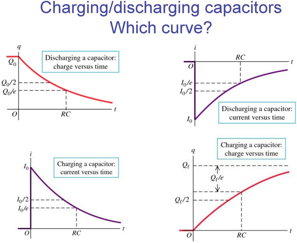
13 Charging/discharging capacitors Which curve? Strategy for understanding which curve is correct: Try to figure out what the current (or charge) would be just when the switch is closed (or opened) t = 0 Then try to figure out what the current (or charge) would be aftera very long time t =!
 t = 0 Then try to figure out what the current (or charge)")
14 Figuring out charging a capacitor At t=0 there is NO charge on the capacitor and therefore no voltage across capacitor I 0 =ε/r I 0 At t= the capacitor is fully charged and there is no current: I =0 I 0

15 Figuring out charging a capacitor At t=0 there is NO charge on the capacitor therefore Q 0 =0 At t= the capacitor is fully charged and therefore Q =Cε QI 0

16 Example: Ex from Y&F Before the switch is moved, the capacitor is uncharged: q 0 =0. Moving the switch to position 2 closes the circuit and the capacitor will charge. After a long time i.e. t >> the capacitor will be fully charged, no current flows and the voltage across the capacitor is equal to the emf. Q final = CV = (5.90 "10 #6 F)(28.0V ) Q final =1.65 "10 #4 C
(28.")
17 b) After the switch has been in position 2 for 3.00ms, the charge on the capacitor is measured to be 110µC. What is the value of the resistance R? q = Q f (1" e "t / ) # q Q f =1" e "t / # e "t / =1" q Q f Need R, so take ln of both sides "t = ln # % 1" q $ Q f R = t 1.1C & ( = ln # 1" 110 )10"6 C % ' $ 1.65 )10 "4 C 3.00 )10"3 = = 463* "6 1.1) 5.9 )10 & ( = "1.1 '
 # q Q f =1\" e \"t / # e \"t / =1\" q Q f Need R, so take ln of both sides")
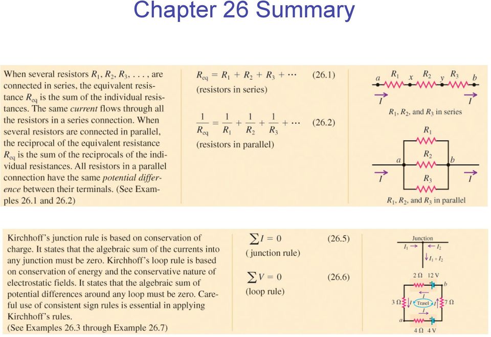
18 Chapter 26 Summary
19 Chapter 26 Summary cont.

20 End of Chapter 26 You are responsible for the material covered in Y&F Sections You are expected to: Understand the following terms: Equivalent Resistance, Junction, Kirchhoff junction rule, Kirchhoff s loop rule, R-C circuit, R-C time constant Be able to calculate equivalent resistances in simple geometries Be able to apply Kirchoff s rules to determine currents and voltages in more complex geometries Be able to determine the current and voltage as a function of time in R- C circuits. Recommended Y&F Exercises chapter 26: 19, 20, 21, 36, 39, 40, 43

Problem Solving 8: RC and LR Circuits
 MASSACHUSETTS INSTITUTE OF TECHNOLOGY Department of Physics Problem Solving 8: RC and LR Circuits Section Table and Group (e.g. L04 3C ) Names Hand in one copy per group at the end of the Friday Problem
= (0.400 A) (4.80 V) = 1.92 W = (0.400 A) (7.20 V) = 2.88 W
 (4.80 V) = 1.92 W = (0.400 A) (7.20 V) = 2.88 W") Physics 2220 Module 06 Homework 0. What are the magnitude and direction of the current in the 8 Ω resister in the figure? Assume the current is moving clockwise. Then use Kirchhoff's second rule: 3.00
Physics 2220 Module 06 Homework 0. What are the magnitude and direction of the current in the 8 Ω resister in the figure? Assume the current is moving clockwise. Then use Kirchhoff's second rule: 3.00
Circuits. The light bulbs in the circuits below are identical. Which configuration produces more light? (a) circuit I (b) circuit II (c) both the same
 circuit I (b) circuit II (c) both the same") Circuits The light bulbs in the circuits below are identical. Which configuration produces more light? (a) circuit I (b) circuit II (c) both the same Circuit II has ½ current of each branch of circuit
Circuits The light bulbs in the circuits below are identical. Which configuration produces more light? (a) circuit I (b) circuit II (c) both the same Circuit II has ½ current of each branch of circuit
CHAPTER 28 ELECTRIC CIRCUITS
 CHAPTER 8 ELECTRIC CIRCUITS 1. Sketch a circuit diagram for a circuit that includes a resistor R 1 connected to the positive terminal of a battery, a pair of parallel resistors R and R connected to the
Eðlisfræði 2, vor 2007
 [ Assignment View ] [ Print ] Eðlisfræði 2, vor 2007 30. Inductance Assignment is due at 2:00am on Wednesday, March 14, 2007 Credit for problems submitted late will decrease to 0% after the deadline has
Physics 2102 Lecture 19. Physics 2102
 Physics 2102 Jonathan Dowling Physics 2102 Lecture 19 Ch 30: Inductors and RL Circuits Nikolai Tesla What are we going to learn? A road map Electric charge Electric force on other electric charges Electric
Chapter 7 Direct-Current Circuits
 Chapter 7 Direct-Current Circuits 7. Introduction...7-7. Electromotive Force...7-3 7.3 Resistors in Series and in Parallel...7-5 7.4 Kirchhoff s Circuit Rules...7-7 7.5 Voltage-Current Measurements...7-9
The Time Constant of an RC Circuit
 The Time Constant of an RC Circuit 1 Objectives 1. To determine the time constant of an RC Circuit, and 2. To determine the capacitance of an unknown capacitor. 2 Introduction What the heck is a capacitor?
Chapter 7. DC Circuits
 Chapter 7 DC Circuits 7.1 Introduction... 7-3 Example 7.1.1: Junctions, branches and loops... 7-4 7.2 Electromotive Force... 7-5 7.3 Electrical Energy and Power... 7-9 7.4 Resistors in Series and in Parallel...
First Order Circuits. EENG223 Circuit Theory I
 First Order Circuits EENG223 Circuit Theory I First Order Circuits A first-order circuit can only contain one energy storage element (a capacitor or an inductor). The circuit will also contain resistance.
Current, Resistance and Electromotive Force. Young and Freedman Chapter 25
 Current, Resistance and Electromotive Force Young and Freedman Chapter 25 Electric Current: Analogy, water flowing in a pipe H 2 0 gallons/minute Flow Rate is the NET amount of water passing through a
Experiment #5, Series and Parallel Circuits, Kirchhoff s Laws
 Physics 182 Summer 2013 Experiment #5 1 Experiment #5, Series and Parallel Circuits, Kirchhoff s Laws 1 Purpose Our purpose is to explore and validate Kirchhoff s laws as a way to better understanding
AP Physics Electricity and Magnetism #4 Electrical Circuits, Kirchoff s Rules
 Name Period AP Physics Electricity and Magnetism #4 Electrical Circuits, Kirchoff s Rules Dr. Campbell 1. Four 240 Ω light bulbs are connected in series. What is the total resistance of the circuit? What
ES250: Electrical Science. HW7: Energy Storage Elements
 ES250: Electrical Science HW7: Energy Storage Elements Introduction This chapter introduces two more circuit elements, the capacitor and the inductor whose elements laws involve integration or differentiation;
Exercises on Voltage, Capacitance and Circuits. A d = (8.85 10 12 ) π(0.05)2 = 6.95 10 11 F
 π(0.05)2 = 6.95 10 11 F") Exercises on Voltage, Capacitance and Circuits Exercise 1.1 Instead of buying a capacitor, you decide to make one. Your capacitor consists of two circular metal plates, each with a radius of 5 cm. The
Exercises on Voltage, Capacitance and Circuits Exercise 1.1 Instead of buying a capacitor, you decide to make one. Your capacitor consists of two circular metal plates, each with a radius of 5 cm. The
W03 Analysis of DC Circuits. Yrd. Doç. Dr. Aytaç Gören
 W03 Analysis of DC Circuits Yrd. Doç. Dr. Aytaç Gören ELK 2018 - Contents W01 Basic Concepts in Electronics W02 AC to DC Conversion W03 Analysis of DC Circuits (self and condenser) W04 Transistors and
MULTIPLE CHOICE. Choose the one alternative that best completes the statement or answers the question.
 MULTIPLE CHOICE. Choose the one alternative that best completes the statement or answers the question. 1) If the voltage at a point in space is zero, then the electric field must be A) zero. B) positive.
Chapter 30 Inductance
 Chapter 30 Inductance - Mutual Inductance - Self-Inductance and Inductors - Magnetic-Field Energy - The R- Circuit - The -C Circuit - The -R-C Series Circuit . Mutual Inductance - A changing current in
Direct-Current Circuits
 8 Direct-Current Circuits Clicker Questions Question N.0 Description: Understanding circuits with parallel resistances. Question A battery is used to light a bulb as shown. A second bulb is connected by
45. The peak value of an alternating current in a 1500-W device is 5.4 A. What is the rms voltage across?
 PHYS Practice Problems hapters 8- hapter 8. 45. The peak value of an alternating current in a 5-W device is 5.4 A. What is the rms voltage across? The power and current can be used to find the peak voltage,
( )( 10!12 ( 0.01) 2 2 = 624 ( ) Exam 1 Solutions. Phy 2049 Fall 2011
( 10!12 ( 0.01) 2 2 = 624 ( ) Exam 1 Solutions. Phy 2049 Fall 2011") Phy 49 Fall 11 Solutions 1. Three charges form an equilateral triangle of side length d = 1 cm. The top charge is q = - 4 μc, while the bottom two are q1 = q = +1 μc. What is the magnitude of the net force
Phy 49 Fall 11 Solutions 1. Three charges form an equilateral triangle of side length d = 1 cm. The top charge is q = - 4 μc, while the bottom two are q1 = q = +1 μc. What is the magnitude of the net force
Ohm s Law. George Simon Ohm
 Ohm s Law George Simon Ohm The law which governs most simple and many complex electrical phenomena is known as Ohm s Law. It is the most important law in electricity. In 1827, a German locksmith and mathematician
Experiment 4 ~ Resistors in Series & Parallel
 Experiment 4 ~ Resistors in Series & Parallel Objective: In this experiment you will set up three circuits: one with resistors in series, one with resistors in parallel, and one with some of each. You
Last time : energy storage elements capacitor.
 Last time : energy storage elements capacitor. Charge on plates Energy stored in the form of electric field Passive sign convention Vlt Voltage drop across real capacitor can not change abruptly because
Slide 1 / 26. Inductance. 2011 by Bryan Pflueger
 Slide 1 / 26 Inductance 2011 by Bryan Pflueger Slide 2 / 26 Mutual Inductance If two coils of wire are placed near each other and have a current passing through them, they will each induce an emf on one
EE301 Lesson 14 Reading: 10.1-10.4, 10.11-10.12, 11.1-11.4 and 11.11-11.13
 CAPACITORS AND INDUCTORS Learning Objectives EE301 Lesson 14 a. Define capacitance and state its symbol and unit of measurement. b. Predict the capacitance of a parallel plate capacitor. c. Analyze how
Solution Derivations for Capa #11
 Solution Derivations for Capa #11 Caution: The symbol E is used interchangeably for energy and EMF. 1) DATA: V b = 5.0 V, = 155 Ω, L = 8.400 10 2 H. In the diagram above, what is the voltage across the
Series-Parallel Circuits. Objectives
 Series-Parallel Circuits Objectives Identify series-parallel configuration Analyze series-parallel circuits Apply KVL and KCL to the series-parallel circuits Analyze loaded voltage dividers Determine the
Solutions to Bulb questions
 Solutions to Bulb questions Note: We did some basic circuits with bulbs in fact three main ones I can think of I have summarized our results below. For the final exam, you must have an understanding of
Homework #11 203-1-1721 Physics 2 for Students of Mechanical Engineering
 Homework #11 203-1-1721 Physics 2 for Students of Mechanical Engineering 2. A circular coil has a 10.3 cm radius and consists of 34 closely wound turns of wire. An externally produced magnetic field of
13.10: How Series and Parallel Circuits Differ pg. 571
 13.10: How Series and Parallel Circuits Differ pg. 571 Key Concepts: 5. Connecting loads in series and parallel affects the current, potential difference, and total resistance. - Using your knowledge of
12. The current in an inductor is changing at the rate of 100 A/s, and the inductor emf is 40 V. What is its self-inductance?
 12. The current in an inductor is changing at the rate of 100 A/s, and the inductor emf is 40 V. What is its self-inductance? From Equation 32-5, L = -E=(dI =dt) = 40 V=(100 A/s) = 0.4 H. 15. A cardboard
2 A bank account for electricity II: flows and taxes
 PHYS 189 Lecture problems outline Feb 3, 2014 Resistors and Circuits Having introduced capacitors, we now expand our focus to another very important component of a circuit resistors. This entails more
Chapter 5. Parallel Circuits ISU EE. C.Y. Lee
 Chapter 5 Parallel Circuits Objectives Identify a parallel circuit Determine the voltage across each parallel branch Apply Kirchhoff s current law Determine total parallel resistance Apply Ohm s law in
Introduction to Complex Numbers in Physics/Engineering
 Introduction to Complex Numbers in Physics/Engineering ference: Mary L. Boas, Mathematical Methods in the Physical Sciences Chapter 2 & 14 George Arfken, Mathematical Methods for Physicists Chapter 6 The
Lecture Notes: ECS 203 Basic Electrical Engineering Semester 1/2010. Dr.Prapun Suksompong 1 June 16, 2010
 Sirindhorn International Institute of Technology Thammasat University School of Information, Computer and Communication Technology Lecture Notes: ECS 203 Basic Electrical Engineering Semester 1/2010 Dr.Prapun
ε: Voltage output of Signal Generator (also called the Source voltage or Applied
 Experiment #10: LR & RC Circuits Frequency Response EQUIPMENT NEEDED Science Workshop Interface Power Amplifier (2) Voltage Sensor graph paper (optional) (3) Patch Cords Decade resistor, capacitor, and
Tutorial 12 Solutions
 PHYS000 Tutorial 2 solutions Tutorial 2 Solutions. Two resistors, of 00 Ω and 200 Ω, are connected in series to a 6.0 V DC power supply. (a) Draw a circuit diagram. 6 V 00 Ω 200 Ω (b) What is the total
Rectifier circuits & DC power supplies
 Rectifier circuits & DC power supplies Goal: Generate the DC voltages needed for most electronics starting with the AC power that comes through the power line? 120 V RMS f = 60 Hz T = 1667 ms) = )sin How
Tristan s Guide to: Solving Parallel Circuits. Version: 1.0 Written in 2006. Written By: Tristan Miller Tristan@CatherineNorth.com
 Tristan s Guide to: Solving Parallel Circuits. Version: 1.0 Written in 2006 Written By: Tristan Miller Tristan@CatherineNorth.com Parallel Circuits. Parallel Circuits are a little bit more complicated
Tristan s Guide to: Solving Series Circuits. Version: 1.0 Written in 2006. Written By: Tristan Miller Tristan@CatherineNorth.com
 Tristan s Guide to: Solving Series Circuits. Version: 1.0 Written in 2006 Written By: Tristan Miller Tristan@CatherineNorth.com Series Circuits. A Series circuit, in my opinion, is the simplest circuit
EDEXCEL NATIONAL CERTIFICATE/DIPLOMA UNIT 5 - ELECTRICAL AND ELECTRONIC PRINCIPLES NQF LEVEL 3 OUTCOME 4 - ALTERNATING CURRENT
 EDEXCEL NATIONAL CERTIFICATE/DIPLOMA UNIT 5 - ELECTRICAL AND ELECTRONIC PRINCIPLES NQF LEVEL 3 OUTCOME 4 - ALTERNATING CURRENT 4 Understand single-phase alternating current (ac) theory Single phase AC
Curcuits and Differential Equaitons
 Objective: Curcuits and Differential Equaitons Given a circuit, find the differential equation which describes that circuit. Solve that differential equation numerically (with SPICE, MATAB, or ISSIM) Ciruits
Parallel DC circuits
 Parallel DC circuits This worksheet and all related files are licensed under the Creative Commons Attribution License, version 1.0. To view a copy of this license, visit http://creativecommons.org/licenses/by/1.0/,
Electric Current and Cell Membranes
 Electric Current and Cell Membranes 16 Thus far in our study of electricity, we have essentially confined our attention to electrostatics, or the study of stationary charges. Here and in the next three
ELECTRICAL CIRCUITS. Electrical Circuits
 Electrical Circuits A complete path, or circuit, is needed before voltage can cause a current flow through resistances to perform work. There are several types of circuits, but all require the same basic
Unit2: Resistor/Capacitor-Filters
 Unit2: Resistor/Capacitor-Filters Physics335 Student October 3, 27 Physics 335-Section Professor J. Hobbs Partner: Physics335 Student2 Abstract Basic RC-filters were constructed and properties such as
Chapter 19. Electric Circuits
 Chapter 9 Electric Circuits Series Wiring There are many circuits in which more than one device is connected to a voltage source. Series wiring means that the devices are connected in such a way that there
Parallel and Series Resistors, Kirchoff s Law
 Experiment 2 31 Kuwait University Physics 107 Physics Department Parallel and Series Resistors, Kirchoff s Law Introduction In this experiment the relations among voltages, currents and resistances for
802307 ELECTRICAL ENGINEERING FOR MECHANICAL ENGINEER. Tarek M. Abdolkader
 802307 ELECTRICAL ENGINEERING FOR MECHANICAL ENGINEER Tarek M. Abdolkader KINGDOM OF SAUDI ARABIA Ministry of Higher Education Umm Al-Qura University College of Engineering and Islamic Architecture Electrical
EXPERIMENT NUMBER 8 CAPACITOR CURRENT-VOLTAGE RELATIONSHIP
 1 EXPERIMENT NUMBER 8 CAPACITOR CURRENT-VOLTAGE RELATIONSHIP Purpose: To demonstrate the relationship between the voltage and current of a capacitor. Theory: A capacitor is a linear circuit element whose
Preamble. Kirchoff Voltage Law (KVL) Series Resistors. In this section of my lectures we will be. resistor arrangements; series and
 Series Resistors. In this section of my lectures we will be. resistor arrangements; series and") Preamble Series and Parallel Circuits Physics, 8th Edition Custom Edition Cutnell & Johnson Chapter 0.6-0.8, 0.0 Pages 60-68, 69-6 n this section of my lectures we will be developing the two common types
Preamble Series and Parallel Circuits Physics, 8th Edition Custom Edition Cutnell & Johnson Chapter 0.6-0.8, 0.0 Pages 60-68, 69-6 n this section of my lectures we will be developing the two common types
Circuits with inductors and alternating currents. Chapter 20 #45, 46, 47, 49
 Circuits with inductors and alternating currents Chapter 20 #45, 46, 47, 49 RL circuits Ch. 20 (last section) Symbol for inductor looks like a spring. An inductor is a circuit element that has a large
Induced voltages and Inductance Faraday s Law
 Induced voltages and Inductance Faraday s Law concept #1, 4, 5, 8, 13 Problem # 1, 3, 4, 5, 6, 9, 10, 13, 15, 24, 23, 25, 31, 32a, 34, 37, 41, 43, 51, 61 Last chapter we saw that a current produces a magnetic
RC Circuits and The Oscilloscope Physics Lab X
 Objective RC Circuits and The Oscilloscope Physics Lab X In this series of experiments, the time constant of an RC circuit will be measured experimentally and compared with the theoretical expression for
The full wave rectifier consists of two diodes and a resister as shown in Figure
 The Full-Wave Rectifier The full wave rectifier consists of two diodes and a resister as shown in Figure The transformer has a centre-tapped secondary winding. This secondary winding has a lead attached
Chapter 12 Driven RLC Circuits
 hapter Driven ircuits. A Sources... -. A ircuits with a Source and One ircuit Element... -3.. Purely esistive oad... -3.. Purely Inductive oad... -6..3 Purely apacitive oad... -8.3 The Series ircuit...
Alternating-Current Circuits
 hapter 1 Alternating-urrent ircuits 1.1 A Sources... 1-1. Simple A circuits... 1-3 1..1 Purely esistive load... 1-3 1.. Purely Inductive oad... 1-5 1..3 Purely apacitive oad... 1-7 1.3 The Series ircuit...
CURRENT ELECTRICITY INTRODUCTION TO RESISTANCE, CAPACITANCE AND INDUCTANCE
 CURRENT ELECTRICITY INTRODUCTION TO RESI STANCE, CAPACITANCE AND INDUCTANCE P R E A M B L E This problem is adapted from an on-line knowledge enhancement module for a PGCE programme. It is used to cover
Basic Laws Circuit Theorems Methods of Network Analysis Non-Linear Devices and Simulation Models
 EE Modul 1: Electric Circuits Theory Basic Laws Circuit Theorems Methods of Network Analysis Non-Linear Devices and Simulation Models EE Modul 1: Electric Circuits Theory Current, Voltage, Impedance Ohm
Episode 126: Capacitance and the equation C =Q/V
 Episode 126: Capacitance and the equation C =Q/V Having established that there is charge on each capacitor plate, the next stage is to establish the relationship between charge and potential difference
CURRENT ELECTRICITY - I
 CURRNT LCTRCTY - 1. lectric Current 2. Conventional Current 3. Drift elocity of electrons and current 4. Current Density 5. Ohm s Law 6. Resistance, Resistivity, Conductance & Conductivity 7. Temperature
Series and Parallel Resistive Circuits
 Series and Parallel Resistive Circuits The configuration of circuit elements clearly affects the behaviour of a circuit. Resistors connected in series or in parallel are very common in a circuit and act
Inductors in AC Circuits
 Inductors in AC Circuits Name Section Resistors, inductors, and capacitors all have the effect of modifying the size of the current in an AC circuit and the time at which the current reaches its maximum
Example: Determine the power supplied by each of the sources, independent and dependent, in this circuit:
 Example: Determine the power supplied by each of the sources, independent and dependent, in this circuit: Solution: We ll begin by choosing the bottom node to be the reference node. Next we ll label the
3.1. Solving linear equations. Introduction. Prerequisites. Learning Outcomes. Learning Style
 Solving linear equations 3.1 Introduction Many problems in engineering reduce to the solution of an equation or a set of equations. An equation is a type of mathematical expression which contains one or
Lab 2: Resistance, Current, and Voltage
 2 Lab 2: Resistance, Current, and Voltage I. Before you come to la.. A. Read the following chapters from the text (Giancoli): 1. Chapter 25, sections 1, 2, 3, 5 2. Chapter 26, sections 1, 2, 3 B. Read
STUDY MATERIAL FOR CLASS 10+2 - Physics- CURRENT ELECTRICITY. The flow of electric charges in a particular direction constitutes electric current.
 Chapter : 3 Current Electricity Current Electricity The branch of Physics which deals with the study of electric charges in motion is called current electricity. Electric current The flow of electric charges
Department of Electrical and Electronic Engineering, California State University, Sacramento
 Department of Electrical and Electronic Engineering, California State University, Sacramento Engr 17 Introductory Circuit Analysis, graded, 3 units Instructor: Tatro - Spring 2016 Section 2, Call No. 30289,
Chapter 11. Inductors ISU EE. C.Y. Lee
 Chapter 11 Inductors Objectives Describe the basic structure and characteristics of an inductor Discuss various types of inductors Analyze series inductors Analyze parallel inductors Analyze inductive
The Membrane Equation
 The Membrane Equation Professor David Heeger September 5, 2000 RC Circuits Figure 1A shows an RC (resistor, capacitor) equivalent circuit model for a patch of passive neural membrane. The capacitor represents
Σ I in = Σ I out E = IR 1 + IR 2 FXA 2008 KIRCHHOFF S LAWS 1. Candidates should be able to : LAW 1 (K1)
") UNT G482 Module 3 2.3.1 Series & Parallel Circuits Candidates should be able to : KRCHHOFF S LAWS 1 LAW 1 (K1) State Kirchhoff s second law and appreciate that it is a consequence of conservation of energy.
UNT G482 Module 3 2.3.1 Series & Parallel Circuits Candidates should be able to : KRCHHOFF S LAWS 1 LAW 1 (K1) State Kirchhoff s second law and appreciate that it is a consequence of conservation of energy.
Looking at Capacitors
 Module 2 AC Theory Looking at What you'll learn in Module 2: In section 2.1 Common capacitor types and their uses. Basic Circuit Symbols for. In section 2.2 Charge & Discharge How capacitors work. What
Series and Parallel Circuits
 Series and Parallel Circuits Direct-Current Series Circuits A series circuit is a circuit in which the components are connected in a line, one after the other, like railroad cars on a single track. There
Lab 3 - DC Circuits and Ohm s Law
 Lab 3 DC Circuits and Ohm s Law L3-1 Name Date Partners Lab 3 - DC Circuits and Ohm s Law OBJECTIES To learn to apply the concept of potential difference (voltage) to explain the action of a battery in
Student Exploration: Circuits
 Name: Date: Student Exploration: Circuits Vocabulary: ammeter, circuit, current, ohmmeter, Ohm s law, parallel circuit, resistance, resistor, series circuit, voltage Prior Knowledge Questions (Do these
CHAPTER 26 ELECTROSTATIC ENERGY AND CAPACITORS
 CHAPTER 6 ELECTROSTATIC ENERGY AND CAPACITORS. Three point charges, each of +q, are moved from infinity to the vertices of an equilateral triangle of side l. How much work is required? The sentence preceding
Lecture - 4 Diode Rectifier Circuits
 Basic Electronics (Module 1 Semiconductor Diodes) Dr. Chitralekha Mahanta Department of Electronics and Communication Engineering Indian Institute of Technology, Guwahati Lecture - 4 Diode Rectifier Circuits
Application Note 82 Using the Dallas Trickle Charge Timekeeper
 www.maxim-ic.com Application Note 82 Using the Dallas Trickle Charge Timekeeper DESCRIPTION The Dallas Semiconductor/Maxim real-time clock (RTC) family contains a number of parts within an integrated trickle-charging
SERIES-PARALLEL DC CIRCUITS
 Name: Date: Course and Section: Instructor: EXPERIMENT 1 SERIES-PARALLEL DC CIRCUITS OBJECTIVES 1. Test the theoretical analysis of series-parallel networks through direct measurements. 2. Improve skills
BJT AC Analysis. by Kenneth A. Kuhn Oct. 20, 2001, rev Aug. 31, 2008
 by Kenneth A. Kuhn Oct. 20, 2001, rev Aug. 31, 2008 Introduction This note will discuss AC analysis using the beta, re transistor model shown in Figure 1 for the three types of amplifiers: common-emitter,
Resistors in Series and Parallel
 Resistors in Series and Parallel Bởi: OpenStaxCollege Most circuits have more than one component, called a resistor that limits the flow of charge in the circuit. A measure of this limit on charge flow
1. Introduction and Chapter Objectives
 Real Analog Circuits 1 Chapter 1: Circuit Analysis Fundamentals 1. Introduction and Chapter Objectives In this chapter, we introduce all fundamental concepts associated with circuit analysis. Electrical
3.2 LOGARITHMIC FUNCTIONS AND THEIR GRAPHS. Copyright Cengage Learning. All rights reserved.
 3.2 LOGARITHMIC FUNCTIONS AND THEIR GRAPHS Copyright Cengage Learning. All rights reserved. What You Should Learn Recognize and evaluate logarithmic functions with base a. Graph logarithmic functions.
Light Bulbs in Parallel Circuits
 Light Bulbs in Parallel Circuits In the last activity, we analyzed several different series circuits. In a series circuit, there is only one complete pathway for the charge to travel. Here are the basic
SCHWEITZER ENGINEERING LABORATORIES, COMERCIAL LTDA.
 Pocket book of Electrical Engineering Formulas Content 1. Elementary Algebra and Geometry 1. Fundamental Properties (real numbers) 1 2. Exponents 2 3. Fractional Exponents 2 4. Irrational Exponents 2 5.
Your Comments. This was a very confusing prelecture. Do you think you could go over thoroughly how the LC circuits work qualitatively?
 Your omments I am not feeling great about this mierm...some of this stuff is really confusing still and I don't know if I can shove everything into my brain in time, especially after spring break. an you
Series and Parallel Resistive Circuits Physics Lab VIII
 Series and Parallel Resistive Circuits Physics Lab VIII Objective In the set of experiments, the theoretical expressions used to calculate the total resistance in a combination of resistors will be tested
J.L. Kirtley Jr. Electric network theory deals with two primitive quantities, which we will refer to as: 1. Potential (or voltage), and
, and") Massachusetts Institute of Technology Department of Electrical Engineering and Computer Science 6.061 Introduction to Power Systems Class Notes Chapter 1: eiew of Network Theory J.L. Kirtley Jr. 1 Introduction
Massachusetts Institute of Technology Department of Electrical Engineering and Computer Science 6.061 Introduction to Power Systems Class Notes Chapter 1: eiew of Network Theory J.L. Kirtley Jr. 1 Introduction
Experiment 8 Series-Parallel Circuits
 Experiment 8 Series-Parallel Circuits EL 111 - DC Fundamentals By: Walter Banzhaf, E.K. Smith, and Winfield Young University of Hartford Ward College of Technology Objectives: 1. For the student to measure
Capacitors in Circuits
 apacitors in ircuits apacitors store energy in the electric field E field created by the stored charge In circuit apacitor may be absorbing energy Thus causes circuit current to be reduced Effectively
L and C connected together. To be able: To analyse some basic circuits.
 circuits: Sinusoidal Voltages and urrents Aims: To appreciate: Similarities between oscillation in circuit and mechanical pendulum. Role of energy loss mechanisms in damping. Why we study sinusoidal signals
Measuring Resistance Using Digital I/O
 Measuring Resistance Using Digital I/O Using a Microcontroller for Measuring Resistance Without using an ADC. Copyright 2011 John Main http://www.best-microcontroller-projects.com Page 1 of 10 Table of
Chapter 1. Fundamental Electrical Concepts
 Chapter 1 Fundamental Electrical Concepts Charge, current, voltage, power circuits, nodes, branches Branch and node voltages, Kirchhoff Laws Basic circuit elements, combinations 01 fundamental 1 1.3 Electrical
Physics, Chapter 27: Direct-Current Circuits
 University of Nebraska - Lincoln DigitalCommons@University of Nebraska - Lincoln Robert Katz Publications Research Papers in Physics and Astronomy 1-1-1958 Physics, Chapter 27: Direct-Current Circuits
However, industrial applications may utilize a relay, which short-circuits the ICL path after the inrush sequence.
 Application note for Inrush Current Limiters (ICL) Turning on electrical devices generally cause high inrush currents which can damage electronic components and cause interruption of the line voltage if
AP1 Electricity. 1. A student wearing shoes stands on a tile floor. The students shoes do not fall into the tile floor due to
 1. A student wearing shoes stands on a tile floor. The students shoes do not fall into the tile floor due to (A) a force of repulsion between the shoes and the floor due to macroscopic gravitational forces.
Chapter 29 Alternating-Current Circuits
 hapter 9 Alternating-urrent ircuits onceptual Problems A coil in an ac generator rotates at 6 Hz. How much time elapses between successive emf values of the coil? Determine the oncept Successive s are
CHAPTER 30: Inductance, Electromagnetic Oscillations, and AC Circuits
 HAPTE 3: Inductance, Electromagnetic Oscillations, and A ircuits esponses to Questions. (a) For the maximum value of the mutual inductance, place the coils close together, face to face, on the same axis.