Magnetic Levitation Kit Parts and layout
|
|
|
- Maximillian Arnold
- 7 years ago
- Views:
Transcription
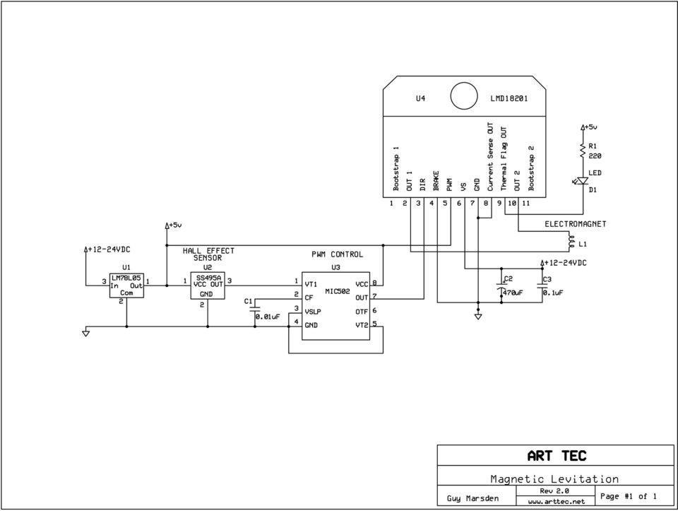
1 Parts and layout This kit contains all the components needed to build a working circuit that can control the levitation of a small permanent magnet EXCEPT the electromagnet that you provide. The electromagnet can be made from a large solenoid or relay coil, part of an electromagnetic clutch, or hand wound. This circuit will power up to 3 Amps at 24 Volts, or any powerful electromagnetic coil of 8 Ohms or higher. Parts List C1 0.01uF monolithic capacitor (beige) C2 470uF electrolytic capacitor C3 0.1uF monolithic capacitor (blue) D1 LED red LED HS1 Heat Sink for U4 L1 electromagnet electromagnet coil M1-3 magnets Rare earth magnets 3/8 diameter X 1/8 approx R1 220 Ohm 1/4 watt resistor U1 LM78L05 5 Volt regulator U2 SS495A Hall effect sensor U3 MIC502 Fan Management IC U4 LMD18201 Motor control IC Circuit board 6 of 3 conductor ribbon wire short piece of 1/8 heat shrink tubing COMPONENT PLACEMENT
 D1 LED red LED HS1 Heat Sink for U4 L1 electromagnet electromagnet coil M1-3 magnets Rare earth magnets 3/8 diameter X 1/8 approx R1 220 Ohm 1/4 watt resistor U1")
2 Assembly Instructions First things first. Unpack and identify all the components and lay them out neatly on your workbench. Now go and wash your hands - it will make you feel better and gives you a fresh start! Start by installing the smallest components first in the following order: R1,C1,C2,U3,U1,D1,C2,U4. Insert the components, bend their leads over on the back to hold them in place, double check orientation, then solder each part one at a time. C2 has a square hole for the positive (longer) lead. Install all components EXCEPT U2 which is installed on a length of ribbon wire. WIRING THE SENSOR Carefully separate the ends of the length of 3 conductor ribbon wire about 1 back and strip 1/8 of insulation from the ends, then tin the ends to keep the strands together. (Tinning means melting solder into the wire). Now cut the wires on U2 down to about 1/2 and tin the ends with a small amount of solder. Slide short lengths of 1/8 heat shrink tubing onto the ends of the ribbon wire. Hold U2 in a clamp or heatsink and solder the tinned wires to the sensor very carefully. Be sure not to overheat the sensor or damage it. Slide the shrink tubing over the soldered leads and heat the tubing with a heat gun or the end of your soldering iron (without touching). The end should look like this: Now solder the other ends into the PC board in the same order as the component leads. Note that the part number and beveled faces are facing you as in the picture. Now using 22 Gauge or thicker wire, install 2 power wires (6 or longer) into the holes marked + and -. Your board should now look like this: You can bolt the heat sink on at this time if you wish, the fins should face away from the board. All that remains is to solder 2 more wires at least 6 long into the holes on each side of U4. These wires will connect to your coil. Your Levitation Kit is now assembled and ready for calibration and testing! Let the magic begin!

3 Theory of operation POSITION SENSOR A servo system requires feedback from some kind of positional sensor. A simple way to sense the position of a magnet that is suspended below an electromagnet uses a light beam with LEDs on one side and a photo cell on the other. As the object moves, a shadow from it's upper or lower edge partially blocks the light, and changes the corresponding resistance of a photocell so that a proportional signal is generated. The drawback to me is the visual "give away" of the light beams components. My approach is to use a Hall Effect sensor with an output that is proportional to magnetic flux. Meaning that the closer to a magnet it gets, the greater the signal that it produces. My sensor of choice is a Honeywell SS490 high performance miniature ratiometric linear sensor (U2). The output of this simple 3 leaded device is at 50% of a single 5VDC supply (2.5V) in the absence of a nearby magnet. The output can go rail to rail (0 to 5V) depending on the polarity of the nearby magnet. A magnet with a north pole facing the sensor will drive the output in one direction while a south pole will drive it the other way. This provides an ideal servo proportional control signal. PWM CONTROL To make use of this signal I wanted to drive an electromagnet with a PWM (Pulse Width Modulated) signal. This is a scheme most often used to control the brightness of DC lamps and the speed of DC motors. A repeating pulse changes it's width to apply more or less power to the device over time. PWM circuits can be constructed from opamps or timer circuits, but I wanted to keep my design very simple with a really low parts count. In my research I came across a chip that is used to modulate the speed of CPU cooler fans based on the resistance of a thermistor. The chip provides only as much fan speed as is needed to cool the computer, with the side benefit of a quieter running fan. I realized that the thermistor could be replaced with any proportional signal, such as that provided by the Hall sensor. The chip is made by Micrel, part number MIC502 (U3). The pulse frequency can be set by a capacitor. A 0.1uF cap will give approximately a 100Hz signal and a 0.01uF cap will yield about 10khz. I opted for the higher frequency as it provides a more rapid response dynamic. ELECTROMAGNETIC DRIVER Since an electromagnet (or solenoid coil) has a ferrous core, the suspended permanent magnet will be attracted to it. My theory for the control is that if the suspended magnet gets too close to the electromagnet above it, the electromagnet should push it away. Conversely if it falls too low the electromagnet should work at pulling it back up, eventually reaching a balance of push and pull. This theory requires that the electromagnet can change polarity from attraction to repulsion in a proportional manner. I decided to use a motor driver chip that has a built in H- bridge switch that can reverse the polarity of it's output. I used a LM18201(U4) motor control chip that is well known to robotics hobbyists. It can control up to 3 Amps (6 Amp peak) with the appropriate heat sink. By wiring the PWM signal to the U4's DIR (pin 3) input and connecting the PWM input (pin 5) to 5V the electromagnet can be proportionately controlled from full reverse to full forward current. If the input signal is at 50% then the net effect is equal attraction and repulsion of the suspended permanent magnet. As the permanent magnet moves further away from the Hall sensor the duty cycle changes to a higher ratio that attracts the magnet, and the reverse.

4 Testing MAKING THE ELECTROMAGNET Solenoids with coils of more than 100 Ohms will draws less than half an Amp at 24 Volts so you may not need a heat sink, but your electromagnet may draw more and need it. The LED will light when U4 reaches 145F, then U4 will shut down at 180F to protect itself. A large heatsink than provided may be needed, and for loads much over 1 Amp a fan cooled heat sink would be in order. The electromagnet can be any substantial solenoid or relay coil. Look for something rated around 12VDC with a lot of pulling force -- at least 12oz pull at 1/4", preferably much more than that. You can wind your own from magnet wire, but be sure to calculate your current consumption before hooking it to the circuit so you don't exceed 3 Amps or so. I made my 32 Ohm electromagnet (shown) from a spare solenoid by replacing the plunger with a 5/16 bolt so it s head sticks out of the bottom of the coil. You can glue the shaft into the solenoid (or wrap a turn or 2 of tape around it and force it in). I also have use a small DC clutch as a magnet with a steel shaft inside it. An actual commercial lifting type electromagnet will work fine too. BUILDING A SUPPORT It is very important that the axis of the electromagnet be perfectly vertical for this design to work. So give some thought to mounting so that it can be adjusted and leveled. The sensor should be securely taped or glued to the center of the bottom of the coil, right on the shaft. Mount your solenoid at least 8" above the base to give you room to work. TESTING The circuit requires at least 12VDC from a regulated power supply, this is the minimum voltage requirement for U4, it will not work at all below about 11 Volts. U4 can handle up to 60 Volts but the circuit is limited by the 78L05's max of 30 Volts and the voltage tolerance of C2 and C3. This gives you the opportunity to "overdrive" 12V solenoids up to 24 Volts or so to enhance the performance. An adjustable power supply is be ideal for this. Take a small Neodymium magnet and tape it to the end of a plastic pen for testing. Don't glue it as you may need to flip it over to get all the polarities correct. Connect your solenoid and connect power to the circuit. Power consumption should be very low -- under 50mA for a 30 Ohm coil. Now hold the pen in your hand and slowly move it up towards the electromagnet, keeping it directly in line below the center of the coil. As it approaches the coil within about 1/2" you should begin to feel a slight push or pull. If you have a 'scope you should see a 50% waveform at pin 7 of U3 when no magnet is present. The pulse width and frequency will change as a magnet approaches, you will also see a lot of "hash" on the waveform as the circuit engages and switches the coil. You may also hear a squeal from your coil depending on it's construction and you will feel the coil switching as a vibration as you move the magnet around near it.

5 Testing p.2 POLARITIES Three things need to be in the correct magnetic polarity relative to each other in order for it to work; the coil, the Hall Effect Sensor, and the suspended magnet. If your magnet pulls toward the coil, try reversing the magnet. If the magnet still pulls toward the coil try reversing the coil wires. Eventually you will know which combination works when the pen will feel pushed away when it gets close the coil. Of course if your magnet gets too close it will be attracted to the core of the electromagnet and smack into it potentially crushing the Hall effect sensor, so take care. If you have a current meter on your power supply it will go up as the pen approaches from over 1/2" away, then go down as you hit the ideal levitation position, then go up again as you move it closer to the coil. Once you have the design tweaked the power consumption will stay relatively low during stable levitation. The wave form will be a very noisy 40-50% duty cycle CALIBRATION Once the polarities are right you will feel the magnet "grab" as it enters the "sweet spot" under the coil. At this point you should try to let the pen go very gently so you don't bump it up, down, or sideways. If it pulls up and sticks to the coil, you will need to add more weight, try sticking another magnet to the top. If it falls away, your pen is too heavy, or your electromagnet is not strong enough. If it bobbles up and down, add some ferrous metal to the suspended magnet - like some small washers. This will damp the magnetic reactance of the circuit. It will take some time to find the right weight that your combination of electromagnet and permanent magnet will lift. The range of viable weights is fairly small for any given combination of electromagnet and permanent magnet, so be prepared to do a lot of testing and changing of weights. PATIENCE IS REWARDED My design is very simple and does not use any dynamic damping as some other designs I have seen do, but those design are very complex. You can expect the levitated object to bobble up and down a bit until it stabilizes. If your weight is not right it may eventually lose control and stick to the coil or fall away. It takes some patience to learn how to carefully get the magnet into position and release it so it stays stable. It is a very spooky feeling when it all works right and the magnet pulls into place. Have fun! SEND ME IMAGES OF YOUR LEVITATED OBJECTS! I will post good quality images to my web site of your setup. them to me at: guy@arttec.net This kit is designed around the construction article that I wrote for Nuts & Volts Magazine s September 2003 issue.

6
ECEN 1400, Introduction to Analog and Digital Electronics
 ECEN 1400, Introduction to Analog and Digital Electronics Lab 4: Power supply 1 INTRODUCTION This lab will span two lab periods. In this lab, you will create the power supply that transforms the AC wall
Odyssey of the Mind Technology Fair. Simple Electronics
 Simple Electronics 1. Terms volts, amps, ohms, watts, positive, negative, AC, DC 2. Matching voltages a. Series vs. parallel 3. Battery capacity 4. Simple electronic circuit light bulb 5. Chose the right
Kit 106. 50 Watt Audio Amplifier
 Kit 106 50 Watt Audio Amplifier T his kit is based on an amazing IC amplifier module from ST Electronics, the TDA7294 It is intended for use as a high quality audio class AB amplifier in hi-fi applications
Overnight Sensations Speaker Kit
 Overnight Sensations Speaker Kit Thank you for purchasing the Overnight Sensation cabinet kit. This speaker kit was precision cut using CNC machinery for the best possible fit and finish. With a little
Servo Info and Centering
 Info and Centering A servo is a mechanical motorized device that can be instructed to move the output shaft attached to a servo wheel or arm to a specified position. Inside the servo box is a DC motor
Assembly Instructions: Shortwave Radio Kit
 Assembly Instructions: Shortwave Radio Kit MTM Scientific, Inc P.O. Box 522 Clinton, MI 49236 U.S.A Introduction Fig 1: The assembled Shortwave Radio Kit The SHORTWAVE RADIO KIT (#SWRAD) from MTM Scientific
RS232/DB9 An RS232 to TTL Level Converter
 RS232/DB9 An RS232 to TTL Level Converter The RS232/DB9 is designed to convert TTL level signals into RS232 level signals. This cable allows you to connect a TTL level device, such as the serial port on
Assembly and User Guide
 1 Amp Adjustable Electronic Load 30V Max, 1 Amp, 20 Watts Powered by: 9V Battery Assembly and User Guide Pico Load is a convenient constant current load for testing batteries and power supplies. The digital
GLOLAB Universal Telephone Hold
 GLOLAB Universal Telephone Hold 1 UNIVERSAL HOLD CIRCUIT If you have touch tone telephone service, you can now put a call on hold from any phone in the house, even from cordless phones and phones without
SYSTEM 45. C R H Electronics Design
 SYSTEM 45 C R H Electronics Design SYSTEM 45 All in one modular 4 axis CNC drive board By C R Harding Specifications Main PCB & Input PCB Available with up to 4 Axis X, Y, Z, & A outputs. Independent 25
SYSTEM 4C. C R H Electronics Design
 SYSTEM 4C C R H Electronics Design SYSTEM 4C All in one modular 4 axis CNC drive board By C R Harding Specifications Main PCB & Input PCB Available with up to 4 Axis X, Y, Z, A outputs. Independent 25
SUPER SNOOPER BIG EAR
 AA-1D Super Snooper Big Ear SPECIFICATIONS Operates on 5 to 9v DC Will drive a small speaker Provides up to 1 watt of audio power Distortion > 0.2% Voltage Gain up to 46 db Size: 1 x 1.95 Rainbowkits.com
1. The diagram below represents magnetic lines of force within a region of space.
 1. The diagram below represents magnetic lines of force within a region of space. 4. In which diagram below is the magnetic flux density at point P greatest? (1) (3) (2) (4) The magnetic field is strongest
QUASAR ELECTRONICS KIT No. 1015 ELECTRONIC MOSQUITO REPELLER
 QUASAR ELECTRONICS KIT No. 1015 ELECTRONIC MOSQUITO REPELLER General Description This simple circuit can prove itself worth many times its value (which is very reasonable anyway) in getting rid of mosquitoes
GLOLAB Two Wire Stepper Motor Positioner
 Introduction A simple and inexpensive way to remotely rotate a display or object is with a positioner that uses a stepper motor to rotate it. The motor is driven by a circuit mounted near the motor and
Q1-750 Q1-1200.2 Q1-2200.2 Q1-4500 Q2-200 Q4-90 Q4-120 HIGH PERFORMANCE AMPLIFIER
 Owner s Manual Q1-750 Q1-1200.2 Q1-2200.2 Q1-4500 Q2-200 Q4-90 Q4-120 HIGH PERFORMANCE AMPLIFIER INTRODUCTION Thanks you for purchasing SoundQubed amplifiers for your car audio systems and competitions
Magnets. Electromagnets. and. Thomas Jefferson National Accelerator Facility - Office of Science Education http://education.jlab.
 Magnets and Electromagnets Magnets and Electromagnets Can you make a magnet from a nail, some batteries and some wire? Problems Can the strength of an electromagnet be changed by changing the voltage of
MODEL OF THE ELECTROMAGNETIC LEVITATION DEVICE
 MODEL OF THE ELECTROMAGNETIC LEVITATION DEVICE Tomáš Hron CZECH TECHNICAL UNIVERSITY IN PRAGUE Faculty of Electrical Engineering Department of Electrotechnology 1. Introduction From the principal point
200W DISCRETE POWER AMPLIFIER K8060
 H8060IP-1 200W DISCRETE POWER AMPLIFIER K8060 Ideal for active speaker system or subwoofer, guitar amp, home theatre systems, instrument amp, etc. Features & Specifications Specifications: Excellent value
TECHNICAL DATASHEET #TD1404AX PWM CONTROLLED SOLENOID DRIVER
 TECHNICAL DATASHEET #TD1404AX PWM CONTROLLED SOLENOID DRIVER (PWM Input, 1.2A or 2A Output, Metal Box or PCB) PCB Board - P/N: PWMC-PCB-2A, PWMC-PCB-1.2A Packaged Driver (metal box with 1.5 m (5 ft.) cable)
Talon and Talon SR User Manual
 Talon and Talon SR User Manual Brushed DC motor controller Version 1.3 Cross the Road Electronics, LLC www.crosstheroadelectronics.com Cross The Road Electronics, LLC Page 1 4/2/2013 Device Overview Clear,
Single Transistor FM Transmitter Design
 Single Transistor FM Transmitter Design In telecommunications, frequency modulation (FM) conveys information over a carrier wave by varying its frequency. FM is commonly used at VHF radio frequencies for
Electronics and Soldering Notes
 Electronics and Soldering Notes The Tools You ll Need While there are literally one hundred tools for soldering, testing, and fixing electronic circuits, you only need a few to make robot. These tools
Joule Thief 3.0 Kit. June 2012, Rev 1 1 http://www.easternvoltageresearch.com Joule Thief 3.0
 Kit Instruction Manual Eastern Voltage Research, LLC June 2012, Rev 1 1 http://www.easternvoltageresearch.com HIGH BRIGHTNESS LED THIS KIT USES A 1W CREE, HIGH BRIGHTNESS LED. DO NOT STARE AT THIS (OR
Current Loop Tuning Procedure. Servo Drive Current Loop Tuning Procedure (intended for Analog input PWM output servo drives) General Procedure AN-015
 General Procedure AN-015") Servo Drive Current Loop Tuning Procedure (intended for Analog input PWM output servo drives) The standard tuning values used in ADVANCED Motion Controls drives are conservative and work well in over 90%
Servo Drive Current Loop Tuning Procedure (intended for Analog input PWM output servo drives) The standard tuning values used in ADVANCED Motion Controls drives are conservative and work well in over 90%
Tamura Closed Loop Hall Effect Current Sensors
 Tamura Closed Loop Hall Effect Current Sensors AC, DC, & Complex Currents Galvanic Isolation Fast Response Wide Frequency Bandwidth Quality & Reliability RoHs Compliance Closed Loop Hall Effect Sensors
PUSH BUTTON START INSTALLATION MANUAL
 PUSH BUTTON START INSTALLATION MANUAL ALTHOUGH THIS PRODUCT HAS BEEN THOROUGHLY TESTED KPIERSON TECHNOLOGIES ASSUMES NO RESPONSIBILITY FOR ANY DAMAGE THAT MAY RESULT BY THE INSTALLATION OF THIS PRODUCT.
SYMMETRIC 1A POWER SUPPLY K8042
 SYMMETRIC 1A POWER SUPPLY K8042 Low cost universal symmetric power supply ILLUSTRATED ASSEMBLY MANUAL H8042IP-1 Features & Specifications Features low cost universal symmetric power supply just add a suitable
BUILDING INSTRUCTIONS
 etap2hw 38 mm I2C to LCD Interface BUILDING INSTRUCTIONS October 2013 P. Verbruggen Rev 1.01 15-Oct-13 Page 1 Table of Contents Chapter 1 General Information 1.1 ESD Precautions 1.2 Further Supplies 1.3
Total solder points: 57 Difficulty level: beginner 1 2 3 4 5 advanced 3 TO 30VDC / 3A POWER SUPPLY K7203 ILLUSTRATED ASSEMBLY MANUAL H7203IP-1
 Total solder points: 57 Difficulty level: beginner 1 2 3 4 5 advanced 3 TO 30VDC / 3A POWER SUPPLY K7203 A power supply for all our kits, based on a stabilised DC voltage of 30V. ILLUSTRATED ASSEMBLY MANUAL
How to replace the ribbon in the Fountek JP3 tweeter
 10 August 2004 1 How to replace the ribbon in the Fountek JP3 tweeter These are the tools needed to replace the ribbon. The slide gauge is not needed; any ordinary ruler will do. A scalpel (+ fresh blade)
Build Your Own Solar Car Teach build learn renewable Energy! Page 1 of 1
 Solar Car Teach build learn renewable Energy! Page 1 of 1 Background Not only is the sun a source of heat and light, it s a source of electricity too! Solar cells, also called photovoltaic cells, are used
Modifying the Yaesu FT-847 External 22.625 MHz Reference Input
 Modifying the Yaesu FT-847 External 22.625 MHz Reference Input David Smith VK3HZ Introduction This document describes the modification of an FT-847 to allow an external 22.625 MHz Reference oscillator
TruPower-Portable-500W. Solar Starter kit
 TruPower-Portable-500W Solar Starter kit This Solar starter kit is an easy to use solar power supply system that is the complete solution for all your solar power needs. It is a solar generator that converts
Welcome to this presentation on LED System Design, part of OSRAM Opto Semiconductors LED 101 series.
 Welcome to this presentation on LED System Design, part of OSRAM Opto Semiconductors LED 101 series. 1 To discuss the design challenges of LED systems we look at the individual system components. A basic
Duct Humidity Transmitter
 SDC-H Duct Humidity Transmitter Features Replaceable sensor element Humidity measurement for air ducts Minimum and maximum value memory 0 0V, 0 0mA or 0V, 4 0mA measuring signals selectable with jumpers
Analog control unit for mobile robots
 Analog control unit for mobile robots Soldering kit for experimentation For Fischertechnik robots and others Most diverse functions Requires no programming Patented sensor technology Summary We are pleased
ATL Fuel Level Sender Probes
 T E C H N I C A L S P E C I F I C A T I O N The ATL EL-AD-151 (Resistance Output) and EL-AD-152 (Voltage Output) Fuel Level Senders are highly advanced sensors for continuously measuring the contents of
Principles of Adjustable Frequency Drives
 What is an Adjustable Frequency Drive? An adjustable frequency drive is a system for controlling the speed of an AC motor by controlling the frequency of the power supplied to the motor. A basic adjustable
Whale 3. User Manual and Installation Guide. DC Servo drive. Contents. 1. Safety, policy and warranty. 1.1. Safety notes. 1.2. Policy. 1.3. Warranty.
 Whale 3 DC Servo drive User Manual and Installation Guide Contents 1. Safety, policy and warranty. 1.1. Safety notes. 1.2. Policy. 1.3. Warranty. 2. Electric specifications. 2.1.Operation ranges. 3. Connections
Panasonic Microwave Oven Inverter HV Power Supply
 Panasonic Microwave Oven Inverter HV Power Supply David Smith VK3HZ (vk3hz (*at*) wia.org.au) This particular power supply comes from a circa-2000 Panasonic Microwave model NN-S550WF. Nearly all Panasonic
!Operation:!1. Connect an external power source to J1 (+ and - IN terminals). The
. The") The CB500 Electronic Circuit Breaker is an resettable circuit breaker (fuse) that disconnects power when the trip setting is exceeded. There are 4 trip settings that can easily be changed and set during
The CB500 Electronic Circuit Breaker is an resettable circuit breaker (fuse) that disconnects power when the trip setting is exceeded. There are 4 trip settings that can easily be changed and set during
Kit 27. 1W TDA7052 POWER AMPLIFIER
 Kit 27. 1W TDA7052 POWER AMPLIFIER This is a 1 watt mono amplifier Kit module using the TDA7052 from Philips. (Note, no suffix.) It is designed to be used as a building block in other projects where a
K6002 TEMPERATURE CONTROLLER. Specifications
 Total solder points: 169 + 99 + 67 Difficulty level: beginner 1 2 3 4 5 advanced TEMPERATURE CONTROLLER K6002 Unlike a normal thermostat, this kit has two outputs, one for "high" alarm and one for "low"
FUEL-16, Troubleshooting Fuel Supply Problems
 FUEL-16, Troubleshooting Fuel Supply Problems Introduction This procedure is used to troubleshooting fuel supply problems including failure of the fuel pump to start during engine cranking. Fuel Pump Not
Using and Wiring Light Emitting Diodes (LEDs) for Model Railroads
 for Model Railroads") Using and Wiring Light Emitting Diodes (LEDs) for Model Railroads LEDs have many useful applications in Model railroading, including: Locomotive headlights Rear-end warning lights for cabooses and passenger
Using and Wiring Light Emitting Diodes (LEDs) for Model Railroads LEDs have many useful applications in Model railroading, including: Locomotive headlights Rear-end warning lights for cabooses and passenger
RADIANT PLASMA 4700 Plasma Spark Generator
 RADIANT PLASMA 4700 Plasma Spark Generator Installation Guide / User Manual A S P A R K O F F R E S H A I R Aquapulser.com Contents 1 Introduction 2 1.1 About the Product....................................
Soldering Techniques N I A G A R A C O L L E G E T E C H N O L O G Y D E P T.
 Soldering Techniques N I A G A R A C O L L E G E T E C H N O L O G Y D E P T. Soldering 101 Soldering is the process of joining two metals together to form an electrically and mechanically secure bond
Redesigned by Laurier Gendron (Aug 2006 ) Download this project in PDF. Horn circuit. Train Circuitry
 Download this project in PDF. Horn circuit. Train Circuitry") Redesigned by Laurier Gendron (Aug 2006 ) Download this project in PDF Train Circuitry Horn circuit New Design After many comments by interested hobbyists not being able to obtain parts like the LM566
Redesigned by Laurier Gendron (Aug 2006 ) Download this project in PDF Train Circuitry Horn circuit New Design After many comments by interested hobbyists not being able to obtain parts like the LM566
Micrio WS1 Replacement Wind Speed Sensor and WC1 Replacement Wind Compass Sensor for Raymarine ST50 and ST60 Wind Instruments. Rev 4.
 Micrio WS1 Replacement Wind Speed Sensor and WC1 Replacement Wind Compass Sensor for Raymarine ST50 and ST60 Wind Instruments. Rev 4.1 The Micrio WS1 Wind Speed Sensor and WC1 Compass Sensor are direct
Line Reactors and AC Drives
 Line Reactors and AC Drives Rockwell Automation Mequon Wisconsin Quite often, line and load reactors are installed on AC drives without a solid understanding of why or what the positive and negative consequences
Electric Motor. Your Activity Build a simple electric motor. Material. Create. Science Topics. What s going on? 2 Jumbo Safety Pins (or Paper Clips)
") Electric Motor Your Activity Build a simple electric motor Material D-Cell Battery Coil made out of magnet wire 2 Jumbo Safety Pins (or Paper Clips) Scissors (or sand paper) 1 Rubber Band Ceramic Magnet
Electric Motor Your Activity Build a simple electric motor Material D-Cell Battery Coil made out of magnet wire 2 Jumbo Safety Pins (or Paper Clips) Scissors (or sand paper) 1 Rubber Band Ceramic Magnet
LG Air Conditioning Multi F(DX) Fault Codes Sheet. Multi Split Units
 Fault Codes Sheet. Multi Split Units") Multi Split Units If there is a fault on any LG Multi unit, an Error mark is indicated on the display window of the indoor unit, wired-remote controller, and LED s of outdoor unit control board. A two
Multi Split Units If there is a fault on any LG Multi unit, an Error mark is indicated on the display window of the indoor unit, wired-remote controller, and LED s of outdoor unit control board. A two
Optical Sensor Interface for AFX Digital LED Timer/Counter by George Warner, Jan. 2003 warnergt@ptd.net
 Optical Sensor Interface for AFX Digital LED Timer/Counter by George Warner, Jan. 200 warnergt@ptd.net Abstract This paper presents a design for an optical sensor interface to an AFX Digital LED Timer/Counter.
INSTALLATION INSTRUCTIONS FOR G205 AND G207 STICK GRIPS
 1341 Distribution Way STe 15, Vista, A 92081 USA Ph 760.599.4720 Fx 760.599.4383 INSTALLATION INSTRUTIONS FOR G205 AND G207 STIK GRIPS G205 G207 Warning: Installation and use of Ray Allen ompany products
LM 358 Op Amp. If you have small signals and need a more useful reading we could amplify it using the op amp, this is commonly used in sensors.
 LM 358 Op Amp S k i l l L e v e l : I n t e r m e d i a t e OVERVIEW The LM 358 is a duel single supply operational amplifier. As it is a single supply it eliminates the need for a duel power supply, thus
LS-1 Series Tungsten Halogen Light Sources Installation and Operation Instructions
 LS-1 Series Tungsten Halogen Light Sources Installation and Operation Instructions Description The LS-1 Series of tungsten halogen light sources are versatile, white-light lamps optimized for use in the
WIRE, TERMINAL AND CONNECTOR REPAIR CONDUCTORS
 CONDUCTORS Conductors are needed to complete the path for electrical current to flow from the power source to the working devices and back to the power source. Special wiring is needed for battery cables
User manual DinaSys DTC/DTS and DTC/DTZ
 PiCommIT has developed the DinaSys DTC/DTS and DinaSys DTC/DTZ turntable controller for the Fleischmann / Marklin Turntables in scale H0, H0m, TT, N and Z. One of the most important starting point was
Physical Specifications (Custom design available.)
") Helmholtz Coils A useful laboratory technique for getting a fairly uniform magnetic field, is to use a pair of circular coils on a common axis with equal currents flowing in the same sense. For a given
Helmholtz Coils A useful laboratory technique for getting a fairly uniform magnetic field, is to use a pair of circular coils on a common axis with equal currents flowing in the same sense. For a given
1-Stainless Steel conical fermenter with a thermometer setup.
 The following instructions should help you modify your existing fermentation vessel into a temperature controlled fermenter. The reason I built this setup is because I was tired of my brews getting too
DIRECT CURRENT GENERATORS
 DIRECT CURRENT GENERATORS Revision 12:50 14 Nov 05 INTRODUCTION A generator is a machine that converts mechanical energy into electrical energy by using the principle of magnetic induction. This principle
Electronic Circuit Construction:
 Electronic Circuit Construction: Various methods are used for building electronic circuits. The method that you choose depends on a number of factors, including the resources available to you and whether
How to modify a car starter for forward/reverse operation
 How to modify a car starter for forward/reverse operation Ok, start by choosing a starter. I took a starter out of an older style Nissan Sentra. I chose this particular starter for two reasons: 1. It was
MODEL 2202IQ (1991-MSRP $549.00)
") F O R T H E L O V E O F M U S I C F O R T H E L O V E O F M U S I C MODEL 2202IQ (1991-MSRP $549.00) OWNER'S MANUAL AND INSTALLATION GUIDE INTRODUCTION Congratulations on your decision to purchase a LINEAR
F O R T H E L O V E O F M U S I C F O R T H E L O V E O F M U S I C MODEL 2202IQ (1991-MSRP $549.00) OWNER'S MANUAL AND INSTALLATION GUIDE INTRODUCTION Congratulations on your decision to purchase a LINEAR
Preview of Period 16: Motors and Generators
 Preview of Period 16: Motors and Generators 16.1 DC Electric Motors What causes the rotor of a motor to spin? 16.2 Simple DC Motors What causes a changing magnetic field in the simple coil motor? 16.3
Relays High Capacity 50 Amp Mini Relays Standard Mini Relays Micro Relays Power Relays Connector Modules
 CHIEF EN TERPRISES INC. M a s t e r I n t e r n a t i o n a l D i s t r i b u t o r Relays High Capacity 50 Amp Mini Relays Standard Mini Relays Micro Relays Power Relays Connector Modules M AS TER IN
PowerAmp Design. PowerAmp Design PAD135 COMPACT HIGH VOLATGE OP AMP
 PowerAmp Design COMPACT HIGH VOLTAGE OP AMP Rev G KEY FEATURES LOW COST SMALL SIZE 40mm SQUARE HIGH VOLTAGE 200 VOLTS HIGH OUTPUT CURRENT 10A PEAK 40 WATT DISSIPATION CAPABILITY 200V/µS SLEW RATE APPLICATIONS
Measuring Impedance and Frequency Response of Guitar Pickups
 Measuring Impedance and Frequency Response of Guitar Pickups Peter D. Hiscocks Syscomp Electronic Design Limited phiscock@ee.ryerson.ca www.syscompdesign.com April 30, 2011 Introduction The CircuitGear
Three Axis TB6560 CNC Driver Users Manual
 Three Axis TB6560 CNC Driver Users Manual Revision 2.0 Oct. 16. 2009 1 Content 1. GENERAL INFORMATION... 3 1.1. Scope... 3 1.2. General Description... 3 2. Descriptions of 3-AXIS CNC Board... 3 2.1. Photo
400W MONO/STEREO AMPLIFIER
 400W MONO/STEREO AMPLIFIER Universal, robust and compact are the words to describe this amplifier. Total solder points: 264 Difficulty level: beginner 1 2 3 4 5 advanced K4005B ILLUSTRATED ASSEMBLY MANUAL
Installation Guide. WSD-100 Wind Speed and Direction Sensor For XR5 Data Loggers. February, 2011
 WSD-100 Wind Speed and Direction Sensor For XR5 Data Loggers Installation Guide February, 2011 Pace Scientific Inc www.pace-sci.com Tel: 704-799-0688 sales@pace-sci.com 1 Disclaimer The following warranty
Current Probes. User Manual
 Current Probes User Manual ETS-Lindgren L.P. reserves the right to make changes to any product described herein in order to improve function, design, or for any other reason. Nothing contained herein shall
2. Remove rear cover of head lamp if bulbs are covered/sealed within the housings, and remove halogen bulb carefully.
 These instructions are designed to address most general installation procedures across vehicles and should not be considered vehicle make, model or year specific. Please contact the vendor directly for
Phoenixtech Brushless Motor Speed Controller Programming Guide
 Congratulations on the purchase of your new Phoenixtech Brushless Motor Speed Controller. This latest series of controllers is unique in that it is equipped with a robust internal switching Battery Eliminator
The $25 Son of a cheap timer This is not suitable for a beginner. You must have soldering skills in order to build this kit.
 The $25 Son of a cheap timer This is not suitable for a beginner. You must have soldering skills in order to build this kit. Micro Wizard has been manufacturing Pinewood Derby timers for over 10 years.
1218-75 Watt Audiophile Audio Amplifier
 Description Quasar kit No.1218 is part of a new line of constructions which combined form a full stereo system. The line consists of the following KITS Quasar kit No.1214 6 inputs stereo selector Quasar
Cell Phone Charging Purse
 Cell Phone Charging Purse Created by Becky Stern Last updated on 2015-02-20 01:00:16 PM EST Guide Contents Guide Contents Overview Prepare USB and Power Supply Create a Charging Shelf Install Coil in Bag
TIMING SIGNALS, IRIG-B AND PULSES
 TIMING SIGNALS, IRIG-B AND PULSES Document No. PD0043200B July 2013 Arbiter Systems, Inc. 1324 Vendels Circle, Suite 121 Paso Robles, CA 93446 U.S.A. (805) 237-3831, (800) 321-3831 http://www.arbiter.com
K8025 VIDEO PATTERN GENERATOR. Check the picture quality of your monitor or TV, ideal for adjustment or troubleshooting.
 K8025 ILLUSTRATED ASSEMBLY MANUAL H8025IP 1 VIDEO PATTERN GENERATOR Check the picture quality of your monitor or TV, ideal for adjustment or troubleshooting. Forum Participate our Velleman Projects Forum
AUTOMOTIVE LED LIGHT CATALOG
 AUTOMOTIVE LED LIGHT CATALOG #74 Wedge Flat LED Light 44423 #74 (T5) Wedge Flat LED Light. 1 LED. Durable, shock and vibration proof, instant On/Off. Monochromatic (pure) color, low heat generation, virtually
INSTALLATION AND OPERATING INSTRUCTIONS For Model GL1 Gate Locks
 Securitron Magnalock Corp. www.securitron.com ASSA ABLOY, the global leader Tel 800.624.5625 techsupport@securitron.com in door opening solutions INSTALLATION AND OPERATING INSTRUCTIONS For Model GL1 Gate
www.the Floor Heating Warehouse.co.uk
 www.the Floor Heating Warehouse.co.uk Underfloor Heating Installation Guide (Grundfoss Pump System) General Overview: Our water based underfloor heating system can be installed by your own plumber or heating
Unit 24: Applications of Pneumatics and Hydraulics
 Unit 24: Applications of Pneumatics and Hydraulics Unit code: J/601/1496 QCF level: 4 Credit value: 15 OUTCOME 2 TUTORIAL 4 DIRECTIONAL CONTROL VALVES The material needed for outcome 2 is very extensive
Pulse Width Modulated (PWM) Controller for 12 Volt Motors
 Controller for 12 Volt Motors") Pulse Width Modulated (PWM) Controller for 12 Volt Motors This electronic controller is designed to allow a user to vary the speed and power output of a typical 12 volt motor such as a fuel pump, water
Pulse Width Modulated (PWM) Controller for 12 Volt Motors This electronic controller is designed to allow a user to vary the speed and power output of a typical 12 volt motor such as a fuel pump, water
Product Specification
 Product Specification Model No.: DC-240-L01-00-TR Description: H=3.00mm Horizontal SMD DC Power Jacks Pin Shaft Diameter: 0.65mm Packing Method: Tape & Reel (600pcs./R) 1. General 1a. Scope The jacks should
Bill Conkling July 2012
 Bill Conkling July 2012 Introduction: For any ham, there are moments that are priceless, like snagging that elusive rare DX station on a deserted island that hasn t been activated in 52 years. And certainly,
HERZ-Thermal Actuators
 HERZ-Thermal Actuators Data Sheet 7708-7990, Issue 1011 Dimensions in mm 1 7710 00 1 7710 01 1 7711 18 1 7710 80 1 7710 81 1 7711 80 1 7711 81 1 7990 00 1 7980 00 1 7708 11 1 7708 10 1 7708 23 1 7709 01
OPERATING MANUAL. Table of contents. 2 Phase Stepping Motor Driver 2M542. Rev. A. Introduction page 2. Specifications page 2 Timing chart page 3
 2 Phase Stepping Motor Driver 2M542 OPEATING MANUAL Table of contents Introduction page 2 Specifications page 2 Timing chart page 3 Setting page 4 Current set page 4 educe current function page 4 Micro
High voltage power supply (1 to 20 KV)
") High voltage power supply ( to 0 KV) Ammar Ahmed Khan, Muhammad Wasif, Muhammad Sabieh Anwar This documentation is divided into two parts, the first part provides a brief overview about the key features
High voltage power supply ( to 0 KV) Ammar Ahmed Khan, Muhammad Wasif, Muhammad Sabieh Anwar This documentation is divided into two parts, the first part provides a brief overview about the key features
GT Sensors Precision Gear Tooth and Encoder Sensors
 GT Sensors Precision Gear Tooth and Encoder Sensors NVE s GT Sensor products are based on a Low Hysteresis GMR sensor material and are designed for use in industrial speed applications where magnetic detection
Build A Video Switcher. Reprinted with permission from Electronics Now Magazine September 1997 issue
 Build A Video Switcher Reprinted with permission from Electronics Now Magazine September 1997 issue Copyright Gernsback Publications, Inc.,1997 BUILD A VIDEO SWITCHER FRANK MONTEGARI Watch several cameras
APPLICATION NOTES: Dimming InGaN LED
 APPLICATION NOTES: Dimming InGaN LED Introduction: Indium gallium nitride (InGaN, In x Ga 1-x N) is a semiconductor material made of a mixture of gallium nitride (GaN) and indium nitride (InN). Indium
Cheap Antennas for the AMSAT LEO's Kent Britain -- WA5VJB
 Cheap Antennas for the AMSAT LEO's Kent Britain -- WA5VJB Cheap LEO Antenna Drew, KO4MA, using the Cheap LEO antenna during a Dayton AMSAT LEO Demonstration Hand held dual band antennas are popular for
Transfer of Energy Forms of Energy: Multiple Transformations
 Transfer of Energy Forms of Energy: Multiple Transformations Discovery Question What energy transformations are used in everyday devices? Introduction Thinking About the Question Materials Safety Trial
FREEBIRD THE ORIGINAL D.I.Y. ORNITHOPTER! Tools and Glue. Required Materials
 Do not try to make your ornithopter using "household materials". If you want it to fly, you have to build it right. FREEBIRD THE ORIGINAL D.I.Y. ORNITHOPTER! Wingspan: 16 inches Weight: 1/4 ounce The Ornithopter
An Easy to Build and Operate Induction Generator
 An Easy to Build and Operate Induction Generator Believe it or not, nearly everyone you know has at least one induction generator and probably more That's right! You say that is impossible... well, read
Adding Heart to Your Technology
 RMCM-01 Heart Rate Receiver Component Product code #: 39025074 KEY FEATURES High Filtering Unit Designed to work well on constant noise fields SMD component: To be installed as a standard component to
I. R. D. T INSTITUTE OF RESEARCH DEVELOPMENT AND TRAINING
 I. R. D. T INSTITUTE OF RESEARCH DEVELOPMENT AND TRAINING SYLLABUS SIX MONTHS FULL TIME Repair and Maintenance of Electrical gadgets EFFECTIVE FROM:- UNDER DEVELOPMENT Prepared By: Curriculum Development
Permanent Magnetic Generator Construction Manual
 Permanent Magnetic Generator Construction Manual http://hojomotor.com Our Team Doing an On-site Assembly in Peru http://hojomotor.com Section 1) Introduction This manual describes how to build a 'permanent