The Schmidt-Czerny-Turner Spectrograph
|
|
|
- Melissa King
- 7 years ago
- Views:
Transcription
1 The Schmidt-Czerny-Turner Spectrograph 2012 Advanced Materials Characterization Workshop June 7, 2012 Jason McClure Chief Scientist Princeton Instruments

2 Outline Czerny-Turner imaging spectrograph Applications Limitations of the traditional design image aberrations Schmidt-Czerny-Turner spectrograph Application Highlights Hyper-spectral imaging

3 Applications involving the CT-Spectrograph Raman, PL, PLE Transmittance / Reflectance Spectral domain Optical Coherence Tomography (OCT) Fourier Domain Dispersive Spectroscopy There is a movement towards multimodality techniques that generate information rich data at the micro/nano scale Hyperspectral micro-raman imaging TERS, NSOM OCT/micro-Raman mapping cancer detection MRI/X-ray CT/Photoluminescence Small animal imaging

4 Applications involving the CT-Spectrograph Where are the innovations occurring?


5 Applications involving the CT-Spectrograph Where are the innovations occurring? Nature Nanotechnology 4, (2009) Published online: 26 July 2009

6 Applications involving the CT-Spectrograph Where are the innovations occurring?

7 Applications involving the CT-Spectrograph Where are the innovation occurring?


8 Applications involving the CT-Spectrograph Where are the innovations occurring??

9 The Czerny-Turner Spectrograph The CT spectrograph has not seen significant innovation in ~30 years! Strong movement towards multimodality techniques which require spatially resolved spectral data The CT spectrograph is the final optical element light sees before your detector does. There are three primary image aberrations that can be observed in any traditional CT type spectrograph Spherical Coma Astigmatism


10 Image Aberrations Spherical aberration Cause: Using a spherical mirrors to focus light to form an image Appearance: Diffuse symmetric blur about an image e.g. image of a fiber through a spectrograph will have a diffuse blur around a more intense center Affects on spectroscopy: Limits both spatial and spectral resolution of a spectrograph Example: Symmetric blur seen about a fiber optic image 150 um fiber core Wavefront Aberration W I 1 f # 3


11 Image Aberrations Coma aberration Cause: Using mirrors to image a source off axis Appearance: Comet shaped tail to focused images or spectral lines e.g. spectral lines are asymmetrically broadened Affects on spectroscopy: Limits spectral resolution of a spectrograph, however, is completely corrected at one grating angle or wavelength. Example: Asymmetry in spectral line profile Wavefront Aberration W II 1 f # 2


12 Image Aberrations Astigmatism aberration Cause: Using lenses or mirrors to image a source off axis Appearance: Vertical or horizontal elongation of an image e.g. The Bow-Tie effect, vertical distortion of fiber image Affects on spectroscopy: Limits both spectral and spatial resolution of a spectrograph. Is completely corrected at the center of the focal plane. Example: Elongation of Fiber core images Traditional CT focal plane Wavefront Aberration W III f 1 #

13 Image Aberrations Astigmatism aberration Cause: Using lenses or mirrors to image a source off axis Appearance: Vertical or horizontal elongation of an image e.g. The Bow-Tie effect, vertical distortion of fiber image Affects on spectroscopy: Limits both spectral and spatial resolution of a spectrograph. Is completely corrected at the center of the focal plane.

14 Image Aberrations Astigmatism aberration Cause: Using lenses or mirrors to image a source off axis Appearance: Vertical or horizontal elongation of an image e.g. The Bow-Tie effect, vertical distortion of fiber image Affects on spectroscopy: Limits both spectral and spatial resolution of a spectrograph. Is completely corrected at the center of the focal plane.


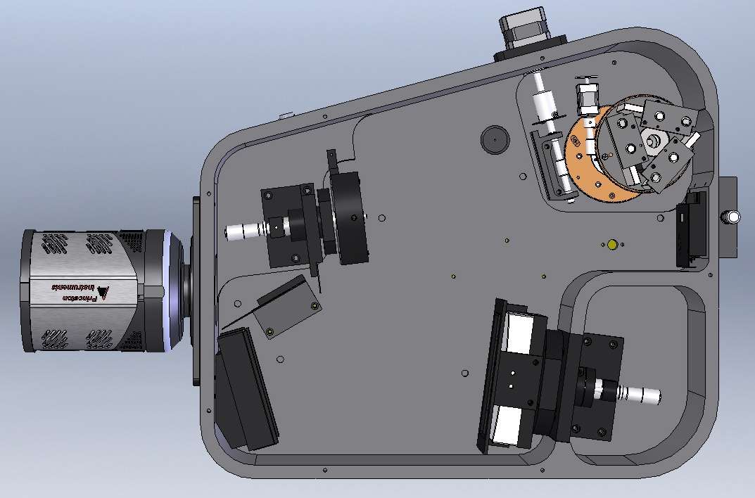
15 Current state Schmidt-Czerny-Turner of the art spectrograph f/4 class spectrograph Row # Wavelength Dispersed image of a continuous source (QTH Lamp)

16


17 Application Highlight - Hyperspectral Imaging 1 um monodisperse polystyrene spheres Self assemble into 2D hcp arrays Dark field illumination Diffraction through multilayer Annular aperture PMMA array 10 mm Objective Olympus IX X Illumination

18 Application Highlight - Hyperspectral Imaging 10X dark field illumination of PMMA lattice Witness camera on IX-71 0 order image seen through SCT

19 Application Highlight - Hyperspectral Imaging Row # Full 2D spectral image Entrance Slit Wavelength

20 Application Highlight - Hyperspectral Imaging Spectra from two differently oriented grains Dark field QTH illumination, Line exposure time = 0.1 sec Objective lens = Olympus 10X APO Grating = 1200 g/mm blazed at 500 nm Spectrometer slit = 20 um Resulting Hyperspectral image

21 Application Highlight - Hyperspectral Imaging Data collected using NanoPhoton Confocal Microscope
22 Acknowledgements Acton Engineering Lloyd Wentzell Bob Fancy Mike Case Paulo Goulart Bob Jarratt Trenton Engineering Bill Asher Harry Grannis Bob Bolkus Bill Hartman Katsumasa Lab Osaka University Isoplane testing with NanoPhoton confocal microscope

23 Questions?
24 Features Feature Aperture ratio Focal length Wavelength Scan Range CCD resolution Astigmatism Coma Spherical Aberration Specification f/ mm nm 0.07nm *4mm x 10 um slit at 435nm 0.0 um *any wavelength 0.0 um *at 500 nm with 1200 g/mm grating 0.0 um *any wavelength
Introduction to reflective aberration corrected holographic diffraction gratings
 Introduction to reflective aberration corrected holographic diffraction gratings By Steve Slutter, Wu Jiang, and Olivier Nicolle The reflective diffraction grating is the heart of most spectroscopy systems
Understanding astigmatism Spring 2003
 MAS450/854 Understanding astigmatism Spring 2003 March 9th 2003 Introduction Spherical lens with no astigmatism Crossed cylindrical lenses with astigmatism Horizontal focus Vertical focus Plane of sharpest
Preface Light Microscopy X-ray Diffraction Methods
 Preface xi 1 Light Microscopy 1 1.1 Optical Principles 1 1.1.1 Image Formation 1 1.1.2 Resolution 3 1.1.3 Depth of Field 5 1.1.4 Aberrations 6 1.2 Instrumentation 8 1.2.1 Illumination System 9 1.2.2 Objective
Lecture 20: Scanning Confocal Microscopy (SCM) Rationale for SCM. Principles and major components of SCM. Advantages and major applications of SCM.
 Rationale for SCM. Principles and major components of SCM. Advantages and major applications of SCM.") Lecture 20: Scanning Confocal Microscopy (SCM) Rationale for SCM. Principles and major components of SCM. Advantages and major applications of SCM. Some limitations (disadvantages) of NSOM A trade-off
Lecture 20: Scanning Confocal Microscopy (SCM) Rationale for SCM. Principles and major components of SCM. Advantages and major applications of SCM. Some limitations (disadvantages) of NSOM A trade-off
Realization of a UV fisheye hyperspectral camera
 Realization of a UV fisheye hyperspectral camera Valentina Caricato, Andrea Egidi, Marco Pisani and Massimo Zucco, INRIM Outline Purpose of the instrument Required specs Hyperspectral technique Optical
Modern Classical Optics
 Modern Classical Optics GEOFFREY BROOKER Department of Physics University of Oxford OXPORD UNIVERSITY PRESS Contents 1 Electromagnetism and basic optics 1 1.1 Introduction 1 1.2 The Maxwell equations 1
Fig.1. The DAWN spacecraft
 Introduction Optical calibration of the DAWN framing cameras G. Abraham,G. Kovacs, B. Nagy Department of Mechatronics, Optics and Engineering Informatics Budapest University of Technology and Economics
Endoscope Optics. Chapter 8. 8.1 Introduction
 Chapter 8 Endoscope Optics Endoscopes are used to observe otherwise inaccessible areas within the human body either noninvasively or minimally invasively. Endoscopes have unparalleled ability to visualize
Introduction to Optics
 Second Edition Introduction to Optics FRANK L. PEDROTTI, S.J. Marquette University Milwaukee, Wisconsin Vatican Radio, Rome LENO S. PEDROTTI Center for Occupational Research and Development Waco, Texas
WAVELENGTH OF LIGHT - DIFFRACTION GRATING
 PURPOSE In this experiment we will use the diffraction grating and the spectrometer to measure wavelengths in the mercury spectrum. THEORY A diffraction grating is essentially a series of parallel equidistant
Chapter 6 Telescopes: Portals of Discovery. How does your eye form an image? Refraction. Example: Refraction at Sunset.
 Chapter 6 Telescopes: Portals of Discovery 6.1 Eyes and Cameras: Everyday Light Sensors Our goals for learning:! How does your eye form an image?! How do we record images? How does your eye form an image?
Flat-Field IR Mega-Pixel Lens
 Flat-Field Mega-Pixel Lens Series Flat-Field Mega-Pixel Lens Flat-Field Mega-Pixel Lens 20.ver.02 E Specifications and Lineup Full MP Image Model Imager Size Mount Focal Length Aperture Range Zoom Ratio
Optical Systems Design with Zemax OpticStudio. Lecture 1
 Optical Systems Design with Zemax OpticStudio Lecture 1 Why Optical Systems Design Optical system design is no longer a skill reserved for a few professionals. With readily available commercial optical
IMPROVED CCD DETECTORS FOR HIGH SPEED, CHARGE EXCHANGE SPECTROSCOPY STUDIES ON THE DIII D TOKAMAK
 IMPROVED CCD DETECTORS FOR HIGH SPEED, CHARGE EXCHANGE SPECTROSCOPY STUDIES ON THE TOKAMAK by K.H. Burrell P. Gohil, R.J. Groebner, D.H. Kaplan, D.G. Nilson,* J.I. Robinson, and D.M. Thomas General Atomics,
DOING PHYSICS WITH MATLAB COMPUTATIONAL OPTICS RAYLEIGH-SOMMERFELD DIFFRACTION INTEGRAL OF THE FIRST KIND
 DOING PHYSICS WITH MATLAB COMPUTATIONAL OPTICS RAYLEIGH-SOMMERFELD DIFFRACTION INTEGRAL OF THE FIRST KIND THE THREE-DIMENSIONAL DISTRIBUTION OF THE RADIANT FLUX DENSITY AT THE FOCUS OF A CONVERGENCE BEAM
Rodenstock Photo Optics
 Rogonar Rogonar-S Rodagon Apo-Rodagon N Rodagon-WA Apo-Rodagon-D Accessories: Modular-Focus Lenses for Enlarging, CCD Photos and Video To reproduce analog photographs as pictures on paper requires two
Study of the Human Eye Working Principle: An impressive high angular resolution system with simple array detectors
 Study of the Human Eye Working Principle: An impressive high angular resolution system with simple array detectors Diego Betancourt and Carlos del Río Antenna Group, Public University of Navarra, Campus
Optical laser beam scanner lens relay system
 1. Introduction Optical laser beam scanner lens relay system Laser beam scanning is used most often by far in confocal microscopes. There are many ways by which a laser beam can be scanned across the back
How an electronic shutter works in a CMOS camera. First, let s review how shutters work in film cameras.
 How an electronic shutter works in a CMOS camera I have been asked many times how an electronic shutter works in a CMOS camera and how it affects the camera s performance. Here s a description of the way
Grazing incidence wavefront sensing and verification of X-ray optics performance
 Grazing incidence wavefront sensing and verification of X-ray optics performance Timo T. Saha, Scott Rohrbach, and William W. Zhang, NASA Goddard Space Flight Center, Greenbelt, Md 20771 Evaluation of
Revision problem. Chapter 18 problem 37 page 612. Suppose you point a pinhole camera at a 15m tall tree that is 75m away.
 Revision problem Chapter 18 problem 37 page 612 Suppose you point a pinhole camera at a 15m tall tree that is 75m away. 1 Optical Instruments Thin lens equation Refractive power Cameras The human eye Combining
Optical Metrology. Third Edition. Kjell J. Gasvik Spectra Vision AS, Trondheim, Norway JOHN WILEY & SONS, LTD
 2008 AGI-Information Management Consultants May be used for personal purporses only or by libraries associated to dandelon.com network. Optical Metrology Third Edition Kjell J. Gasvik Spectra Vision AS,
Diffraction of a Circular Aperture
 Diffraction of a Circular Aperture Diffraction can be understood by considering the wave nature of light. Huygen's principle, illustrated in the image below, states that each point on a propagating wavefront
C) D) As object AB is moved from its present position toward the left, the size of the image produced A) decreases B) increases C) remains the same
 D) As object AB is moved from its present position toward the left, the size of the image produced A) decreases B) increases C) remains the same") 1. For a plane mirror, compared to the object distance, the image distance is always A) less B) greater C) the same 2. Which graph best represents the relationship between image distance (di) and object
1. For a plane mirror, compared to the object distance, the image distance is always A) less B) greater C) the same 2. Which graph best represents the relationship between image distance (di) and object
Holographically corrected microscope with a large working distance (as appears in Applied Optics, Vol. 37, No. 10, 1849-1853, 1 April 1998)
") Holographically corrected microscope with a large working distance (as appears in Applied Optics, Vol. 37, No. 10, 1849-1853, 1 April 1998) Geoff Andersen and R. J. Knize Laser and Optics Research Center
Holographically corrected microscope with a large working distance (as appears in Applied Optics, Vol. 37, No. 10, 1849-1853, 1 April 1998) Geoff Andersen and R. J. Knize Laser and Optics Research Center
2) A convex lens is known as a diverging lens and a concave lens is known as a converging lens. Answer: FALSE Diff: 1 Var: 1 Page Ref: Sec.
 A convex lens is known as a diverging lens and a concave lens is known as a converging lens. Answer: FALSE Diff: 1 Var: 1 Page Ref: Sec.") Physics for Scientists and Engineers, 4e (Giancoli) Chapter 33 Lenses and Optical Instruments 33.1 Conceptual Questions 1) State how to draw the three rays for finding the image position due to a thin
Physics for Scientists and Engineers, 4e (Giancoli) Chapter 33 Lenses and Optical Instruments 33.1 Conceptual Questions 1) State how to draw the three rays for finding the image position due to a thin
LIST OF CONTENTS CHAPTER CONTENT PAGE DECLARATION DEDICATION ACKNOWLEDGEMENTS ABSTRACT ABSTRAK
 vii LIST OF CONTENTS CHAPTER CONTENT PAGE DECLARATION DEDICATION ACKNOWLEDGEMENTS ABSTRACT ABSTRAK LIST OF CONTENTS LIST OF TABLES LIST OF FIGURES LIST OF NOTATIONS LIST OF ABBREVIATIONS LIST OF APPENDICES
View of ΣIGMA TM (Ref. 1)
") Overview of the FESEM system 1. Electron optical column 2. Specimen chamber 3. EDS detector [Electron Dispersive Spectroscopy] 4. Monitors 5. BSD (Back scatter detector) 6. Personal Computer 7. ON/STANDBY/OFF
Overview of the FESEM system 1. Electron optical column 2. Specimen chamber 3. EDS detector [Electron Dispersive Spectroscopy] 4. Monitors 5. BSD (Back scatter detector) 6. Personal Computer 7. ON/STANDBY/OFF
Rodenstock Photo Optics
 Apo-Sironar-S Apo-Macro-Sironar Apo-Grandagon Grandagon-N Accessories: Center filters Accessories: Focus-Mount Lenses for Analog Professional Photography Even in the age of digital photography, the professional
Imaging techniques with refractive beam shaping optics
 Imaging techniques with refractive beam shaping optics Alexander Laskin, Vadim Laskin AdlOptica GmbH, Rudower Chaussee 29, 12489 Berlin, Germany ABSTRACT Applying of the refractive beam shapers in real
It has long been a goal to achieve higher spatial resolution in optical imaging and
 Nano-optical Imaging using Scattering Scanning Near-field Optical Microscopy Fehmi Yasin, Advisor: Dr. Markus Raschke, Post-doc: Dr. Gregory Andreev, Graduate Student: Benjamin Pollard Department of Physics,
Efficiency, Dispersion and Straylight Performance Tests of Immersed Gratings for High Resolution Spectroscopy in the Near Infra-red
 Changing the economics of space Efficiency, Dispersion and Straylight Performance Tests of Immersed Gratings for High Resolution Spectroscopy in the Near Infra-red J. Fernandez-Saldivar 1, F. Culfaz 1,
Raman spectroscopy Lecture
 Raman spectroscopy Lecture Licentiate course in measurement science and technology Spring 2008 10.04.2008 Antti Kivioja Contents - Introduction - What is Raman spectroscopy? - The theory of Raman spectroscopy
Master Anamorphic T1.9/35 mm
 T1.9/35 mm backgrounds and a smooth, cinematic look, the 35 Close Focus (2) 0.75 m / 2 6 Magnification Ratio (3) H: 1:32.3, V: 1:16.1 Weight (kg) 2.6 Weight (lbs) 5.7 Entrance Pupil (7) (mm) -179 Entrance
- the. or may. scales on. Butterfly wing. magnified about 75 times.
 Lecture Notes (Applications of Diffraction) Intro: - the iridescent colors seen in many beetles is due to diffraction of light rays hitting the small groovess of its exoskeleton - these ridges are only
Spectroscopy Using the Tracker Video Analysis Program
 Spectroscopy Using the Tracker Video Analysis Program Douglas Brown Cabrillo College Aptos CA 95003 dobrown@cabrillo.edu Spectroscopy has important applications in many fields and deserves more attention
THE COMPOUND MICROSCOPE
 THE COMPOUND MICROSCOPE In microbiology, the microscope plays an important role in allowing us to see tiny objects that are normally invisible to the naked eye. It is essential for students to learn how
Advanced Research Raman System Raman Spectroscopy Systems
 T600 Advanced Research Raman System Raman Spectroscopy Systems T600 Advanced Research Raman System T600 Triple stage Raman Spectrometer: The only solution for unprecedented stability and performance! Robust
3D TOPOGRAPHY & IMAGE OVERLAY OF PRINTED CIRCUIT BOARD ASSEMBLY
 3D TOPOGRAPHY & IMAGE OVERLAY OF PRINTED CIRCUIT BOARD ASSEMBLY Prepared by Duanjie Li, PhD & Andrea Novitsky 6 Morgan, Ste156, Irvine CA 92618 P: 949.461.9292 F: 949.461.9232 nanovea.com Today's standard
SGS: Das Scanning Grating Spektrometer Ein kleines, günstiges Spektrometermodul auf Basis eines dispersiven Mikrosystems
 the leading supplier of Micro Scanning Devices Your Micro Optical Solution IPHT-Workshop 11.-12.03.08 We move the light for you! SGS: Das Scanning Grating Spektrometer Ein kleines, günstiges Spektrometermodul
Plastic Film Texture Measurement With 3D Profilometry
 Plastic Film Texture Measurement With 3D Profilometry Prepared by Jorge Ramirez 6 Morgan, Ste156, Irvine CA 92618 P: 949.461.9292 F: 949.461.9232 nanovea.com Today's standard for tomorrow's materials.
First let us consider microscopes. Human eyes are sensitive to radiation having wavelengths between
 Optical Differences Between Telescopes and Microscopes Robert R. Pavlis, Girard, Kansas USA icroscopes and telescopes are optical instruments that are designed to permit observation of objects and details
Wir schaffen Wissen heute für morgen
 Diffractive optics for photon beam diagnostics at hard XFELs Wir schaffen Wissen heute für morgen PSI: SLAC: ESRF: SOLEIL: APS: SACLA: EuroXFEL C. David, S. Rutishauser, P. Karvinen, Y. Kayser, U. Flechsig,
Optical System Design
 Optical System Design Robert E. Fischer CEO, OPTICS 1, Incorporated Biljana Tadic-Galeb Panavision Paul R. Yoder Consultant With contributions by Ranko Galeb Bernard C.Kress, Ph.D. Stephen C. McClain,
Bio 321 Lightmicroscopy Electronmicrosopy Image Processing
 Bio 321 Lightmicroscopy Electronmicrosopy Image Processing Urs Ziegler Center for Microscopy and Image Analysis Light microscopy (Confocal Laser Scanning Microscopy) Light microscopy (Confocal Laser Scanning
Development of the Extreme Ultraviolet Spectrometer: EXCEED
 Development of the Extreme Ultraviolet Spectrometer: EXCEED Go Murakami*, Kazuo Yoshioka, Atsushi Yamazaki, Tomoki Kimura Institute of Space and Astronautical Science, Japan Aerospace Exploration Agency
Application Note #503 Comparing 3D Optical Microscopy Techniques for Metrology Applications
 Screw thread image generated by WLI Steep PSS angles WLI color imaging Application Note #503 Comparing 3D Optical Microscopy Techniques for Metrology Applications 3D optical microscopy is a mainstay metrology
1051-232 Imaging Systems Laboratory II. Laboratory 4: Basic Lens Design in OSLO April 2 & 4, 2002
 05-232 Imaging Systems Laboratory II Laboratory 4: Basic Lens Design in OSLO April 2 & 4, 2002 Abstract: For designing the optics of an imaging system, one of the main types of tools used today is optical
Refractors Give the Best Planetary Images
 There are a number of myths which have been prevalent lately that could do with some explanation. Misunderstanding telescope designs can lead to an amateur astronomer purchasing a telescope which is not
Optical Communications
 Optical Communications Telecommunication Engineering School of Engineering University of Rome La Sapienza Rome, Italy 2005-2006 Lecture #2, May 2 2006 The Optical Communication System BLOCK DIAGRAM OF
Biomedical & X-ray Physics Kjell Carlsson. Light Microscopy. Compendium compiled for course SK2500, Physics of Biomedical Microscopy.
 Biomedical & X-ray Physics Kjell Carlsson Light Microscopy Compendium compiled for course SK2500, Physics of Biomedical Microscopy by Kjell Carlsson Applied Physics Dept., KTH, Stockholm, 2007 No part
ID Objective Requirements Description of Test Date & Examiner 15 Verify that the optics?? OMC
 NAOMI OMC/NCU Acceptance Tests at the University of Durham ATC Document number AOW/GEN/RAH/15.0/06/00 OMC/NCU acceptance tests DRAFT (Version date: 2 nd June 2000) wht-naomi-44 The ID numbers are those
Theremino System Theremino Spectrometer Technology
 Theremino System Theremino Spectrometer Technology theremino System - Theremino Spectrometer Technology - August 15, 2014 - Page 1 Operation principles By placing a digital camera with a diffraction grating
LabRAM HR Evolution. Research Raman Made Easy!
 LabRAM HR Evolution Research Raman Made Easy! Cutting-Edge Applications with the LabRAM HR LabRAM HR Deeply involved in Raman spectroscopy for decades, HORIBA Scientific has been providing an extensive
Today. next two weeks
 Today Temporal and spatial coherence Spatially incoherent imaging The incoherent PSF The Optical Transfer Function (OTF) and Modulation Transfer Function (MTF) MTF and contrast comparison of spatially
6) How wide must a narrow slit be if the first diffraction minimum occurs at ±12 with laser light of 633 nm?
 How wide must a narrow slit be if the first diffraction minimum occurs at ±12 with laser light of 633 nm?") Test IV Name 1) In a single slit diffraction experiment, the width of the slit is 3.1 10-5 m and the distance from the slit to the screen is 2.2 m. If the beam of light of wavelength 600 nm passes through
Test IV Name 1) In a single slit diffraction experiment, the width of the slit is 3.1 10-5 m and the distance from the slit to the screen is 2.2 m. If the beam of light of wavelength 600 nm passes through
Geometric Optics Converging Lenses and Mirrors Physics Lab IV
 Objective Geometric Optics Converging Lenses and Mirrors Physics Lab IV In this set of lab exercises, the basic properties geometric optics concerning converging lenses and mirrors will be explored. The
Fraunhofer Diffraction
 Physics 334 Spring 1 Purpose Fraunhofer Diffraction The experiment will test the theory of Fraunhofer diffraction at a single slit by comparing a careful measurement of the angular dependence of intensity
Color holographic 3D display unit with aperture field division
 Color holographic 3D display unit with aperture field division Weronika Zaperty, Tomasz Kozacki, Malgorzata Kujawinska, Grzegorz Finke Photonics Engineering Division, Faculty of Mechatronics Warsaw University
LabRAM HR. Research Raman Made Easy! Raman Spectroscopy Systems. Spectroscopy Suite. Powered by:
 LabRAM HR Research Raman Made Easy! Raman Spectroscopy Systems Powered by: Spectroscopy Suite Cutting-Edge Applications with the LabRAM HR Deeply involved in Raman spectroscopy for decades, HORIBA Scientific
Optical Coherence Tomography OCT. 3D Imaging in Medical Technology and Quality Control
 Optical Coherence Tomography OCT 3D Imaging in Medical Technology and Quality Control SLN Seminar, EPMT Lausanne, 26. May. 2011 Ch. Meier www.optolab.ch 1 / 27 SLN/EPMT, Lausanne, 26.5.2011 Ch. Meier Outline
AP Physics B Ch. 23 and Ch. 24 Geometric Optics and Wave Nature of Light
 AP Physics B Ch. 23 and Ch. 24 Geometric Optics and Wave Nature of Light Name: Period: Date: MULTIPLE CHOICE. Choose the one alternative that best completes the statement or answers the question. 1) Reflection,
Customized corneal ablation and super vision. Customized Corneal Ablation and Super Vision
 Customized Corneal Ablation and Super Vision Scott M. MacRae, MD; James Schwiegerling, PhD; Robert Snyder, MD, PhD ABSTRACT PURPOSE: To review the early development of new technologies that are becoming
FTIR Instrumentation
 FTIR Instrumentation Adopted from the FTIR lab instruction by H.-N. Hsieh, New Jersey Institute of Technology: http://www-ec.njit.edu/~hsieh/ene669/ftir.html 1. IR Instrumentation Two types of instrumentation
MICROFOCUSING OF THE FERMI@ELETTRA FEL BEAM WITH A K-B ACTIVE OPTICS SYSTEM: SPOT SIZE PREDICTIONS. Lorenzo Raimondi
 MICROFOCUSING OF THE FERMI@ELETTRA FEL BEAM WITH A K-B ACTIVE OPTICS SYSTEM: SPOT SIZE PREDICTIONS Lorenzo Raimondi PADReS Group Sincrotrone Trieste SCpA 1 FERMI@Elettra seeded FEL FEL 1 FEL 2 FEL 1 from
Applications of confocal fluorescence microscopy in biological sciences
 Applications of confocal fluorescence microscopy in biological sciences B R Boruah Department of Physics IIT Guwahati Email: brboruah@iitg.ac.in Page 1 Contents Introduction Optical resolution Optical
Subjective Image Quality Metrics from The Wave Aberration
 Subjective Image Quality Metrics from The Wave Aberration David R. Williams William G. Allyn Professor of Medical Optics Center For Visual Science University of Rochester Commercial Relationship: Bausch
ABrand New Refraction Meas urement Instrument
 PW ABrand New Refraction Meas urement Instrument The TOPCON KR-9000PW WAVEFRONT ANALYZER incorporates comprehensive measurement of the eye's total optical system which has not been achieved until now,
Introduction to microstructure
 Introduction to microstructure 1.1 What is microstructure? When describing the structure of a material, we make a clear distinction between its crystal structure and its microstructure. The term crystal
Image Formation in the Electron Microscope
 T H E U N I V E R S I T Y of T E X A S S C H O O L O F H E A L T H I N F O R M A T I O N S C I E N C E S A T H O U S T O N Image Formation in the Electron Microscope For students of HI 6001-125 Computational
Nano-Spectroscopy. Solutions AFM-Raman, TERS, NSOM Chemical imaging at the nanoscale
 Nano-Spectroscopy Solutions AFM-Raman, TERS, NSOM Chemical imaging at the nanoscale Since its introduction in the early 80 s, Scanning Probe Microscopy (SPM) has quickly made nanoscale imaging an affordable
Chapter 13 Confocal Laser Scanning Microscopy C. Robert Bagnell, Jr., Ph.D., 2012
 Chapter 13 Confocal Laser Scanning Microscopy C. Robert Bagnell, Jr., Ph.D., 2012 You are sitting at your microscope working at high magnification trying to sort out the three-dimensional compartmentalization
Application-Specific Optical Design
 White Paper Application-Specific Optical Design May 2012 Author David Hasenauer CODE V Product Manager, Optical Solutions Group, Synopsys, Inc. Introduction Optical design software capabilities have advanced
Resolution for Color photography
 Resolution for Color photography Paul M. Hubel a and Markus Bautsch b a Foveon, Inc., 282 San Tomas Expressway, Santa Clara, CA, USA 955; b Stiftung Warentest, Luetzowplatz -3, D-785 Berlin-Tiergarten,
Analyze IQ Spectra Manager Version 1.2
 Analyze IQ Spectra Manager Version 1.2 User Manual Document Version: 1.2-2010-02-15 Copyright Analyze IQ Limited, 2008-2010. All Rights Reserved. Table of Contents 1 Introduction... 3 2 Installation...
Lecture 17. Image formation Ray tracing Calculation. Lenses Convex Concave. Mirrors Convex Concave. Optical instruments
 Lecture 17. Image formation Ray tracing Calculation Lenses Convex Concave Mirrors Convex Concave Optical instruments Image formation Laws of refraction and reflection can be used to explain how lenses
Meteor Spectroscopy First Steps
 Meteor Spectroscopy First Steps Martin Dubs AGG, FMA Content Introduction Hardware Software Spectrum extraction Summary Martin Dubs, Meteor Spectroscopy, Nov. 2014 page 2 Meteor spectroscopy Additional
INSTRUCTION MANUAL. Model 207 Scanning Monochromator
 INSTRUCTION MANUAL Model 207 Scanning Monochromator Serial Number: A Schoeffel Group Company 7A Stuart Road Chelmsford, Massachusetts 01824 PHONE: 978-256-4512 / 1-800-255-1055 FAX: 978-250-8625 EMAIL:
ORIEL. FT-IR Spectroscopy SECTION FOUR FEATURES. Glossary of Terms Introduction to FT-IR Spectroscopy
 ORIEL ORIEL PRODUCT TRAINING FT-IR Spectroscopy SECTION FOUR FEATURES Glossary of Terms Introduction to FT-IR Spectroscopy Stratford, CT Toll Free 800.74.5393 Fax 03.378.457 www.newport.com/oriel oriel.sales@newport.com
O6: The Diffraction Grating Spectrometer
 2B30: PRACTICAL ASTROPHYSICS FORMAL REPORT: O6: The Diffraction Grating Spectrometer Adam Hill Lab partner: G. Evans Tutor: Dr. Peter Storey 1 Abstract The calibration of a diffraction grating spectrometer
RAY TRACING UNIFIED FIELD TRACING
 RAY TRACING Start to investigate the performance of your optical system using 3D ray distributions, dot diagrams of ray positions and directions, and optical path length. GEOMETRIC FIELD TRACING Switch
This page intentionally left blank
 This page intentionally left blank Basics of Holography Basics of Holography is an introduction to the subject written by a leading worker in the field. The first part of the book covers the theory of
PHYS 39a Lab 3: Microscope Optics
 PHYS 39a Lab 3: Microscope Optics Trevor Kafka December 15, 2014 Abstract In this lab task, we sought to use critical illumination and Köhler illumination techniques to view the image of a 1000 lines-per-inch
A down-under undergraduate optics and photonics laboratory
 A down-under undergraduate optics and photonics laboratory Barry Perczuk and Michael Gal School of Physics, The University of New South Wales, Sydney, NSW 2052, Australia ABSTRACT Our senior undergraduate
Beam shaping to generate uniform Laser Light Sheet and Linear Laser Spots
 Beam shaping to generate uniform Laser Light Sheet and Linear Laser Spots Alexander Laskin, Vadim Laskin AdlOptica GmbH, Rudower Chaussee 29, 12489 Berlin, Germany ABSTRACT Generation of Laser Light Sheet
Near-field scanning optical microscopy (SNOM)
") Adviser: dr. Maja Remškar Institut Jožef Stefan January 2010 1 2 3 4 5 6 Fluorescence Raman and surface enhanced Raman 7 Conventional optical microscopy-limited resolution Two broad classes of techniques
Adviser: dr. Maja Remškar Institut Jožef Stefan January 2010 1 2 3 4 5 6 Fluorescence Raman and surface enhanced Raman 7 Conventional optical microscopy-limited resolution Two broad classes of techniques
Untangling the megapixel lens myth! Which is the best lens to buy? And how to make that decision!
 Untangling the megapixel lens myth! Which is the best lens to buy? And how to make that decision! 1 In this presentation We are going to go over lens basics Explain figures of merit of lenses Show how
Spherical VLS grating RIXS spectrometers: From basics to the hv 2 concept
 Spherical VLS grating RIXS spectrometers: From basics to the hv 2 concept Vladimir N. Strocov (ADRESS beamline, Swiss Light Source) Outline: 1. Optical design of spherical VLS grating spectrometers: -
High-resolution Imaging System for Omnidirectional Illuminant Estimation
 High-resolution Imaging System for Omnidirectional Illuminant Estimation Shoji Tominaga*, Tsuyoshi Fukuda**, and Akira Kimachi** *Graduate School of Advanced Integration Science, Chiba University, Chiba
Experimental and modeling studies of imaging with curvilinear electronic eye cameras
 Experimental and modeling studies of imaging with curvilinear electronic eye cameras Viktor Malyarchuk, 1 Inhwa Jung, 1 John A. Rogers, 1,* Gunchul Shin, 2 and Jeong Sook Ha 2 1 Department of Materials
GRID AND PRISM SPECTROMETERS
 FYSA230/2 GRID AND PRISM SPECTROMETERS 1. Introduction Electromagnetic radiation (e.g. visible light) experiences reflection, refraction, interference and diffraction phenomena when entering and passing
Diffraction of Laser Light
 Diffraction of Laser Light No Prelab Introduction The laser is a unique light source because its light is coherent and monochromatic. Coherent light is made up of waves, which are all in phase. Monochromatic
Three-dimensional image sensing by chromatic confocal microscopy
 Three-dimensional image sensing by chromatic confocal microscopy H. J. Tiziani and H.-M. Uhde In the image of a confocal microscope, only those parts of an object appear bright that are located in the
Fully Automated Imaging Spectrometer User Manual
 Fully Automated Imaging Spectrometer User Manual Part Number 81092 Revision 2 Copyright February, 06 HORIBA Jobin Yvon Inc., Optical Spectroscopy Division. All rights reserved. Portions of the software
Customized corneal ablation can be designed. Slit Skiascopic-guided Ablation Using the Nidek Laser. Scott MacRae, MD; Masanao Fujieda
 Slit Skiascopic-guided Ablation Using the Nidek Laser Scott MacRae, MD; Masanao Fujieda ABSTRACT PURPOSE: To present the approach of using a scanning slit refractometer (the ARK 10000) in conjunction with
Spherical Beam Volume Holograms Recorded in Reflection Geometry for Diffuse Source Spectroscopy
 Spherical Beam Volume Holograms Recorded in Reflection Geometry for Diffuse Source Spectroscopy Sundeep Jolly A Proposal Presented to the Academic Faculty in Partial Fulfillment of the Requirements for
Microscopic Techniques
 Microscopic Techniques Outline 1. Optical microscopy Conventional light microscopy, Fluorescence microscopy, confocal/multiphoton microscopy and Stimulated emission depletion microscopy 2. Scanning probe
ING LA PALMA TECHNICAL NOTE No. 130. Investigation of Low Fringing Detectors on the ISIS Spectrograph.
 ING LA PALMA TECHNICAL NOTE No. 130 Investigation of Low Fringing Detectors on the ISIS Spectrograph. Simon Tulloch (ING) June 2005 Investigation of Low Fringing Detectors on the ISIS Spectrograph. 1.
Observing Lake Erie Algae Blooms via. Hyper Spectral Imaging on CubeSat
 Observing Lake Erie Algae Blooms via Hyper Spectral Imaging on CubeSat Chris Emr, Department of Physics Advisor: Professor Paul Barnhart, Department of Aerospace Engineering Case Western Reserve University
UV/VIS/IR SPECTROSCOPY ANALYSIS OF NANOPARTICLES
 UV/VIS/IR SPECTROSCOPY ANALYSIS OF NANOPARTICLES SEPTEMBER 2012, V 1.1 4878 RONSON CT STE K SAN DIEGO, CA 92111 858-565 - 4227 NANOCOMPOSIX.COM Note to the Reader: We at nanocomposix have published this