User's Manual. Rev ME-M61PMES2-2003R
|
|
|
- Eric Bridges
- 8 years ago
- Views:
Transcription
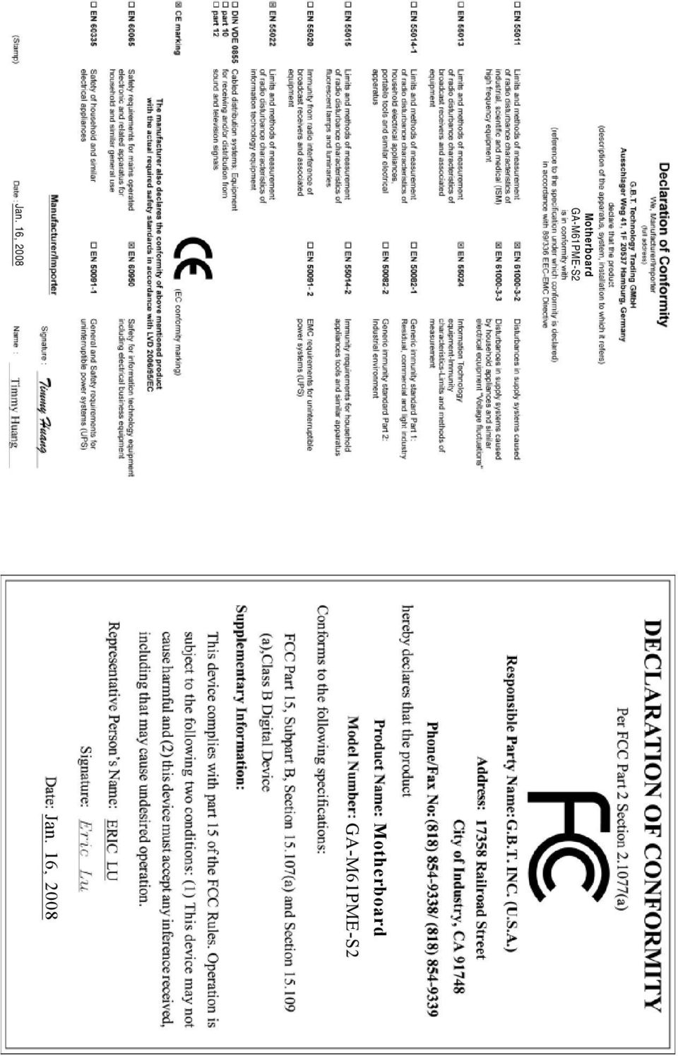
1 GA-M61PME-S2 AM2 socket motherboard for AMD Athlon TM 64 FX processor/ AMD Athlon TM 64 X2 Dual-Core processor/ AMD Athlon TM 64 processor/amd Sempron TM processor User's Manual Rev ME-M61PMES2-2003R

2 Motherboard GA-M61PME-S2 Jan. 16, 2008 Motherboard GA-M61PME-S2 Jan. 16, 2008
3 Copyright 2008 GIGA-BYTE TECHNOLOGY CO., LTD. All rights reserved. The trademarks mentioned in this manual are legally registered to their respective owners. The logo is exclusively licensed to GIGABYTE UNITED INC. by GIGA-BYTE TECHNOLOGY CO., LTD. GIGABYTE UNITED INC. is designated by GIGA-BYTE TECHNOLOGY CO., LTD as the exclusive global distributor of GIGABYTE branded motherboards. Disclaimer Information in this manual is protected by copyright laws and is the property of GIGABYTE. Changes to the specifications and features in this manual may be made by GIGABYTE without prior notice. No part of this manual may be reproduced, copied, translated, transmitted, or published in any form or by any means without GIGABYTE's prior written permission. Documentation Classifications In order to assist in the use of this product, GIGABYTE provides the following types of documentations: For detailed product information, carefully read the User's Manual. For instructions on how to use GIGABYTE's unique features, read or download the information on/from the Support\Motherboard\Technology Guide page on our website. For product-related information, check on our website at: Identifying Your Motherboard Revision The revision number on your motherboard looks like this: "REV: X.X." For example, "REV: 1.0" means the revision of the motherboard is 1.0. Check your motherboard revision before updating motherboard BIOS, drivers, or when looking for technical information. Example:

4 Table of Contents Box Contents... 6 Optional Items... 6 GA-M61PME-S2 Motherboard Layout... 7 Block Diagram... 8 Chapter 1 Hardware Installation Installation Precautions Product Specifications Installing the CPU and CPU Cooler Installing the CPU Installing the CPU Cooler Installing the Memory Dual Channel Memory Configuration Installing a Memory Installing an Expansion Card Back Panel Connectors Internal Connectors Chapter 2 BIOS Setup Startup Screen The Main Menu Standard CMOS Features Advanced BIOS Features Integrated Peripherals Power Management Setup PnP/PCI Configurations PC Health Status Load Fail-Safe Defaults Load Optimized Defaults Set Supervisor/User Password Save & Exit Setup Exit Without Saving

5 Chapter 3 Drivers Installation Installing Chipset Drivers Software Applications Driver CD Information Hardware Information Contact Us Chapter 4 Unique Features Xpress Recovery BIOS Update Utilities Updating the BIOS with the Q-Flash Utility Updating the BIOS with Utility EasyTune Windows Vista ReadyBoost Chapter 5 Appendix Configuring SATA Hard Drive(s) Configuring the Onboard SATA Controller Making a SATA RAID Driver Diskette (For Windows XP and 2000) Installing the SATA RAID Driver and Operating System Configuring Audio Input and Output Configuring 2/4/5.1-Channel Audio Installing the S/PDIFOut Cable (Optional) Configuring Microphone Recording Using the Sound Recorder Troubleshooting Frequently Asked Questions Troubleshooting Procedure Regulatory Statements
... 70 5-1-3 Installing the SATA RAID Driver and Operating System... 71 5-2 Configuring Audio Input and Output.")
6 Box Contents GA-M61PME-S2 motherboard Motherboard driver disk (For Windows Vista) Motherboard driver disk User's Manual One IDE cable One SATA 3Gb/s cable I/O Shield The box contents above are for reference only and the actual items shall depend on product package you obtain. The box contents are subject to change without notice. The motherboard image is for reference only. Optional Items Floppy disk drive cable (Part No. 12CF1-1FD001-7*R) 2-port USB 2.0 bracket (Part No. 12CR1-1UB030-5*R) 2-port SATA power cable (Part No. 12CF1-2SERPW-0*R) S/PDIF out cable (Part No. 12CR1-1SPOUT-0*R) - 6 -
 2-port USB 2.0 bracket (Part No. 12CR1-1UB030-5*R) 2-port SATA power cable (Part No. 12CF1-2SERPW-0*R) S/PDIF out cable (Part No.")
7 GA-M61PME-S2 Motherboard Layout KB_MS ATX_12V Socket AM2 COMA ATX LPT CPU_FAN R_USB USB AUDIO VGA LAN BIOS IT8716 F_AUDIO PCIE_16 PCIE_1 CI CLR_CMOS GA-M61PME-S2 DDRII_1 DDRII_2 IDE SATAII 0 Realtek 8201CL CD_IN PCI1 PCI2 BATTERY NVIDIA GeForce 6100/ nforce 430 SATAII 1 F_USB2 F_USB1 CODEC SYS_FAN F_PANEL SPDIF_IO FDD PWR_LED - 7 -

8 Block Diagram PCIe CLK (100 MHz) AMD Socket AM2 CPU CPU CLK+/-(200 MHz) DDR2 800/667/533 MHz DIMM Dual Channel Memory Hyper Transport Bus PCI Express x16 PCI Express x1 Bus D-Sub x1 8 USB Ports PCIe CLK (100 MHz) 1 PCI Express x1 LAN RJ45 Realtek 8201CL NVIDIA GeForce 6100/ nforce SATA 3Gb/s ATA-133/100/66/33 IDE Channel PCI Bus LPC BUS BIOS Floppy IT8716 LPT Port CODEC COM Port PCI CLK (33 MHz) 2 PCI Line-Out (Front Speaker Out) MIC (Center/Subwoofer Speaker Out) Line-In (Rear Speaker Out) SPDIF Out PS/2 KB/Mouse - 8 -
 2 PCI Line-Out (Front Speaker Out) MIC (Center/Subwoofer Speaker Out) Line-In (Rear Speaker Out) SPDIF Out")
9 Chapter 1 Hardware Installation 1-1 Installation Precautions The motherboard contains numerous delicate electronic circuits and components which can become damaged as a result of electrostatic discharge (ESD). Prior to installation, carefully read the user's manual and follow these procedures: Prior to installation, do not remove or break motherboard S/N (Serial Number) sticker or warranty sticker provided by your dealer. These stickers are required for warranty validation. Always remove the AC power by unplugging the power cord from the power outlet before installing or removing the motherboard or other hardware components. When connecting hardware components to the internal connectors on the motherboard, make sure they are connected tightly and securely. When handling the motherboard, avoid touching any metal leads or connectors. It is best to wear an electrostatic discharge (ESD) wrist strap when handling electronic components such as a motherboard, CPU or memory. If you do not have an ESD wrist strap, keep your hands dry and first touch a metal object to eliminate static electricity. Prior to installing the motherboard, please have it on top of an antistatic pad or within an electrostatic shielding container. Before unplugging the power supply cable from the motherboard, make sure the power supply has been turned off. Before turning on the power, make sure the power supply voltage has been set according to the local voltage standard. Before using the product, please verify that all cables and power connectors of your hardware components are connected. To prevent damage to the motherboard, do not allow screws to come in contact with the motherboard circuit or its components. Make sure there are no leftover screws or metal components placed on the motherboard or within the computer casing. Do not place the computer system on an uneven surface. Do not place the computer system in a high-temperature environment. Turning on the computer power during the installation process can lead to damage to system components as well as physical harm to the user. If you are uncertain about any installation steps or have a problem related to the use of the product, please consult a certified computer technician Hardware Installation

10 1-2 Product Specifications CPU Support for Socket AM2 processors: AMD Athlon TM 64 FX processor/amd Athlon TM 64 X2 Dual-Core processor/ AMD Athlon TM 64 processor/amd Sempron TM processor (Go to GIGABYTE's website for the latest CPU support list.) Front Side Bus 2000 MHz FSB Chipset NVIDIA GeForce 6100/nForce 430 chipset Memory (Note 1) 2 x 1.8V DDR2 DIMM sockets supporting up to 8 GB of system memory Dual channel memory architecture Support for DDR2 800/667/533 MHz memory modules (Go to GIGABYTE's website for the latest memory support list.) Audio Realtek AL662 codec High Definition Audio 2/4/5.1-channel Support for S/PDIF Out Support for CD In LAN RTL 8201CL chip (10/100 Mbit) Expansion Slots 1 x PCI Express x16 slot 1 x PCI Express x1 slot 2 x PCI slots Storage Interface NVIDIA GeForce 6100/nForce 430 chipset: - 1 x IDE connector supporting ATA-133/100/66/33 and up to 2 IDE devices - 2 x SATA 3Gb/s connectors supporting up to 2 SATA 3Gb/s devices - Support for SATA RAID 0 and RAID 1 ite IT8716 chip: - 1 x floppy disk drive connector supporting up to 1 floppy disk drive USB Integrated in the NVIDIA GeForce 6100/nForce 430 chipset Up to 8 USB 2.0/1.1 ports (4 on the back panel, 4 via the USB brackets connected to the internal USB headers) Internal Connectors 1 x 24-pin ATX main power connector 1 x 4-pin ATX 12V power connector 1 x floppy disk drive connector 1 x IDE connector 2 x SATA 3Gb/s connectors 1 x CPU fan header 1 x system fan header 1 x front panel header 1 x front panel audio header 1 x CD In connector 1 x S/PDIF Out header 2 x USB 2.0/1.1 headers 1 x chassis intrusion header 1 x power LED header GA-M61PME-S2 Motherboard
 Audio Realtek AL662 codec High Definition Audio 2/4/5.")
11 Back Panel 1 x PS/2 keyboard port Connectors 1 x PS/2 mouse port 1 x parallel port 1 x serial port 1 x D-Sub port 4 x USB 2.0/1.1 ports 1 x RJ-45 port 3 x audio jacks (Line In/Line Out/Microphone) I/O Controller ite IT8716 chip Hardware Monitor System voltage detection CPU/System temperature detection CPU/System fan speed detection CPU/System overheating warning CPU/System fan fail warning (Note 2) CPU fan speed control BIOS 1 x 4 Mbit flash Use of licensed AWARD BIOS PnP 1.0a, DMI 2.0, SM BIOS 2.4, ACPI 1.0b Unique Features Support Support for Download Center Support for Q-Flash (Note 3) Support for EasyTune Support for Xpress Install Support for Xpress Recovery2 Support for Virtual Dual BIOS Bundled Software Norton Internet Security (OEM version) Operating System Support for Microsoft Windows Vista/XP Form Factor Micro ATX form factor; 24.4cm x 22.5cm (Note 1) Due to Windows Vista/XP 32-bit operating system limitation, when more than 4 GB of physical memory is installed, the actual memory size displayed will be less than 4 GB. (Note 2) Whether the CPU fan speed control function is supported will depend on the CPU you install. (Note 3) Available functions in Easytune may differ by motherboard model Hardware Installation
 Support for EasyTune Support for Xpress Install Support for Xpress Recovery2 Support for Virtual Dual")
12 1-3 Installing the CPU and CPU Cooler Read the following guidelines before you begin to install the CPU: Make sure that the motherboard supports the CPU. (Go to GIGABYTE's website for the latest CPU support list.) Always turn off the computer and unplug the power cord from the power outlet before installing the CPU to prevent hardware damage. Locate the pin one of the CPU. The CPU cannot be inserted if oriented incorrectly. Apply an even and thin layer of thermal grease on the surface of the CPU. Do not turn on the computer if the CPU cooler is not installed, otherwise overheating and damage of the CPU may occur. Set the CPU host frequency in accordance with the CPU specifications. It is not recommended that the system bus frequency be set beyond hardware specifications since it does not meet the standard requirements for the peripherals. If you wish to set the frequency beyond the standard specifications, please do so according to your hardware specifications including the CPU, graphics card, memory, hard drive, etc Installing the CPU A. Locate the pin one (denoted by a small triangle) of the CPU socket and the CPU. A Small Triangle Mark Denotes Pin One of the Socket AM2 CPU Socket A Small Triangle Marking Denotes CPU Pin One AM2 CPU GA-M61PME-S2 Motherboard

13 B. Follow the steps below to correctly install the CPU into the motherboard CPU socket. Before installing the CPU, make sure to turn off the computer and unplug the power cord from the power outlet to prevent damage to the CPU. CPU Socket Locking Lever Step 1: Completely lift up the CPU socket locking lever. Step 2: Align the CPU pin one (small triangle marking) with the triangle mark on the CPU socket and gently insert the CPU into the socket. Make sure that the CPU pins fit perfectly into their holes. Once the CPU is positioned into its socket, place one finger down on the middle of the CPU, lowering the locking lever and latching it into the fully locked position. Do not force the CPU into the CPU socket. The CPU cannot fit in if oriented incorrectly. Adjust the CPU orientation if this occurs Hardware Installation
 with the triangle mark on the CPU socket and gently insert the CPU into the socket. Make sure that the CPU pins fit perfectly into their holes.")
14 1-3-2 Installing the CPU Cooler Follow the steps below to correctly install the CPU cooler on the CPU. (The following procedure uses the GIGABYTE cooler as the example.) Step 1: Apply an even and thin layer of thermal grease on the surface of the installed CPU. Step 2: Place the CPU cooler on the CPU. Step 3: Hook the CPU cooler clip to the mounting lug on one side of the retention frame. On the other side, push straight down on the the CPU cooler clip to hook it to the mounting lug on the retention frame. Step 4: Turn the cam handle from the left side to the right side (as the picture above shows) to lock into place. (Refer to your CPU cooler installation manual for instructions on installing the cooler.) Step 5: Finally, attach the power connector of the CPU cooler to the CPU fan header (CPU_FAN) on the motherboard. Use extreme care when removing the CPU cooler because the thermal grease/tape between the CPU cooler and CPU may adhere to the CPU. Inadequately removing the CPU cooler may damage the CPU. GA-M61PME-S2 Motherboard

15 1-4 Installing the Memory Read the following guidelines before you begin to install the memory: Make sure that the motherboard supports the memory. It is recommended that memory of the same capacity, brand, speed, and chips be used. (Go to GIGABYTE's website for the latest memory support list.) Always turn off the computer and unplug the power cord from the power outlet before installing the memory to prevent hardware damage. Memory modules have a foolproof design. A memory module can be installed in only one direction. If you are unable to insert the memory, switch the direction Dual Channel Memory Configuration This motherboard provides two DDR2 memory sockets and supports Dual Channel Technology. After the memory is installed, the BIOS will automatically detect the specifications and capacity of the memory. Enabling Dual Channel memory mode will double the original memory bandwidth. The two DDR2 memory sockets (DDRII_1, DDRII_2) are divided into two channels as following: Channel 0: DDRII_1 Channel 1: DDRII_2 DDRII_1 DDRII_2 Due to CPU limitation, read the following guidelines before installing the memory in Dual Channel mode. 1. Dual Channel mode cannot be enabled if only one DDR2 memory module is installed. 2. When enabling Dual Channel mode with two memory modules, it is recommended that memory of the same capacity, brand, speed, and chips be used Hardware Installation

16 1-4-2 Installing a Memory Before installing a memory module, make sure to turn off the computer and unplug the power cord from the power outlet to prevent damage to the memory module. DDR2 DIMMs are not compatible to DDR DIMMs. Be sure to install DDR2 DIMMs on this motherboard. Notch DDR2 DIMM A DDR2 memory module has a notch, so it can only fit in one direction. Follow the steps below to correctly install your memory modules in the memory sockets. Step 1: Note the orientation of the memory module. Spread the retaining clips at both ends of the memory socket. Place the memory module on the socket. As indicated in the picture on the left, place your fingers on the top edge of the memory, push down on the memory and insert it vertically into the memory socket. Step 2: The clips at both ends of the socket will snap into place when the memory module is securely inserted. GA-M61PME-S2 Motherboard

17 1-5 Installing an Expansion Card Read the following guidelines before you begin to install an expansion card: Make sure the motherboard supports the expansion card. Carefully read the manual that came with your expansion card. Always turn off the computer and unplug the power cord from the power outlet before installing an expansion card to prevent hardware damage. PCI Express x16 Slot PCI Slot PCI Express x1 Slot Follow the steps below to correctly install your expansion card in the expansion slot. 1. Locate an expansion slot that supports your card. Remove the metal slot cover from the chassis back panel. 2. Align the card with the slot, and press down on the card until it is fully seated in the slot. 3. Make sure the metal contacts on the card are completely inserted into the slot. 4. Secure the card's metal bracket to the chassis back panel with a screw. 5. After installing all expansion cards, replace the chassis cover(s). 6. Turn on your computer. If necessary, go to BIOS Setup to make any required BIOS changes for your expansion card(s). 7. Install the driver provided with the expansion card in your operating system. Example: Installing and Removing a PCI Express x16 Graphics Card: Installing a Graphics Card: Gently push down on the top edge of the card until it is fully inserted into the PCI Express x16 slot. Make sure the card is securely seated in the slot and does not rock. Removing the Card: Gently push back on the lever on the slot and then lift the card straight out from the slot Hardware Installation

18 1-6 Back Panel Connectors PS/2 Keyboard and PS/2 Mouse Port Use the upper port (green) to connect a PS/2 mouse and the lower port (purple) to connect a PS/2 keyboard. Parallel Port Use the parallel port to connect devices such as a printer, scanner and etc. The parallel port is also called a printer port. Serial Port Use the serial port to connect devices such as a mouse, modem or other peripherals. D-Sub Port The D-Sub port supports a 15-pin D-Sub connector. Connect a monitor that supports D-Sub connection to this port. USB Port The USB port supports the USB 2.0/1.1 specification. Use this port for USB devices such as an USB keyboard/mouse, USB printer, USB flash drive and etc. RJ-45 LAN Port The Fast Ethernet LAN port provides Internet connection at up to 100 Mbps data rate. The following describes the states of the LAN port LEDs. Connection/ Speed LED Activity LED Connection/Speed LED: State Description Green 100 Mpbs data rate Off 10 Mpbs data rate Activity LED: State Description Blinking Data transmission or receiving is occurring Off No data transmission or receiving is occurring LAN Port When removing the cable connected to a back panel connector, first remove the cable from your device and then remove it from the motherboard. When removing the cable, pull it straight out from the connector. Do not rock it side to side to prevent an electrical short inside the cable connector. GA-M61PME-S2 Motherboard

19 Line In Jack (Blue) The default line in jack. Use this audio jack for line in devices such as an optical drive, walkman, etc. Line Out Jack (Front Speaker Out, Green) The default line out jack. Use this audio jack for a headphone or 2-channel speaker. This jack can be used to connect front speakers in a 4/5.1-channel audio configuration. Mic In Jack (Pink) The default Mic in jack. Microphones must be connected to this jack. Refer to the instructions on setting up a 2/4/5.1-channel audio configuration in Chapter 5, "Configuring 2/4/5.1-Channel Audio." Hardware Installation

20 1-7 Internal Connectors ) ATX_12V 2) ATX 3) CPU_FAN 4) SYS_FAN 5) FDD 6) IDE 7) SATAII 0 / SATAII 1 8) PWR_LED 9) BATTERY 10) F_PANEL 11) F_AUDIO 12) CD_IN 13) SPDIF_IO 14) F_USB1 / F_USB2 15) CI 16) CLR_CMOS Read the following guidelines before connecting external devices: First make sure your devices are compliant with the connectors you wish to connect. Before installing the devices, be sure to turn off the devices and your computer. Unplug the power cord from the power outlet to prevent damage to the devices. After installing the device and before turning on the computer, make sure the device cable has been securely attached to the connector on the motherboard. GA-M61PME-S2 Motherboard

21 1/2) ATX_12V/ATX (2x2 12V Power Connector and 2x12 Main Power Connector) With the use of the power connector, the power supply can supply enough stable power to all the components on the motherboard. Before connecting the power connector, first make sure the power supply is turned off and all devices are properly installed. The power connector possesses a foolproof design. Connect the power supply cable to the power connector in the correct orientation. The 12V power connector mainly supplies power to the CPU. If the 12V power connector is not connected, the computer will not start. To meet expansion requirements, it is recommended that a power supply that can withstand high power consumption be used (400W or greater). If a power supply is used that does not provide the required power, the result can lead to an unstable or unbootable system. The main power connector is compatible with power supplies with 2x10 power connectors. When using a 2x12 power supply, remove the protective cover from the main power connector on the motherboard. Do not insert the power supply cable into pins under the protective cover when using a 2x10 power supply ATX_12V ATX_12V: Pin No. Definition 1 GND 2 GND 3 +12V 4 +12V ATX: Pin No. Definition 1 3.3V 2 3.3V 3 GND 4 +5V 5 GND 6 +5V 7 GND 8 Power Good 9 5V SB(stand by +5V) V V (Only for 2x12-pin ATX) V (Only for 2x12-pin ATX) Pin No. Definition V 14-12V 15 GND 16 PS_ON(soft On/Off) 17 GND 18 GND 19 GND 20-5V 21 +5V 22 +5V 23 +5V (Only for 2x12-pin ATX) 24 GND (Only for 2x12-pin ATX) ATX Hardware Installation
22 3/4) CPU_FAN/SYS_FAN (Fan Headers) The motherboard has a 4-pin CPU fan header (CPU_FAN) and a 3-pin system fan header (SYS_FAN). Each fan header supplies a +12V power voltage and possesses a foolproof insertion design. When connecting a fan cable, be sure to connect it in the correct orientation. Most fans are designed with color-coded power connector wires. A red power connector wire indicates a positive connection and requires a +12V voltage. The black connector wire is the ground wire. The motherboard supports CPU/system fan speed control, which requires the use of a CPU/system fan with fan speed control design. For optimum heat dissipation, it is recommended that a system fan be installed inside the chassis. 1 CPU_FAN CPU_FAN: Pin No. Definition 1 GND 2 +12V 3 Sense 4 Speed Control SYS_FAN 1 SYS_FAN: Pin No. Definition 1 GND 2 +12V 3 Sense Be sure to connect fan cables to the fan headers to prevent your CPU and system from overheating. Overheating may result in damage to the CPU or the system may hang. These fan headers are not configuration jumper blocks. Do not place a jumper cap on the headers. 5) FDD (Floppy Disk Drive Connector) This connector is used to connect a floppy disk drive. The types of floppy disk drives supported are: 360 KB, 720 KB, 1.2 MB, 1.44 MB, and 2.88 MB. Before connecting a floppy disk drive, be sure to locate pin 1 of the connector and the floppy disk drive cable. The pin 1 of the cable is typically designated by a stripe of different color GA-M61PME-S2 Motherboard
23 6) IDE (IDE Connector) The IDE connector supports up to two IDE devices such as hard drives and optical drives. Before attaching the IDE cable, locate the foolproof groove on the connector. If you wish to connect two IDE devices, remember to set the jumpers and the cabling according to the role of the IDE devices (for example, master or slave). (For information about configuring master/slave settings for the IDE devices, read the instructions from the device manufacturers.) ) SATAII 0/1 (SATA 3Gb/s Connectors) The SATA connectors conform to SATA 3Gb/s standard and are compatible with SATA 1.5Gb/s standard. Each SATA connector supports a single SATA device. The NVIDIA GeForce 6100/ nforce 430 chipset controller supports RAID 0 and RAID 1. Refer to Chapter 5, "Configuring SATA Hard Drive(s)," for instructions on configuring a RAID array. SATAII SATAII1 Pin No. Definition 1 GND 2 TXP 3 TXN 4 GND 5 RXN 6 RXP 7 GND Please connect the L-shaped end of the SATA 3Gb/s cable to your SATA hard drive. A RAID 0 or RAID 1 configuration requires two hard drives Hardware Installation
24 8) PWR_LED (System Power LED Header) This header can be used to connect a system power LED on the chassis to indicate system power status. The LED is on when the system is operating. The LED keeps blinking when the system is in S1 sleep state. The LED is off when the system is in S3/S4 sleep state or powered off (S5). 1 Pin No. Definition 1 MPD+ 2 MPD- 3 MPD- System Status S0 S1 S3/S4/S5 LED On Blinking Off 9) BATTERY The battery provides power to keep the values (such as BIOS configurations, date, and time information) in the CMOS when the computer is turned off. Replace the battery when the battery voltage drops to a low level, or the CMOS values may not be accurate or may be lost. Always turn off your computer and unplug the power cord before replacing the battery. Replace the battery with an equivalent one. Danger of explosion if the battery is replaced with an incorrect model. Contact the place of purchase or local dealer if you are not able to replace the battery by yourself or uncertain about the battery model. When installing the battery, note the orientation of the positive side (+) and the negative side (-) of the battery (the positive side should face up). Used batteries must be handled in accordance with local environmental regulations. GA-M61PME-S2 Motherboard You may clear the CMOS values by removing the battery: 1. Turn off your computer and unplug the power cord. 2. Gently remove the battery from the battery holder and wait for one minute. (Or use a metal object like a screwdriver to touch the positive and negative terminals of the battery holder, making them short for 5 seconds.) 3. Replace the battery. 4. Plug in the power cord and restart your computer.
25 10) F_PANEL (Front Panel Header) Connect the power switch, reset switch, speaker and system status indicator on the chassis front panel to this header according to the pin assignments below. Note the positive and negative pins before connecting the cables. Message/Power/ Sleep LED Power Switch Speaker HD- RES+ HD+ RES- NC MSG- MSG+ SPEAK- PW- PW+ SPEAK+ Hard Drive Activity LED Reset Switch MSG (Message/Power/Sleep LED): System Status LED Connects to the power status indicator on the chassis front panel. The S0 On LED is on when the system is operating. The LED keeps blinking when S1 Blinking the system is in S1 sleep state. The LED is off when the system is in S3/S4/S5 Off S3/S4 sleep state or powered off (S5). PW (Power Switch): Connects to the power switch on the chassis front panel. You may configure the way to turn off your system using the power switch (refer to Chapter 2, "BIOS Setup," "Power Management Setup," for more information). SPEAK (Speaker): Connects to the speaker on the chassis front panel. The system reports system startup status by issuing a beep code. One single short beep will be heard if no problem is detected at system startup. If a problem is detected, the BIOS may issue beeps in different patterns to indicate the problem. Refer to Chapter 5, "Troubleshooting," for information about beep codes. HD (Hard Drive Activity LED) Connects to the hard drive activity LED on the chassis front panel. The LED is on when the hard drive is reading or writing data. RES (Reset Switch): Connects to the reset switch on the chassis front panel. Press the reset switch to restart the computer if the computer freezes and fails to perform a normal restart. NC: No connection The front panel design may differ by chassis. A front panel module mainly consists of power switch, reset switch, power LED, hard drive activity LED, speaker and etc. When connecting your chassis front panel module to this header, make sure the wire assignments and the pin assignments are matched correctly Hardware Installation
26 11) F_AUDIO (Front Panel Audio Header) The front panel audio header supports Intel High Definition audio (HD) and AC'97 audio. You may connect your chassis front panel audio module to this header. Make sure the wire assignments of the module connector match the pin assignments of the motherboard header. Incorrect connection between the module connector and the motherboard header will make the device unable to work or even damage it. For HD Front Panel Audio: For AC'97 Front Panel Audio: 10 9 Pin No. Definition Pin No. Definition 1 MIC2_L 1 MIC GND 3 MIC2_R 2 GND 3 MIC Power 4 -ACZ_DET 4 NC 5 LINE2_R 5 Line Out (R) 6 FAUDIO_JD 6 NC 7 GND 7 NC 8 No Pin 8 No Pin 9 LINE2_L 9 Line Out (L) 10 FAUDIO_JD 10 NC The front panel audio header supports HD audio by default. If your chassis provides an AC'97 front panel audio module, refer to the instructions on how to activate AC'97 functioninality via the audio software in Chapter 5, "Configuring 2/4/5.1-Channel Audio." Audio signals will be present on both of the front and back panel audio connections simultaneously. If you want to mute the back panel audio (only supported when using an HD front panel audio module), refer to Chapter 5, "Configuring 2/4/5.1/7.1-Channel Audio." Some chassis provide a front panel audio module that has separated connectors on each wire instead of a single plug. For information about connecting the front panel audio module that has different wire assignments, please contact the chassis manufacturer. 12) CD_IN (CD In Connector) You may connect the audio cable that came with your optical drive to the header. 1 Pin No. Definition 1 CD-L 2 GND 3 GND 4 CD-R GA-M61PME-S2 Motherboard
GA-P31-ES3G LGA775 socket motherboard for Intel Core TM processor family/ Intel Pentium processor family/intel Celeron processor family
 GA-P31-ES3G LGA775 socket motherboard for Intel Core TM processor family/ Intel Pentium processor family/intel Celeron processor family User's Manual Rev. 1101 12ME-P31ES3G-1101R Motherboard GA-P31-ES3G
User's Manual. Rev. 2003 12ME-MA770S3-2003R
 GA-MA770-DS3/DS3P GA-MA770-S3/S3P AM2+/AM2 socket motherboard for AMD Phenom TM FX processor/amd Phenom TM X4 processor/ AMD Phenom TM X3 processor/amd Athlon TM X2 processor/ AMD Athlon TM processor/amd
GA-EP35-DS3P LGA775 socket motherboard for Intel Core TM processor family/ Intel Pentium processor family/intel Celeron processor family
 GA-EP35-DS3P LGA775 socket motherboard for Intel Core TM processor family/ Intel Pentium processor family/intel Celeron processor family User's Manual Rev. 2101 12ME-EP35DS3P-2101R Motherboard GA-EP35-DS3P
GA-Q35M-S2 LGA775 socket motherboard for Intel Core TM processor family/ Intel Pentium processor family/intel Celeron processor family
 GA-Q35M-S2 LGA775 socket motherboard for Intel Core TM processor family/ Intel Pentium processor family/intel Celeron processor family User's Manual Rev. 1001 12ME-Q35MS2-1001R Motherboard GA-Q35M-S2 Nov.
GA-M68MT-D3P GA-M68MT-S2P
 GA-M68MT-D3P GA-M68MT-S2P User's Manual Rev. 3101 12ME-M68MT2P-3101R Motherboard GA-M68MT-D3P/GA-M68MT-S2P Dec. 31, 2010 Motherboard GA-M68MT-D3P GA-M68MT-S2P Dec. 31, 2010 Copyright 2011 GIGA-BYTE TECHNOLOGY
GA-EP45-DS3R/ GA-EP45-DS3 LGA775 socket motherboard for Intel Core TM processor family/ Intel Pentium processor family/intel Celeron processor family
 GA-EP45-DS3R/ GA-EP45-DS3 LGA775 socket motherboard for Intel Core TM processor family/ Intel Pentium processor family/intel Celeron processor family User's Manual Rev. 1004 12ME-EP45DS3R-1004R Motherboard
GA-M61P-S3 AMD Socket AM2 Processor Motherboard
 GA-M61P-S3 AMD Socket AM2 Processor Motherboard User's Manual Rev. 1002 12ME-M61PS3-1002R * The WEEE marking on the product indicates this product must not be disposed of with user's other household waste
GA-EP45-DQ6 LGA775 socket motherboard for Intel Core TM processor family/ Intel Pentium processor family/intel Celeron processor family
 GA-EP45-DQ6 LGA775 socket motherboard for Intel Core TM processor family/ Intel Pentium processor family/intel Celeron processor family User's Manual Rev. 1004 12ME-EP45DQ6-1004R Motherboard GA-EP45-DQ6
GA-M57SLI-S4 AMD Socket AM2 Processor Motherboard
 GA-M57SLI-S4 AMD Socket AM2 Processor Motherboard User's Manual Rev. 1002 12ME-M57SLI4R-1002R * The WEEE marking on the product indicates this product must not be disposed of with user's other household
GA-EG41MF-US2H LGA775 socket motherboard for Intel Core TM processor family/ Intel Pentium processor family/intel Celeron processor family
 GA-EG41MF-US2H LGA775 socket motherboard for Intel Core TM processor family/ Intel Pentium processor family/intel Celeron processor family User's Manual Rev. 1001 12ME-EG41MFU2H-1001R Motherboard GA-EG41MF-US2H
AwardBIOS Setup Utility
 AwardBIOS Setup Utility Modifications to the BIOS Setup settings should be performed by advanced users only. Setting items to incorrect values may cause your system to malfunction. Introducing BIOS Setup...2
Getting Started. Chapter 1
 Chapter 1 Getting Started Thank you for choosing the 7728 v2.x Series Micro-ATX mainboard. The 7728 v2.x Series mainboards are based on Intel H61 chipsets for optimal system efficiency. Designed to fit
GA-78LMT-S2P. User's Manual. Rev. 5101 12ME-78LMT2P-5101R
 GA-78LMT-S2P User's Manual Rev. 5101 12ME-78LMT2P-5101R Motherboard GA-78LMT-S2P Sept. 14, 2012 Motherboard GA-78LMT-S2P Sept. 14, 2012 Copyright 2012 GIGA-BYTE TECHNOLOGY CO., LTD. All rights reserved.
GA-H55M-S2. User's Manual
 GA-H55M-S2 LGA1156 socket motherboard for Intel Core i7 processors/intel Core i5 processors/intel Core i3 processors/intel Pentium processors User's Manual Rev. 1301 12ME-H55MS2-1301R Motherboard GA-H55M-S2
GA-H67MA-UD2H. User's Manual
 GA-H67MA-UD2H LGA1155 socket motherboard for Intel Core i7 processors/ Intel Core i5 processors/intel Core i3 processors/ Intel Pentium processors/intel Celeron processors User's Manual Rev. 1002 12ME-H67UD2H-1002R
PTM800Pro MAINBOARD MANUAL
 PTM800Pro MAINBOARD MANUAL DOC No. : M0590040 Rev. : A0 Date : 3, 2006 Part No. : 25-13031-00 Table of Contents Chapter 1. Overview... 1-2 Package Checklist...1-3 The PTM800Pro Mainboard...1-4 Main Features...1-5
Getting Started. Chapter 1
 Chapter 1 Getting Started Thank you for choosing the 7667 v2.2 Series (MS-7667) Micro-ATX mainboard. The series mainboards are based on Intel P67 chipsets for optimal system efficiency. Designed to fit
English. Configuring SATA Hard Drive(s)
") Configuring SATA Hard Drive(s) To configure SATA hard drive(s), follow the steps below: (1) Install SATA hard drive(s) in your system. (2) Configure SATA controller mode and boot sequence in BIOS Setup.
Configuring SATA Hard Drive(s) To configure SATA hard drive(s), follow the steps below: (1) Install SATA hard drive(s) in your system. (2) Configure SATA controller mode and boot sequence in BIOS Setup.
GA-MA785GT-UD3H. User's Manual. AM3 socket motherboard for AMD Phenom II processor/amd Athlon II processor. Rev. 1002 12ME-MA785T3-1002R
 GA-MA785GT-UD3H AM3 socket motherboard for AMD Phenom II processor/amd Athlon II processor User's Manual Rev. 1002 12ME-MA785T3-1002R Motherboard GA-MA785GT-UD3H Jul. 8, 2009 Motherboard GA-MA785GT-UD3H
Electronic Emission Notices
 1 Electronic Emission Notices Federal Communications Commission (FCC) Statement This equipment has been tested and found to comply with the limits for a Class B digital device, pursuant to Part 15 of FCC
GA-945PL-S3 Intel Core TM 2 Extreme / Core TM 2 Duo Intel Pentium D / Pentium 4 LGA775 Processor Motherboard
 GA-945PL-S3 Intel Core TM 2 Extreme / Core TM 2 Duo Intel Pentium D / Pentium 4 LGA775 Processor Motherboard User's Manual Rev. 1001 12ME-945PLS3-1001R * The WEEE marking on the product indicates this
AP480-S Motherboard layout reference Contents
 AP80-S Motherboard layout reference Contents Specifications summary Motherboard layout Rear panel connectors Function selectors Internal connectors JUL 2008 Specifications summary CPU Chipset Front Side
GA-880GM-D2H. User's Manual. Rev. 4001 12ME-880GD2H-4001R
 GA-880GM-D2H User's Manual Rev. 4001 12ME-880GD2H-4001R Motherboard GA-880GM-D2H Sept. 9, 2011 Motherboard GA-880GM-D2H Sept. 9, 2011 Copyright 2011 GIGA-BYTE TECHNOLOGY CO., LTD. All rights reserved.
GA-H61M-S1. User's Manual. Rev. 2101
 GA-H61M-S1 User's Manual Rev. 2101 Motherboard GA-H61M-S1 Mar. 9, 2012 Motherboard GA-H61M-S1 Mar. 9, 2012 Copyright 2012 GIGA-BYTE TECHNOLOGY CO., LTD. All rights reserved. The trademarks mentioned in
GA-945GZM-S2 (rev. 2.1) Intel Core TM 2 Extreme dual-core / Core TM 2 Duo / Intel Pentium D / Pentium 4 / Celeron D LGA775 Processor Motherboard
 Intel Core TM 2 Extreme dual-core / Core TM 2 Duo / Intel Pentium D / Pentium 4 / Celeron D LGA775 Processor Motherboard") GA-945GZM-S2 (rev. 2.1) Intel Core TM 2 Extreme dual-core / Core TM 2 Duo / Intel Pentium D / Pentium 4 / Celeron D LGA775 Processor Motherboard User's Manual Rev. 2101 12ME-945GZMS2-2101R * The WEEE marking
GA-945GZM-S2 (rev. 2.1) Intel Core TM 2 Extreme dual-core / Core TM 2 Duo / Intel Pentium D / Pentium 4 / Celeron D LGA775 Processor Motherboard User's Manual Rev. 2101 12ME-945GZMS2-2101R * The WEEE marking
GA-K8U AMD Socket 754 Processor Motherboard
 GA-K8U AMD Socket 754 Processor Motherboard User's Manual Rev. 1002 12ME-K8U-1002 Motherboard GA-K8U Jan. 26, 2005 Motherboard GA-K8U Jan. 26, 2005 Copyright 2005 GIGA-BYTE TECHNOLOGY CO., LTD. All rights
GA-970A-DS3P. User's Manual. Rev. 1001 12ME-970AS3P-1001R
 GA-970A-DS3P User's Manual Rev. 00 2ME-970AS3P-00R Motherboard GA-970A-DS3P Motherboard GA-970A-DS3P Apr. 0, 203 Apr. 0, 203 Copyright 203 GIGA-BYTE TECHNOLOGY CO., LTD. All rights reserved. The trademarks
85MIV2 / 85MIV2-L -- Components Locations
 Chapter Specification 85MIV2 / 85MIV2-L -- Components Locations RJ45 LAN Connector for 85MIV2-L only PS/2 Peripheral Mouse (on top) Power PS/2 K/B(underside) RJ45 (on top) +2V Power USB0 (middle) USB(underside)
Computer Setup (F10) Utility Guide HP Compaq dx2200 Microtower Business PC
 Utility Guide HP Compaq dx2200 Microtower Business PC") Guide HP Compaq dx2200 Microtower Business PC Document Part Number: 413759-001 January 2006 This guide provides instructions on how to use Computer Setup. This tool is used to reconfigure and modify computer
Guide HP Compaq dx2200 Microtower Business PC Document Part Number: 413759-001 January 2006 This guide provides instructions on how to use Computer Setup. This tool is used to reconfigure and modify computer
Getting Started. Chapter 1
 Chapter 1 Getting Started Thank you for choosing the 7681 v3.2 Series (MS7681) ATX mainboard. The series mainboards are based on Intel P67 chipsets for optimal system efficiency. Designed to fit the advanced
Phoenix SecureCore TM Setup Utility
 Phoenix SecureCore TM Setup Utility Important information: We continually strive to bring you the latest and proven features and technologies. As part of our drive to continually improve our products modifications
How To Set Up Your Motherboard With A Power Supply And Power Supply On A Microtower 2.2 (Ios) With A Hard Disk Drive On A Mini Usb 2.3 (I386) With An External Hard Disk (I2)
 With A Hard Disk Drive On A Mini Usb 2.3 (I386) With An External Hard Disk (I2)") 4-1-4 Configuring SATA Hard Drive(s) To configure SATA hard drive(s), follow the steps below: (1) Install SATA hard drive(s) in your system. (2) Configure SATA controller mode and boot sequence in BIOS
4-1-4 Configuring SATA Hard Drive(s) To configure SATA hard drive(s), follow the steps below: (1) Install SATA hard drive(s) in your system. (2) Configure SATA controller mode and boot sequence in BIOS
GA-8I945GMF Intel Pentium D / Pentium 4 LGA775 Processor Motherboard
 GA-8I945GMF Intel Pentium D / Pentium 4 LGA775 Processor Motherboard User's Manual Rev. 1005 12ME-8I945GMF-1005R * The WEEE marking on the product indicates this product must not be disposed of with user's
GA-Z97X-Gaming 5. User's Manual. Rev. 1001 12ME-Z97XGM5-1001R
 GA-Z97X-Gaming 5 User's Manual Rev. 1001 12ME-Z97XGM5-1001R Motherboard GA-Z97X-Gaming 5 Mar. 26, 2014 Motherboard GA-Z97X-Gaming 5 Mar. 26, 2014 Copyright 2014 GIGA-BYTE TECHNOLOGY CO., LTD. All rights
GA-H97M-Gaming 3. User's Manual. Rev. 1001 12ME-H97MG3-1001R
 GA-H97M-Gaming 3 User's Manual Rev. 1001 12ME-H97MG3-1001R Motherboard GA-H97M-Gaming 3 Motherboard GA-H97M-Gaming 3 Apr. 25, 2014 Apr. 25, 2014 Copyright 2014 GIGA-BYTE TECHNOLOGY CO., LTD. All rights
GA-F2A88XM-DS2. User's Manual. Rev. 3001 12ME-F288MS2-3001R
 GA-F2A88XM-DS2 User's Manual Rev. 3001 12ME-F288MS2-3001R Motherboard GA-F2A88XM-DS2 Motherboard GA-F2A88XM-DS2 Aug. 30, 2013 Aug. 30, 2013 Copyright 2013 GIGA-BYTE TECHNOLOGY CO., LTD. All rights reserved.
IPMIP-GS Series Motherboard layout reference
 IPMIP-GS Series Motherboard layout reference Contents Specifications summary Motherboard layout Rear panel s Internal s This manual is meant as a general reference guide. Refer to the product itself for
Mother Board Component
 Mother Board Component Explain Introduction Mother Board Component 1.Clock Generator 2. CPU socket 3. Memory Socket Memory error checking 4. ROM Bios 5. CMOS Ram 6. Battery 7. Chipset 8. Expansion Slot
PS/2 Keyboard Connector
 PS/2 Mouse Connector SPP/EPP/ECP Parallel Port RJ45 LAN Jack (for AX45F-4DL, AX45F-4DN and AX45F-4D Max) Line-In USB 2.0 Ports Speaker Out MIC-In Realtek Gigabit LAN chip (for AX45F-4D Max and AX45F-4DL)
(AOpen reserves the right to revise all the specifications and information contained in this document which is subject to change without notice.
 (AOpen reserves the right to revise all the specifications and information contained in this document which is subject to change without notice.) PS/2 Mouse Connector USB2.0 Ports SPP/EPP/ECP Parallel
GA-Z97M-D3H GA-H97M-D3H
 GA-Z97M-D3H GA-H97M-D3H User's Manual Rev. 1001 12ME-Z97MD3H-1001R GA-Z97M-D3H GA-H97M-D3H Motherboard GA-Z97M-D3H GA-H97M-D3H Motherboard GA-Z97M-D3H GA-H97M-D3H Apr. 11, 2014 Apr. 11, 2014 Copyright
Motherboard Specifications, A8M2N-LA (Naos)
") HP Customer Care > Compaq Presario SR2010NX Desktop PC Motherboard Specifications, A8M2N-LA (Naos) Support details» Motherboard specifications table» Motherboard layout and photos» Clearing the BIOS settings»
HP Customer Care > Compaq Presario SR2010NX Desktop PC Motherboard Specifications, A8M2N-LA (Naos) Support details» Motherboard specifications table» Motherboard layout and photos» Clearing the BIOS settings»
EVGA Z97 Classified Specs and Initial Installation (Part 1)
") User Guide EVGA Z97 Classified Specs and Initial Installation (Part 1) - 1 - Table of Contents Before you Begin 3 Parts Not in the kit.4 Intentions of the kit 4 Motherboard Specifications 5 Unpacking and
User Guide EVGA Z97 Classified Specs and Initial Installation (Part 1) - 1 - Table of Contents Before you Begin 3 Parts Not in the kit.4 Intentions of the kit 4 Motherboard Specifications 5 Unpacking and
K7S8XE. User Manual. Version 1.0 Published April 2003 Copyright 2003 ASRock INC. All rights reserved.
 K7S8XE User Manual Version 1.0 Published April 2003 Copyright 2003 ASRock INC. All rights reserved. 1 Copyright Notice: No part of this manual may be reproduced, transcribed, transmitted, or translated
GA-F2A55M-DS2. User's Manual. Rev. 1001 12ME-F255MS2-1001R
 GA-F2A55M-DS2 User's Manual Rev. 1001 12ME-F255MS2-1001R Motherboard GA-F2A55M-DS2 Aug. 20, 2012 Motherboard GA-F2A55M-DS2 Aug. 20, 2012 Copyright 2012 GIGA-BYTE TECHNOLOGY CO., LTD. All rights reserved.
IPN73-BA Motherboard layout reference Contents
 IPN73-BA Motherboard layout reference Contents Specifications summary Motherboard layout Rear panel connectors Function selectors Status indicators Internal connectors February 2008 Specifications summary
M266A. User Manual. Version 3.0 Published July 2003 Copyright 2003 ASRock INC. All rights reserved.
 M266A User Manual Version 3.0 Published July 2003 Copyright 2003 ASRock INC. All rights reserved. 1 Copyright Notice: No part of this manual may be reproduced, transcribed, transmitted, or translated in
Fujitsu LifeBook S Series
 Fujitsu LifeBook S Series BIOS Guide LifeBook S Series Model: S7220 Document Date: 07/08/2008 Document Part Number: FPC58-1920-01 FUJITSU COMPUTER SYSTEMS CORPORATION 1 LifeBook S Series BIOS S Series
Upgrading and Servicing Guide
 Upgrading and Servicing Guide The only warranties for Hewlett-Packard products and services are set forth in the express statements accompanying such products and services. Nothing herein should be construed
GA-B85N Phoenix. User's Manual. Rev. 1101 12ME-B85NPHX-1101R
 GA-B85N Phoenix User's Manual Rev. 1101 12ME-B85NPHX-1101R Motherboard GA-B85N Phoenix Motherboard GA-B85N Phoenix Jan. 3, 2014 Jan. 3, 2014 Copyright 2014 GIGA-BYTE TECHNOLOGY CO., LTD. All rights reserved.
GA-J1800N-D2H. User's Manual. Rev. 1001 12ME-J180D2H-1001R
 GA-J1800N-D2H User's Manual Rev. 1001 12ME-J180D2H-1001R Motherboard GA-J1800N-D2H Motherboard GA-J1800N-D2H Jan. 3, 2014 Jan. 3, 2014 Copyright 2014 GIGA-BYTE TECHNOLOGY CO., LTD. All rights reserved.
GA-8I945P Pro/ GA-8I945P-G Intel Pentium D / Pentium 4 LGA775 Processor Motherboard
 GA-8I945P Pro/ GA-8I945P-G Intel Pentium D / Pentium 4 LGA775 Processor Motherboard User's Manual Rev. 1005 12ME-8I945PP-1005 * The WEEE marking on the product indicates this product must not be disposed
XFX Motherboard Series
 User Guide XFX Motherboard Series nforce 630i with Geforce 7150 nforce 630i with Geforce 7100 nforce 610i with Geforce 7050 with Integrated Graphics ii XFX nforce 630i/610i Motherboard Before You Begin
GA-H61M-D2H GA-H61M-D2H-USB3
 GA-H61M-D2H GA-H61M-D2H-USB3 User's Manual Rev. 1002 12ME-H61MD2H-1002R Motherboard GA-H61M-D2H/GA-H61M-D2H-USB3 Sept. 9, 2011 Motherboard GA-H61M-D2H/ GA-H61M-D2H-USB3 Sept. 9, 2011 Copyright 2011 GIGA-BYTE
GA-Z170-HD3 GA-Z170-HD3 DDR3
 GA-Z170-HD3 GA-Z170-HD3 DDR3 User's Manual Rev. 1002 12ME-Z170HD3-1002R GA-Z170-HD3 GA-Z170-HD3 DDR3 For more product details, please visit GIGABYTE's website. To reduce the impacts on global warming,
TECHNICAL MANUAL Of Intel Cedar Trail-D & NM10 Chipset Based Mini-ITX M/B for ATOM Processor
 TECHNICAL MANUAL Of Intel Cedar Trail-D & NM10 Chipset Based Mini-ITX M/B for ATOM Processor NO.G03-NC9K-F Revision: 2.0 Release date: July 17, 2012 Trademark: * Specifications and Information contained
Computer Setup (F10) Utility Guide Evo Desktop Family Evo Workstation Family
 Utility Guide Evo Desktop Family Evo Workstation Family") b Computer Setup (F10) Utility Guide Evo Desktop Family Evo Workstation Family Document Part Number: 215867-004 May 2002 This guide provides instructions on how to use Computer Setup. This tool is used
b Computer Setup (F10) Utility Guide Evo Desktop Family Evo Workstation Family Document Part Number: 215867-004 May 2002 This guide provides instructions on how to use Computer Setup. This tool is used
GA-970A-UD3P. User's Manual. Rev. 2101 12ME-970AU3P-2101R. For more product details, please visit GIGABYTE's website.
 GA-970A-UD3P User's Manual Rev. 20 2ME-970AU3P-20R For more product details, please visit GIGABYTE's website. To reduce the impacts on global warming, the packaging materials of this product are recyclable
H97M-E/CSM. Chipset. Memory. Graphic. Expansion Slots. Storage
 H97M-E/CSM Intel Socket 1150 for the 5 th /New 4 th /4 th Generation Core i7/core i5/core i3/pentium /Celeron Processors Supports Intel 22 nm CPU Supports Intel Turbo Boost Technology 2.0 * The Intel Turbo
ZOTAC ZBOX User s Manual
 ZOTAC ZBOX User s Manual No part of this manual, including the products and software described in it, may be reproduced, transmitted, transcribed, stored in a retrieval system, or translated into any language
Using GIGABYTE Notebook for the First Time
 Congratulations on your purchase of the GIGABYTE Notebook P7! This Manual will help you to get started with setting up your notebook. For more detailed information, please visit our website at http://www.gigabyte.com.
K7S8X. User Manual. Version 1.0 Published January 2003 Copyright 2003 ASRock INC. All rights reserved.
 K7S8X User Manual Version 1.0 Published January 2003 Copyright 2003 ASRock INC. All rights reserved. 1 Copyright Notice: No part of this manual may be reproduced, transcribed, transmitted, or translated
Compaq Presario Desktop Products. Upgrading and Servicing Guide
 Compaq Presario Desktop Products Upgrading and Servicing Guide The information in this document is subject to change without notice. Hewlett-Packard Company makes no warranty of any kind with regard to
Network Appliance. Model Number SCB-6971. User s Manual. User s Manual
 Network Appliance Model Number SCB-6971 Desktop AMD Geode LX800 Network Appliance with four LAN or three LAN and four switch, Mini PCI User s Manual Version 1.0 AEWIN Technologies Co., Ltd 1 Copyright
P4I45D. User Manual. Published October 2002 Copyright 2002 ASRock INC. All rights reserved.
 P4I45D User Manual Published October 2002 Copyright 2002 ASRock INC. All rights reserved. 1 Copyright Notice: No part of this manual may be reproduced, transcribed, transmitted, or translated in any language,
Chapter 1. Getting Started Getting Started
 Getting Started Chapter 1. Getting Started Getting Started Thank you for purchasing the MD-5000 M-ATX mainboard. The MD-5000 mainboard is based on SiS 648 North Bridge & 963 South Bridge chipsets for optimal
Serial ATA RAID PCI. User's Manual
 Serial ATA RAID PCI User's Manual Chapter 1 Introduction Table of Contents 1-1 Features and Benefits. 1 1-2 System Requirements. 1 Chapter 2 RAID Arrays 2-1 RAID Overview.. 2 2-1.1 RAID 0 (striping)...
XPC BIOS User Guide. For the : DS437T
 XPC BIOS User Guide For the : DS437T Shuttle XPC Installation Guide 2014 by Shuttle Inc. All Rights Reserved. Copyright No part of this publication may be reproduced, transcribed, stored in a retrieval
TS500-E5. Configuration Guide
 TS500-E5 Configuration Guide E4631 Second Edition V2 March 2009 Copyright 2009 ASUSTeK COMPUTER INC. All Rights Reserved. No part of this manual, including the products and software described in it, may
XPC Bios User Guide. For the : SZ77R5
 XPC Bios User Guide For the : SZ77R5 Shuttle XPC Installation Guide 2012 by Shuttle Inc. All Rights Reserved. Copyright No part of this publication may be reproduced, transcribed, stored in a retrieval
Table of Contents. Configuring IDE RAID Hard Drive(s) (Controller GigaRAID (IT8212))... 2
 (Controller GigaRAID (IT8212))... 2") Table of Contents Configuring IDE RAID Hard Drive(s) (Controller GigaRAID (IT8212))... 2 (1) Installing IDE hard drive(s) in your system... 2 (2) Configuring GigaRAID controller mode and boot sequence
Table of Contents Configuring IDE RAID Hard Drive(s) (Controller GigaRAID (IT8212))... 2 (1) Installing IDE hard drive(s) in your system... 2 (2) Configuring GigaRAID controller mode and boot sequence
Serial ATA ( ULi M1573)... 2
... 2") Serial ATA ( ULi M1573)... 2 (1) SATA... 2 (2) BIOS SATA... 3 (3) RAID BIOS RAID... 5 (4) SATA... 13 (5) SATA... 15 Serial ATA ( ULi M1573) SATA (1) SATA (2) BIOS SATA (3)* RAID BIOS RAID (4) SATA (5)
Serial ATA ( ULi M1573)... 2 (1) SATA... 2 (2) BIOS SATA... 3 (3) RAID BIOS RAID... 5 (4) SATA... 13 (5) SATA... 15 Serial ATA ( ULi M1573) SATA (1) SATA (2) BIOS SATA (3)* RAID BIOS RAID (4) SATA (5)
4-1-4 Serial ATA SATA. A. Intel ICH8R (1) SATA (1) SATA (2) BIOS SATA (3) RAID BIOS RAID (4) SATA (5) SATA
 SATA (1) SATA (2) BIOS SATA (3) RAID BIOS RAID (4) SATA (5) SATA") 4-1-4 Serial ATA (1) (2) BIOS (3) RAID BIOS RAID ( ) (4) (5) (a) ( RAID ) (b) (c) Windows XP 2000 (d) A. Intel ICH8R (1) ( ) ( ) RAID - 69 - (2) BIOS BIOS 1 BIOS POST (Power-On Self Test ) BIOS CMOS
4-1-4 Serial ATA (1) (2) BIOS (3) RAID BIOS RAID ( ) (4) (5) (a) ( RAID ) (b) (c) Windows XP 2000 (d) A. Intel ICH8R (1) ( ) ( ) RAID - 69 - (2) BIOS BIOS 1 BIOS POST (Power-On Self Test ) BIOS CMOS
Chapter 5 Cubix XP4 Blade Server
 Chapter 5 Cubix XP4 Blade Server Introduction Cubix designed the XP4 Blade Server to fit inside a BladeStation enclosure. The Blade Server features one or two Intel Pentium 4 Xeon processors, the Intel
Chapter 1. Getting Started Getting Started
 Getting Started Chapter 1. Getting Started Getting Started Thank you for purchasing the MD-8080 M-ATX mainboard. The MD-8080 is based on Intel 865PE & Intel ICH5 chipsets for optimal system efficiency.
EVGA X99 Classified Specs and Initial Installation (Part 1)
") User Guide EVGA X99 Classified Specs and Initial Installation (Part 1) - 1 - Table of Contents Before you Begin 3 Parts Not in the kit.4 Intentions of the kit 4 Motherboard Specifications 5 Unpacking and
User Guide EVGA X99 Classified Specs and Initial Installation (Part 1) - 1 - Table of Contents Before you Begin 3 Parts Not in the kit.4 Intentions of the kit 4 Motherboard Specifications 5 Unpacking and
System Installation. 3-1 Socket 370 Celeron/Pentium-III Processor. Installing S370 CPU. Removing CPU. Configuring System Bus
 System Installation This chapter provides you with instructions to set up your system. The additional information is enclosed to help you set up onboard PCI device and handle WDT operation in software
Taurus Super-S3 LCM. Dual-Bay RAID Storage Enclosure for two 3.5-inch Serial ATA Hard Drives. User Manual March 31, 2014 v1.2 www.akitio.
 Dual-Bay RAID Storage Enclosure for two 3.5-inch Serial ATA Hard Drives User Manual March 31, 2014 v1.2 www.akitio.com EN Table of Contents Table of Contents 1 Introduction... 1 1.1 Technical Specifications...
Chapter 1. Getting Started Getting Started
 Getting Started Chapter. Getting Started Getting Started Thank you for purchasing the MS-700 v.x Micro ATX mainboard. The MS-700 is based on VIA K8T800 North Bridge & VT837 South Bridge and provides eight
BIOS Award v6.00pg BIOS setup guidelines
 BIOS The BIOS setup, also called CMOS setup, is a crucial part of the proper setting up of a PC the BIOS (Basic Input Output System) tells the operating system the characteristics of the main basic components
BIOS Update Release Notes
 PRODUCTS: D975XBX (Standard BIOS) BIOS Update Release Notes BIOS Version 1351 August 21, 2006 BX97510J.86A.1351.2006.0821.1744 Fixed issue where operating system CD installation caused blue screen. Resolved
Z97-PRO GAMER Especificaciones
 Z97-PRO GAMER Especificaciones CPU Intel Socket 1150 for the 5 th /New 4 th /4 th Generation Core i7/core i5/core i3/pentium /Celeron Processors Supports Intel 22 nm CPU Supports Intel Turbo Boost Technology
EUCIP IT Administrator - Module 1 PC Hardware Syllabus Version 3.0
 EUCIP IT Administrator - Module 1 PC Hardware Syllabus Version 3.0 Copyright 2011 ECDL Foundation All rights reserved. No part of this publication may be reproduced in any form except as permitted by ECDL
G1.Sniper B5. User's Manual. Rev. 1001 12ME-G1SNPB5-1001R
 G.Sniper B5 User's Manual Rev. 00 2ME-GSNPB5-00R Motherboard G.Sniper B5 Motherboard G.Sniper B5 May 30, 203 May 30, 203 Copyright 203 GIGA-BYTE TECHNOLOGY CO., LTD. All rights reserved. The trademarks
IPAEL-GS. Motherboard layout reference. Contents
 IPAEL-GS Motherboard layout reference Contents Specifications summary Motherboard layout Rear panel connectors Function selectors Internal connectors Oct 2008 Specifications summary CPU Socket: Intel Socket
GA-B85-HD3. User's Manual. Rev. 1001 12ME-B85HD3-1001R
 GA-B85-HD3 User's Manual Rev. 00 2ME-B85HD3-00R Motherboard GA-B85-HD3 Motherboard GA-B85-HD3 Apr. 30, 203 Copyright Apr. 30, 203 203 GIGA-BYTE TECHNOLOGY CO., LTD. All rights reserved. The trademarks
Tyan Computer. Transport PX22. Service Engineer s Manual
 Tyan Computer Transport PX22 Service Engineer s Manual 1 Precaution To read through the user manual, check all assembly and follow setup process before any operation on this server To keep paper clips,
GA-B85M-D3H. User's Manual. Rev. 1001 12ME-B85MD3H-1001R
 GA-B85M-D3H User's Manual Rev. 00 2ME-B85MD3H-00R Motherboard GA-B85M-D3H Motherboard GA-B85M-D3H Apr. 9, 203 Apr. 9, 203 Copyright 203 GIGA-BYTE TECHNOLOGY CO., LTD. All rights reserved. The trademarks
Internal Modem Installation with Windows 95
 Internal Modem Installation with Windows 95 You will need these items from your U.S. Robotics modem box: modem phone cord Plus: a screwdriver (not included) Determining Available Resources Your U.S. Robotics
IS7 Series (IS7-G, IS7, IS7-E, IS7-E2, IS7-E2G, IS7-E2V, IS7-M, IS7-V2)
") IS7 Series (IS7-G, IS7, IS7-E, IS7-E2, IS7-E2G, IS7-E2V, IS7-M, IS7-V2) Intel Pentium 4 System Board Socket 478 User s Manual 4200-0375-11 Rev. 1.06 Copyright and Warranty Notice The information in this
IS7 Series (IS7-G, IS7, IS7-E, IS7-E2, IS7-E2G, IS7-E2V, IS7-M, IS7-V2) Intel Pentium 4 System Board Socket 478 User s Manual 4200-0375-11 Rev. 1.06 Copyright and Warranty Notice The information in this
BIOS Update Release Notes
 BIOS Update Release Notes PRODUCTS: DH61BE, DH61CR, DH61DL, DH61WW, DH61SA, DH61ZE (Standard BIOS) BIOS Version 0120 - BEH6110H.86A.0120.2013.1112.1412 Date: November 12, 2013 ME Firmware: Ignition SKU
Using GIGABYTE Notebook for the First Time
 Congratulations on your purchase of the GIGABYTE Notebook! This Manual will help you to get started with setting up your notebook. For more detailed information, please visit our website at http://www.gigabyte.com.
Motherboard P4SD-LA. ( Oxford ) User Guide
 User Guide") ( Oxford ) User Guide Motherboard Checklist Contents specifications summary... iii 1. Motherboard layout... 1 2. Central Processing Unit (CPU)... 2 3. System memory... 3 Memory configurations... 3 Installing
( Oxford ) User Guide Motherboard Checklist Contents specifications summary... iii 1. Motherboard layout... 1 2. Central Processing Unit (CPU)... 2 3. System memory... 3 Memory configurations... 3 Installing
ALiveNF5-eSATA2+ User Manual. Version 1.0 Published January 2007 Copyright 2007 ASRock INC. All rights reserved.
 ALiveNF5-eSATA2+ User Manual Version 1.0 Published January 2007 Copyright 2007 ASRock INC. All rights reserved. 1 Copyright Notice: No part of this manual may be reproduced, transcribed, transmitted, or
Technical Information Jumpers, Connectors and Memory JXM7031 (7031-xxx) MicroATX Motherboard Dual Jasper Forest Processors
 MicroATX Motherboard Dual Jasper Forest Processors") Technical Information Jumpers, Connectors and Memory JXM7031 (7031-xxx) MicroATX Motherboard Dual Jasper Forest Processors Dimension Diagram * = Pin 1 = Card Slots are on.800 centers Notes: All dimensions
Technical Information Jumpers, Connectors and Memory JXM7031 (7031-xxx) MicroATX Motherboard Dual Jasper Forest Processors Dimension Diagram * = Pin 1 = Card Slots are on.800 centers Notes: All dimensions
SB9011D All-in-one Touch POS Terminal USER MANUAL
 SB9011D All-in-one Touch POS Terminal USER MANUAL Table of Contents 1 Overview... 2 1.1 Safety Information... 2 1.2 Electromagnetic compatibility statement... 3 2 Installation Guide... 4 2.1 Appearances...
ZOTAC ZBOX User s Manual
 ZOTAC ZBOX User s Manual No part of this manual, including the products and software described in it, may be reproduced, transmitted, transcribed, stored in a retrieval system, or translated into any language
Installation Guide MAXTOR SATAII/300 INTERNAL HARD DRIVE
 Installation Guide MAXTOR SATAII/300 INTERNAL HARD DRIVE Contents Warranty Registration Information.............................. 1 Introduction.................................................. 2 Precautions................................................
FCC Information and Copyright
 FCC Information and Copyright This equipment has been tested and found to comply with the limits of a Class B digital device, pursuant to Part 5 of the FCC Rules. These limits are designed to provide reasonable
Home Theater PC Chassis
 Home Theater PC Chassis Model: HTPC 180 BA & SA Color: Black & Silver Quick Installation Guide (U.S. & Canada Only) Version 1.0 DISCLAIMER No warranty or representation, either expressed or implied, is