Timer A (0 and 1) and PWM EE3376
|
|
|
- Owen Powers
- 7 years ago
- Views:
Transcription
1 Timer A (0 and 1) and PWM EE3376

2 General Peripheral Programming Model Each peripheral has a range of addresses in the memory map peripheral has base address (i.e. 0x00A0) each register used in the peripheral has an offset from the base some registers are for control bits to enable the peripheral bits to configure specific modes of operation bits to determine level of clock division some registers are for status which is generally read-only error conditions are represented with a bit in status register completion status some registers are for data data to be transmitted is written to data registers data received can be read from data registers data measured (i.e. ADC) can be read from data registers
 can be read from data registers")
3 Pulse Width Modulation Most commonly used for motor control switching mode for efficiency with transistor drive circuit One time configuration stand alone operation Pulse Width Modulation like a poor man s version of Digital to Analog Converter take average value of square wave with variable duty cycle low power output must buffer with driving circuit for high power applications (motors, etc) can change analog value, but much slower than D/A Generates a square wave control of frequency control of duty cycle control of polarity - starts high, ends low OR starts low, ends high control of alignment left vs. center 8 independent channels on Port P (P for PWM)

4 Pulse Width Modulation 50% 75% 25% 10%

5 Pulse Width Modulation 50% selected clock counter value duty cycle period PWM frequency = F sc / (period) = 100KHz / 10 = 10 KHz PWM duty cycle = ((period duty cycle) / (period)) * 100% = ((10 5) / 10) * 100% = 50%
 / (period)) * 100% = ((10 5) / 10) *")
6 PWM Simple Design Example write to duty cycle duty cycle 8 bit compare = clksel 8 bit counter load r latch s output write to period 8 bit compare period =

7 Functions of Timers stop watch captures time of external events for instance rising edge of input pin allows for period and pulse width measurements creates output waveform rising edge programmed for specific time falling edge programmed for specific time pulse accumulations count cycles while input is asserted count the number of rising edges on input creates periodic interrupts

8 Input Capture Mode Port pin as Input TAR a b c d e f capture time of first rising edge - LAST capture time of second rising edge - NEW input pin can be programmed in variety of ways In this example, Port input interrupt is enabled Input rising edge causes interrupt which captures time on TAR TAR is recorded and compared against previous captured value LAST value is subtracted from NEW to get period of waveforms

9 Output Compare Mode (8 channels) port pin as output TAR CCR1 CCR0 Can program edges relative to time in TAR Can generate periodic interrupts with same mechanism Set OUTMODE if output is used, don t if only needing periodic interrupts.

10 Pulse Accumulation (edge based) Port pin selected as TACLK TAR Increments on every rising edge in this example Counts the number of rising edges over time For a fixed time, can calculate the average frequency

11 Pulse Accumulation (gated time) Port pin as Input TAR TAR Interrupt for rising and falling edges of port 1 One interrupt enables TAR and one disables Use other timer to measure straight time for comparison TAR0 / TAR1 is ratio of on versus off.

12

13 MSP430 User s Manual
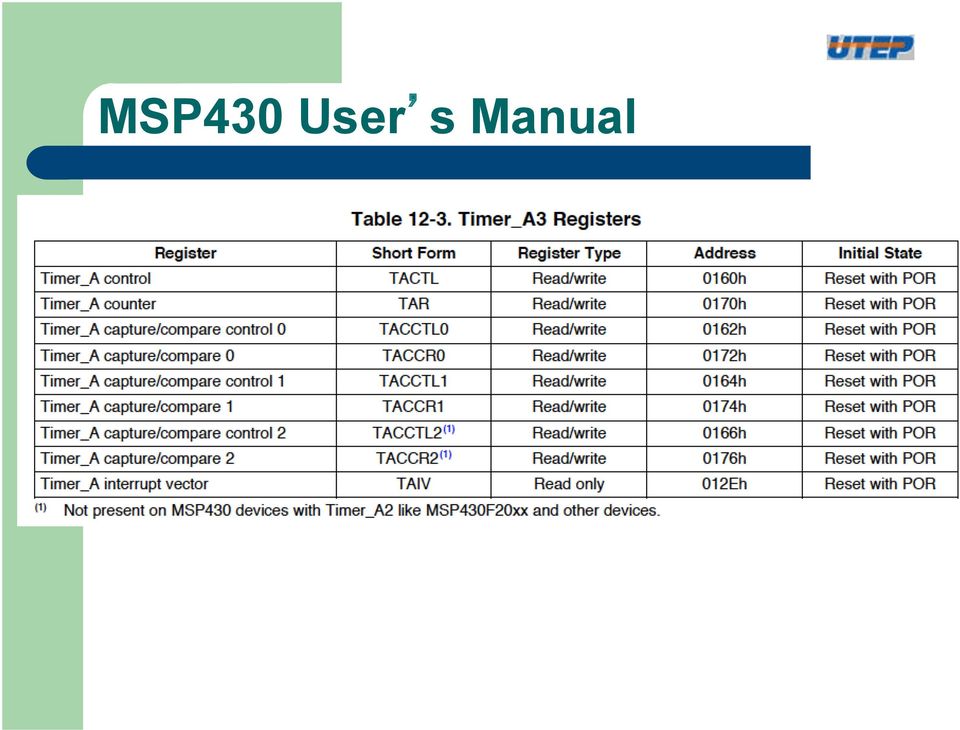
14 MSP430 User s Manual Select clock to run counter Clock divider of selected clock Counter mode Interrupt flag and enable Must read TAIV to determine which is responsible and to clear the bit. IRQ occurs if TAR == 0

15 MSP430 User s Manual In continuous mode, TAR overflow details Source Freq Divide Res Freq Period SMCLK 16MHz 1 1/16 us 240 Hz 4ms SMCLK 1MHz 1 1 us 240 Hz 66 ms SMCLK 1MHz 8 8 us 2 Hz 0.5 S ACLK 32KHz 1 31 us ½ Hz 2 S ACLK 32KHz us 1/16 Hz 16 S

16 MSP430 User s Manual Counter 3 Compare Channels

17 MSP430 User s Manual Capture mode allows TAR to be captured at a specific event example paddle wheel rotation for wind speed calculation Capture mode input select two IO possible. Gnd and Vdd are for software enabled capture. Input should always be synchronized Capture Vs. Compare mode select

18 TACCTLx continued Output Mode for Pulse Width Modulation or other modes with an output pin. See next slide for detailed examples. Not an interrupt. Flags missed capture event. If enabled in compare mode, irq if CCR == TAR If enabled in capture mode, irq after an input event and TAR is recorded in CCR.

19 One time delay Normally for centered PWM Normally for PWM Simple 50% duty wave One time delay Normally for centered PWM Normally for PWM

20 Up down mode Centered non-overlapping PWM for sophisticated motor control. Not on test in this class.

21 32 bit counter extension example If 16 bit counter is running at 1 MHz, rollover occurs every 2 16 * ( 1 / 1MHz) = 64 milliseconds By extending to 32 bits, rollover period is much longer 2 32 * ( 1 / 1MHz ) ~ 4000 seconds Set overflow interrupt service routine to increment a global variable - 16 bit TAR_extended - which represents the upper 16 bits of a 32 bit word TAR_extended- SRAM TAR= 0x
22 Note on programming MSP430 P1DIR = 0x41; P1SEL = 0x41; P1SEL2 = 0x01; // P1.0 and P1.6 to output CCR0 = 1000; //PWM Period - Freq = (SMCLK freq)/(ccr0 value) //eg,smclk = 1MHZ so 1MHZ/1000 = 1Khz is the PWM Freq CCTL1 = OUTMOD_7; //CCR1 toggle/set CCTL2 = OUTMOD_7; //CCR2 toggle/reset CCR1 = 0; //CCR1 PWM duty cycle TACTL = TASSEL_2 + MC_1; Typical programming style is to use header file abbreviations for registers and bit patterns. TACTL is the TA0CTL register at 0x160 TASSEL_2 is (2*0x0100u)) = 0x0200 unsigned picks the SMCLK MC_1 = (0x0020) picks up to CCR0 mode. TASSEL_2 MC_1 = 0x0220 which programs both the mode and clock.
23 msp430x22x4_ta_03
24 msp430x22x4_ta_03
25 msp430x22x4_ta_03
26 msp430x22x4_ta_05
27 msp430x22x4_ta_05
28 msp430x22x4_ta_05
29 msp430x22x4_ta_07
30 msp430x22x4_ta_07
31 msp430x22x4_ta_16
32 msp430x22x4_ta_16
33 msp430x22x4_ta_16
34 msp430x22x4_ta_22
35 ta_22
Pulse Width Modulation Applications
 Pulse Width Modulation Applications Lecture 21 EE 383 Microcomputers Learning Objectives What is DTMF? How to use PWM to generate DTMF? How to use PWM to control a servo motor? How to use PWM to control
AVR Timer/Counter. Prof Prabhat Ranjan DA-IICT, Gandhinagar
 AVR Timer/Counter Prof Prabhat Ranjan DA-IICT, Gandhinagar 8-bit Timer/Counter0 with PWM Single Compare Unit Counter Clear Timer on Compare Match (Auto Reload) Glitch-free, Phase Correct Pulse Width Modulator
Interfacing Analog to Digital Data Converters
 Converters In most of the cases, the PIO 8255 is used for interfacing the analog to digital converters with microprocessor. We have already studied 8255 interfacing with 8086 as an I/O port, in previous
1/22/16. You Tube Video. https://www.youtube.com/watch?v=ympzipfabyw. Definitions. Duty Cycle: on-time per period (specified in per cent)
") Definition Pulse Width Modulation (PWM) is simply a way of getting the micro-controller to manage pulsing a pin on and off at a set period and duty cycle. The LPC11U24 has four timers with four match registers
Definition Pulse Width Modulation (PWM) is simply a way of getting the micro-controller to manage pulsing a pin on and off at a set period and duty cycle. The LPC11U24 has four timers with four match registers
Using Arduino Microcontrollers to Sense DC Motor Speed and Position
 ECE480 Design Team 3 Using Arduino Microcontrollers to Sense DC Motor Speed and Position Tom Manner April 4, 2011 page 1 of 7 Table of Contents 1. Introduction ----------------------------------------------------------
Section 14. Compare/Capture/PWM (CCP)
") M Section 14. Compare/Capture/PWM (CCP) HIGHLIGHTS This section of the manual contains the following major topics: 14.1 Introduction...14-2 14.2 Control Register...14-3 14.3 Capture Mode...14-4 14.4 Compare
M Section 14. Compare/Capture/PWM (CCP) HIGHLIGHTS This section of the manual contains the following major topics: 14.1 Introduction...14-2 14.2 Control Register...14-3 14.3 Capture Mode...14-4 14.4 Compare
150127-Microprocessor & Assembly Language
 Chapter 3 Z80 Microprocessor Architecture The Z 80 is one of the most talented 8 bit microprocessors, and many microprocessor-based systems are designed around the Z80. The Z80 microprocessor needs an
ETEC 421 - Digital Controls PIC Lab 10 Pulse Width Modulation
 ETEC 421 - Digital Controls PIC Lab 10 Pulse Width Modulation Program Definition: Write a program to control the speed of a dc motor using pulse width modulation. Discussion: The speed of a dc motor is
Flexible Active Shutter Control Interface using the MC1323x
 Freescale Semiconductor Document Number: AN4353 Application Note Rev. 0, 9/2011 Flexible Active Shutter Control Interface using the MC1323x by: Dennis Lui Freescale Hong Kong 1 Introduction This application
Real-Time Clock. * Real-Time Computing, edited by Duncan A. Mellichamp, Van Nostrand Reinhold
 REAL-TIME CLOCK Real-Time Clock The device is not a clock! It does not tell time! It has nothing to do with actual or real-time! The Real-Time Clock is no more than an interval timer connected to the computer
CHAPTER 11: Flip Flops
 CHAPTER 11: Flip Flops In this chapter, you will be building the part of the circuit that controls the command sequencing. The required circuit must operate the counter and the memory chip. When the teach
AVR131: Using the AVR s High-speed PWM. Introduction. Features. AVR 8-bit Microcontrollers APPLICATION NOTE
 AVR 8-bit Microcontrollers AVR131: Using the AVR s High-speed PWM APPLICATION NOTE Introduction This application note is an introduction to the use of the high-speed Pulse Width Modulator (PWM) available
Lab 4: Pulse Width Modulation and Introduction to Simple Virtual Worlds (PWM) (PWM)
 (PWM)") 1 Lab 4: Pulse Width Modulation and Lab 4: Pulse Width Modulation and Introduction to Simple Virtual Worlds Introduction to Simple Virtual Worlds (PWM) (PWM) Virtual Spring and Virtual Wall 2 Virtual Spring
1 Lab 4: Pulse Width Modulation and Lab 4: Pulse Width Modulation and Introduction to Simple Virtual Worlds Introduction to Simple Virtual Worlds (PWM) (PWM) Virtual Spring and Virtual Wall 2 Virtual Spring
1. Learn about the 555 timer integrated circuit and applications 2. Apply the 555 timer to build an infrared (IR) transmitter and receiver
 transmitter and receiver") Electronics Exercise 2: The 555 Timer and its Applications Mechatronics Instructional Laboratory Woodruff School of Mechanical Engineering Georgia Institute of Technology Lab Director: I. Charles Ume,
Electronics Exercise 2: The 555 Timer and its Applications Mechatronics Instructional Laboratory Woodruff School of Mechanical Engineering Georgia Institute of Technology Lab Director: I. Charles Ume,
NTE2053 Integrated Circuit 8 Bit MPU Compatible A/D Converter
 NTE2053 Integrated Circuit 8 Bit MPU Compatible A/D Converter Description: The NTE2053 is a CMOS 8 bit successive approximation Analog to Digital converter in a 20 Lead DIP type package which uses a differential
Small Hardware Development and Prototyping Board for the SX28
 Project Report: Small Hardware Development and Prototyping Board for the SX28 Project Number: PR57 1. Project Description 2. Schematic Diagram 3. Physical Diagram 4. Component Layout Diagram 5. Bill of
Atmel Norway 2005. XMEGA Introduction
 Atmel Norway 005 XMEGA Introduction XMEGA XMEGA targets Leadership on Peripheral Performance Leadership in Low Power Consumption Extending AVR market reach XMEGA AVR family 44-100 pin packages 16K 51K
Digital Systems Based on Principles and Applications of Electrical Engineering/Rizzoni (McGraw Hill
 Digital Systems Based on Principles and Applications of Electrical Engineering/Rizzoni (McGraw Hill Objectives: Analyze the operation of sequential logic circuits. Understand the operation of digital counters.
Application Note AN-1187
 Application Note AN-1187 IR3230 Sensorless BLDC Motor Drive By Alex Lollio Table of Contents Application Note AN-1234... 1 Introduction... 2 Basic Working Principle... 3 Motor Control... 4 Motor Control
AN3252 Application note
 Application note Building a wave generator using STM8L-DISCOVERY Application overview This application note provides a short description of how to use the STM8L-DISCOVERY as a basic wave generator for
Hello and welcome to this training module for the STM32L4 Liquid Crystal Display (LCD) controller. This controller can be used in a wide range of
 controller. This controller can be used in a wide range of") Hello and welcome to this training module for the STM32L4 Liquid Crystal Display (LCD) controller. This controller can be used in a wide range of applications such as home appliances, medical, automotive,
Hello and welcome to this training module for the STM32L4 Liquid Crystal Display (LCD) controller. This controller can be used in a wide range of applications such as home appliances, medical, automotive,
Debouncing Switches. Mechanical switches are one of the most common interfaces to a uc.
 Mechanical switches are one of the most common interfaces to a uc. Switch inputs are asynchronous to the uc and are not electrically clean. Asynchronous inputs can be handled with a synchronizer (2 FF's).
Pulse Width Modulation
 Pulse Width Modulation Pulse width modulation (PWM) is a powerful technique for controlling analog circuits with a microprocessor's digital outputs. PWM is employed in a wide variety of applications, ranging
Eric Mitchell April 2, 2012 Application Note: Control of a 180 Servo Motor with Arduino UNO Development Board
 Eric Mitchell April 2, 2012 Application Note: Control of a 180 Servo Motor with Arduino UNO Development Board Abstract This application note is a tutorial of how to use an Arduino UNO microcontroller to
Servo Motors (SensorDAQ only) Evaluation copy. Vernier Digital Control Unit (DCU) LabQuest or LabPro power supply
 Evaluation copy. Vernier Digital Control Unit (DCU) LabQuest or LabPro power supply") Servo Motors (SensorDAQ only) Project 7 Servos are small, relatively inexpensive motors known for their ability to provide a large torque or turning force. They draw current proportional to the mechanical
Servo Motors (SensorDAQ only) Project 7 Servos are small, relatively inexpensive motors known for their ability to provide a large torque or turning force. They draw current proportional to the mechanical
Data Acquisition Module with I2C interface «I2C-FLEXEL» User s Guide
 Data Acquisition Module with I2C interface «I2C-FLEXEL» User s Guide Sensors LCD Real Time Clock/ Calendar DC Motors Buzzer LED dimming Relay control I2C-FLEXEL PS2 Keyboards Servo Motors IR Remote Control
Microcontroller for Variable Speed BLDC Fan Control System. T.C. Lun System Engineer, Freescale Semiconductor, Inc.
 Microcontroller for Variable Speed BLDC Fan Control System T.C. Lun System Engineer, Freescale Semiconductor, Inc. 1 Introduction Portable, feature rich, high-performance and compact in size are typical
MicroMag3 3-Axis Magnetic Sensor Module
 1008121 R01 April 2005 MicroMag3 3-Axis Magnetic Sensor Module General Description The MicroMag3 is an integrated 3-axis magnetic field sensing module designed to aid in evaluation and prototyping of PNI
Crazy Alarm Clock L A K S H M I M E Y Y A P P A N J A M E S K A Y E W I L L I A M D I E H L C O N G C H E N
 Crazy Alarm Clock L A K S H M I M E Y Y A P P A N J A M E S K A Y E W I L L I A M D I E H L C O N G C H E N Overview Problem: Some people hit snooze excessively every morning rather than getting out of
DEPARTMENT OF COMPUTER SCIENCE & ENGINEERING Question Bank Subject Name: EC6504 - Microprocessor & Microcontroller Year/Sem : II/IV
 DEPARTMENT OF COMPUTER SCIENCE & ENGINEERING Question Bank Subject Name: EC6504 - Microprocessor & Microcontroller Year/Sem : II/IV UNIT I THE 8086 MICROPROCESSOR 1. What is the purpose of segment registers
PART B QUESTIONS AND ANSWERS UNIT I
 PART B QUESTIONS AND ANSWERS UNIT I 1. Explain the architecture of 8085 microprocessor? Logic pin out of 8085 microprocessor Address bus: unidirectional bus, used as high order bus Data bus: bi-directional
DC Motor control Reversing
 January 2013 DC Motor control Reversing and a "Rotor" which is the rotating part. Basically there are three types of DC Motor available: - Brushed Motor - Brushless Motor - Stepper Motor DC motors Electrical
Display Board Pulse Width Modulation (PWM) Power/Speed Controller Module
 Power/Speed Controller Module") Display Board Pulse Width Modulation (PWM) Power/Speed Controller Module RS0 Microcontroller LEDs Motor Control Pushbuttons Purpose: To demonstrate an easy way of using a Freescale RS0K2 microcontroller
Display Board Pulse Width Modulation (PWM) Power/Speed Controller Module RS0 Microcontroller LEDs Motor Control Pushbuttons Purpose: To demonstrate an easy way of using a Freescale RS0K2 microcontroller
Implementing SPI Communication Between MSP430 G2452 and LTC2382-16 ADC
 Implementing SPI Communication Between MSP430 G2452 and LTC2382-16 ADC Enwei Gu Nov. 12, 2011 MCU ADC MSP430- G2452 LTC2382-16 16- bits SPI Keywords 1 Abstract This document describes and shows how to
Basic Pulse Width Modulation
 EAS 199 Fall 211 Basic Pulse Width Modulation Gerald Recktenwald v: September 16, 211 gerry@me.pdx.edu 1 Basic PWM Properties Pulse Width Modulation or PWM is a technique for supplying electrical power
DP8570A DP8570A Timer Clock Peripheral (TCP)
") DP8570A DP8570A Timer Clock Peripheral (TCP) Literature Number: SNAS557 DP8570A Timer Clock Peripheral (TCP) General Description The DP8570A is intended for use in microprocessor based systems where information
DP8570A DP8570A Timer Clock Peripheral (TCP) Literature Number: SNAS557 DP8570A Timer Clock Peripheral (TCP) General Description The DP8570A is intended for use in microprocessor based systems where information
AN4646 Application note
 Application note Peripheral interconnections on STM32F401 and STM32F411 lines Introduction On top of the highest performance and the lowest power consumption of the STM32F4 family, STM32F401/411 peripherals
Section 21. 8-bit A/D Converter
 M Section 21. Converter HIGHLIGHTS 21 Convertor This section of the manual contains the following major topics: 21.1 Introduction...21-2 21.2 Control Registers...21-3 21.3 Operation...21-5 21.4 A/D Acquisition
DAC Digital To Analog Converter
 DAC Digital To Analog Converter DAC Digital To Analog Converter Highlights XMC4000 provides two digital to analog converters. Each can output one analog value. Additional multiple analog waves can be generated
Sequential Logic: Clocks, Registers, etc.
 ENEE 245: igital Circuits & Systems Lab Lab 2 : Clocks, Registers, etc. ENEE 245: igital Circuits and Systems Laboratory Lab 2 Objectives The objectives of this laboratory are the following: To design
Serial Communications
 Serial Communications 1 Serial Communication Introduction Serial communication buses Asynchronous and synchronous communication UART block diagram UART clock requirements Programming the UARTs Operation
Experiment # 9. Clock generator circuits & Counters. Eng. Waleed Y. Mousa
 Experiment # 9 Clock generator circuits & Counters Eng. Waleed Y. Mousa 1. Objectives: 1. Understanding the principles and construction of Clock generator. 2. To be familiar with clock pulse generation
Accurate Measurement of the Mains Electricity Frequency
 Accurate Measurement of the Mains Electricity Frequency Dogan Ibrahim Near East University, Faculty of Engineering, Lefkosa, TRNC dogan@neu.edu.tr Abstract The frequency of the mains electricity supply
ARM Thumb Microcontrollers. Application Note. Software ISO 7816 I/O Line Implementation. Features. Introduction
 Software ISO 7816 I/O Line Implementation Features ISO 7816-3 compliant (direct convention) Byte reception and transmission with parity check Retransmission on error detection Automatic reception at the
CoE3DJ4 Digital Systems Design. Chapter 4: Timer operation
 CoE3DJ4 Digital Systems Design Chapter 4: Timer operation Timer There are two 16-bit timers each with four modes of operation Timers are used for (a) interval timing, (b) event counting or (c) baud rate
Pulse Width Modulation (PWM) LED Dimmer Circuit. Using a 555 Timer Chip
 LED Dimmer Circuit. Using a 555 Timer Chip") Pulse Width Modulation (PWM) LED Dimmer Circuit Using a 555 Timer Chip Goals of Experiment Demonstrate the operation of a simple PWM circuit that can be used to adjust the intensity of a green LED by varying
Pulse Width Modulation (PWM) LED Dimmer Circuit Using a 555 Timer Chip Goals of Experiment Demonstrate the operation of a simple PWM circuit that can be used to adjust the intensity of a green LED by varying
AVR151: Setup and Use of the SPI. Introduction. Features. Atmel AVR 8-bit Microcontroller APPLICATION NOTE
 Atmel AVR 8-bit Microcontroller AVR151: Setup and Use of the SPI APPLICATION NOTE Introduction This application note describes how to set up and use the on-chip Serial Peripheral Interface (SPI) of the
Lesson-16: Real time clock DEVICES AND COMMUNICATION BUSES FOR DEVICES NETWORK
 DEVICES AND COMMUNICATION BUSES FOR DEVICES NETWORK Lesson-16: Real time clock 1 Real Time Clock (RTC) A clock, which is based on the interrupts at preset intervals. An interrupt service routine executes
Microtronics technologies Mobile: 99707 90092
 For more Project details visit: http://www.projectsof8051.com/rfid-based-attendance-management-system/ Code Project Title 1500 RFid Based Attendance System Synopsis for RFid Based Attendance System 1.
HT46R14A Single Phase AC Induction Motor Frequency Converter Application
 HT46R14A Single Phase AC Induction Motor Frequency Converter Application D/N:HA0095E Introductions Initially the main reason for using frequency conversion technology was for speed control, however to
8254 PROGRAMMABLE INTERVAL TIMER
 PROGRAMMABLE INTERVAL TIMER Y Y Y Compatible with All Intel and Most Other Microprocessors Handles Inputs from DC to 10 MHz 8 MHz 8254 10 MHz 8254-2 Status Read-Back Command Y Y Y Y Y Six Programmable
Hello, and welcome to this presentation of the STM32L4 reset and clock controller.
 Hello, and welcome to this presentation of the STM32L4 reset and clock controller. 1 The STM32L4 reset and clock controller manages system and peripheral clocks. STM32L4 devices embed three internal oscillators,
MODULE BOUSSOLE ÉLECTRONIQUE CMPS03 Référence : 0660-3
 MODULE BOUSSOLE ÉLECTRONIQUE CMPS03 Référence : 0660-3 CMPS03 Magnetic Compass. Voltage : 5v only required Current : 20mA Typ. Resolution : 0.1 Degree Accuracy : 3-4 degrees approx. after calibration Output
Pmod peripheral modules are powered by the host via the interface s power and ground pins.
 Digilent Pmod Interface Specification Revision: November 20, 2011 1300 NE Henley Court, Suite 3 Pullman, WA 99163 (509) 334 6306 Voice (509) 334 6300 Fax Introduction The Digilent Pmod interface is used
US-Key New generation of High performances Ultrasonic device
 US-Key New generation of High performances Ultrasonic device US-Key connected to a laptop computer US-Key Ultrasound device single channel Features USB2 High Speed connection Ultralow noise preamplifier
8-bit Microcontroller. Application Note. AVR134: Real-Time Clock (RTC) using the Asynchronous Timer. Features. Theory of Operation.
 using the Asynchronous Timer. Features. Theory of Operation.") AVR134: Real-Time Clock (RTC) using the Asynchronous Timer Features Real-Time Clock with Very Low Power Consumption (4µA @ 3.3V) Very Low Cost Solution Adjustable Prescaler to Adjust Precision Counts Time,
AVR134: Real-Time Clock (RTC) using the Asynchronous Timer Features Real-Time Clock with Very Low Power Consumption (4µA @ 3.3V) Very Low Cost Solution Adjustable Prescaler to Adjust Precision Counts Time,
Decimal Number (base 10) Binary Number (base 2)
 Binary Number (base 2)") LECTURE 5. BINARY COUNTER Before starting with counters there is some vital information that needs to be understood. The most important is the fact that since the outputs of a digital chip can only be
LECTURE 5. BINARY COUNTER Before starting with counters there is some vital information that needs to be understood. The most important is the fact that since the outputs of a digital chip can only be
DS1104 R&D Controller Board
 DS1104 R&D Controller Board Cost-effective system for controller development Highlights Single-board system with real-time hardware and comprehensive I/O Cost-effective PCI hardware for use in PCs Application
Adding Heart to Your Technology
 RMCM-01 Heart Rate Receiver Component Product code #: 39025074 KEY FEATURES High Filtering Unit Designed to work well on constant noise fields SMD component: To be installed as a standard component to
Signal Processing in So.ware and Electric Field Sensing
 Signal Processing in So.ware and Electric Field Sensing CSE 466: So.ware for Embedded Systems Winter 2009 B. Mayton University of Washington CSE & Intel Research SeaMle CSE
Lab Experiment 1: The LPC 2148 Education Board
 Lab Experiment 1: The LPC 2148 Education Board 1 Introduction The aim of this course ECE 425L is to help you understand and utilize the functionalities of ARM7TDMI LPC2148 microcontroller. To do that,
M25P05-A. 512-Kbit, serial flash memory, 50 MHz SPI bus interface. Features
 512-Kbit, serial flash memory, 50 MHz SPI bus interface Features 512 Kbits of flash memory Page program (up to 256 bytes) in 1.4 ms (typical) Sector erase (256 Kbits) in 0.65 s (typical) Bulk erase (512
LADDER LOGIC/ FLOWCHART PROGRAMMING DIFFERENCES AND EXAMPLES
 page 1/10 This document is designed as a quick-start primer to assist industrial automation programmers who are familiar with PLCs and Relay Ladder Logic programming to better understand the corresponding
A 5 Degree Feedback Control Robotic Arm (Haptic Arm)
") A 5 Degree Feedback Control Robotic Arm (Haptic Arm) 1 Prof. Sheetal Nirve, 2 Mr.Abhilash Patil, 3 Mr.Shailesh Patil, 4 Mr.Vishal Raut Abstract: Haptics is the science of applying touch sensation and control
A 5 Degree Feedback Control Robotic Arm (Haptic Arm) 1 Prof. Sheetal Nirve, 2 Mr.Abhilash Patil, 3 Mr.Shailesh Patil, 4 Mr.Vishal Raut Abstract: Haptics is the science of applying touch sensation and control
Analog to Digital Conversion of Sound with the MSP430F2013
 Analog to Digital Conversion of Sound with the MSP430F2013 Christopher Johnson 4/2/2010 Abstract Several modern-day applications require that analog signals be converted to digital signals in order to
Interfacing To Alphanumeric Displays
 Interfacing To Alphanumeric Displays To give directions or data values to users, many microprocessor-controlled instruments and machines need to display letters of the alphabet and numbers. In systems
Module 3: Floyd, Digital Fundamental
 Module 3: Lecturer : Yongsheng Gao Room : Tech - 3.25 Email : yongsheng.gao@griffith.edu.au Structure : 6 lectures 1 Tutorial Assessment: 1 Laboratory (5%) 1 Test (20%) Textbook : Floyd, Digital Fundamental
AC 2007-2485: PRACTICAL DESIGN PROJECTS UTILIZING COMPLEX PROGRAMMABLE LOGIC DEVICES (CPLD)
") AC 2007-2485: PRACTICAL DESIGN PROJECTS UTILIZING COMPLEX PROGRAMMABLE LOGIC DEVICES (CPLD) Samuel Lakeou, University of the District of Columbia Samuel Lakeou received a BSEE (1974) and a MSEE (1976)
AC 2007-2485: PRACTICAL DESIGN PROJECTS UTILIZING COMPLEX PROGRAMMABLE LOGIC DEVICES (CPLD) Samuel Lakeou, University of the District of Columbia Samuel Lakeou received a BSEE (1974) and a MSEE (1976)
Single Phase Two-Channel Interleaved PFC Operating in CrM
 Freescale Semiconductor Application Note Document Number: AN4836 Rev. 0, 12/2013 Single Phase Two-Channel Interleaved PFC Operating in CrM Using the MC56F82xxx Family of Digital Signal Controllers by Freescale
3-Digit Counter and Display
 ECE 2B Winter 2007 Lab #7 7 3-Digit Counter and Display This final lab brings together much of what we have done in our lab experiments this quarter to construct a simple tachometer circuit for measuring
8051 hardware summary
 8051 hardware summary 8051 block diagram 8051 pinouts + 5V ports port 0 port 1 port 2 port 3 : dual-purpose (general-purpose, external memory address and data) : dedicated (interfacing to external devices)
Chapter 6: From Digital-to-Analog and Back Again
 Chapter 6: From Digital-to-Analog and Back Again Overview Often the information you want to capture in an experiment originates in the laboratory as an analog voltage or a current. Sometimes you want to
Counters. Present State Next State A B A B 0 0 0 1 0 1 1 0 1 0 1 1 1 1 0 0
 ounter ounters ounters are a specific type of sequential circuit. Like registers, the state, or the flip-flop values themselves, serves as the output. The output value increases by one on each clock cycle.
Application Note: AN00103 Enabling DSD256 in the USB Audio 2.0 Device Reference Design Software
 Application Note: AN00103 Enabling DSD256 in the USB Audio 2.0 Device Reference Design Software The XMOS USB Audio 2.0 device software reference design software supports stereo DSD64 and DSD128 streaming
Keil C51 Cross Compiler
 Keil C51 Cross Compiler ANSI C Compiler Generates fast compact code for the 8051 and it s derivatives Advantages of C over Assembler Do not need to know the microcontroller instruction set Register allocation
Software Manual RS232 Laser Merge Module. Document # SU-256521-09 Rev A
 Laser Merge Module Document # SU-256521-09 Rev A The information presented in this document is proprietary to Spectral Applied Research Inc. and cannot be used for any purpose other than that for which
ETEC 2301 Programmable Logic Devices. Chapter 10 Counters. Shawnee State University Department of Industrial and Engineering Technologies
 ETEC 2301 Programmable Logic Devices Chapter 10 Counters Shawnee State University Department of Industrial and Engineering Technologies Copyright 2007 by Janna B. Gallaher Asynchronous Counter Operation
Semiconductor MSM82C43
 Semiconductor MSM8C3 Semiconductor MSM8C3 INPUT/OUTPUT PORT EXPANDER GENERAL DESCRIPTION The MSM8C3 is an input/output port expander device based on CMOS technology and designed to operate at low power
ECONseries Low Cost USB DAQ
 ECONseries Low Cost USB Data Acquisition Modules ECONseries Low Cost USB DAQ The ECONseries is a flexible yet economical series of multifunction data acquisition modules. You choose the number of analog
Monitoring of Intravenous Drip Rate
 Monitoring of Intravenous Drip Rate Vidyadhar V. Kamble, Prem C. Pandey, Chandrashekar P. Gadgil, and Dinesh S. Choudhary Abstract A drip rate meter, for monitoring intravenous infusion, is developed using
Serial Communications (Chapter 10) RS232, SPI, I2C
 RS232, SPI, I2C") Serial Communications (Chapter 10) RS232, SPI, I2C Thesimplest is parallel One way Communications There may be mechanism for peripheral to get attention of μc(i.e., interrupt, or poll) μc Multiple (8 typically)
Serial Communications (Chapter 10) RS232, SPI, I2C Thesimplest is parallel One way Communications There may be mechanism for peripheral to get attention of μc(i.e., interrupt, or poll) μc Multiple (8 typically)
TAR25 audio recorder. User manual Version 1.03
 TAR25 audio recorder User manual Version 1.03 This recorder is the smallest audio recorder available on a market. You can record any audio or human conversation in high quality and store all into the internal
FG085 08501, 08501K, 08502K, 08503, 08503K, 08504K
 FG085 minidds Function Generator Manual of Operation Applicable Models: 08501, 08501K, 08502K, 08503, 08503K, 08504K Applicable Firmware Version: 1 ) 113-08501-130 or later (for U5) 2 ) 113-08502-050 or
HD44780U (LCD-II) (Dot Matrix Liquid Crystal Display Controller/Driver)
 (Dot Matrix Liquid Crystal Display Controller/Driver)") HD4478U (LCD-II) (Dot Matrix Liquid Crystal Display Controller/Driver) Description The HD4478U dot-matrix liquid crystal display controller and driver LSI displays alphanumerics, Japanese kana characters,
HD4478U (LCD-II) (Dot Matrix Liquid Crystal Display Controller/Driver) Description The HD4478U dot-matrix liquid crystal display controller and driver LSI displays alphanumerics, Japanese kana characters,
A Digital Timer Implementation using 7 Segment Displays
 A Digital Timer Implementation using 7 Segment Displays Group Members: Tiffany Sham u2548168 Michael Couchman u4111670 Simon Oseineks u2566139 Caitlyn Young u4233209 Subject: ENGN3227 - Analogue Electronics
A Description of Pulse Width Modulation Motor Control for Model Locomotives
 A Description of Pulse Width Modulation Motor Control for Model Locomotives Covers all NCE N-Scale through O-Scale decoder models with version numbers from 1.0-2.9 NCE Corp. 1900 Empire Blvd. Suite 303
GDM1602A SPECIFICATIONS OF LCD MODULE. Features. Outline dimension
 SPECIFICATIONS OF LCD MODULE Features 1. 5x8 dots 2. Built-in controller (S6A0069 or Equivalent) 3. Power supply: Type 5V 4. 1/16 duty cycle 5. LED backlight 6. N.V. option Outline dimension Absolute maximum
Key Words Student Paper, School of Professional Studies
 Motor Speed Sensing with PIC Microcontroller Brandon Upchurch, Olivet Nazarene University Faculty Advisor: Dr. Rodney Korthals, Olivet Nazarene University Student Paper Abstract A system was designed and
css Custom Silicon Solutions, Inc.
 css Custom Silicon Solutions, Inc. CSS555(C) CSS555/ PART DESCRIPTION The CSS555 is a micro-power version of the popular 555 Timer IC. It is pin-for-pin compatible with the standard 555 timer and features
[F/T] [5] [KHz] [AMP] [3] [V] 4 ) To set DC offset to -2.5V press the following keys [OFS] [+/-] [2] [.] [5] [V]
![[F/T] [5] [KHz] [AMP] [3] [V] 4 ) To set DC offset to -2.5V press the following keys [OFS] [+/-] [2] [.] [5] [V]](/thumbs/40/20623504.jpg "[F/T] [5] [KHz] [AMP] [3] [V] 4 ) To set DC offset to -2.5V press the following keys [OFS] [+/-] [2] [.] [5] [V]") FG085 minidds Function Generator Manual of Operation Applicable Models: 08501, 08501K, 08502K, 08503, 08503K Applicable Firmware Version: 1 ) 113-08501-100 or later (for U5) 2 ) 113-08502-030 or later
FG085 minidds Function Generator Manual of Operation Applicable Models: 08501, 08501K, 08502K, 08503, 08503K Applicable Firmware Version: 1 ) 113-08501-100 or later (for U5) 2 ) 113-08502-030 or later
Having read this workbook you should be able to: recognise the arrangement of NAND gates used to form an S-R flip-flop.
 Objectives Having read this workbook you should be able to: recognise the arrangement of NAND gates used to form an S-R flip-flop. describe how such a flip-flop can be SET and RESET. describe the disadvantage
Section 23. 10-bit A/D Converter
 M Section 23. A/D Converter HIGHLIGHTS This section of the manual contains the following major topics: 23.1 Introduction...23-2 23.2 Control Register...23-3 23.3 Operation...23-5 23.4 A/D Acquisition Requirements...23-6
ADS9850 Signal Generator Module
 1. Introduction ADS9850 Signal Generator Module This module described here is based on ADS9850, a CMOS, 125MHz, and Complete DDS Synthesizer. The AD9850 is a highly integrated device that uses advanced
LEVERAGING FPGA AND CPLD DIGITAL LOGIC TO IMPLEMENT ANALOG TO DIGITAL CONVERTERS
 LEVERAGING FPGA AND CPLD DIGITAL LOGIC TO IMPLEMENT ANALOG TO DIGITAL CONVERTERS March 2010 Lattice Semiconductor 5555 Northeast Moore Ct. Hillsboro, Oregon 97124 USA Telephone: (503) 268-8000 www.latticesemi.com
Microcontroller Basics A microcontroller is a small, low-cost computer-on-a-chip which usually includes:
 Microcontroller Basics A microcontroller is a small, low-cost computer-on-a-chip which usually includes: An 8 or 16 bit microprocessor (CPU). A small amount of RAM. Programmable ROM and/or flash memory.
Servo Info and Centering
 Info and Centering A servo is a mechanical motorized device that can be instructed to move the output shaft attached to a servo wheel or arm to a specified position. Inside the servo box is a DC motor
Introduction the Serial Communications Huang Sections 9.2, 10.2 SCI Block User Guide SPI Block User Guide
 Introduction the Serial Communications Huang Sections 9.2, 10.2 SCI Block User Guide SPI Block User Guide Parallel Data Transfer Suppose you need to transfer data from one HCS12 to another. How can you
AN1229. Class B Safety Software Library for PIC MCUs and dspic DSCs OVERVIEW OF THE IEC 60730 STANDARD INTRODUCTION
 Class B Safety Software Library for PIC MCUs and dspic DSCs AN1229 Authors: Veena Kudva & Adrian Aur Microchip Technology Inc. OVERVIEW OF THE IEC 60730 STANDARD INTRODUCTION This application note describes