FLASHING ADVANCE WARNING LIGHTS. Background
|
|
|
- Augustus Hicks
- 7 years ago
- Views:
Transcription
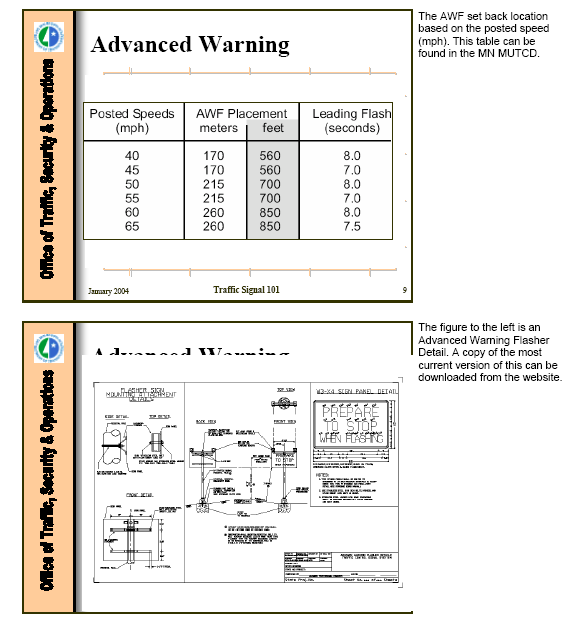
1 FLASHING ADVANCE WARNING LIGHTS Background These devices go by several names but in general refer to a sign that has flashing lights on it that come on when the signal ahead is going to turn from green to yellow and then stay flashing until the green comes on again. The messages on the sign vary, with Prepare to Stop When Flashing a common one. The device is often employed as a countermeasure to several problems, all of which are somewhat interrelated. It may be used as a method of providing dilemma zone protection, especially at high-speed approaches. It can also be used to alert motorists to a signalized intersection that has limited sight distance, has heavy truck traffic, is located on a downgrade, is at an unexpected location, or a combination of these. Finally, it can be used as a countermeasure to reduce red-light running. There have been several studies that address the effectiveness of these devices and at least two state DOTs have guidelines for their deployment. Following are excerpts from three of the documents that summarize the results of these studies and reflect the key findings of the literature. The guidelines found in the literature review are given after these three excerpts. Excerpt No. 1 (see references at end of this section) Source: Dilemma Zone Protection with Advance Detection and Active Warning Signs. Patrick T. McCoy and Geza Pesti Active (Flashing) Advance Warning Signs for Dilemma Zone Protection Common methods of providing dilemma zone protection on high-speed approaches to signalized intersections are advance detection and active advance warning signs. In the case of advance detection, a series of detectors are placed on the intersection approach so that approaching vehicles are able to extend the green as they travel through the dilemma zone and prevent the onset of yellow while they are in the dilemma zone. Studies in Kentucky (3), Texas (4), and California (5) have found that advance detection is effective in reducing crashes and traffic conflicts on high-speed approaches to signalized intersections. However, some (1,2) have noted the long allowable gaps provided by advance detection designs increase the frequency of reaching the maximum green interval at which point the green is terminated and the yellow is displayed immediately without regard to the presence of vehicles in the dilemma zone. The termination of green in this manner is referred to as max-out. Thus, when max-out occurs, the dilemma zone protection is lost. This becomes a greater problem as traffic volumes on the approach increase. Active advance warning signs consist of warning signs equipped with one or more yellow flashing beacons. The signs typically used are warning signs with the legend PREPARE TO STOP WHEN FLASHING or the symbolic SIGNAL AHEAD warning sign. The signs are interconnected with the traffic signals at the intersections so that the flashers are activated at a predetermined time before the end of the green interval. This time is based on the distance from the sign to the stop line and the prevailing approach speed, or the posted speed limit. In this way, the signs are intended to reduce the indecision of drivers and the variability in their behavior by providing them with additional information about the status of the traffic signal ahead. A

2 2 synthesis of practice (6) related to accident countermeasures at high-speed signalized intersections concluded that active advance warning signs are generally believed to be most effective at intersections hidden from the view of approaching traffic and on expressways where traffic signals are least expected. An evaluation of the accident experience at isolated high-speed signalized intersections in California (5), indicated that active advance warning signs on highspeed signalized intersection approaches are effective in reducing total, rear end, right-angle, and nighttime accidents. However, the results of a before-and-after study of accidents at high-speed signalized intersections in Minnesota (7) were mixed. Some intersections experienced reductions in total, right angle, and rear end accident rates after the installation of active advance warning signs and others did not. Inconsistent results were also found by a study of high-speed signalized intersections in British Columbia, Canada (8). An average reduction of 25 percent was found, but the accident reduction among the 25 study sites ranged from -44 to +65 percent. In comparing the 25 sites with active advance warning signs to 81 high-speed signalized intersections without active advance warning signs, it was concluded that active advance warning signs were effective in reducing the frequency and severity of accidents when the major and minor road ADTs were above 15,000 and 3,000, respectively. Traffic conflict studies (7) of active advance warning signs conducted in Minnesota found the lowest rates of red-light running violations at locations with active advance warning signs. Similarly, an Ohio study (9) also found fewer red-light running conflicts on high-speed approaches to signalized intersections with active advance warning signs. In addition, these studies revealed that drivers accelerated at the onset of yellow, but drivers decelerated at the beginning of the dilemma zone when the beacons were flashing and the signal indication was green. Nebraska Experience Conventional advance detection designs have not been effective at some intersections on the state highway system in Nebraska. Therefore, the NDOR developed a new design that includes the activation of flashing beacons on advance warning signs before the onset of yellow, advising drivers to be prepared to stop. Comments about the new design received by the NDOR from drivers, especially truck drivers, have been very favorable. However, there is some anecdotal evidence that suggests that the novelty effects of the design may have accounted for its initial success and its effectiveness may diminish over time. In addition, the results of studies conducted by other states (7,9) and the Federal Highway Administration (10) recommend against such use of active advance warning signs, because they were found to encourage drivers to accelerate at the onset of yellow in an attempt to enter the intersection before the onset of red. In 1999, there were five signalized intersections where the NDOR had replaced the conventional design with the new design. In light of the anecdotal evidence and previous research, it was not clear whether or not the conventional designs at other intersections should also be replaced. If the new design does not improve dilemma zone protection, a decision to replace the existing systems would be counterproductive, waste highway funds, and possibly increase the NDOR s exposure to tort liability claims. On the other hand, if the new design does improve dilemma zone protection, a decision not to replace the existing systems would not be in the best interests of highway safety.

3 3 References for Excerpt No J.A. Bonneson and P.T. McCoy. Manual of Traffic Detector Design. 1st Edition. Civil Engineering Department, University of Nebraska-Lincoln, Lincoln, NE P.S. Parsonson. Signal Timing Improvement Practices. National Cooperative Highway Research Program Synthesis of Highway Practice 172. Transportation Research Board, National Research Council, Washington, DC. February C.V. Zegeer and R.C. Deen. Green-Extension Systems at High-Speed Intersections, ITE Journal. November pp C. Wu, C.E. Lee, R.B. Machemehl, and J. Wright. Effects of Multiple-Point Detectors on Delay and Accidents, Transportation Research Record 881. Transportation Research Board, National Research Council, Washington, DC pp A.R. Gibby, S.P. Washington, and T.C. Ferrara. Evaluation of High-Speed Isolated Intersections in California, Transportation Research Record Transportation Research Board, National Research Council, Washington, DC pp R.W. Eck and Z.A. Sabra. Accident Countermeasures at High-Speed Signalized Intersections: Synthesis of Practice. Department of Civil Engineering, West Virginia University, Morgantown, West Virginia. August A. Klugman, B. Boje, and M. Belrose. A Study of the Use and Operation of Advance Warning Flashers at Signalized Intersections. Report MN/RC-93/01. Minnesota Department of Transportation, St. Paul, Minnesota T. Sayed, H. Vahidi, and F. Rodriguez. Advance Warning Flashers: Do They Improve Safety? Transportation Research Record Preprint. Transportation Research Board, National Research Council, Washington, DC P.D. Pant and Y. Xie. Comparative Study of Advance Warning Signs at High Speed Signalized Intersection Intersections, Transportation Research Record Transportation Research Board, National Research Council, Washington, DC pp T.K. Datta, D.D. Perkins, J.I. Taylor, and H.T. Thompson. Accident Surrogates for Use in Analyzing Highway Safety Hazards. Final Report FHWA/RD-82/105. Federal Highway Administration, U.S. Department of Transportation. Washington, D.C. July 1982.

4 4 Excerpt No. 2 (see references at end of this section) Source: Advance Warning Flashers: Do They Improve Safety? Tarek Sayed, Homayoun, and Felipe Ridriguez. Background In North America, AWFs constitute a number of different warning devices, varying in terms of shape, number of flashers, text and symbols. In general however, they can be categorized into the following three types: Prepare to Stop When Flashing (PTSWF) The PTSWF sign is essentially a warning sign with the text "PREPARE TO STOP WHEN FLASHING" and complemented by two amber flashers which begin to flash a few seconds before the onset of the yellow interval (at a downstream signalized intersection) and continue to flash until the end of the red interval. Flashing Symbolic Signal Ahead (FSSA) This device is similar to the PTSWF sign except that the words "PREPARE TO STOP WHEN FLASHING" are replaced by a schematic traffic signal comprised of a rectangle with solid red, yellow and green circles. The flashers operate in the same manner as the PTSWF sign. Continuous Flashing Symbolic Signal Ahead (CFSSA) As the name suggests, this device is identical to the FSSA sign but has flashers that flash all the time - with the flashers not being connected to a traffic signal controller. The key considerations for an AWF installation are location and timing of the sign. Here, location refers to the distance, upstream of a signalized intersection, at which the AWF is located. This distance must be equal or greater than that required to perceive and react to the flasher, and stop the vehicle safely. Timing, on the other hand, refers to the length of time prior to the yellow interval of the downstream signalized intersection, at which the AWF commences flashing. In this regard, timing is a function of the more critical sign location. A recurring finding within the literature is that engineering judgment is often the principal guide for AWF installation. However, some jurisdictions have actual published policies for the arrangement and installation of AWFs, with key warranting criteria being accident history, isolated intersections, and sight distance restrictions (1). Current Practice in British Columbia In British Columbia, provincial AWFs are rectangular in shape and are equipped with two 200-millimeter yellow signal head sections located in each of the upper corners. These signals operate in an alternate flashing mode, at a rate of 60 flashes per minute, and with the "on" period equal to the "off" period. Furthermore, AWF signs are illuminated and mounted overhead on standard Ministry sign poles positioned over the shoulder. According to the Ministry of Transportation and Highways guidelines (2), AWFs are recommended at provincial intersections where one of the following conditions are satisfied:
 and continue to flash until the")
5 5 the posted speed limit on the roadway is 70 kilometer per hour or greater; the view of the traffic signals is obstructed due to vertical and/or horizontal alignment (irrespective of the speed limit) such that a safe stopping distance is not available; there is a grade, in the approach of the intersection, requiring more than the normal braking effort; or, where drivers are exposed to many kilometers of high speed driving (regardless of posted speed limit), and encounter the first traffic signal in a developed community. Previous Work The majority of the literature reviewed was found to base AWF evaluations on the following measures: a reduction in approach speeds; a reduction in the number of certain types of traffic conflicts; and a reduction in accident frequency. The focus of these evaluations was found to be the speed profile of vehicles approaching an AWF during the changing phases of a downstream traffic signal and the frequency of red light violations before and after the AWF installation. The emphasis on accident frequency between AWF and non-awf sites was found to be minimal. Approach Speeds In a comparative evaluation of PTSWF and FSSA signs against CFSSA signs in Ohio, Pant and Xie (3) concur that the impacts of the various AWF signs varied among intersections with tangent and curved approaches. In analyzing approach speed profiles, Pant and Xie note that vehicles accelerated at the beginning of the dilemma zone when the AWFs were inactive and the signal indication was green but decelerated at the beginning of the dilemma zone when the AWFs were active. However, in placing emphasis on the former, they discourage the use of PTSWF or FSSA signs at high speed signalized intersections with tangent approaches, while also recommending that in general, CFSSA signs should be considered prior to the implementation of PTSWF or FSSA signs. In a study on the use and operation of AWFs in Minnesota, Klugman, et. al. (1) reconfirm that speeds are higher when the AWF is not flashing, and lower when it is flashing during a green signal indication. In general, while the approach speed evaluations do show an undesired effect of vehicles accelerating when the AWF is off, these effects must be compared against the benefits of other effects such as decelerating when the AWF is on. Such benefits need to be correlated with other evaluation measures such as traffic conflicts or accident rates. Traffic Conflicts The number and severity of certain type of traffic conflicts, such as red light violations or abrupt stoppages, represent another measure for evaluating AWFs. Most of the literature reviewed did include as part of its speed data collection, some form of traffic conflict evaluation.

6 6 In this regard, when comparing PTSWF and FSSA signs with CFSSA signs, Pant and Xie correlated CFSSA signs with twice as many red light violations as with the other AWFs, while correlating a higher percentage of abrupt stoppages with the PTSWF signs (3). Similarly, in Minnesota, Klugman, et. al. found that the highest percentage of red light violations occurred at sites without any form of AWF device, with substantially lower percentages of violations at sites with AWFs (1). Accidents Frequency In an evaluation of high speed isolated signalized intersections in California, Gibby, et. al. (4) correlated various operational and physical intersection features such as signal timing and phasing, medians, channelization, and AWFs with safety and accident frequency. Using a sample of 40 intersections, and 10 years of accident data which covered periods before and after the change in characteristics considered, they found that high speed approaches with AWFs had significantly lower total, right-angle, and rear-end approach accident rates, and ratios of night time accidents, than those without AWFs Klugman et. al. also included an analysis of accidents as part of their evaluation of AWF implementations (1) with the focus being AWF impacts on the frequency of specific accident types. They used a sample of 14 intersections from two different districts, and six years of accident data covering a three-year period preceding and following the installation of the AWF units. Using a simple before and after comparison of intersection accident rates, they found that the total, right angle and rear-end accident rates at AWF equipped sites decreased in one district and increased in another. References for Excerpt No Klugman, A., B. Boje, M. Belrose, A Study of the Use and Operation of Advance Warning Flashers at Signalized Intersections. Report MN/RC-93/01. Minnesota Department of Transportation, Saint Paul, Minnesota, Engineering Branch Manual - Electrical & Traffic Engineering Guidelines. British Columbia Ministry of Transportation and Highways (MoTH), Victoria, B.C., 1997, pp Pant, P.D., and Y. Xie, A Comparative Study of Advance Warning Signs at High Speed Signalized Intersections. Transportation Research Record 1495, TRB, National Research Council, Washington D.C., 1995, pp Gibby, A.R., S.P. Washington, T.C. Ferrara, Evaluation of high speed signalized intersections in California. Transportation Research Record 1376, TRB, National Research Council, Washington D.C., 1992, pp

7 7 Excerpt No. 3 Source: The Effect of Advanced Warning Flashers on Red Light Running-A Study Using Motion Imaging Recording System Technology at Trunk Highway 169 and Pioneer Trail in Bloomington, Minnesota. Beverly Ann B. Farraher, Robert Weinholzer, Michael P. Kowski. Advanced Warning Flashers - Purpose and Installation Guidelines Advanced warning flashers operate as an integral part of the signal system and are intended to provide advance warning to the approaching motorist on the trunk highway that the signal system will be turning yellow during their approach. Truck drivers find advance warning flashers to be particularly beneficial due to the mass and momentum of their vehicles. As described in the Minnesota Manual on Uniform Traffic Control Devices 2C-17.2, the advance warning flashers are pedestal mounted signs (BE PREPARED TO STOP and WHEN FLASHING) with accompanying dual eight inch yellow beacons which flash in a wig-wag manner (interior/exterior flash) prior to the termination of the green (this time period is defined as the leading flash), and during the yellow and red periods of the signal. Two pedestals, each with two flashing beacons, are installed flanking the trunk highway on divided highways. The distance from the stop bar to the advanced warning flasher is determined by the speed limit of the approach. The advanced warning flashers also flash if the entire signal system goes into flash operation. Power to the advanced warning flashers is supplied from the signal control cabinet as a fail safe. Advanced warning flashers must be installed in both directions of the high-speed approach in order to maintain dilemma zone protection within the controller programming. Figure 3 Advanced Warning Flashers Flanking Trunk Highway

8 8 Guidelines, established by Mn/DOT in Technical Memorandum T-02, provide a framework to analyze individual signalized intersections for advanced warning flasher installation. Generally, advanced warning flashers are not installed with new signal systems but are considered for in place signal systems in response to specific problems and address a combination of the guidelines identified below: Speed - 85th percentile speed greater or equal to 50 mph Isolated or unexpected signalized intersection Limited sight distance - based on gradient, 85th percentile speed, reaction time, deceleration rate Dilemma zone - yellow interval not lengthy enough based on 85th percentile speed, reaction time, deceleration rate, gradient Accidents Engineering judgment The technical memorandum also identifies the appropriate leading flash, in seconds, based upon the posted speed of the approach and the location of the advanced warning flasher. For example, a speed limit of 55 mph requires placement at 700 feet from the stop bar with a leading flash of seven seconds while a speed limit of 60 mph requires placement at 850 feet from the stop bar and a leading flash of eight seconds. Advanced warning flashers are not necessary for safe and efficient operation of traffic signal systems. They should not be considered a standard signal system component for the following reasons: The leading flash creates a delay for the overall operation of the signal system, There exists an ongoing concern that a proportion of drivers use the flashers to overdrive the signal timing and race the signal system - thereby becoming a hazard, Resources for construction, power and maintenance would limit other work, The punch that the flashers provide would be diminished if used excessively, and Such a supplementary system is not perceived by drivers to be needed at an overwhelming majority of signal systems.

9 9 GUIDELINE 1 Current Practice in British Columbia In British Columbia, provincial AWFs are rectangular in shape and are equipped with two 200-millimeter yellow signal head sections located in each of the upper corners. These signals operate in an alternate flashing mode, at a rate of 60 flashes per minute, and with the "on" period equal to the "off" period. Furthermore, AWF signs are illuminated and mounted overhead on standard Ministry sign poles positioned over the shoulder. According to the Ministry of Transportation and Highways guidelines, AWFs are recommended at provincial intersections where one of the following conditions are satisfied: the posted speed limit on the roadway is 70 kilometer per hour or greater; the view of the traffic signals is obstructed due to vertical and/or horizontal alignment (irrespective of the speed limit) such that a safe stopping distance is not available; there is a grade, in the approach of the intersection, requiring more than the normal braking effort; or, where drivers are exposed to many kilometers of high speed driving (regardless of posted speed limit), and encounter the first traffic signal in a developed community.

10 10 GUIDELINE 2 Excerpt from the Ohio DOT Traffic Engineering Manual, October 23, 2002 Revised October 17, PREPARE TO STOP WHEN FLASHING Signs (W3-H6) General The PREPARE TO STOP WHEN FLASHING (PTSWF) sign (W3-H6) is used to provide drivers approaching a traffic signal with additional information concerning the changing of the traffic signal indication from green to yellow. Drivers who are past the dilemma zone will usually decide to continue through the intersection when the yellow indication is displayed, while drivers who have not yet entered the dilemma zone will decide to stop. This sign can also be used to provide advance information when the geometric design of the intersection approach prevents the signal display from being seen in time to stop Applications The following are typical applications for PTSWF signs. Installation of the PTSWF sign should only be implemented upon failure of the progressive application of countermeasures just described: 1. A location (usually four-lane divided) with high approach speeds (> 45 miles per hour), a high rear-end accident rate, and evidence of rear-end conflicts (skid marks) at the intersection. 2. A remote rural location with high speeds where the presence of a signal is unexpected. 3. A location with high approach speeds and diminished signal sight distance due to horizontal and/or vertical curves or structures. 4. A location with a high percentage of high-speed truck traffic with frequent violations of the clearance interval and excessive angle and rear-end accidents. The installation of a signal can be expected to significantly increase rear-end accidents even at locations without the above described characteristics. No signalized intersection is likely to be completely free of rear-end accidents. Consequently, restraint should be exercised in the use of PTSWF signs since the overuse of any warning device can reduce its effectiveness. It should also be noted that the use of this device reduces the efficiency of the signal operation by delaying the termination of the green. Also, studies of PTSWF applications have shown that vehicle speeds through the intersection may increase Procedure Prior to installation of the PTSWF signs, it should be determined that proper advance signing has been in place and that the detectors are operating correctly and are located beyond the dilemma zone for the approach speeds involved. If the detectors and Signal Ahead (W3-3) signs are improperly located, this should be corrected and evaluated before installing PTSWF signs. Other detector design techniques to minimize dilemma zone exposure may also be employed. Generally, the PTSWF sign should be used only where conventional traffic control devices have been tried and found ineffective in reducing accidents, or where operational problems related to rear-end, or other accidents caused by failure to stop, have occurred. For existing signalized intersections, the following progressive application of countermeasures should be utilized to address accidents caused by failure to stop:

11 11 1. Installation of a single Signal Ahead (W3-3) sign. 2. Dual W3-3 signs. 3. Oversized, dual W3-3 signs. 4. W3-3 signs with continuously flashing beacons. 5. Extended Call - Delay Call Loops (EC-DC Loops). 6. PTSWF (W3-H6) signs Operations and Placement The PTSWF sign installation typically consists of the following equipment: PTSWF sign, Flashing beacons with down lights, Sign bracket assembly, Sign support with breakaway foundation, Flasher and flash control assembly, and Wiring to connect flashing beacons and controller. Auxiliary equipment shall be provided in the signal controller to operate the PTSWF sign beacons. This equipment shall be set to start the sign beacons flashing for a predetermined number of seconds (with variable settings) before the termination of green. Flashing operation of the PTSWF sign shall typically end when green is displayed to the approach. The beacons shall flash simultaneously. The beacons shall not be activated when the signal controller operation goes to flash mode. For high-speed applications at four-legged intersections, PTSWF signs shall be employed for both directions of a roadway unless there are factors which would dictate the need for one direction only. When PTSWF signs are used on four-lane divided highways, dual installation should be considered. When a PTSWF sign is added to an approach with W3-3 signs with beacons already in place, the beacons on the W3-3 signs shall be removed. The symbolic Signal Ahead (W3-3) sign shall be used in conjunction with a PTSWF sign and governed by the following provisions: The W3-3 sign shall always be located in advance of the PTSWF sign. It shall be no closer than 200 feet (60.96 meters) to the PTSWF sign, and must also meet the minimum placement criteria described in OMUTCD Section 2C.26. If the PTSWF sign is installed subsequent to the W3-3 sign (which is usually the case), the W3-3 sign may require relocation to comply with the 200 foot (60.96 meters) sign spacing criteria.

12 12 The following factors are needed to determine PTSWF sign location (S) and timing (T): t = 1.0, perception-reaction time in seconds 1.47 = conversion factor from miles per hour to feet per second, (0.278 for km/hr to m/s) V1 = 85th percentile approach speed, mph (km/hr) V2 = 15th percentile approach speed, mph (km/hr) f =.266 coefficient of friction (wet) g = approach grade, percent/100 S = sign location from stop line, ft.(m) T = delay timing, sec. a = 100 feet (30.48 m), represent a zone in front of sign where drivers would be unable to perceive meaning of flashing sign b = distance [1.47(t)(V2)] [0.278(t)(V2) (metric units)], space in front of the dilemma zone where most drivers would not attempt to stop. S & T are calculated by: Example in English Units: V1 = 58 mph, V2= 47 mph g = + 0.5% Example in Metric Units: V1 = km/hr (58 mph), V2= km/hr (47 mph), g = + 0.5%
, represent a zone in front of sign where drivers would be unable to perceive meaning of flashing sign b = distance [1.47(t)(V2)] [0.")
13 Criteria for Removal The following should be used as criteria for removal: 1. When there are two or more signalized intersections on the same route and the spacing between each signal is 0.5 mile (800 meters) or less. 2. When a signal becomes part of a coordinated system. 3. When the posted speed is reduced to less than 45 miles per hour (72 km/hr). 4. Upon mitigation of the condition that caused the sight distance limitation where the PTSWF sign is installed. Prior to removal of the PTSWF signs, the signs shall be covered and flashers disconnected for a minimum of ten days.
. 4. Upon mitigation of the condition that caused the sight distance limitation where the PTSWF sign is installed.")
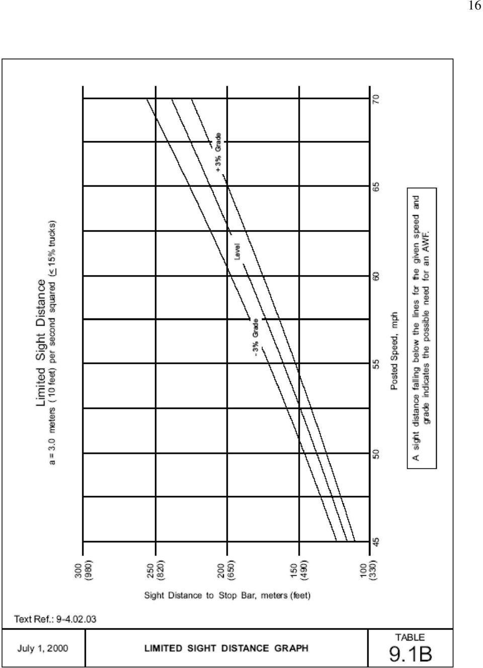
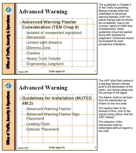
14 14 GUIDELINE 3 Excerpt from the Minnesota Traffic Engineering Manual, July 1, Advance Warning Flashers Consideration An Advance Warning Flasher (AWF) is a device that Mn/DOT uses to convey to the motorist information about the operation of a traffic signal. An AWF is typically found at certain high-speed locations where it may be necessary to get the motorists attention through a visual indication about a pending change in the indication of a traffic signal. The AWF assists the motorists in making safer and more efficient driving decisions by informing them that they must prepare to stop. The AWF configuration, placement, and timing details can be found the Chapter 4M of the MN MUTCD. The following guidelines indicate when the installation of advance warning flashers (AWF) for signal change interval should be considered. Due to the complex nature of traffic flow characteristics, these guidelines should be applied along with engineering judgment. Guidelines should be reviewed for each prospective installation. An AWF should only be installed in response to a specifically correctable problem, not in anticipation of a future problem. Generally, AWF implementation is appropriate only at high-speed locations. Before an AWF is installed, other remedial action should be considered. The following guidelines generally apply only where posted speed is 55 mph or higher: 1. An isolated or an unexpected signalized intersection This situation can occur where there is a long distance from the last intersection at which the mainline is controlled, or the intersection is otherwise unexpected. This guideline may be applicable where the distance from the last intersection is greater than 15 km (10 miles), a freeway terminus, or at other locations where the intersection is unexpected. 2. A Limited sight distance This can occur where the distance to the stop bar, D, with two signal heads visible is insufficient. See Graphs of Limited Sight Distance, Table 9.1A & Table 9-1B. A sight distance falling below the lines for the given speed and grade indicates the possible need for an AWF. 3. Dilemma zone This situation exists when a dilemma zone exists for all traffic or for heavy vehicles. A dilemma zone exists if the yellow interval time cannot practically be set to at least the yellow interval time indicated in Signal Timing Manual. An AWF may be considered but longer yellow should be considered first.

15 15 4. Crashes If an approach has a crash problem, the intersection should be examined for existence of dilemma zone or sight distance restriction. If no sight distance or dilemma zone problems exist, an AWF may not be an appropriate countermeasure for accident problems. 5. Heavy Truck Volume Where the roadway has a grade of 3% or greater and truck volume exceeds 15%. 6. Engineering Judgment Combinations of the above guidelines or other considerations may justify the installation of an AWF. Engineering judgment should be based on additional data such as complaints, violations, conformity of practice, and traffic conflicts. Prior to installing an AWF, consideration should be given to other countermeasures including but not limited to: adjustment of timing parameters which may include increasing yellow and/or all red intervals, improving detection, modification of the signal system as by adding signal heads, adjusting speed limits, and installing continuously operating flashers with standard "signal ahead" warning signs.

16 16
 is a device that, at certain high-speed locations, has been found to provide additional information to the motorist describing the operation")
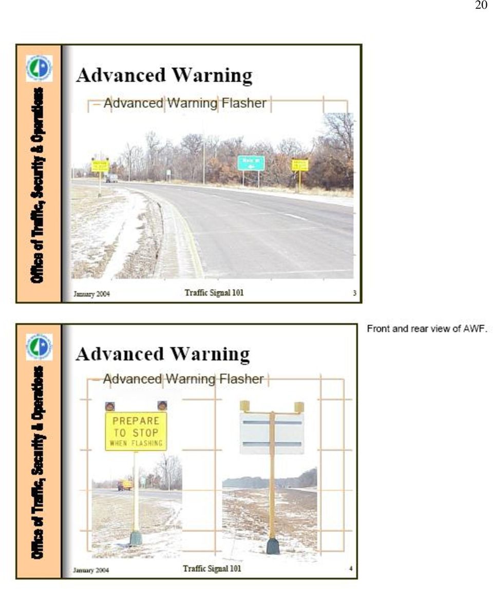
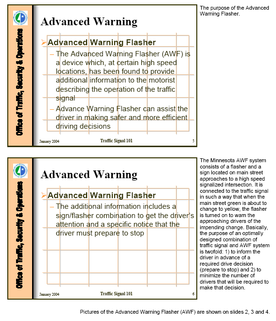
17 17 GUIDELINE 4 Excerpt from the Minnesota MUTCD, December 2001 PART 4. HIGHWAY TRAFFIC SIGNALS Chapter 4M. Advance Warning Flashers 4M.1 Description SUPPORT: The Advanced Warning Flasher (AWF) is a device that, at certain high-speed locations, has been found to provide additional information to the motorist describing the operation of the traffic signal. It has been found that and Advance Warning Flasher can assist the driver in making safer and more efficient driving decisions. The additional information includes a visual indication to get the driver's attention and a specific notice that the driver must prepare to stop. The Minnesota Advance Warning Flasher system consists of a flasher and a sign located on main street approaches to a high-speed signalized intersection. The AWF is connected to the traffic signal in such a way that when the main street green is about to change to yellow, the flasher is turned on to warn the approaching drivers of the impending change. Basically, the purpose of an optimally designed combination of traffic signal and Advance Warning Flasher system is twofold: 1) to inform the driver in advance of a required drive decision (prepare to stop) and 2) to minimize the number of drivers that will be required to make that decision. 4M.2 General Design and Operation GUIDANCE: If used, then the guidelines for installation should be the following: 1. Advance Warning Flasher - The Advanced Warning Flasher assembly is shown in Figure 4M-1. The flasher shall flash yellow in a wig-wag manner prior to the termination of the green (See number 3 below), and during the yellow and red periods of the signal. The flasher will also flash if the signal goes into flashing operation. Power shall be supplied to the Advance Warning Flasher from the signal control cabinet. 2. Advance Warning Flasher Sign Placement The Advance Warning Flasher should be set back from the intersection in accordance with the Table 4M-1. Where this is not possible, the leading flash must be adjusted for the actual distance by using the formula below. At locations on four-lane divided roadway, it shall be placed on both sides of the approach.

18 18 3. Leading Flash - The Leading Flash is the amount of time, prior to the signal turning yellow that the Advance Warning Flasher flashes. It shall flash during the Leading Flash Period and continue flashing through the signal's yellow clearance interval and the red. The Leading Flash time is shown in Table 4M- 1. For existing systems where the placement is other than what is listed in Table 4M-1, the Leading Flash Time can be computed by the following formula: 4. Detector Placement - The detection of the intersection shall be determined without regard to the Advance Warning Flasher.

19 GUIDELINE 5 Training Information from the Minnesota DOT, January

20 20
21 21
22 22
23 23
CHAPTER 11: PEDESTRIAN SIGNS AND SIGNALS
 CHAPTER 11: PEDESTRIAN SIGNS AND SIGNALS Traffic signs and signals should be useful for all pedestrians. It is essential to provide signals that are phased and timed to allow senior citizens, children,
CHAPTER 2 TRAFFIC SIGNS AND HIGHWAY MARKINGS
 CHAPTER 2 TRAFFIC SIGNS AND HIGHWAY MARKINGS This chapter summarizes traffic signs, signals and road markings that control the flow of traffic, making streets and highways safer for motorists, bicyclists
WYDOT Quick Facts TRAFFIC SIGNALS
 TRAFFIC SIGNALS WYDOT Quick Facts 2 Advantages of traffic signals WYDOT Quick Facts Traffic signals control vehicle and pedestrian traffic by assigning priorities to various traffic movements to influence
SIGHT DISTANCE. Presented by Nazir Lalani P.E. Traffex Engineers Inc. N_lalani@hotmail.com WHY IS SIGHT DISTANCE SO IMPORTANT?
 SIGHT DISTANCE Presented by Nazir Lalani P.E. Traffex Engineers Inc. N_lalani@hotmail.com WHY IS SIGHT DISTANCE SO IMPORTANT? Drivers must be able to: Stop for objects in the roadway Stop for stationary
Chapter Forty-seven. RURAL TWO-LANE/MULTILANE STATE HIGHWAYS (New Construction/Reconstruction) BUREAU OF DESIGN AND ENVIRONMENT MANUAL
 BUREAU OF DESIGN AND ENVIRONMENT MANUAL") Chapter Forty-seven RURAL TWO-LANE/MULTILANE STATE HIGHWAYS (New Construction/Reconstruction) BUREAU OF DESIGN AND ENVIRONMENT MANUAL Illinois RURAL TWO-LANE/MULTILANE STATE HIGHWAYS December 2009 2 Illinois
Chapter Forty-seven RURAL TWO-LANE/MULTILANE STATE HIGHWAYS (New Construction/Reconstruction) BUREAU OF DESIGN AND ENVIRONMENT MANUAL Illinois RURAL TWO-LANE/MULTILANE STATE HIGHWAYS December 2009 2 Illinois
This section deals with mandatory and optional equipment for your vehicle as well as suggestions for safer road use.
 3. EQUIPMENT This section deals with mandatory and optional equipment for your vehicle as well as suggestions for safer road use. 3.1 Lights No person shall drive a vehicle on a highway at nighttime or
Guelph Driving School. 246 WOOLWICH ST. Unit C Guelph, Ontario N1H 3V9. Office: 519-829-8801 Cell: 519-362-5664. Email: info@guelphdrivingschool.
 246 WOOLWICH ST. Unit C Guelph, Ontario N1H 3V9 Office: 519-829-8801 Cell: 519-362-5664 Email: info@guelphdrivingschool.com Dear Student, We would like to take this opportunity to thank you for choosing
Analysis of Accidents by Older Drivers in Japan
 Analysis of Accidents by Older Drivers in Japan Kazumoto Morita 1, Michiaki Sekine 1 1 National Traffic Safety and Environment Laboratory, Japan Abstract Since Japan is a rapidly aging society, ensuring
BEST PRACTICE FOR TRAFFIC ENGINEERING DEVICES & OPERATIONS IN SCHOOL AREAS
 C I T Y O F C O L O R A D O S P R I N G S E N G I N E E R I N G D I V I S I O N T R A F F I C E N G I N E E R I N G T E A M SCHOOL SAFETY PROGRAM POLICY MANUAL BEST PRACTICE FOR TRAFFIC ENGINEERING DEVICES
CHAPTER 2B. REGULATORY SIGNS
 December 2000 Page 2B-1 CHAPTER 2B. REGULATORY SIGNS Section 2B.01 Application of Regulatory Signs Regulatory signs shall be used to inform road users of selected traffic laws or regulations and indicate
Stop Alert Flasher with G-Force sensor
 Stop Alert Flasher with G-Force sensor Stop Alert module creates brake light flashing effect to catch attention of the drivers behind to avoid dangerous rear end collision. The flasher module is a state
FHWA Minnesota Division Guidance for the Preparation of a FHWA INTERSTATE ACCESS REQUEST
 FHWA Minnesota Division Guidance for the Preparation of a FHWA INTERSTATE ACCESS REQUEST August 2003 Background: The Federal Highway Administration (FHWA) has retained all approval rights to the control
Seagull Intersection Layout. Island Point Road - A Case Study. Authors: John Harper, Wal Smart, Michael de Roos
 Seagull Intersection Layout. Island Point Road - A Case Study Authors: John Harper, Wal Smart, Michael de Roos Presented by Mr John Harper, Road Safety and Traffic Services Manager Phone: 4221 2456 Mobile:
Stop The stop sign, a red octagon with white lettering, means come to a full stop and be sure the way is clear before proceeding.
 Tr a f f i c S i g n s 7 7. TRAFFIC SIGNS Many collisions and near crashes occur as a result of drivers who ignore or fail to respond appropriately to traffic signs. It is essential that the meaning of
How To Improve Safety
 Collision Diagrams Collision diagrams are used to display and identify similar accident patterns. They provide information on the type and number of accidents; including conditions such as time of day,
Guidelines. Work Zone Access and Egress
 Guidelines on Work Zone Access and Egress This document describes concerns associated with work zone access and egress. The document offers recommended practices and describes effective strategies and
METHODS FOR ESTABLISHING SAFE SPEEDS ON CURVES
 Page 1 of 4 PRACTICES PART SECTION SUB-SECTION TRAFFIC OPERATIONS General Collision exposure is usually greater along horizontal curves than along tangent sections of a highway. The potential for collisions
STREET LIGHTING CONSTRUCTION DESIGN CRITERIA
 STREET LIGHTING CONSTRUCTION DESIGN CRITERIA DC9-001 GENERAL. Proposed street lighting construction in the city of Olathe shall in all respects conform to the technical criteria for analysis and design
PRIVATELY OPERATED TOURIST INFORMATION CENTER SIGNS GENERAL INFORMATION & APPLICATION
 PRIVATELY OPERATED TOURIST INFORMATION CENTER SIGNS GENERAL INFORMATION & APPLICATION Dear Applicant: Enclosed is a copy of MassDOT - Highway Division's Privately Operated Tourist Information Center Signs
100 Design Controls and Exceptions
 Table of Contents 100 Introduction... 1 101 Functional Classification... 1 101.1 General... 1 101.2 Urban & Rural... 1 101.3 Classification Used In ODOT Design Criteria... 1 102 Traffic Data... 2 102.1
STANDARD SPECIFICATIONS FOR SIGNAGE, STRIPING, AND LIGHTING TOWNSHIP OF STANFORD
 STANDARD SPECIFICATIONS FOR SIGNAGE, STRIPING, AND LIGHTING TOWNSHIP OF STANFORD TABLE OF CONTENTS 1.00 2.00 3.00 4.00 GENERAL REQUIREMENTS MATERIALS DESIGN LAYOUT STANDARD PLATES Page No. 1 1 3 5 STANDARD
Chapter 11 SAFE CURVE SPEED STUDY
 Topic No. 750-020-007 January 2000 Chapter 11 SAFE CURVE SPEED STUDY 11.1 PURPOSE The purpose of the Safe Curve Speed Study (Form No. 750-020-12) is to determine the safe speed that a vehicle can negotiate
TRACKING DRIVER EYE MOVEMENTS AT PERMISSIVE LEFT-TURNS
 TRACKING DRIVER EYE MOVEMENTS AT PERMISSIVE LEFT-TURNS Michael A. Knodler Jr. Department of Civil & Environmental Engineering University of Massachusetts Amherst Amherst, Massachusetts, USA E-mail: mknodler@ecs.umass.edu
TH 23 Access Management Study Richmond to Paynesville
 TH 23 Access Management Study Richmond to Paynesville Prepared For: Minnesota Department of Transportation District 8 Prepared By: Short Elliott Hendrickson Inc. July 2015 Table of Contents I. Introduction...
GUIDELINES FOR MOVEMENT OVER SOUTH CAROLINA HIGHWAYS OF OVERSIZE AND OVERWEIGHT VEHICLES AND LOADS
 GUIDELINES FOR MOVEMENT OVER SOUTH CAROLINA HIGHWAYS OF OVERSIZE AND OVERWEIGHT VEHICLES AND LOADS Statutory Authority: Section 56-5-4010 through 56-5-4230 and 57-3-130 through 57-3-160 A. Implements of
Accident Analysis of Sheridan Road between Isabella Street and South Boulevard
 Accident Analysis of Sheridan Road between Isabella Street and South Boulevard Prepared for TranSystems Corporation for the City of Evanston Submitted by Regina Webster & Associates, Inc. Date: 08/15/2008
Adaptive Cruise Control System Overview
 5th Meeting of the U.S. Software System Safety Working Group April 12th-14th 2005 @ Anaheim, California USA 1 Introduction Adaptive Cruise System Overview Adaptive Cruise () is an automotive feature that
Texas DOT Vehicle Fleet Warning Light Policy Research
 T Texas DOT Vehicle Fleet Warning Light Policy Research Gerald L. Ullman Texas Transportation Institute Texas A & M University Don Lewis Texas Department of Transportation his paper presents an overview
Road Signs Recognition Quiz
 Road Signs Recognition Quiz Place your answer for each of the signs/pavement markings on the answer sheet. Ready to Roll? Here Comes Sign # 1... #1 A No right turn B Right turn only C Warning, no turn
Design and Implementation of Slot Left-Turn Lanes on the Manitoba Highway Network
 Design and Implementation of Slot Left-Turn Lanes on the Manitoba Highway Network Brent Hartmann, P. Eng., Project Design Engineer, Manitoba Infrastructure and Transportation Derek Durant, P. Eng., Senior
Document Name: Driving Skills. Purpose: To outline necessary driving skills required to maximize driving safety.
 Document Name: Driving Skills Date Created: 8 October 2013 Date Reviewed: 4 February 2014 Date Approved: 29 July 2015 Purpose: To outline necessary driving skills required to maximize driving safety. Overview:
Delineation. Section 4 Longitudinal markings
 Delineation Section 4 Longitudinal markings The delineation guidelines have been developed to assist in designing and maintaining a quality delineation system. The guidelines are to comprise 19 sections
Freeway Driving Demands Special Skills
 Demands Special Skills Demands Special Skills Traveling today s highways can be a frustrating, confusing journey through a maze of roadblocks, detours and traffic jams. With more than 161,000 miles of
Driving in Fog, Rain and Wind for School Bus Drivers. Reference Guide and Test
 Driving in Fog, Rain and Wind for School Bus Drivers Reference Guide and Test Introduction Every school year bus drivers are faced with adverse driving conditions. Pounding rain storms, wet slippery roads,
Static Warning Signs for Occasional Hazards: A Synthesis of Research and Practice
 Static Warning Signs for Occasional Hazards: A Synthesis of Research and Practice Final Report Ahmed Al-Kaisy Western Transportation Institute Montana State University Bozeman, Montana Research Project
EFFECTIVENESS OF RED LIGHT CAMERAS
 In This White Paper EFFECTIVENESS OF RED LIGHT CAMERAS A Texas Transportation Institute White Paper By Brian Bochner and Troy Walden April 2010; corrected July 6, 2010 Background... 1 Purpose of Enforcement
Manitoba Infrastructure and Transportation. Guide for Establishing Reduced-Speed School Zones
 Overview Guide for Establishing Reduced-Speed School Zones The Highway Traffic Act authorizes local governments, such as municipalities, Northern Community Councils and First Nation Band Councils, to make
GUIDELINES. for oversize and overmass vehicles and loads MAY 2006. Government of South Australia. Department for Transport, Energy and Infrastructure
 ESCORTING GUIDELINES ESCORTING GUIDELINES SCORTING GUIDELINES ESCORTING GUIDELINES ESCORTING ESCORTING GUIDELINES for oversize and overmass vehicles and loads Government of South Australia Department for
Safety Engineering Policy Memorandum
 Safety Engineering Policy Memorandum SAFETY 2-13 Automated Traffic Law Enforcement Systems: Red Light Running (RLR) Camera Enforcement Systems and Automated Railroad Grade Crossing (RGC) Enforcement Systems
Table of Contents. Traffic Control Devices (Signs, Channelizing Devices, Lighting Devices, Pavement Markings) 2-7
 2-7") 1 Table of Contents Introduction 2 Traffic Control Devices (Signs, Channelizing Devices, Lighting Devices, Pavement Markings) 2-7 Five Parts of a Traffic Control Zone 8 Buffer Space Guidance 9 Taper Length
1 Table of Contents Introduction 2 Traffic Control Devices (Signs, Channelizing Devices, Lighting Devices, Pavement Markings) 2-7 Five Parts of a Traffic Control Zone 8 Buffer Space Guidance 9 Taper Length
Disputed Red Light Accidents: A Primer on Signal Control. Jon B. Landerville, MSME, PE Edward C. Fatzinger, MSME, PE Philip S.
 Disputed Red Light Accidents: A Primer on Signal Control Jon B. Landerville, MSME, PE Edward C. Fatzinger, MSME, PE Philip S. Wang, MSME Intersection Accident Statistics Intersection accidents occur on
REVIEW OF GUIDELINES FOR ESTABLISHING SCHOOL SPEED ZONES
 Fitzpatrick 1 3 rd Urban Street Symposium June 24-27, 2007 Seattle, Washington REVIEW OF GUIDELINES FOR ESTABLISHING SCHOOL SPEED ZONES By Kay Fitzpatrick, Ph.D., P.E. Research Engineer Texas Transportation
Publication 213 - Shadow Vehicle Utilization during Mowing Operations
 494-15-06 DATE: December 16, 2015 SUBJECT: Publication 213 - Shadow Vehicle Utilization during Mowing Operations TO: District Executives FROM: Richard N. Roman, P.E., Director Richard Roman /s/ Bureau
1. It would create hazardous effects of storm water run-off. 3. It would increase hazardous driving conditions on the public road.
 SECTION 6: REQUIREMENTS FOR A DRIVEWAY CONNECTION A. Required information. The application shall be accompanied by a sketch of the proposed driveway which at a minimum shall indicate: 1. Geometric information
Bicycles and Proper Highway Restrictions
 Arizona Revised Statutes azbikelaw.org Title 28 - Transportation Laws: Excerpts related to Bicycling w/annotations Law last changed April 17, 2000. My notations updated: (Mar 2014 -- added 28-905 "dooring"
TEMPORARY TRAFFIC MANAGEMENT Operate as a Traffic Controller (TC) for low volume and Level 1 roads
 for low volume and Level 1 roads") 1 of 8 level: 3 credit: 4 planned review date: October 2008 sub-field: purpose: Highway Construction and Maintenance This unit standard is for people who may be appointed, subject to guidance and monitoring
1 of 8 level: 3 credit: 4 planned review date: October 2008 sub-field: purpose: Highway Construction and Maintenance This unit standard is for people who may be appointed, subject to guidance and monitoring
Operating Vehicle Control Devices
 Module 2 Topic 3 Operating Vehicle Control Devices 1. Identify the vehicle controls in the pictures below: 1. 2. 3. 4. 7. 7. 5. 6. 1. accelerator 2. parking brake 3. foot brake 4. gear shift lever_ 5.
Traffic controllers and speed zones
 Section 8 Traffic controllers and speed zones 8.1 Traffic Controllers 8.1.1 General (AS 4.10.2) (a) Equipment Traffic controllers shall wear approved high visibility clothing and shall control traffic
Professional Truck Driver Training Course Syllabus
 Professional Truck Driver Training Course Syllabus The curriculum standards of this course incorporate the curricular recommendations of the U. S. Department of Transportation s Federal Highway Administration
Prepared by North Dakota Local Technical Assistance Program Upper Great Plains Transportation Institute North Dakota State University
 Prepared by North Dakota Local Technical Assistance Program Upper Great Plains Transportation Institute North Dakota State University http://www.ndltap.org in cooperation with North Dakota Department of
BEFORE-AND-AFTER STUDY OF THE EFFECTIVENESS OF RECTANGULAR RAPID-FLASHING BEACONS USED WITH SCHOOL SIGN IN GARLAND, TEXAS
 BEFORE-AND-AFTER STUDY OF THE EFFECTIVENESS OF RECTANGULAR RAPID-FLASHING BEACONS USED WITH SCHOOL SIGN IN GARLAND, TEXAS Marcus A. Brewer (corresponding author) Associate Research Engineer Texas Transportation
TRAFFIC ENGINEERING DIVISION MEMORANDUM
 VIRGINIA DEPARTMENT OF TRANSPORTATION TRAFFIC ENGINEERING DIVISION MEMORANDUM NUMBER: TE-363 SUPERSEDED: N/A DATE: July 28, 2009 SUNSET DATE: (see footnote) GENERAL SUBJECT: Engineering and Administration
Access Spacing and Accidents
 Access Spacing and Accidents A Conceptual Analysis HERBERT S. LEVINSON Transportation Consultant 40 Hemlock Road New Haven, CT 06515 ABSTRACT This paper develops a method for predicting the safety of arterial
Incident Management Response Plan Hampton Roads Highway Incident Management Committee
 Incident Management Response Plan Hampton Roads Highway Incident Management Committee Multi-Jurisdictional Memorandum of Understanding Highway Incident Management Plan This memorandum of understanding
 Walkable Communities Florida Department of Transportation State Safety Office Pedestrian and Bicycle Program April 1995 www.dot.state.fl.us/safety Twelve Steps for an Effective Program Page 1 Twelve Steps
City of Auburn Americans with Disabilities Act (ADA) Transition Plan for Curb Ramps, Sidewalks, and Pedestrian Signals ADA TRANSITION PLAN
 Transition Plan for Curb Ramps, Sidewalks, and Pedestrian Signals ADA TRANSITION PLAN") Americans with Disabilities Act (ADA) Transition Plan for Curb Ramps, Sidewalks, and Pedestrian Signals ADA TRANSITION PLAN December 21, 2009 Public Works Department 171 N. Ross Street, Suite 200 Auburn,
Americans with Disabilities Act (ADA) Transition Plan for Curb Ramps, Sidewalks, and Pedestrian Signals ADA TRANSITION PLAN December 21, 2009 Public Works Department 171 N. Ross Street, Suite 200 Auburn,
Superseded. The average time for a normal repair after a crash is approximately 1.5 to 2 hours for a 3- person crew.
 To: Subject: Purpose: All HQ Directors: Operations, Planning and Major Projects All Regional Directors All Regional Managers, Engineering All Regional Traffic Engineers All District Managers Transportation
RULES OF THE ROAD BY LWTL Staff Writer
 RULES OF THE ROAD BY LWTL Staff Writer Publisher s Note This is the First of a Three Part Series on Pedestrian and Bicycle Safety. This First Part is made available to all readers. The final two parts
Lineside Signal Spacing and Speed Signage
 Document comes into force on 05/12/15 Supersedes GKRT0075 Iss 3 on 05/12/15 Date September 15 Lineside Signal Spacing and Speed Synopsis This document specifies the minimum distances that must be provided
TEST ON Driving Safely Among Bicyclists and Pedestrians
 TEST ON Driving Safely Among Bicyclists and Pedestrians Next you will take a 16 question test about driving safely among bicyclists and pedestrians. Please take out a sheet of paper to mark down and score
ACCELERATION OF HEAVY TRUCKS Woodrow M. Poplin, P.E.
 ACCELERATION OF HEAVY TRUCKS Woodrow M. Poplin, P.E. Woodrow M. Poplin, P.E. is a consulting engineer specializing in the evaluation of vehicle and transportation accidents. Over the past 23 years he has
INSTRUCTOR S GUIDE. Stay on the Right Track Highway-Railway Crossing Awareness Training for Newly Licensed Drivers
 INSTRUCTOR S GUIDE Stay on the Right Track Highway-Railway Crossing Awareness Training for Newly Licensed Drivers WHAT WE DO Operation Lifesaver is a nationwide, non-profit public information and education
Atlanta, Georgia Road Test
 1. When driving your car Into traffic from a parked position, you should: A. Sound your horn and pull Into the other lane. B. Signal and proceed when safe. C. Signal other traffic and pull directly into
Lane Shutdowns and Mobile Operations
 PERFORMANCE ACTIVITY 408 TREE REMOVAL WORK DESCRIPTION 1 WORK DESCRIPTION 2 Fallen Tree Standing Tree 408 TREE REMOVAL ACTIVITY DESCRIPTION Cut and remove tree as necessary. WORK DESCRIPTION 1 Fallen Tree
IV. INDUSTRIAL TRACK DESIGN
 IV. INDUSTRIAL TRACK DESIGN 4.01 GENERAL The following sections govern the criteria to be used in the designing of industry tracks served, or to be served, by the Railway Company. Any deviation from these
SECTION 611 ACCEPTANCE PROCEDURES FOR TRAFFIC CONTROL SIGNALS AND DEVICES
 SECTION 611 ACCEPTANCE PROCEDURES FOR TRAFFIC CONTROL SIGNALS AND DEVICES 611-1 Description. This Section sets forth Contract acceptance procedures for installations of traffic control signals and devices
Physics: Principles and Applications, 6e Giancoli Chapter 2 Describing Motion: Kinematics in One Dimension
 Physics: Principles and Applications, 6e Giancoli Chapter 2 Describing Motion: Kinematics in One Dimension Conceptual Questions 1) Suppose that an object travels from one point in space to another. Make
Appendix A In-Car Lessons
 Driver Education Classroom and In-Car Curriculum Appendix A In-Car Lessons Table of Contents In-Car Lessons Introduction..... A-4 Overview and Objectives Teacher Information and Resources Lesson #1 Developing
ENGINEERING SOLUTIONS FOR DESIGNING YOUR SAFE ROUTES
 How to Get Started ENGINEERING SOLUTIONS FOR DESIGNING YOUR SAFE ROUTES Design Elements Selecting appropriate design treatments for school neighborhoods creates environments that address the needs of all
The partnership has selected three intersections where enforcement, education, and engineering initiatives are being implemented to improve safety:
 Hamilton-Finn Suite 310 Tel. (403) 207-6000 Road Safety 3016 5th Avenue N.E. Fax. (403) 273-3440 Consultants Ltd. Calgary, Alberta dawatt.dawatt.com www.hamiltonfinn.ca January 19, 2005 Mr. Don Szarko,
ACCELERATION CHARACTERISTICS OF VEHICLES IN RURAL PENNSYLVANIA
 www.arpapress.com/volumes/vol12issue3/ijrras_12_3_14.pdf ACCELERATION CHARACTERISTICS OF VEHICLES IN RURAL PENNSYLVANIA Robert M. Brooks Associate Professor, Department of Civil and Environmental Engineering,
0.0 Curb Radii Guidelines Version 1.0.2
 Background In early 2014, Transportation Services initiated a review of the Division's design guidelines and standards to move our organization in a direction consistent with the transportation departments
Lineside Signal Spacing and Speed Signage
 Document to be withdrawn as of 03/12/11 To be superseded by GKRT0075 Iss 2 published on 03/09/11 Date March 11 Lineside Signal Spacing and Speed Synopsis This document specifies the minimum distances that
Position Paper: Effectiveness of Speed Cameras and Use in Western Australia, Victoria and New South Wales
 Position Paper: Effectiveness of Speed Cameras and Use in Western Australia, Victoria and New South Wales The Government has committed to the implementation of Toward Zero, including the recommended implementation
Safety Evidence for Bicycling
 Photo: Boegh (Flickr) Cycling in Cities Research Program School of Population & Public Health The University of British Columbia Faculty of Health Sciences Simon Fraser University Driving near bicyclists
1. REPORT CONTEXT Description of the development (include all of the following that are known at the time of the application):
:") Transportation Assessment and Management Study Guidelines for Consultants INTRODUCTION This document is intended to provide guidelines for transportation consultants who produce Transportation reports
Transportation Assessment and Management Study Guidelines for Consultants INTRODUCTION This document is intended to provide guidelines for transportation consultants who produce Transportation reports
In addition to looking for applications that can be profitably examined algebraically,
 The mathematics of stopping your car Eric Wood National Institute of Education, Singapore In addition to looking for applications that can be profitably examined algebraically, numerically
ROAD SIGNS IN JAPAN PARKING SIGNS. No Parking or Stopping Anytime SIZE & WEIGHT LIMIT SIGNS SPEED LIMIT SIGNS
 ROAD SIGNS IN JAPAN Stop Slow & all Do Not Enter & Motorcycles Road Large Sized Trucks & Special Duty Road All Except Two Wheeled Light Except Bicycles Large Passenger No Right Turn No Passing No U-Turn
Best Practice For Selecting Bus Stop Locations
 Best Practice For Selecting Bus Stop Locations There is no perfect school bus stop, because it is impossible to eliminate all potential hazards, but guidelines and training are still necessary to ensure
The Need for Traffic Incident Management
 The Need for Traffic Incident Management With traffic incidents responsible for approximately 50-60% of the congestion delays motorists encounter on the nation s roadways every day, increased roadway capacity
Texas Virtual Driver Education Course Syllabus
 Texas Virtual Driver Education Course Syllabus By Amarillo Independent School District INTRODUCTION: 46:04 Welcome/Tutorial 5 minutes Virtual Drive Notice 1 minute Audio/Computer Requirements 3 minutes
Florida Class E Knowledge Exam Road Rules Practice Questions www.gdlinstitute.org
 If you purchase the Value Package from GDL Institute, over 100 additional practice questions are included at no additional cost. Use discount code PQ10 and receive 10% off of the package price! 1. If you
CHAPTER 10 SCHOOL AREA PEDESTRIAN SAFETY
 STATE OF CALIFORNIA BUSINESS, TRANSPORTATION AND HOUSING DEPARTMENT OF TRANSPORTATION TRAFFIC MANUAL CHAPTER 10 AREA PEDESTRIAN SAFETY 10-00 - Introduction, General Provisions, Table of Contents and List
Signs, Pavement Markings, and Work Zones. Signs, Pavement Markings, and Work Zones
 Signs, Pavement 3 Signs, Pavement 77 3 Signs, Pavement This chapter includes information on highway signs that are intended to guide and inform you while you are driving. It includes information on the
California Manual on Uniform Traffic Control Devices. FHWA s MUTCD 2009 Edition as amended for use in California
 California Manual on Uniform Traffic Control Devices FHWA s MUTCD 2009 Edition as amended for use in California Federal Highway Administration California Division 650 Capitol Mall, Suite 4-100 Sacramento
Kane County Division of Transportation Policy for Red Light Running (RLR) Photo Enforcement Systems
 Photo Enforcement Systems") Kane County Division of Transportation Policy for Red Light Running (RLR) Photo Enforcement Systems Effective: APRIL 1, 2008 Revised October 12, 2010 Executive Summary Red Light Running (RLR) is one of
Kane County Division of Transportation Policy for Red Light Running (RLR) Photo Enforcement Systems Effective: APRIL 1, 2008 Revised October 12, 2010 Executive Summary Red Light Running (RLR) is one of
Ministero delle Infrastrutture e dei Trasporti
 Italian National Investigating Body Massimo Costa Geneva 12-13 May 2014 Reducing the risk at level crossings, optimizing the time of notice of the closure of the barriers Specifically: optimization of
Chapter 4 DEFENSIVE DRIVING
 Chapter 4 DEFENSIVE DRIVING Chapter 4 Table of Contents Chapter 4 DEFENSIVE DRIVING... 4-1 DEFENSIVE DRIVING... 4-3 Positioning The Bus... 4-3 When Making a Turn at an Intersection... 4-3 Making the perfect
Adaptive Cruise Control
 33 Adaptive Cruise Control Adaptive Cruise Control Adaptive Cruise Control is a driving support system intended to allow more comfortable driving on expressways, freeways and interstate highways. The vehicle
Emergency Traffic Management
 Emergency Traffic Management Richard Elvey Captain Calgary Fire Department The City of Calgary Dr. John Morrall, P. Eng. Professor Emeritus of Civil Engineering University of Calgary Paper prepared for
SIGNING SEQUENCE IN ADVANCE OF VEHICLE INSPECTION. STATIONS (VIS & MIS) Page 1of 3
 Page 1of 3") Issued: JUL 2007 STATIONS (VIS & MIS) Page 1of 3 RECOMMENDED PRACTICES PART SECTION SUB-SECTION HIGHWAY SIGNS TYPICAL SIGNING PLANS General The safety of motorists using Alberta highways, and the maintenance
Issued: JUL 2007 STATIONS (VIS & MIS) Page 1of 3 RECOMMENDED PRACTICES PART SECTION SUB-SECTION HIGHWAY SIGNS TYPICAL SIGNING PLANS General The safety of motorists using Alberta highways, and the maintenance
DRIVING TEST POSSIBLE QUESTIONS & ANSWERS.
 DRIVING TEST POSSIBLE QUESTIONS & ANSWERS. Question 1. What shape and colour is a warning sign? Diamond Shape - Yellow and Black Question 2. When should you not drive? While under the influence of alcohol,
Speed Limit Policy Isle of Wight Council
 APPENDIX C - 59 Speed Limit Policy Isle of Wight Council June 2009 Contents Section 1 Introduction 1.1 Links with the Local Transport Plan Section 2 Speed Limits on Urban Roads and Residential Areas 2.1
WORK ZONE SAFETY TOOLBOX
 Maryland State Highway Administration Page 1 of 7 CB WIZARD ALERT SYSTEM A. DESCRIPTION The CB Wizard alert system is an unmanned CB radio transmitter designed to automatically broadcast work zone safety
Highway-Rail Grade Crossing Training for School Bus Drivers
 D E C I D E S M A R T, A R R I V E S A F E Highway-Rail Grade Crossing Training for School Bus Drivers Presented by Operation Lifesaver, Inc. in cooperation with the National Association of State Directors
Traffic Guidelines Manual
 State of Wisconsin Department of Transportation ORIGINATOR State Traffic Engineer Traffic Guidelines Manual 2-3-35 CHAPTER 2 Signing SECTION 3 Warning Signs SUBJECT 35 Advisory Speed on Curves A. PURPOSE
SunGuide Software. Color Dynamic Message Sign Support Concept of Operations. Technical Memorandum. Version 1.0. February 24, 2012.
 Technical Memorandum SunGuide Software Color Dynamic Message Sign Support Concept of Operations Version 1.0 February 24, 2012 Prepared for: Florida Department of Transportation Intelligent Transportation
Chapter 6. Intersections. 6 Intersections
 Chapter 6 Intersections 6 Intersections Chapter 6 Intersection Design 6.1 Introduction An intersection is the area where two or more streets join or cross at-grade. The intersection includes the areas
Analysis of Accident Statistics
 Analysis of Accident Statistics I. BACKGROUND To ensure that safety objectives are met, a distinction must be made between: (1) locations which are hazardous as identified based on accident experiences,
LOCATION AND DESIGN DIVISION
 VIRGINIA DEPARTMENT OF TRANSPORTATION LOCATION AND DESIGN DIVISION INSTRUCTIONAL AND INFORMATIONAL MEMORANDUM GENERAL SUBJECT: DESIGN EXCEPTIONS / WAIVERS SPECIFIC SUBJECT: DESIGN EXCEPTION REQUEST FORM