EMC Standards: Standards of good EMC engineering
|
|
|
- Charles Porter
- 7 years ago
- Views:
Transcription
1 Electromagnetic Compatibility (EMC) IEEE Definition Origin, control, and measurement of electromagnetic effects on electronic and biologic systems. IEEE EMC Society Areas of Interest EMC Standards: Standards of good EMC engineering practice. Measurement Technology: Instrumentation and methods of measurement. RF Noise Sources: Studies of the origins and characteristics of electromagnetic emissions, both natural and man-made (but not designed to convey intelligence). Equipment EMC: Emissions and susceptibility of electronic equipment and components. Systems EMC: Emissions and susceptibility of electronic systems and subsystems. Spectrum Utilization: Utilization of the electromagnetic spectrum by, and frequency allocation of, signals designed to convey intelligence. TEMPEST and EMP: Electromagnetic considera-

2 tions of (i) secure communications and (ii) nuclear pulses. Radiation Hazards: Undesirable electromagnetic interactions with biological systems, fuel, and ordnance. Walsh Functions: Applications of orthogonal non-sinusoidal functions. Course Objective To cover the practical aspects of noise and interference suppression and control in electronic circuits for the engineer who is or will be involved in hardware design. Course Level Design oriented with a minimum mathematical complexity. Simplified models representing physical phenomena having physical meaning. TheInterferenceProblem The operation of diverse circuits in close proximity gives rise to what is called EMI, which stands for Electromagnetic Interference (formerly called RFI which stood for radio

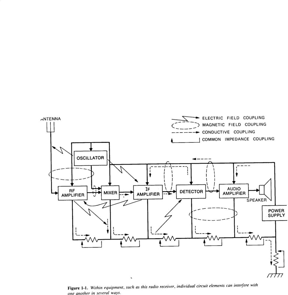
3 Radio Frequency Interference). Examples Circuits for communications. Circuits for power distribution. Circuits for automation and control. Computers. Effect of Circuit Size As circuits become smaller, EMI problems become worse in general. Integrated circuits are particularly susceptible to EMI, especially LSI circuits. Major Equipment Design Objective Elimination (or avoidance) of EMI. This means that equipment should be designed so that it is not affected by noise nor is itself a source of noise. Example of interference inside equipment: Figure 1-1 shows how EMI can occur inside a radio receiver. There are four coupling mechanisms illustrated in the figure:

4 Electric field coupling caused by voltage difference between conductors. Magnetic field coupling caused by current flow in conductors. Conductive coupling noise coupled between components through interconnecting wires, e.g. through power supply and ground wires. Common impedance coupling caused two or more currents flowing in the same impedance, e.g. in power supply and ground wires. If the radio is free of these EMI sources, it will operate in the lab. Example of interference when equipment is installed in the real world : Figure 1-2 shows how external noise sources can interfere with the radio receiver when it is taken out of the lab. Some sources of noise: Electric field coupling from: High-voltage power lines. Broadcast antennas. Communications transmitters. Vehicle ignition systems.

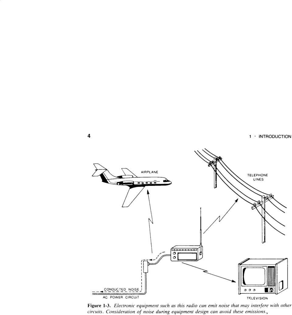
5 Electric machinery. Conductive coupling through ac power lines. Example of how equipment in the real world interferes with other equipment: Figure 1-3 shows how a radio can interfere with other equipment. Some examples are: Electric field coupling to: Broadcast receivers. Telephone lines. Communications receivers. Conductive coupling through ac power lines. Designing for EMC Equipment should be designed to: Function properly in its intended electromagnetic environment, i.e. to be immune to EMI. Not be a source of pollution to that environment, i.e. nottobeanemitterofemi. Susceptibility tends to be self-regulating. For example, consumers will avoid purchasing it. Emission tends to not be self-regulating if the product is not affected by its own emissions. As a result, regulatory bodies impose standards to

6 control emissions. Two Approaches for EMC Design Crisis Approach: Disregard EMC until the design is completed. Use add-ons to fix the problems as they arise during testing and field experience. Also called the Band-Aid approach. Tends to be expensive. Systems Approach: Consider EMC throughout the design. Anticipate all possible problems from the start. Thorough EMC test of final prototypes. More cost effective because EMC is designed into the product and not added on when problems later arise. Example: Figure 1-4 illustrates how available techniques for EMC and cost vary with time during equipment development. EMC Regulations Those that affect the U.S. are primarily written by three agencies: The FCC or Federal Communications Commission. The U.S. Department of Defense (MIL-STD). The CISPR or International Special Committee on Radio Interference.

7 FCC Regulates the use of all licensed radio and wire communications. Three sections of FCC Rules are applicable to non-licensed electronic equipment. Part 15. Part 18. Part 68. FCC Rules Part 15 States standards and requirements for RF devices, i.e. any device capable of emitting RF energy by radiation, conduction, or other means. Rf energy defined as any electromagnetic energy inthe10khzto3ghzrange. Controls operation of low-power RF transmitters that do not require a license, e.g. garage door openers. Controls interference to RF communications services caused by other equipment that emits RF energy or noise, including digital electronics. FCC Rules Part 18 Specifies standards and operational conditions for industrial, scientific, and medical (ISM) equipment

8 that uses RF for any purpose not intended for radio communications. ISM equipment includes medical diathermy equipment, industrial heating equipment, RF welders, RF lighting devices, and other non-communications devices. FCC Rules Part 68 Sets standards for equipment that connects to the telephone network Intended for the protection of the network from harm caused by equipment and its wiring. Harm to telephone network includes: Electrical hazards to telephone company workers. Damage to telephone company equipment. Malfunction of telephone company billing equipment. Degradation of telephone company services. Ensures compatibility of hearing aids and telephones. FCC Part 15, Subpart J Written to control EMI generated by digital electronics.

9 Places limits on radiated emission in the 30 MHz to 1 GHz band. Places limits on conducted emission on ac power lines in the 450 khz to 30 MHz band. Regulations were result of increasing complaints of interference to radio and tv reception caused by digital electronics. Interference from Computers Reported to interfere with almost all radio services, particularly those below 200 MHz, including: Police radio. Aeronautical radio. Broadcast services. Contributing factors: Prolification of digital equipment, particularly in the home. Increasing computer speeds, causing EMI problems that didn t occur with slower computers. Production economics which replace shielded steel cabinets with cheaper plastic cabinets.

10 FCC Definition of a Computing Device Any electronic device that generates and uses timing pulses in excess of 10,000 pulses per second and uses digital techniques. Why 10 khz? Because harmonics extend to much higher frequencies. Two classes of devices. Class A Intended for commercial, industrial, or business use. Class B Intended for home use. More likely to be used close to radio and tv receivers. Limits are about 10 db more restrictive than Class A devices. Devices cannot be legally advertised without the statement that thedeviceissubjecttofccrules and will comply with the rules prior to delivery. Personal computers and peripherals must be FCC certified before they can be marketed. Radiated Emission Certification Tests Must be made on a complete system with all cables connected. Figure 1-5 shows the test fixture for radiated emission tests.

11 Tables 1-1 and 1-2, respectively, specify maximum class A and B emission limits. Figure 1-6 compares the Class A and B limits, where the Class A limits are extrapolated to a 3-m distance. Class B limits are lower by about a factor of 3 (about 10 db). Conducted Emission Certification Tests Emissions conducted onto ac power lines and radiated from the lines are the primary cause of interference below 30 MHz Figure 1-7 shows the test fixture for conducted emissions Measurements must be made with a line impedance stabilization network (LISN) to isolate the EMI receiver from the ac line Table 1-3 specifies Class A and B conducted emission limits International Harmonization CISPRformedin1934todeterminelimitsonEMI Europe adopted the CISPR limits U.S. is a voting member of the CISPR and FCC has been pressured to adopt its limits
 to isolate the EMI receiver from the ac line Table 1-3 specifies Class A and B conducted emission")
12 Figures 1-8 and 1-9 compare the FCC and CISPR limits for radiated and conducted emissions. Military Standards More stringent than FCC limits Cover30Hzto40GHzrange Measurement techniques require shielded room, whereas FCC requires an open field Figure 1-10 summarizes the MIL-STD requirements Typical Noise Path Figure 1-11 shows three necessary elements for a noise path Noise source Coupling channel Receptor Three ways to break a noise path Suppress the source Desensitize the receiver Eliminate transmission through the coupling channel

13 ExampleofaNoisePath Figure 1-12 illustrates a low-level circuit near a dc motor housed in a shield Sparks between the motor brushes and armature cause noise on the motor control lines Noise radiates to the low-level circuit Breaking the coupling channel is only option Suppress noise conduction out of the shield Suppress noise radiation from the leads Use of Network Theory Solving Maxwell s equations for an exact analysis is difficult Electric circuit analysis is used to obtain approximate solutions Assumptions in analyzing a circuit All electric fields are confined to the interior of capacitors All magnetic fields are confined to the interior of inductors Circuit dimensions are small compared to a wavelength. (At 300 MHz λ ' 1 m.) Noise coupling channels are modeled as equivalent

14 lumped component networks Electric Field Coupling Figure 1-13 illustrates E-field coupling between a source and a grounded circuit Coupling channel modeled by a capacitor Magnetic Field Coupling Figure 1-14 illustrates B-field coupling between a current carrying conductor and another conductor Coupling channel modeled by a transformer Methods of Noise Coupling Conductive coupling noise coupled on a conductor, e.g. power supply leads, ac power lines, etc. Common impedance coupling when currents from two or more circuits flow through the same impedance. Figures 1-15 and 1-16 illustrate common impedance coupling Electric and magnetic field coupling In the near field, E and H field coupling are treated separately In the far field, coupling is treated as a plane wave

15 coupling Miscellaneous Noise Sources Galvanic action Contacts between dissimilar metals generate noise voltage in presence of moisture Figure 1-17 illustrates how corrosion can occur which can cause failure Minimized by using contact materials close to each other in galvanic series Table 1-5 gives galvanic series Electrolytic action Corrosive action between metal contacts cause by current flow. Can occur between identical metals in contact when moisture is present. Triboelectric effect Noise cause by a charge that appears on dielectric surfaces when they are flexed Flexing a cable can induce triboelectric noise Conductor Motion Caused by wired moving through any magnetic field Signal cables should be secured with cable clamps

16 Methods of Noise Reduction Covered in Course Shielding Grounding Balancing Filtering Isolation Separation and Orientation Circuit Impedance Level Control Cable Design Cancellation Techniques

17
18

19
20

21
22
23
24
25
26
27
28
29
30
31
32
EMC STANDARDS STANDARDS AND STANDARD MAKING BODIES. International. International Electrotechnical Commission (IEC) http://www.iec.
 http://www.iec.") EMC STANDARDS The EMC standards that a particular electronic product must meet depend on the product application (commercial or military) and the country in which the product is to be used. These EMC regulatory
EMC STANDARDS The EMC standards that a particular electronic product must meet depend on the product application (commercial or military) and the country in which the product is to be used. These EMC regulatory
Electromagnetic Compatibility Considerations for Switching Power Supplies
 Electromagnetic Compatibility Considerations Characterization of the EMI problem requires understanding the interference source Switching power supplies generate Electromagnetic Interference (EMI) by virtue
UNDERSTANDING AND CONTROLLING COMMON-MODE EMISSIONS IN HIGH-POWER ELECTRONICS
 Page 1 UNDERSTANDING AND CONTROLLING COMMON-MODE EMISSIONS IN HIGH-POWER ELECTRONICS By Henry Ott Consultants Livingston, NJ 07039 (973) 992-1793 www.hottconsultants.com hott@ieee.org Page 2 THE BASIC
Electromagnetic Compatibility and International Regulatory Approvals
 Electromagnetic Compatibility and International Regulatory Approvals Most countries have now implemented strict regulations regarding Electromagnetic Compatibility (EMC) for electronic devices. This paper
for Communication Systems Protection EMI CD-ROM INCLUDED
 Krešimir Malarić EMI Protection for Communication Systems CD-ROM INCLUDED Contents Preface xiii CHAPTER 1 Communications Systems 1 1.1 Components of Communications Systems 1 1.2 Transmitter Systems 2 1.2.1
Verizon NEBS TM Compliance: Data Center Equipment NEBS Requirements Verizon Technical Purchasing Requirements VZ.TPR.9703 Issue 2, March 2012
 Verizon NEBS TM Compliance: Data Center Equipment NEBS Requirements Verizon Technical Purchasing Requirements VZ.TPR.9703 Issue 2, March 2012 CHANGE CONTROL RECORD: Version Date Action* Reason for Revision
IEEE Electromagnetic Compatibility Standards (Active & Archive) Collection: VuSpec
 Collection: VuSpec") IEEE Electromagnetic Compatibility Standards (Active & Archive) Collection: VuSpec This value-packed VuSpec CD-ROM represents the most complete resource available for professional engineers looking for
IEEE Electromagnetic Compatibility Standards (Active & Archive) Collection: VuSpec This value-packed VuSpec CD-ROM represents the most complete resource available for professional engineers looking for
Workbench EMC Measurements by Henry W. Ott Henry Ott Consultants www.hottconsultants.com
 Workbench EMC Measurements by Henry W. Ott Henry Ott Consultants www.hottconsultants.com Workbench EMC measurements are simple, inexpensive precompliance tests that a product designer can perform early
Grounding Demystified
 Grounding Demystified 3-1 Importance Of Grounding Techniques 45 40 35 30 25 20 15 10 5 0 Grounding 42% Case 22% Cable 18% Percent Used Filter 12% PCB 6% Grounding 42% Case Shield 22% Cable Shielding 18%
EMC Basics. Speaker : Alain Lafuente. Alain.lafuente@we-online.com
 EMC Basics Speaker : lain Lafuente lain.lafuente@we-online.com WHT IS EMC? 2 CE Marking With the formation of the single European market, standardization was required to remove technical barriers to trade.
An extended EMC study of an electrical powertrain for transportation systems
 European Association for the Development of Renewable Energies, Environment and Power Quality (EA4EPQ) International Conference on Renewable Energies and Power Quality (ICREPQ 12) Santiago de Compostela
Rated Power(W) 8W 2. EG-LED0840-01 8W 3. EG-LED1027-01 10W
 8W 2. EG-LED0840-01 8W 3. EG-LED1027-01 10W") 14713221 001 Seite 2 von 37 Page 2 of 37 Model List: No Model Rated Voltage(V) 1. EG-LED0827-01 Rated Power(W) 8W 2. EG-LED0840-01 8W 3. EG-LED1027-01 10W 4. EG-LED1040-01 AC 100-240V, 10W 5. EG-LED1027-02
14713221 001 Seite 2 von 37 Page 2 of 37 Model List: No Model Rated Voltage(V) 1. EG-LED0827-01 Rated Power(W) 8W 2. EG-LED0840-01 8W 3. EG-LED1027-01 10W 4. EG-LED1040-01 AC 100-240V, 10W 5. EG-LED1027-02
LVDS Technology Solves Typical EMI Problems Associated with Cell Phone Cameras and Displays
 AN-5059 Fairchild Semiconductor Application Note May 2005 Revised May 2005 LVDS Technology Solves Typical EMI Problems Associated with Cell Phone Cameras and Displays Differential technologies such as
Radio Frequency Interference (RFI) Shielding Principles
 Shielding Principles") Radio Frequency Interference (RFI) Shielding Principles 1.0 Introduction The purpose of this document is to provide Krieger Specialty Products clients and personnel information pertaining to shielding
Radio Frequency Interference (RFI) Shielding Principles 1.0 Introduction The purpose of this document is to provide Krieger Specialty Products clients and personnel information pertaining to shielding
Module 11: Conducted Emissions
 Module 11: Conducted Emissions 11.1 Overview The term conducted emissions refers to the mechanism that enables electromagnetic energy to be created in an electronic device and coupled to its AC power cord.
Application Note: Spread Spectrum Oscillators Reduce EMI for High Speed Digital Systems
 Application Note: Spread Spectrum Oscillators Reduce EMI for High Speed Digital Systems Introduction to Electro-magnetic Interference Design engineers seek to minimize harmful interference between components,
Common Mode Choke Filtering Improves CMRR in Ethernet Transformer Applications. Application Note. June 2011
 Common Mode Choke Filtering Improves CMRR in Ethernet Transformer Applications June 2011 Application Note Common mode chokes provide an effective EMI filtering solution for Ethernet transformer applications.
White paper. Shielded or unshielded network cables A matter of choice, electromagnetic environment and compatibility
 White paper Shielded or unshielded network cables A matter of choice, electromagnetic environment and compatibility Table of contents 1. Introduction 3 2. Shielded versus unshielded network cables 3 3.
Measurement of RF Emissions from a Final Coat Electronics Corrosion Module
 Engineering Test Report No. 37802-02 Rev. A Measurement of RF Emissions from a Final Coat Electronics Corrosion Module For : Canadian Auto Preservation, Inc. 390 Bradwick Drive Concord, Ontario CANADA
IEC and CISPR Standards
 IEC and CISPR Standards With thanks to Gideon Wiid, PhD student, and Paul van der Merwe EE Eng, 2 May, 2007 EMC Definition: Electromagnetic compatibility itself is defined as [1]: "the ability of an equipment
30 In Compliance October 2014 www.incompliancemag.com
 30 In Compliance October 2014 www.incompliancemag.com Medical Devices in a Wireless World BY IVAYLO TANKOV While wireless technology is now an integral component of a wide variety of manufactured products,
Antenna Properties and their impact on Wireless System Performance. Dr. Steven R. Best. Cushcraft Corporation 48 Perimeter Road Manchester, NH 03013
 Antenna Properties and their impact on Wireless System Performance Dr. Steven R. Best Cushcraft Corporation 48 Perimeter Road Manchester, NH 03013 Phone (603) 627-7877 FAX: (603) 627-1764 Email: sbest@cushcraft.com
Understanding the Electrical Performance of Category Cables
 Understanding the Electrical Performance of Category Cables By: Mike Levesque, Mike Karg & Himmeler Themistocle Obsessed with cable solutions. Understanding the Electrical Performance of Category Cables
ILB, ILBB Ferrite Beads
 ILB, ILBB Ferrite Beads Electro-Magnetic Interference and Electro-Magnetic Compatibility (EMI/EMC) avid B. Fancher Inductive Products ivision INTROUCTION Manufacturers of electrical and electronic equipment
Understanding SMD Power Inductors. Application Note. July 2011
 Understanding SMD Power Inductors July 2011 Application Note Power inductors play an important role in voltage conversion applications by yielding lower core losses. They are also used to store energy,
Verizon NEBS TM Compliance: HVAC Systems NEBS Requirements Verizon Technical Purchasing Requirements VZ.TPR.9808 Issue 1, April 2014
 Verizon NEBS TM Compliance: HVAC Systems NEBS Requirements Verizon Technical Purchasing Requirements VZ.TPR.9808 Issue 1, April 2014 CHANGE CONTROL RECORD: Version Date Action* Reason for Revision 1 4/14/2014
AN1200.04. Application Note: FCC Regulations for ISM Band Devices: 902-928 MHz. FCC Regulations for ISM Band Devices: 902-928 MHz
 AN1200.04 Application Note: FCC Regulations for ISM Band Devices: Copyright Semtech 2006 1 of 15 www.semtech.com 1 Table of Contents 1 Table of Contents...2 1.1 Index of Figures...2 1.2 Index of Tables...2
Radiated Emission and Susceptibility
 Radiated Emission and Susceptibility Tzong-Lin Wu, Ph.D. EMC Lab Department of Electrical Engineering National Taiwan University Differential-Mode v.s. Common-mode Currents 1 Differential-Mode v.s. Common-mode
with Component Rating A Simple Perspective
 Cat-6A UTP and Shielded with Component Rating A Simple Perspective Asef Baddar RCDD, DCD Sr. Technical Manager Leviton Middle East Category Specifications Agenda Terminology International & North America
Measurement setup for differential-mode and common-mode channels
 Measurement setup for differential-mode and common-mode channels Vincent Le Nir, Marc Moonen 1 Abstract Since there is no model available for mixed differential-mode and common-mode transmission, this
EMC Countermeasures for In-Vehicle Communication Networks
 TDK EMC Technology Practice Section EMC Countermeasures for In-Vehicle Communication Networks TDK Corporation Magnetics Business Group Toshio Tomonari 1 Introduction In recent years, Electronic Control
Automated Meter Reading Frequently Asked Questions. What is AMR?
 Automated Meter Reading Frequently Asked Questions What is AMR? AMR stands for Automated Meter Reading. It is a method of using advanced communications technology to read meters remotely. It reduces human
G019.A (4/99) UNDERSTANDING COMMON MODE NOISE
 UNDERSTANDING COMMON MODE NOISE") UNDERSTANDING COMMON MODE NOISE PAGE 2 OF 7 TABLE OF CONTENTS 1 INTRODUCTION 2 DIFFERENTIAL MODE AND COMMON MODE SIGNALS 2.1 Differential Mode signals 2.2 Common Mode signals 3 DIFFERENTIAL AND COMMON
UNDERSTANDING COMMON MODE NOISE PAGE 2 OF 7 TABLE OF CONTENTS 1 INTRODUCTION 2 DIFFERENTIAL MODE AND COMMON MODE SIGNALS 2.1 Differential Mode signals 2.2 Common Mode signals 3 DIFFERENTIAL AND COMMON
Cable Solutions for Servo and Variable Frequency Drives (VFD)
") Cable Solutions for Servo and Variable Frequency Drives (VFD) Electric drive systems with continuous torque and speed control are widespread today. They allow an optimal adjustment of the drive with respect
Cable Solutions for Servo and Variable Frequency Drives (VFD) Electric drive systems with continuous torque and speed control are widespread today. They allow an optimal adjustment of the drive with respect
AND9015. A Solution for Peak EMI Reduction with Spread Spectrum Clock Generators APPLICATION NOTE. Prepared by: Apps Team, BIDC ON Semiconductor
 A Solution for Peak EMI Reduction with Spread Spectrum Clock Generators Prepared by: Apps Team, BIDC ON Semiconductor APPLICATION NOTE Introduction This application note will outline Spread Spectrum Clock
DT3: RF On/Off Remote Control Technology. Rodney Singleton Joe Larsen Luis Garcia Rafael Ocampo Mike Moulton Eric Hatch
 DT3: RF On/Off Remote Control Technology Rodney Singleton Joe Larsen Luis Garcia Rafael Ocampo Mike Moulton Eric Hatch Agenda Radio Frequency Overview Frequency Selection Signals Methods Modulation Methods
Design and Certification of ASH Radio Systems for Japan
 Design and Certification of ASH Radio Systems for Japan RFM s second-generation ASH radio hybrids are being used in a wide variety of applications in Japan, operating under the Japanese BIJAKU radio regulations.
UNDERSTANDING THE FCC REGULATIONS FOR LOW-POWER, NON-LICENSED TRANSMITTERS
 Office of Engineering and Technology Federal Communications Commission UNDERSTANDING THE FCC REGULATIONS FOR LOW-POWER, NON-LICENSED TRANSMITTERS OET BULLETIN NO. 63 October 1993 (Supersedes September
EMI in Electric Vehicles
 EMI in Electric Vehicles S. Guttowski, S. Weber, E. Hoene, W. John, H. Reichl Fraunhofer Institute for Reliability and Microintegration Gustav-Meyer-Allee 25, 13355 Berlin, Germany Phone: ++49(0)3046403144,
Solving Signal Problems Effective shielding is key to enhancing the reliability and performance of broadcast cables.
 Solving Signal Problems Effective shielding is key to enhancing the reliability and performance of broadcast cables. by Marty Van Der Burgt Belden Article for Broadcast Engineering There is perhaps no
Eatman Associates 2014 Rockwall TX 800-388-4036 rev. October 1, 2014. Striplines and Microstrips (PCB Transmission Lines)
") Eatman Associates 2014 Rockwall TX 800-388-4036 rev. October 1, 2014 Striplines and Microstrips (PCB Transmission Lines) Disclaimer: This presentation is merely a compilation of information from public
Eatman Associates 2014 Rockwall TX 800-388-4036 rev. October 1, 2014 Striplines and Microstrips (PCB Transmission Lines) Disclaimer: This presentation is merely a compilation of information from public
Operating Frequency Selection for Loosely Coupled Wireless Power Transfer Systems with Respect to RF Emissions and RF Exposure Requirements
 Operating Frequency Selection for Loosely Coupled Wireless Power Transfer Systems with Respect to RF Emissions and RF Exposure Requirements Jagadish Nadakuduti, Lin Lu, Paul Guckian Qualcomm Technologies,
Wireless Broadband: Health & Safety Information
 Wireless Broadband: Health & Safety Information Introduction The increasing use of mobile phones and other wireless technology has been accompanied by public debate about possible adverse effects on health.
Low-cost EMI Pre-compliance Testing Using a Spectrum Analyzer
 Low-cost EMI Pre-compliance Testing Using a Spectrum Analyzer Application Note EMI regulations are in place throughout the world to provide improved reliability and safety for users of electrical and electronic
Broadband over Power Line (BPL) Test Procedures and Equipment Authorization
 Test Procedures and Equipment Authorization") Broadband over Power Line (BPL) Test Procedures and Equipment Authorization Andy Leimer Equipment Authorization Branch Federal Communications Commission Office of Engineering and Technology Laboratory
Broadband over Power Line (BPL) Test Procedures and Equipment Authorization Andy Leimer Equipment Authorization Branch Federal Communications Commission Office of Engineering and Technology Laboratory
White Paper: Electrical Ground Rules
 Acromag, Incorporated 30765 S Wixom Rd, Wixom, MI 48393 USA Tel: 248-295-0880 Fax: 248-624-9234 www.acromag.com White Paper: Electrical Ground Rules Best Practices for Grounding Your Electrical Equipment
Marine HF SSB Installation and Grounding. Anatomy of the Best Tour 2006
 Marine HF SSB Installation and Grounding Anatomy of the Best Tour 2006 Marine HF Installation Considerations This document is meant to be an overview of Marine HF radio installation For detailed installation
Fibre Optic Solutions for your Test and Instrumentation needs
 Fibre Optic Solutions for your Test and Instrumentation needs Aerospace Test EMC/EMP Military Industrial Control High Energy Physics Automotive Test Custom www.point2point.co.uk Fibre Optic Solutions for
Clamp Filters that Suppress Emission Noise Provide Immunity Against Surge Noise
 TDK EMC Technology Product Section Clamp Filters that Suppress Emission Noise Provide Immunity Against Surge Noise TDK Shonai Corporation Satoru Saito Reduce Emission Noise from Cables Even if an electronic
How Spread Spectrum Clock Generators Accelerate FCC Certification of System Designs
 How Spread Spectrum Clock Generators Accelerate FCC Certification of System s WHITE PAPER How Spread Spectrum Clock Generators Accelerate FCC Certification of System s Introduction Controlling electro-magnetic
An equivalent circuit of a loop antenna.
 3.2.1. Circuit Modeling: Loop Impedance A loop antenna can be represented by a lumped circuit when its dimension is small with respect to a wavelength. In this representation, the circuit parameters (generally
AVX EMI SOLUTIONS Ron Demcko, Fellow of AVX Corporation Chris Mello, Principal Engineer, AVX Corporation Brian Ward, Business Manager, AVX Corporation
 AVX EMI SOLUTIONS Ron Demcko, Fellow of AVX Corporation Chris Mello, Principal Engineer, AVX Corporation Brian Ward, Business Manager, AVX Corporation Abstract EMC compatibility is becoming a key design
AM TRANSMITTERS & RECEIVERS
 Reading 30 Ron Bertrand VK2DQ http://www.radioelectronicschool.com AM TRANSMITTERS & RECEIVERS Revision: our definition of amplitude modulation. Amplitude modulation is when the modulating audio is combined
Evaluating Cell Phone and Personal Communications Equipment and their EMC Effects on Automotive Audio and In-Cabin Modules
 Evaluating Cell Phone and Personal Communications Equipment and their EMC Effects on Automotive Audio and In-Cabin Modules Craig W. Fanning Elite Electronic Engineering, Inc. 1516 Centre Circle Downers
Radiometrics Guide to FCC & Canada Compliance. for Unintentional Radiators
 Radiometrics Guide to FCC & Canada Compliance for Unintentional Radiators Since 1934, the FCC has had the authority to regulate the electromagnetic emissions from electronic devices. Since October 1, 1983,
DEPARTMENT OF DEFENSE TEST METHOD STANDARD METHOD OF INSERTION LOSS MEASUREMENT
 INCH-POUND MIL-STD-220C 14 May 2009 SUPERSEDING MIL-STD-220B 24 January 2000 DEPARTMENT OF DEFENSE TEST METHOD STANDARD METHOD OF INSERTION LOSS MEASUREMENT AMSC N/A FSC EMCS FOREWORD 1. This standard
Regulatory requirements - USA
 Regulatory requirements - USA FCC CFR 47 Part 2 & 15 Radiospectrum and EMF Test on qualified laboratory Test methods different from EU Certification required TCB or FCC Grant Regulatory EMC requirements
Fundamentals of radio communication
 Fundamentals of radio communication This worksheet and all related files are licensed under the Creative Commons Attribution License, version 1.0. To view a copy of this license, visit http://creativecommons.org/licenses/by/1.0/,
Conducted EMI filter design for SMPS
 Conducted EMI filter design for Jukka-Pekka Sjöroos Helsinki University of Technology Power Electronics Laboratory Conducted EMI filter design for Introduction EMI in Common Mode(CM noise Differential
EMI and t Layout Fundamentals for Switched-Mode Circuits
 v sg (t) (t) DT s V pp = n - 1 2 V pp V g n V T s t EE core insulation primary return secondary return Supplementary notes on EMI and t Layout Fundamentals for Switched-Mode Circuits secondary primary
RX-AM4SF Receiver. Pin-out. Connections
 RX-AM4SF Receiver The super-heterodyne receiver RX-AM4SF can provide a RSSI output indicating the amplitude of the received signal: this output can be used to create a field-strength meter capable to indicate
How to Self-Certify For the CE Mark A Quick Start Guide by Dennis King - EMI Test Lab
 How to Self-Certify For the CE Mark A Quick Start Guide by Dennis King - EMI Test Lab For questions and details contact Dennis at dennis@emitestlab.com Introduction The CE mark (an acronym for the French
Balanced vs. Unbalanced Audio Interconnections
 Revised 7/2/08 Balanced vs. Unbalanced Audio Interconnections In discussing the characteristics and performance of various interconnect systems; two points should be kept in mind. Balance is defined in
Product Safety and RF Exposure for Mobile Two-Way Radios Installed in Vehicles or as Fixed Site Control Stations
 Product Safety and RF Exposure for Mobile Two-Way Radios Installed in Vehicles or as Fixed Site Control Stations! C a u t i o n BEFORE USING THIS RADIO, READ THIS BOOKLET WHICH CONTAINS IMPORTANT OPERATING
Correlation between OATS, Fully Anechoic Room and GTEM Radiated Emissions
 Correlation between OATS, Fully Anechoic Room and GTEM Radiated Emissions Stephen Clay Introduction: Just a few words about myself. My name is Steve Clay and I work for Nokia Mobile Phones, and it is my
Study of RF Spectrum Emissions in High Pressure Sodium and Metal Halide Lamps. Lawrence P. Glaister VE7IT, Automation Engineer.
 Study of RF Spectrum Emissions in High Pressure Sodium and Metal Halide Lamps Lawrence P. Glaister VE7IT, Automation Engineer May 2010 Abstract: This research was performed in collaboration with the City
EMI/RFI Shielded Cable Tray
 EMI/RFI Cable Tray Chalfant began supplying industry cable tray in 1948 and designed and developed the first RF Tray for NS in 196 when it became imperative to protect instrument and control cabling from
Flexible PCB Antenna with Cable Integration Application Note Version 2
 Flexible PCB Antenna with Cable Integration Application Note Version 2 CONTENTS 1. BASICS 2. APPLICATIONS 3. SIZE 4. SHAPE 5. GROUND PLANE SIZE 6. IMPEDANCE 7. BANDWIDTH 8. VSWR 9. GAIN 10. EFFICIENCY
Avaya WLAN 9100 External Antennas for use with the WAO-9122 Access Point
 Avaya WLAN 9100 External Antennas for use with the WAO-9122 Access Point Overview To optimize the overall performance of a WLAN in an outdoor deployment it is important to understand how to maximize coverage
Current Probes. User Manual
 Current Probes User Manual ETS-Lindgren L.P. reserves the right to make changes to any product described herein in order to improve function, design, or for any other reason. Nothing contained herein shall
Application Note AN-00125
 Considerations for Operation within the 260 470MHz Band Introduction This application note is designed to give the reader a basic understanding of the legal and technical considerations for operation of
Understanding Range for RF Devices
 Understanding Range for RF Devices October 2012 White Paper Understanding how environmental factors can affect range is one of the key aspects to deploying a radio frequency (RF) solution. This paper will
Electromagnetic (EMI) shielding
 shielding") Electromagnetic (EMI) shielding 1.1. The mechanism of Electromagnetic Interference (EMI) The definition of EMC The council of the European Union defines EMC in Article 4 of their "council directive on
Electromagnetic (EMI) shielding 1.1. The mechanism of Electromagnetic Interference (EMI) The definition of EMC The council of the European Union defines EMC in Article 4 of their "council directive on
Siemens Energy & Automation. structured. WIRING Product Training Series: Advanced Video Session 3
 s structured WIRING Product Training Series: Advanced Video Session 3 1 Table of Contents This presentation will give you a closer look at Video in Structured Wiring applications. The following Areas will
EMC countermeasures for High-Speed Differential Interfaces
 TDK EMC Technology Practice Section EMC countermeasures for High-Speed Differential Interfaces How Do Common Mode Filters Suppress EMI in Differential Transmission Circuits? TDK Corporation Application
7. Technical Notes Table of Contents
 7. Technical otes Table of Contents Introduction....................................................262 Understanding RFI Power Line Filters.............................263 Understanding Hipot Testing.....................................266
Harmonics and Noise in Photovoltaic (PV) Inverter and the Mitigation Strategies
 Inverter and the Mitigation Strategies") Soonwook Hong, Ph. D. Michael Zuercher Martinson Harmonics and Noise in Photovoltaic (PV) Inverter and the Mitigation Strategies 1. Introduction PV inverters use semiconductor devices to transform the
Soonwook Hong, Ph. D. Michael Zuercher Martinson Harmonics and Noise in Photovoltaic (PV) Inverter and the Mitigation Strategies 1. Introduction PV inverters use semiconductor devices to transform the
Current Probes, More Useful Than You Think
 Current Probes, More Useful Than You Think Training and design help in most areas of Electrical Engineering Copyright 1998 Institute of Electrical and Electronics Engineers. Reprinted from the IEEE 1998
COMMON REGULATORY OBJECTIVES FOR WIRELESS LOCAL AREA NETWORK (WLAN) EQUIPMENT PART 2 SPECIFIC ASPECTS OF WLAN EQUIPMENT
 EQUIPMENT PART 2 SPECIFIC ASPECTS OF WLAN EQUIPMENT") COMMON REGULATORY OBJECTIVES FOR WIRELESS LOCAL AREA NETWORK (WLAN) EQUIPMENT PART 2 SPECIFIC ASPECTS OF WLAN EQUIPMENT 1. SCOPE This Common Regulatory Objective, CRO, is applicable to Wireless Local Area
COMMON REGULATORY OBJECTIVES FOR WIRELESS LOCAL AREA NETWORK (WLAN) EQUIPMENT PART 2 SPECIFIC ASPECTS OF WLAN EQUIPMENT 1. SCOPE This Common Regulatory Objective, CRO, is applicable to Wireless Local Area
Radiated emission measurement of a cell phone processor module using TEM cell
 , pp.48-53 http://dx.doi.org/10.14257/astl.2013.28.09 Radiated emission measurement of a cell phone processor module using TEM cell Fayu Wan 1,2*, Qi Liu 3, Jian Shen 3, Jin Wang 3 and Nigel Linge 4 1
USB 3.0* Radio Frequency Interference Impact on 2.4 GHz Wireless Devices
 USB 3.0* Radio Frequency Interference Impact on 2.4 GHz Wireless Devices White Paper April 2012 Document: 327216-001 INFORMATION IN THIS DOCUMENT IS PROVIDED IN CONNECTION WITH INTEL PRODUCTS. NO LICENSE,
INTRODUCTION TO COMMUNICATION SYSTEMS AND TRANSMISSION MEDIA
 COMM.ENG INTRODUCTION TO COMMUNICATION SYSTEMS AND TRANSMISSION MEDIA 9/6/2014 LECTURES 1 Objectives To give a background on Communication system components and channels (media) A distinction between analogue
COLLATED QUESTIONS: ELECTROMAGNETIC RADIATION
 COLLATED QUESTIONS: ELECTROMAGNETIC RADIATION 2011(2): WAVES Doppler radar can determine the speed and direction of a moving car. Pulses of extremely high frequency radio waves are sent out in a narrow
Consideration of a high-capacity foil cable:
 Consideration of a high-capacity foil cable: Newly discovered ancient knowledge. The old RF-developers already knew the benefits of longplanar lines and have been used (electronic) Eonen (times) thin flat
How To Understand The Power Of An Freddi Tag (Rfid) System
 System") Radio Frequency Identification Done by: Haitham Habli. Table of contents Definition of RFID. Do they need license? RFID vs other identification systems. Classification of RFID systems. Emerge of passive
Radio Frequency Identification Done by: Haitham Habli. Table of contents Definition of RFID. Do they need license? RFID vs other identification systems. Classification of RFID systems. Emerge of passive
Single Transistor FM Transmitter Design
 Single Transistor FM Transmitter Design In telecommunications, frequency modulation (FM) conveys information over a carrier wave by varying its frequency. FM is commonly used at VHF radio frequencies for
TEST REPORT EN 55014-2 (1997) +A1 (2001)
 +A1 (2001)") Page 1 of 23 TEST REPORT EN 55014-2 (1997) +A1 (2001) Electromagnetic compatibility - Requirements for household appliances, electric tools and similar apparatus Part 2: Immunity Report Reference No....
Page 1 of 23 TEST REPORT EN 55014-2 (1997) +A1 (2001) Electromagnetic compatibility - Requirements for household appliances, electric tools and similar apparatus Part 2: Immunity Report Reference No....
Utilities operating nuclear power
 Eliminating the Need for Exclusions Zones in Nuclear Power Stations Philip F. Keebler EMC Group, Electric Power Research Institute Knoxville, Tennessee, USA Utilities operating nuclear power plants have
9977 Type B Packaging Internal Data Collection Feasibility Testing Magnetic Field Communications
 Keywords: Package, RF, Magnetic Field, Wireless Communication Retention: Permanent 9977 Type B Packaging Internal Data Collection Feasibility Testing Magnetic Field Communications May 2012 Savannah River
PCB Design Conference - East Keynote Address EMC ASPECTS OF FUTURE HIGH SPEED DIGITAL DESIGNS
 OOOO1 PCB Design Conference - East Keynote Address September 12, 2000 EMC ASPECTS OF FUTURE HIGH SPEED DIGITAL DESIGNS By Henry Ott Consultants Livingston, NJ 07039 (973) 992-1793 www.hottconsultants.com
Application Note. Troubleshooting Communications
 ANX Application Note Troubleshooting Communications This document is a guide for basic troubleshooting of UPB communication issues. There are two things that can disturb UPB communications: noise and attenuation.
ACRS 2.0 User Manual 1
 ACRS 2.0 User Manual 1 FCC Regulatory Information This device complies with part 15 of the FCC Rules. Operation is subject to the following two conditions: (1) This device may not cause harmful interference,
FM Radio Transmitter & Receiver Modules
 FM Radio Transmitter & Receiver Modules T5 / R5 Features MINIATURE SIL PACKAGE FULLY SHIELDED DATA RATES UP TO 128KBITS/S RANGE UPTO 300 METRES SINGLE SUPPLY VOLTAGE INDUSTRY PIN COMPATIBLE QFMT5-434 TEMP
SATELLITE MASTER ANTENNA TELEVISION SYSTEM
 SATELLITE MASTER ANTENNA TELEVISION SYSTEM The Contractor shall supply, install, test, commission, guarantee and maintain a Modern Satellite Master Antenna Television (SMATV) system for the distribution
PCB Radiation Mechanisms: Using Component-Level Measurements to
 Radiation Directly from PCB Structures PCB Radiation Mechanisms: Using Component-Level Measurements to Determine System-Level Radiated Emissions Signal or component voltage appears between two good antenna
Data Transmission. Data Communications Model. CSE 3461 / 5461: Computer Networking & Internet Technologies. Presentation B
 CSE 3461 / 5461: Computer Networking & Internet Technologies Data Transmission Presentation B Kannan Srinivasan 08/30/2012 Data Communications Model Figure 1.2 Studying Assignment: 3.1-3.4, 4.1 Presentation
EMR COMPLIANCE HOW TO ENSURE YOUR NATA ACCREDITED CONTRACTOR IS ABLE TO PROVIDE A NATA ENDORSED REPORT
 EMR COMPLIANCE HOW TO ENSURE YOUR NATA ACCREDITED CONTRACTOR IS ABLE TO PROVIDE A NATA ENDORSED REPORT Chris Zombolas Technical Director, EMC Technologies Pty Ltd 57 Assembly Drive Tullamarine Vic. 3043,
Electrified Door Hardware Why Planning for FCC Certification is Key to Success in the Door Hardware Industry
 Why Planning for FCC Certification is Key to Success in the Door Hardware Industry For more information about Intertek s testing and certification capabilities, please contact Intertek at 1-800-WORLDLAB,
Predicting radiated emissions from cables in the RE02/RE102/DO- 160/SAE J113-41 test set up, using measured current in NEC and simple TX equations.
 Predicting radiated emissions from cables in the RE02/RE102/DO- 160/SAE J113-41 test set up, using measured current in NEC and simple TX equations. D. A. Weston RE02Tx.rep 14-6-2004 NARTE Certified EMC