Working 160M From a Small Lot (and Larger Ones Too)
|
|
|
- Bennett Ford
- 7 years ago
- Views:
Transcription
1 Working 160M From a Small Lot (and Larger Ones Too) Jim Brown K9YC k9yc@arrl.net

2 What Happens on 160M? Contests, mostly during winter, mostly CW, one SSB Rag-chewing, especially SSB JT65A (USB, set dial to 1838 khz) Work DX year round Summer has QRN, but best time to work VK/ZL, South America
 Work DX year round Summer has QRN, but")
3 160M Is a Tough Band Propagation variable, signals often not very strong, heavy QRN during the summer Mostly a nightime band, varies a lot through the night During the winter, 800 miles or more is possible 2 hours before sunset, 2 hours after sunrise

4 160M Is a Tough Band Wavelength makes antennas more difficult Quarter-wave vertical is 130 Ft Half-wave dipole is 260 Ft, and it s low at 130 ft Verticals need radials or a counterpoise, and they work best if they re fairly large

5 What It Takes Verticals rule on 160M Taller is better Top loading is a very good thing Radials or a counterpoise are critical Don t let the perfect be the enemy of the good

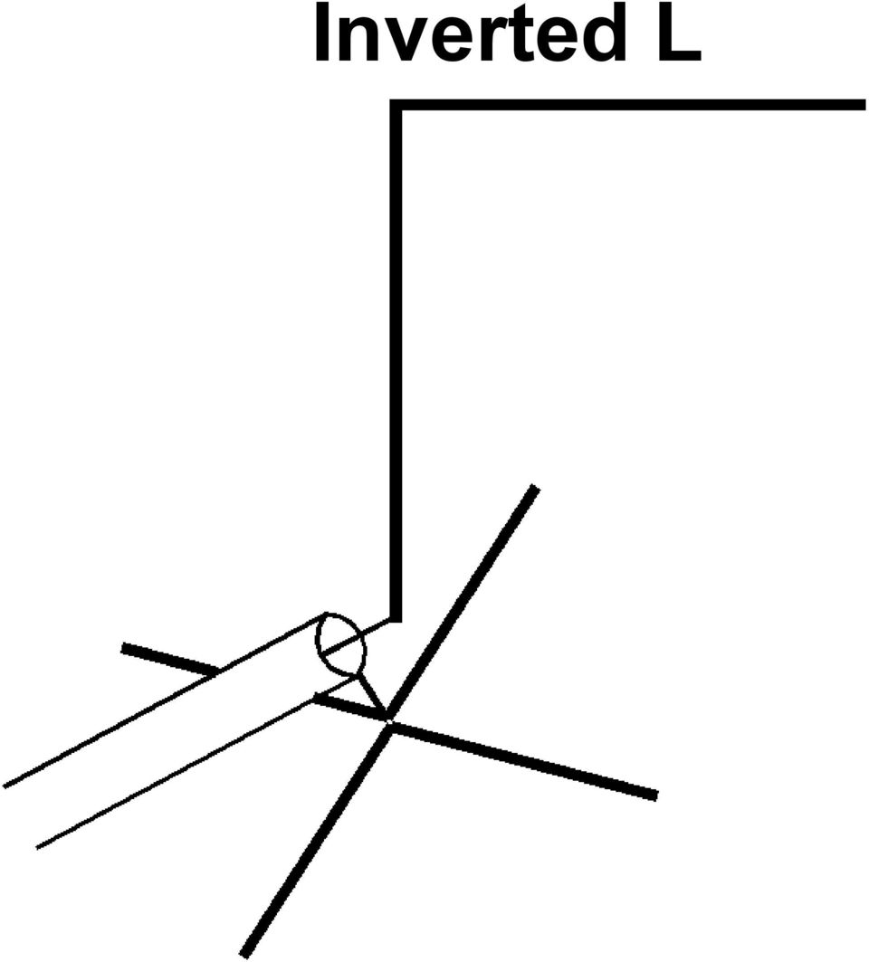
6 Good Vertical Antennas A straight quarter-wave (Best) λ/4 ~ 125 ft at 1830 khz with THHN Inverted L (Good) Go straight up as high as you can with a wire, then bend the remaining wire to run horizontal to resonate it Tee vertical (A bit better than L) Like an inverted L, but the top is extended in opposite directions
 Like an inverted L, but the top is extended in opposite")
7 Inverted L
8 Simple Tee Vertical

9 Other Vertical Radiators Shortened vertical with multiple top loading wires (capacity hat) Shortened vertical with capacity hat and bottom loading coil Shortened vertical with bottom loading coil Heliacal wound vertical (K6MM)

10 What is Loading? Loading is the modification of a short antenna so it looks longer to the transmitter (often resonant) Add series inductance At bottom or center of radiator Add horizontal wire(s) at the top Wires provide capacitance to earth

11 What is Top Loading? Bend top over (inverted L) Bend top both ways (Tee vertical) Add multiple wires to top Connect top guy wires to tower Length of guys to first insulator provides top loading Yagis on top of a tower add top loading (not insulated elements)

12 Why Top Loading Is Best Current is what produces radiation Current in a resonant vertical peaks near the feedpoint, and is zero at the far end Adding inductance near a current peak breaks it up and reduces radiation Added resistance near feedpoint burns more power (R of inductor) Bottom loading at the base works, but burns some power Using bigger wire helps (#10 good)
 Bottom loading at the base works, but burns some power Using bigger wire helps")
13 Making a Shorter Wire Resonant Use insulated wire (1-2%) Make the conductor thicker 2 or 3 wires spaced 6-12 inches apart, connected top and bottom (1-2%) Improves SWR bandwidth Not a lot, but every little bit helps

14 Good Inductors Are Easy Wind #10 THHN solid copper around 3-in or 4-in PVC conduit Drill holes for wires at each end to hold in place Extend wires to screws mounted to either end Drill more holes for antenna wires Loop antenna wire through holes, connect both wires at screws

15 160M Loading Coil 7 µh

16 Feedpoint of Sloping Vertical

17 Good Inductors Are Easy Use NEC to model antenna and predict inductance required to resonate the the antenna or: Use Vector Analyzer to measure feedpoint Z of existing antenna that s too short, export data to SimSmith and predict inductance Coil winding formulas in ARRL Handbook are very accurate

18 How Much Top Loading? Use NEC to predict Even a very simple model will get you close for the radiator Connect the bottom of the vertical wire to ground, add a source at the bottom, add the top loading wire(s) Plot SWR in 10 khz steps to find resonance Vary length of top wire(s) to set F R
 Plot SWR in 10 khz steps to")
19 Top Loading Guidelines Make the vertical as tall as you can for best efficiency Do what you can with left-over wire length at the top, either T or L Add loading coil at base if needed to make it easier to tune For an Inverted L, making the total wire length = λ/4 = 130 ft will get you close

20 How Earth Affects Verticals Power is lost in earth very near the antenna before it can be radiated Radials, counterpoise reduce this loss Radials, counterpoise make the most difference with poor soil

21 How Earth Affects Verticals Radiated signal is reflected by the earth far from the antenna Reflection adds to direct signal Shapes the vertical pattern Better soil helps low angle most Radials don t help the reflection, but they strengthen the radiated signal that gets reflected
22 What Kind of Soil Do I Have? Most of the Bay Area has Average soil Most of the North Bay has Good soil Most desert and very rocky areas are poor to very poor soil You can measure it see N6LF s website for a simple method
23 The Power of Earth Reflections Salt Water Very Good Soil Average Soil Rocky/Sandy Soil 0dB Vertical Pattern dB
24 Resistance Matters Radiation resistance (R R ) is the part of the feedpoint impedance that accounts for radiated power Mostly determined by vertical height of the radiator R R is good resistance, larger is good
25 Radiation Resistance vs Height λ/4 λ/8
26 Resistance Matters Ground resistance (R G ) combines with wire resistance (R G ) to burn transmitter power
27 It s A Simple Series Circuit CURRENT R R RADIATED POWER R W WIRE LOSS R G GROUND LOSS
28 Loss Resistance Matters P TRANS = P RAD +P WIRE +P GROUND P TRANS = I 2 R R + I 2 R W + I 2 R G Antenna Efficiency = R R /(R W +R G ) If (R W +R G ) = R R, loss is 3dB If (R W +R G ) = 2R R, loss is 6dB We want large R R, small R G
29 Ground Resistance Depends on the nature of the earth around the antenna We can t change it except by moving Depends on the radial system Make R G smaller by using more radials and longer radials a good counterpoise a ground screen
30 Tall Antenna, Good Radials CURRENT RADIATED POWER R R = 34 Ω R W = 1Ω WIRE LOSS R G = 7 Ω GROUND LOSS Loss = 0.8dB
31 Tall Antenna, Good Radials 100 W 83 Watts R R = 34 Ω R W = 1Ω 2 W R G = 7 Ω 15 W Loss = 0.8dB
32 Short Antenna, Limited Radials CURRENT R R = 6 Ω RADIATED POWER R W =.5Ω WIRE LOSS R G = 30 Ω GROUND LOSS Loss = 15 db
33 Short Antenna, Limited Radials 100W R R = 6 Ω 3 Watts R W =.5Ω.5 Watt R G = 30 Ω 96 Watts Loss = 15 db
34 Typical Loss Resistances R W of #10 wire ~1 Ω for λ/4 It s hard to get R G below 10 Ω with a lot of space, and 20 Ω is tough on a small lot So we usually ignore R W and concentrate on trying to make R G smaller and R R larger
35 Why Radials or Counterpoise? Earth is a relatively poor conductor that is, it s a (very big) resistor Even the best connection to earth is bad for an antenna it drives current to that lossy earth Current in lossy earth burns transmitter power (P G = I 2 R G ) before it can be radiated
36 Why Radials or Counterpoise? An ideal radial system: shields the antenna from the earth provides a path for return current Provides a return path for fields produced by the antenna A counterpoise provides only the return current path More about counterpoises later
37 Why Radials or Counterpoise? With no radials or counterpoise, the outside of the coax forms a single radial or counterpoise It s better than nothing, but not very effective And it can put RF in the shack
38 Guidelines for All Radials Insulated wire holds up longer #18 minimum size for durability Large spools hard to buy #14 THHN (house wire) works well Mass market items often less inexpensive and easy to find Discount for 6 or more spools at big box stores (Home Depot, Lowe s)
39 On-Ground Radial Systems Best up to 60 λ/4 wires (shortened by V F to 100 ft) laid out as symmetrically as you can Very Good many wires on the ground, lengths can be random Symmetry is good, but most radial systems must be shorter in some directions because they run into buildings, roads, property lines
40 Resonant Radial Length 1830 khz Average Soil
41 Velocity Factor (V F ) vs Height
42 Traditional Radial Systems 60 radials, each ft long, arranged symmetrically around the feedpoint That requires that we can rig our antenna in the center of open space with a 100 ft radius
43 Traditional Radial Systems 60 radials, each ft long, arranged symmetrically around the feedpoint That requires that we can rig our antenna in the center of open space with a 100 ft radius Show of hands how many can do this?
44 Resonant Radials are Great, But: Few city and suburban lots are larger than 130 ft x 40 ft, most are smaller, and that includes a home and garage So most of us need a plan B (or C)
45 Three Limited Space Options Use as many radials as you can, each as long as will fit your space Use a ground screen made from galvanized hardware cloth as large as can reasonably fit in the space around your antenna Use a K2AV folded counterpoise 66 ft long, centered at base of antenna, suspended at 8 ft
46 On-Ground Radial Guidelines Don t use radials longer than the vertical height of your antenna Current distribution makes them not work very well If you want to use more wire, add more radials, not longer ones
47 On-Ground Radial Guidelines It s better to have more shorter radials than a few long ones You can never have too many Start with what you can do now, add more when you can Resonant length matters if you have only a few radials (<12), much less important if you have many
48 Should Radials Be Buried? Performance is about the same buried or laying on the ground Buried radials tend to be more stable with changes in weather Burial may offer some protection Radials laid on the ground will be overgrown by grass and brush
49 Cost/Benefit Analysis Question #1: What radial layouts give the most bang for the buck? Question #2: How much bang do I get from my buck? Question #3: How much is enough? Answers to all three questions It depends a lot on your soil It depends on R R
50 Optimum Use of Wire On / In Ground #14 Insulated THHN (House Wire) Radials Length (Ft) Total Wire (Ft, $) Loss (db) R IN Ohms ,550 2,800 6,200 11,500 $66 3 $124 $224 $496 $ Loss and Feedpoint impedance are for λ/4 vertical over average soil (K4ERO, Dec 76, ARRL 2010 Handbook)
51 SWR and Ground Losses It s quite difficult to get ground and wire losses below about 4 Ω, and R R above 35 Ω At the feedpoint, we re measuring R R + R W + R G As ground losses are reduced (more radials) SWR rises In this case, higher SWR is good!
52 Optimum Use of Wire On / In Ground #14 Insulated THHN (House Wire) Radials Length (Ft) Total Wire (Ft, $) Loss (db) R IN Ohms ,550 2,800 6,200 11,500 $66 3 $124 $224 $496 $ Loss and Feedpoint impedance are for λ/4 vertical over average soil (K4ERO, Dec 76, ARRL 2010 Handbook)
53 Optimum Use of Wire On/In Ground K3LC λ/4 vertical over average soil Radials Length (Ft) Total Wire (Ft, $) 500 $40 1,000 $80 2,000 $160 4,000 $320 8,000 $640 Gain (dbi) National Contest Journal March/April 2004 Computed from NEC4 Model
54 Optimum Use of Wire On/In Ground K3LC λ/4 vertical very poor soil Radials Length (Ft) Total Wire (Ft, $) 500 $40 1,000 $80 2,000 $160 4,000 $320 8,000 $640 Gain (dbi) National Contest Journal March/April 2004 Computed from NEC4 Model
55 Ground Screens Can Work Some AM broadcasters use a heavy copper mesh, typically 40 ft square surrounding the tower, with radials connected at perimeter of the mesh Provides very effective shielding between antenna and earth where current density and magnetic fields are strongest
56 Some Ground Screen Solutions Use strips of 3-ft or 5-ft wide galvanized hardware cloth ~ $350 for 600 sq ft, 19-gauge Or strips of galvanized welded wire fencing 2 x 2 or 2 x 4 grid ~ $ 150 for 600 sq ft, 14 gauge Or strips of galvanized wire mesh, 1 x 1 squares
57 ½ Galvanized Hardware Cloth
58 1-in x 1-in Galvanized Wire Mesh
59 Some Ground Screen Solutions If possible, lay strips out radially in four directions Use alternative layouts when it s the best you can do A single strip, centered below the antenna if possible, or even two running parallel to each other More is better
60 Galvanized Hardware Cloth Sources of 19-gauge, 1/2 in grid 3 ft x 25 ft $50 Home Depot 3 ft x 50 ft $75 amazon.com 3 ft x 100 ft $108 Howard Wire, Hayward, CA (56#) Use a layout that fits your space 4-3 x 25 strips 300 sq ft 8-3 x sq ft 4-3 x 50 strips 600 sq ft
61 Galvanized Welded Wire Fencing Home Depot, Lowe s, etc. Cheap! For 2 x 4 grid, 14 gauge 4-3 x 50 strips, 600 sq ft ~ $ x 50 strips, 800 sq ft ~ $ x 25 strips, 400 sq ft ~ $80 For 1 x 2 grid, 14 gauge (Ace) 4 2 x 25 strips 400 sq ft ~ $100 For 2 x 3 grid, 16 gauge (Ace) 4 3 x 50 strips 600 sq ft ~ $136
62 Using Galvanized Wire Mesh Can be on the ground or buried Don t try to solder to it, use mechanical connections Avoid damage to the galvanizing Join overlapping or adjacent strips at multiple points All of these mesh options are OK for our purposes
63 Galvanized Wire Mesh Decent alternative to radials Compare 4 4 ft x 50 ft mesh strips to 60 radials the same length Much higher density close to antenna where loss is greatest Less density further from antenna Performance could be close
64 Counterpoise Systems Any end-fed antenna needs a path for return current, and for the fields produced by the antenna Radial systems are best, but not always practical A counterpoise is what we call another conductor that can sink the return current (but may not help much with the fields)
65 My Counterpoise in Chicago The Shack The Fence
66 160M Top-loaded Wire in Chicago The Fence
67 K2AV Folded Counterpoise Designed as a solution for small lots only 66 ft long x 8 ft high Easy to build Folded design places currents in overlapping segments out of phase with each other, so fields coupling to the earth partially cancel, reducing earth losses
68 K2AV Folded Counterpoise Dimensions for #12 bare or enameled copper, spaced 4 inches, 8 ft high Use 1/2 inch PVC conduit for spreaders
69 K2AV Folded Counterpoise K2AV says it s roughly equal to 4 elevated radials Requires 1:1 transformer, or K9YC feedline choke and loading coil
70 K2AV Matching / Isolation Xfmr A version of this transformer is sold by Balun Designs ($83 + shipping). The K9YC method is much cheaper
71 K2AV s Matching Method 12 bifilar turns #12 Teflon, on Amidon T300A-2 #2 powdered iron core, connected as a transformer, not a choke
72 Transformer in Box By K8OZ
73 K2AV Folded Counterpoise K2AV says the FCP is ineffective without an isolation transformer, and that a ferrite choke will fry He s partly right, but there s more to it.
74 W8JI s Analysis (Using NEC) The counterpoise is electrically short (< λ/4), so it needs series L The K2AV-designed transformer has enough leakage inductance to provide that series L The series L makes the FCP work better, and the transformer keeps common mode current off the coax
75 K9YC s Analysis ( based on W8JI s) The required series L can easily be provided by a simple loading coil wound on 4-inch PVC conduit Any of my common mode chokes designed for 160M will keep RF off the coax Both the inductor and the choke are needed with no inductor, the antenna is badly unbalanced, and the choke will fry at high power
76 K9YC s Analysis ( based on W8JI s) Adding series L, either with the transformer or a loading coil provides the balance W8JI says X C = 195Ω, so needed L is ~ 17µH, 13 close-wound turns of #10 THHN on 4-inch PVC conduit Once the antenna is reasonably balanced, a good ferrite choke can handle the power
77 Add Loading Coil Here Add loading coil between counterpoise and coax shield and Add K9YC ferrite choke to feedline
78 Coax Choke for 160M
79 Coax Choke for 160M
80 Another Choke for 160M 20M 16 bifilar turns #12 THHN on #31 core, connected as parallel wire transmission line between coax and antenna
81 Using Your Tower on 160M Load it as a vertical See ARRL Handbook, ARRL Antenna Book for matching methods Gamma match Omega match Use tower to support one or more sloping wires, load the wire(s) Some can produce gain
82 Feeding a Tower on 160M Ham towers are electrically longer than their physical height Resonant frequency is lowered by Cross section of the tower Top-loading of the boom and noninsulated elements of yagi antennas Typical tri-bander or 3-el 20M Yagi is equivalent to ft height Less if some elements are insulated
83 Feeding a Grounded Tower Use NEC to find resonance Add to the model all antenna elements, including booms, that are electrically connected to the tower (but not insulated elements) Place a source at the base, connect base to ground, and compute SWR over the range of frequencies where you expect to find resonance
84 Tower Resonance An Example My 45 ft tower has: 17 ft mast above tower 3-el 20M Yagi at top of mast 4-el 15M Yagi 10 ft below top of mast Long boom 2M Yagi side-mounted just below rotator NEC predicts 2.1 MHz resonance
85 Feeding a Grounded Tower Using NEC to find resonance Equation for equivalent diameter of triangular tower D = Diameter of leg, F = face width 3 DF 2 2
86 Grounded Tower Needs Radials Base connected to lossy earth, is a poor RF ground Use on-ground or buried radials Radials also needed if you want tower to be a passive reflector No radials means high resistance in series with tower, reducing current, killing the gain it could provide Ground screen also an option
87 Hang A Sloping Vertical on Tower Mount 10 ft length 4-in PVC horizontally below rotator, use it to support sloping wire, insulated from tower Feed wire as a vertical, adding top or base loading as required Add radials, ground screen, or counterpoise at feedpoint
88 Hang A Sloping Vertical on Tower Depending on height, tower may act as passive reflector, providing gain in direction of slope If so, tower needs on-ground radials Follow on-ground guidelines I m getting nearly 5 dbi See K3LR s and N6LF s websites, ARRL Handbook, ARRL Antenna Book for more sloping wire ideas
89 What To Do With More Space? A few of us are lucky enough to have space I have 8 acres of redwoods I hang wires from trees, run radials, both elevated and on the ground through the woods Watch out for interaction. That 45 ft tower interacts with my 160M verticals, changing their pattern!
90 On-Ground Radial Guidelines Use taller antenna, more and longer radials Resonant length matters if you have only a few radials (<12), much less important if you have many ft is in the ballpark for THHN radials laying on the ground depends on soil conductivity, may vary throughout year with moisture
91 On-Ground Radial Guidelines Connect opposing radials in pairs to antenna impedance meter (MFJ259, etc.) to find their resonance Trim radials to make them resonant Lengthening effect of soil will be greatest when soil is wet, so do your first trim when soil is dry
92 Measured, 130 ft radials laying on average ground, λ/4 vertical 4 radials 8 radials 16 radials 32 radials 64 radials $42 $84 $168 $336 $672 0 db 0.8 db 1.2 db 2.1 db 2.4 db (Rudy Severns N6LF QEX Jul/Aug 09)
93 4 λ/4 radials or 100 λ/4 radials on ground how much difference? Over very good soil 3-4 db Over average soil 5-6 db Over poor soil 6-7 db Measured by N7CL at many varied sites as a consultant to broadcasters and the military Source: Topband reflector archives
94 Elevated Radial Systems Good Four λ/4 radials elevated at least 18 ft (not shortened by V F ) Better Increase number to 8-16 Height matters elevated radials don t work very well unless they are at least 16 ft high, higher better Symmetry matters differences can greatly increase loss
95 Symmetry of Elevated Radials Most important if only 4 radials Soil under radials varies, causes asymmetry Small differences can cause major imbalance in currents, greatly increasing ground loss Using more radials minimizes the effects of asymmetry
96 To Minimize Asymmetry Losses Connect elevated radials only to coax shield, never to ground rod Always use a serious ferrite choke on the coax Insulate the ends up to 2 kv can be present at high power
97 Elevated Radials in Limited Space Shorter radials can work if: There are many of them They are equal in length They are equal in height They are equally spaced They are high (at least 16 ft) If you can t satisfy this, use onground radials, wire mesh, or a counterpoise
98 A Simple Match for a Longer Wire As a wire is made longer than λ/4, R R gets larger and the antenna looks inductive If space permits, rig a wire long enough that R R + R W + R G = 50Ω Add a series capacitor to tune out the inductance Use HV capacitors from HSC if you want to run high power
99 How Much Capacitance? Method #1: In NEC model, find X when R = 50Ω, compute C Method #2: Measure feedpoint Z to get X, compute C Method #3: Trial and error add series C until SWR = 1:1 All three work, #1 and #2 are faster and less work
100 Capacitors to Handle High Power An important characteristic of any capacitor is it s Equivalent Series Resistance (ESR) ESR burns power (I 2 R) current is highest at the feedpoint, so cap with high ESR will fry Caps with higher voltage rating may have lower ESR, but not always
101 Capacitors to Handle High Power HSC has a good selection of HV disc ceramic caps, but not all have low ESR They re cheap, so buy a selection and try them Add caps to resonate the antenna, transmit keydown for a while, stop transmitting, and feel the cap If cap(s) are cool (or slightly warm), ESR is low enough
102 Capacitors to Handle High Power Temperature coefficient (TC) How much capacitance change in parts per million per degree C N750 = -7.5% for 100 C temp rise NPO = no change (expensive) Good low cost HV caps often have a high TC, work fine if low ESR Resonance goes up slightly winter to summer, or if the cap gets hot
103 Some High Voltage Caps That Work Well Good, inexpensive Better, but cost more
104 How Important is Matching? Losses on 160M are quite low in any decent RG8, even when not perfectly matched (~ 0.25dB/100 ft) A 3:1 match at the antenna is plenty good enough unless the run is quite long (>250 ft) with a decent tuner in the shack Worry about matching only to make your power amp happy
105 Receiving Antennas You can t work them if you can t hear them All serious 160M operators take RX antennas seriously Loop and flag antennas reject some noise, some have directivity
106 Receiving Antennas These are best if there s space Beverages Phased arrays of verticals For limited space K9AY loop, Waller flag N6RK has a nice feed system for magnetic loop
107 References ARRL Handbook ARRL Antenna Book ON4UN Low Band Dxing N6LF website N6RK website K9AY loop
108 References Waller Flag K3LR Website K9RS 2008 Dayton Antenna Forum NC0B 2009 Dayton Antenna Forum NC0B on Ground Screens (Ham Radio May 1977)
109 Working 160M From a Small Lot (and Larger Ones Too) Jim Brown K9YC k9yc@arrl.net
Basic Wire Antennas. Part II: Loops and Verticals
 Basic Wire Antennas Part II: Loops and Verticals A loop antenna is composed of a single loop of wire, greater than a half wavelength long. The loop does not have to be any particular shape. RF power can
Just a Dipole. Gary Wescom N0GW July 16, 2007
 Just a Dipole Gary Wescom N0GW July 16, 2007 Often we will hear people describing their antennas as just a dipole. After all, a coax cable fed, half wavelength dipole is one of the simplest antennas to
Cheap Antennas for the AMSAT LEO's Kent Britain -- WA5VJB
 Cheap Antennas for the AMSAT LEO's Kent Britain -- WA5VJB Cheap LEO Antenna Drew, KO4MA, using the Cheap LEO antenna during a Dayton AMSAT LEO Demonstration Hand held dual band antennas are popular for
Technician Licensing Class
 Technician Licensing Class Antennas Presented by Amateur Radio Technician Class Element 2 Course Presentation ELEMENT 2 SUB-ELEMENTS (Groupings) About Ham Radio Call Signs Control Mind the Rules Tech Frequencies
Weekend Antennas No. 1 A Bobtail Curtain for 2m
 Weekend Antennas No. 1 A Bobtail Curtain for 2m Welcome to the first installment of my new column, which I hope will become a regular feature in Radio ZS. Each installment will present a practical and
Newcomers and Elmers Net: More Wire Antennas 02.14.16 Robert AK3Q
 Newcomers and Elmers Net: More Wire Antennas 02.14.16 Robert AK3Q Antenna Construction Supplies Antenna Construction Tools (Harbor Freight can be a good place to go) Wire Cutters; Pliers (regular and needle
Small HF Antennas - - -- - - - -- - - ! The Small Space and Big Antenna Dilemma! Constraints
 Small HF Antennas! The Small Space and Big Antenna Dilemma! Constraints " Covenants " Restricted lot size " City Bylaws " Boards of Variance " Strata Rules " Neighbor complaints of unsightly structures
40m-10m DELTA LOOP ANTENNA - GU3WHN
 This simple broad band antenna is easy to build, has gain similar to that of a dipole and is tolerant of nearby objects. It can be erected in almost any configuration provided the wires are well separated
LDG RBA-4:1Balun LDG RBA-1:1Balun
 LDG RBA-4:1Balun LDG RBA-1:1Balun Table of Contents Features 1 Specifications 1 Preparation 2 An important word about power levels: 2 Installation 2 Care and Maintenance 6 Technical Support 6 Warranty
PLEASE - Read this entire booklet and study the diagrams before building a Quad, it can save you unwarranted frustrations!
 VHF/UHF Quad Antenna The information in this article has come from many amateur sources, the most notable was from WA6TEY (sk 1985) Ray Frost, who was a pioneer of VHF Quad designs and one of the best
VE3MLB Phased Double V Antenna for 75/80 Meter Band
 Jan. 17, 2008 VE3MLB Phased Double V Antenna for 75/80 Meter Band This is a story of a double inverted V antenna that I built in January 2008. I already had a full 80 meter Delta loop suspended from my
Installation Instructions Hustler 6-BTV Trap Vertical
 Installation Instructions Hustler 6-BTV Trap Vertical ASSEMBLY 1. Check the package contents against the parts list on page 2. 2. WARNING. Installation of this product near power lines is dangerous. For
My Loop Antenna. Stephen E. Sussman-Fort, Ph.D. AB2EW. stevesf@optonline.net
 Stephen E. Sussman-Fort, Ph.D. AB2EW stevesf@optonline.net Outline Brief History Characteristics of Small Loop Antennas for HF My Loop for 40m 15m Receive/Transmit Properties of Elect.-Small Loops Loop
40 Meter Mini-MOXON Beam Antenna. Designed, built, and presented by: Al Koblinski W7XA
 40 Meter Mini-MOXON Beam Antenna Designed, built, and presented by: Al Koblinski W7XA Design goals Some forward gain Good directivity (high F/B and F/S ratios) Relatively small size Good Bandwidth (min.
Invisible DX Antenna for the Low Bands
 Invisible DX Antenna for the Low Bands By Heinz-Josef Pick, DK5WL Summary This paper describes a multi-band DX antenna for the 160m-40m amateur radio bands with low visibility but great performance for
HF OPERATORS SMALL HF ANTENNAS - - - - - - - - - - - Rev 1. John White VA7JW
 HF OPERATORS SMALL HF ANTENNAS Rev 1 by John White VA7JW NSARC HF Operators 1 Antenna Problems Big or Small always problems. Affects all - Single family, apartments, condo s, high rises, etc The Small
Owners Manual For The PackTenna Mini
 Owners Manual For The PackTenna Mini By Nick Garner N3WG and George Zafiropoulos KJ6VU Quickstart With The 9:1 Random Wire Version You can identify this version because it has a yellow shrink wrap on the
DL-QRP-AG Lambda/2 no Counterpoise: Fuchs Antenna matching unit
 DL-QRP-AG Lambda/2 no Counterpoise: Fuchs Antenna matching unit QRPproject Molchstr. 15 12524 Berlin http://www.qrpproject.de Telefon: +49(30) 85 96 13 23 e-mail: support@qrpproject.de Handbucherstellung:
Using Sim Smith to Improve Antenna Matching
 Using Sim Smith to Improve Antenna Matching Jim Brown K9YC k9yc@arrl.net http://audiosystemsgroup.com/publish.htm The Objectives Eliminate antenna tuners Improve match to our rigs Minimize losses Improve
EH-20 20m antenna. By VE3RGW
 EH-20 20m antenna By VE3RGW Equivalent circuit of EH-20 (prototype 2A) antenna system. Upper cylinder Lower cylinder Ground Counter pose Phasing coil Impedance transformer and tune circuit Tune coil Feed
The Antenna Balun. What is this thing and why do I need it?
 What is this thing and why do I need it? The Antenna Balun In this chapter we will look at a common component in some transmission systems the balun. It is quite common to see a balun in wire antennas
2 Meter Half-Wave J-Pole Antenna From 450 Ohm Ladder Line
 2 Meter Half-Wave J-Pole Antenna From 450 Ohm Ladder Line Photos: Copyright 2007 David Jordan WA3GIN. All rights reserved. This is a good rainy day antenna project for those of you who would like to home
The Gamma Match. 1 Equal Size Elements
 The Gamma Match The gamma match was originally invented as a means of feeding vertical monopole antennas for medium wave broadcasts, which were earthed at the base for lightning protection (see Figure
ISS Minimalist Antenna
 ISS Minimalist Antenna The purpose of this project was to develop an antenna suggestion that would allow for a simple to duplicate, affordable antenna solution for reasonable access to signals transmitted
Antenna Basic Concepts
 ANTENNA An antenna is a device to transmit and/or receive electromagnetic waves. Electromagnetic waves are often referred to as radio waves. Most antennas are resonant devices, which operate efficiently
Selecting Receiving Antennas for Radio Tracking
 Selecting Receiving Antennas for Radio Tracking Larry B Kuechle, Advanced Telemetry Systems, Inc. Isanti, Minnesota 55040 lkuechle@atstrack.com The receiving antenna is an integral part of any radio location
Regional Emergency Communications. John Walters W8CX Alpena RACES
 Regional Emergency Communications John Walters W8CX Alpena RACES Regional Communications Needs 400 mile radius No skip zone; no dead spots No interference with or from broadcasters Reliable day/night coverage
An equivalent circuit of a loop antenna.
 3.2.1. Circuit Modeling: Loop Impedance A loop antenna can be represented by a lumped circuit when its dimension is small with respect to a wavelength. In this representation, the circuit parameters (generally
Understanding SWR by Example
 Understanding SWR by Example Take the mystery and mystique out of standing wave ratio. Darrin Walraven, K5DVW It sometimes seems that one of the most mysterious creatures in the world of Amateur Radio
Portable HF Antennas. Presented to the Stamford Amateur Radio Association. by Jon Perelstein. Copyright 2010 Jon Perelstein 1
 Portable HF Antennas Presented to the Stamford Amateur Radio Association by Jon Perelstein Copyright 2010 Jon Perelstein 1 For purposes of this presentation, a portable HF antenna is An antenna that doesn't
A 40M l/4 Vertical with Elevated Radials
 A 40M l/4 Vertical with Elevated Radials Easy to construct and raise by one person Larry Banks, W1DYJ First licensed: 1962 (KN1VFX) W1DYJ since 1966 Amateur Extra 10 Matthews Way Harpswell ME 33 Blueberry
Designing Log Periodic Antennas
 Designing Log Periodic Antennas By Glen Dash, Ampyx LLC, GlenDash at alum.mit.edu Copyright 2000, 2005 Ampyx LLC Lightweight and precise, the log periodic has become a favorite among EMC engineers. In
The VHF / UHF «Eggbeater» Antenna ~ Revisited ~
 The VHF / UHF «Eggbeater» Antenna ~ Revisited ~ ON6WG / F5VIF A new simple way to build the Eggbeater Antenna Introduction Previous designs described in «VHF / UHF «Eggbeater» Antenna ~ Part 1» and «VHF
Marine HF SSB Installation and Grounding. Anatomy of the Best Tour 2006
 Marine HF SSB Installation and Grounding Anatomy of the Best Tour 2006 Marine HF Installation Considerations This document is meant to be an overview of Marine HF radio installation For detailed installation
INSTALLATION INSTRUCTIONS HUSTLER 4-BTV, 5-BTV TRAP VERTICAL WARNING INSTALLATION OF THIS PRODUCT NEAR POWER LINES IS DANGEROUS
 INSTALLATION INSTRUCTIONS HUSTLER 4-BTV, 5-BTV TRAP VERTICAL WARNING INSTALLATION OF THIS PRODUCT NEAR POWER LINES IS DANGEROUS FOR YOUR SAFETY, FOLLOW THE INSTALLATION DIRECTIONS GENERAL DESCRIPTION:
Modeling an 80/40/20M Fan Dipole for DX
 Modeling an 80/40/20M Fan Dipole for DX New Station New Antennas! Installation and SWR Response Where is the DX? How do these Dipoles Play? (EZNEC) What about Terrain? HFTA and Terrain The effect on these
There are at least six ways to go about loading a short vertical monopole.
 With a mobile installation and most base locations, the HF seems to pose problems especially using the top band. 160 meters is also known as the top band. It is the only frequency group in the MF band
Coaxial Transmitting Chokes
 Coaxial Transmitting Chokes Jim Brown K9YC Santa Cruz, CA http://audiosystemsgroup.com Understanding Common Mode and Differential Mode Currents on Transmission Lines 1 Differential Mode Current Transmission
Single Transistor FM Transmitter Design
 Single Transistor FM Transmitter Design In telecommunications, frequency modulation (FM) conveys information over a carrier wave by varying its frequency. FM is commonly used at VHF radio frequencies for
The spiderbeam was developed as a DXpeditioner's dream antenna. It is a full size lightweight tribander yagi made of fiberglass and wire.
 The spiderbeam was developed as a DXpeditioner's dream antenna. It is a full size lightweight tribander yagi made of fiberglass and wire. The whole antenna weight is only kg (lbs), making it ideally suited
Impedance Matching and Matching Networks. Valentin Todorow, December, 2009
 Impedance Matching and Matching Networks Valentin Todorow, December, 2009 RF for Plasma Processing - Definition of RF What is RF? The IEEE Standard Dictionary of Electrical and Electronics Terms defines
Inverted L vs. Vertical T antennas At the search of the best Tx antenna for a low-latitude location
 vs. Vertical T antennas At the search of the best Tx antenna for a lowlatitude location By Pierluigi Luis Mansutti IV3PRK After having learnt which are the effects of the Earth s magnetic field on 160
NATIONAL TYPE MB-40SL MULTI-BAND TANK 9/29/1953
 NATIONAL TYPE MB-40SL MULTI-BAND TANK 9/29/1953 1. GENERAL The MB-40SL tanks is intended for use in grid circuits with approximately 20 Watts input and in final plate tank circuits of transmitters when
ZS6BKW vs G5RV. Antenna Patterns/SWR at 40 ft Center height, 27 ft end height ~148 Degree Included Angle
 ZS6BKW vs G5RV Antenna Patterns/SWR at 40 ft Center height, 27 ft end height ~148 Degree Included Angle Compiled By: Larry James LeBlanc 2010 For the AARA Ham Radio Club Note: All graphs computed using
Antennas 101 The Basics. Ward Silver NØAX
 Antennas 101 The Basics Ward Silver NØAX The Basics - 1 Antennas radiate (or receive) because electrons are accelerated (or are caused to accelerate) in the antenna s elements Radio or electromagnetic
EE302 Lesson 14: Antennas
 EE302 Lesson 14: Antennas Loaded antennas /4 antennas are desirable because their impedance is purely resistive. At low frequencies, full /4 antennas are sometime impractical (especially in mobile applications).
Efficient 2 meter Disguise Antenna Made From a TV Satellite Dish
 Efficient 2 meter Disguise Antenna Made From a TV Satellite Dish This horizontal slot antenna, cut into the reflector of a TV dish, is both the master of disguise and high in performance. By John Portune
VEC-896 Vertical Antenna
 VEC-896 Vertical Antenna INTRODUCTION The basic 40 meter quarter wave vertical antenna is 33' tall and requires a reasonably good ground or counterpoise system to function properly. The usual way to eliminate
THE OCF FD4 (FD3) WINDOM ANTENNA
 WINDOM ANTENNA") THE OCF FD4 (FD3) WINDOM ANTENNA FD4 (80/40/20/10 m) The 4-band Fritzel model FD4 is a special version of a Windom antenna. It is a half-wave long on the lowest frequency, and is fed from a coax cable
THE OCF FD4 (FD3) WINDOM ANTENNA FD4 (80/40/20/10 m) The 4-band Fritzel model FD4 is a special version of a Windom antenna. It is a half-wave long on the lowest frequency, and is fed from a coax cable
STACKING, PHASING and MATCHING YAGIS
 STACKING, PHASING and MATCHING YAGIS This is a synopsis of a talk presented to the Sydney VHF DX GROUP on Tuesday March 16th 1999 by Gordon McDonald VK2ZAB. QUESTIONS When the stacking of Yagis is being
Antenna Deployment Technical Brief
 ProCurve Networking Antenna Deployment Technical Brief Introduction... 2 Antenna types... 2 Omni directional antennas... 2 Directional antennas... 2 Diversity antennas... 3 High gain directional antennas...
impedance is easier for the tuner to cope with across multiple bands which are related to even harmonic lengths of the dipole.
 By Ron Bertrand VK2DQ - 2007 Want to build a simple, efficient, multiband antenna? One of the best and inexpensive multiband antennas is the off-centre-fed (OCF) dipole. These are wonderfully simple antennas
Constructing a precision SWR meter and antenna analyzer. Mike Brink HNF, Design Technologist.
 Constructing a precision SWR meter and antenna analyzer. Mike Brink HNF, Design Technologist. Abstract. I have been asked to put together a detailed article on a SWR meter. In this article I will deal
UNDERSTANDING AND CONTROLLING COMMON-MODE EMISSIONS IN HIGH-POWER ELECTRONICS
 Page 1 UNDERSTANDING AND CONTROLLING COMMON-MODE EMISSIONS IN HIGH-POWER ELECTRONICS By Henry Ott Consultants Livingston, NJ 07039 (973) 992-1793 www.hottconsultants.com hott@ieee.org Page 2 THE BASIC
Introduction to the Smith Chart for the MSA Sam Wetterlin 10/12/09 Z +
 Introduction to the Smith Chart for the MSA Sam Wetterlin 10/12/09 Quick Review of Reflection Coefficient The Smith chart is a method of graphing reflection coefficients and impedance, and is often useful
Iron Powder Cores for Switchmode Power Supply Inductors. by: Jim Cox
 HOME APPLICATION NOTES Iron Powder Cores for Switchmode Power Supply Inductors by: Jim Cox Purpose: The purpose of this application note is to cover the properties of iron powder as a magnetic core material
NVIS ANTENNA THEORY AND DESIGN
 NVIS ANTENNA THEORY AND DESIGN Introduction A properly designed Near Vertical Incident Skywave (NVIS) antenna will have a directivity pattern that will maximize transmission and reception at high angles
The W5JCK Guide to the Mathematic Equations Required for the Amateur Extra Class Exam
 The W5JCK Guide to the Mathematic Equations Required for the Amateur Extra Class Exam This document contains every question from the Extra Class (Element 4) Question Pool* that requires one or more mathematical
Odyssey of the Mind Technology Fair. Simple Electronics
 Simple Electronics 1. Terms volts, amps, ohms, watts, positive, negative, AC, DC 2. Matching voltages a. Series vs. parallel 3. Battery capacity 4. Simple electronic circuit light bulb 5. Chose the right
Antenna Glossary Before we talk about specific antennas, there are a few common terms that must be defined and explained:
 Antenna Basics Introduction Antennas are a very important component of communication systems. By definition, an antenna is a device used to transform an RF signal, traveling on a conductor, into an electromagnetic
Application Note. So You Need to Measure Some Inductors?
 So You Need to Measure Some nductors? Take a look at the 1910 nductance Analyzer. Although specifically designed for production testing of inductors and coils, in addition to measuring inductance (L),
Cheap Yagi Antennas for VHF/UHF
 Cheap Yagi Antennas for VHF/UHF by Kent Britain, WA5VJB edited by John Maca, AB5SS [Editors notes: The antennas described in this article were built as the result of several discussions between Kent and
Since any real component also has loss due to the resistive component, the average power dissipated is 2 2R
 Quality factor, Q Reactive components such as capacitors and inductors are often described with a figure of merit called Q. While it can be defined in many ways, it s most fundamental description is: Q
MAGNETICS: FERRITES, BEADS and BALUNS
 HF OPERATORS MAGNETICS: FERRITES, BEADS and BALUNS by John White VA7JW NSARC HF Operators 1 What s the Problem?! HF Dipoles and coaxial cables have a nasty compatibility problem! Dipoles are balanced structures!
Video Camera Installation Guide
 Video Camera Installation Guide The intent of this guide is to provide the information needed to complete or modify a video camera installation to avoid lightning and induced power surge damage. This guide
The Critical Length of a Transmission Line
 Page 1 of 9 The Critical Length of a Transmission Line Dr. Eric Bogatin President, Bogatin Enterprises Oct 1, 2004 Abstract A transmission line is always a transmission line. However, if it is physically
Antennas that provide a good impedance match over a wide frequency range have been a
 Chapter 9 Broadband Antennas Antennas that provide a good impedance match over a wide frequency range have been a topic of interest to hams for many years. The advantages of a broadband antenna are obvious
CUSHCRAFT R5 (10/12/15/17/20 m) POWER PRACTICAL TESTS INSULATOR
 POWER PRACTICAL TESTS INSULATOR") onhr5engres Page 1 of 6 Cushcraft R5 ½ λ Vertical Maintenance and Repair CUSHCRAFT R5 (10/12/15/17/20 m) Cushcraft have made many vertical antennas; R4, R5, R6, R6000, R7, R7000, R8 etc. All are ½ wave
onhr5engres Page 1 of 6 Cushcraft R5 ½ λ Vertical Maintenance and Repair CUSHCRAFT R5 (10/12/15/17/20 m) Cushcraft have made many vertical antennas; R4, R5, R6, R6000, R7, R7000, R8 etc. All are ½ wave
Embedded FM/TV Antenna System
 1 Embedded FM/TV Antenna System Final Report Prepared for By January 21, 2011 2 Table of Contents 1 Introduction... 5 2 Technical Specification... 6 3 Prototype Antenna... 7 4 FASTROAD Active module fabrication...
Loop Skywire Mysteries Explained?
 Introduction: Many antenna books dismiss the horizontal loop or loop skywire as a non performer. However user s of the loop will tell you that it does work; why? I used 80 & 40m loops in the past with
Broadband Terminated Vee Beam Wire Antenna
 Broadband Terminated Vee Beam Wire Antenna TEN-TEC Model 3402 and 3403 1.8-54 or 3.5-54 MHz. THROW AWAY YOUR ANTENNA TUNER! Models 3402 and 3403 are broadband terminated vee beam wire antennas. These broadband
Digital Systems Ribbon Cables I CMPE 650. Ribbon Cables A ribbon cable is any cable having multiple conductors bound together in a flat, wide strip.
 Ribbon Cables A ribbon cable is any cable having multiple conductors bound together in a flat, wide strip. Each dielectric configuration has different high-frequency characteristics. All configurations
'' EGGBEATER '' ANTENNA VHF/UHF ~ PART 2
 '' EGGBEATER '' ANTENNA VHF/UHF ~ PART 2 ON6WG / F5VIF Summary Note : In Part 1, Fig 1 shows a maximum gain of 6.45 dbi. Several design attempts were made using slightly different configurations ( i.e.
HUMAN EXPOSURE TO EMR: ASSESSMENT OF AMATEUR RADIO STATIONS FOR COMPLIANCE WITH ACA REQUIREMENTS
 HUMAN EXPOSURE TO EMR: ASSESSMENT OF AMATEUR RADIO STATIONS FOR COMPLIANCE WITH ACA REQUIREMENTS May 2005 Version 2.0 PO Box 78 BELCONNEN ACT 2616 Telephone (02) 6219 5555 Facsimile (02) 6219 5353 www.aca.gov.au
RigExpert AA-30 Antenna Analyzer (0.1 to 30 MHz) AA-54 Antenna Analyzer (0.1 to 54 MHz) User s manual
 AA-54 Antenna Analyzer (0.1 to 54 MHz) User s manual") RigExpert AA-30 Antenna Analyzer (0.1 to 30 MHz) AA-54 Antenna Analyzer (0.1 to 54 MHz) User s manual Table of contents 1. Description... 3 2. Specifications... 4 3. Precautions... 5 4. Operation... 6
RigExpert AA-30 Antenna Analyzer (0.1 to 30 MHz) AA-54 Antenna Analyzer (0.1 to 54 MHz) User s manual Table of contents 1. Description... 3 2. Specifications... 4 3. Precautions... 5 4. Operation... 6
Byonics Micro Trak 1000 High Altitude Balloon Tracker
 Byonics Micro Trak 1000 High Altitude Balloon Tracker The Micro Trak 1000 (MT 1000) is a high altitude balloon (HAB) tracker. It is usually sold as a combination to provide a simple, turn key tracking
Single Core Vs. Dual Core 4:1 Guanella BALUN
 Coax 12m Long and running straight down the pole. Not Grounded Coax straight down the pole B 12m Single Core BALUN (B5) Dual Core BALUN (B6) 21mA 7mA Comments: At this point, with just the antenna connected
Pillbox Antenna for 5.6 GHz Band Dragoslav Dobričić, YU1AW dragan@antennex.com
 Pillbox Antenna for 5.6 GHz Band Dragoslav Dobričić, YU1AW dragan@antennex.com Introduction The pillbox or cheese antenna is made of two parallel plates which are connected to the narrow strip of parabolic
High performance RX antenna for a small lot. Jose Carlos
 High performance RX antenna for a small lot Jose Carlos N4IS TX antenna interaction Common mode noise TX/RX leaking Polarization filter HWF Twisted pair lines HWF single loaded loop construction HWF dual
BALUNS PART I. Andy Griffith W4ULD
 BALUNS PART I Andy Griffith W4ULD Recently I was thumbing through my files on baluns and realized that over the years I had collected a wealth of information that could be of use to fellow Hams. So, I
Antenna Properties and their impact on Wireless System Performance. Dr. Steven R. Best. Cushcraft Corporation 48 Perimeter Road Manchester, NH 03013
 Antenna Properties and their impact on Wireless System Performance Dr. Steven R. Best Cushcraft Corporation 48 Perimeter Road Manchester, NH 03013 Phone (603) 627-7877 FAX: (603) 627-1764 Email: sbest@cushcraft.com
Building the HVPS High Voltage Power Supply
 Introduction Building the HVPS High Voltage Power Supply Voltages higher than the LVPS provides kilovolts are needed in later experiments to get strong electric fields and to generate microwaves. The high-voltage
HMS Hairpin Matching Systems
 HMS Hairpin Matching Systems DXE-HMS-1P, DXE-HMS-2P, DXE-HMS-4P DXE-HMS-INS-Rev 1b For Use with 1-1/2 Inch through 3 Inch Booms Shown with optional boom, elements and Element Bracket with hardware DX Engineering
Cumbria Designs T-1. SSB/CW Filter kit (4.9152MHz) User Manual
 User Manual") Cumbria Designs T-1 SSB/CW Filter kit (4.9152MHz) User Manual CONTENTS 1 INTRODUCTION 2 2 CIRCUIT DESCRIPTION 2 3 ASSEMBLY 2 4 TESTING 4 The Steading Stainton PENRITH Cumbria CA11 0ES UK 1 Introduction
Cumbria Designs T-1 SSB/CW Filter kit (4.9152MHz) User Manual CONTENTS 1 INTRODUCTION 2 2 CIRCUIT DESCRIPTION 2 3 ASSEMBLY 2 4 TESTING 4 The Steading Stainton PENRITH Cumbria CA11 0ES UK 1 Introduction
Power Supply V- Bonding, Hum, Buzz, and RFI Should We Bond V- at the Power Supply or Not? Jim Brown K9YC
 Power Supply V- Bonding, Hum, Buzz, and RFI Should We Bond V- at the Power Supply or Not? Jim Brown K9YC I've seen numerous anecdotal comments suggesting that all might not be right with the grounding
End Fed Antenna. Operating Manual. version 1.1
 Cross Country Wireless (2009) Ltd, 7 Thirlmere Grove, BOLTON, BL4 0QB, UK Email chrism@crosscountrywireless.net Web page http://www.crosscountrywireless.net Telephone +44 (0) 1204 410626 Mobile GSM 900
W8UM STATION EQUIPMENT DOCUMENTATION AMP-HF-SB-220. Date: 12/27/2006 Author: C. Galbraith KA8WFC Contact: (734) 678-2779
 678-2779") W8UM STATION EQUIPMENT DOCUMENTATION AMP-HF-SB-220 Equipment: Heathkit SB-220 HF Amplifier Scope: Description, Operation, History Date: 12/27/2006 Author: C. Galbraith KA8WFC Contact: cgalbrai@umich.edu,
W8UM STATION EQUIPMENT DOCUMENTATION AMP-HF-SB-220 Equipment: Heathkit SB-220 HF Amplifier Scope: Description, Operation, History Date: 12/27/2006 Author: C. Galbraith KA8WFC Contact: cgalbrai@umich.edu,
Physics 3330 Experiment #2 Fall 1999. DC techniques, dividers, and bridges R 2 =(1-S)R P R 1 =SR P. R P =10kΩ 10-turn pot.
R P R 1 =SR P. R P =10kΩ 10-turn pot.") Physics 3330 Experiment #2 Fall 1999 DC techniques, dividers, and bridges Purpose You will gain a familiarity with the circuit board and work with a variety of DC techniques, including voltage dividers,
Physics 3330 Experiment #2 Fall 1999 DC techniques, dividers, and bridges Purpose You will gain a familiarity with the circuit board and work with a variety of DC techniques, including voltage dividers,
"EGGBEATER"ANTENNA VHF/UHF ~ PART 1
 "EGGBEATER"ANTENNA VHF/UHF ~ PART 1 ON6WG / F5VIF For the enthusiastic listeners or the licensed amateur station wishing to experiment with satellite transmissions without investing a large sum of money
THE KW107 SUPERMATCH ATU manual, courtesy of Barry G0DWZ
 THE KW107 SUPERMATCH ATU manual, courtesy of Barry G0DWZ I ve copied the following directly from the KW107 manual without alteration. To clear up one or two ambiguous points, I have added my own comments
45. The peak value of an alternating current in a 1500-W device is 5.4 A. What is the rms voltage across?
 PHYS Practice Problems hapters 8- hapter 8. 45. The peak value of an alternating current in a 5-W device is 5.4 A. What is the rms voltage across? The power and current can be used to find the peak voltage,
Transmission Line Transformers
 Radio Frequency Circuit Design. W. Alan Davis, Krishna Agarwal Copyright 2001 John Wiley & Sons, Inc. Print ISBN 0-471-35052-4 Electronic ISBN 0-471-20068-9 CHAPTER SIX Transmission Line Transformers 6.1
Fundamentals of radio communication
 Fundamentals of radio communication This worksheet and all related files are licensed under the Creative Commons Attribution License, version 1.0. To view a copy of this license, visit http://creativecommons.org/licenses/by/1.0/,
Measuring Impedance and Frequency Response of Guitar Pickups
 Measuring Impedance and Frequency Response of Guitar Pickups Peter D. Hiscocks Syscomp Electronic Design Limited phiscock@ee.ryerson.ca www.syscompdesign.com April 30, 2011 Introduction The CircuitGear
MEDIUM WAVE DX ANTENNA
 THE HULA LOOP MEDIUM WAVE DX ANTENNA DESIGNED D BY SEAN GILBERT, G4UCJ The concept of the Hula Loop came after many years of building medium wave loops of varying size, shape and performance. Usually these
Shielding Effectiveness Test Method. Harbour s LL, SB, and SS Coaxial Cables. Designs for Improved Shielding Effectiveness
 Shielding Effectiveness Test Method Harbour s LL, SB, and SS Coaxial Cables Designs for Improved Shielding Effectiveness Harbour Industries 4744 Shelburne Road Shelburne Vermont 05482 USA 802-985-3311
Pipe-Cap Filters Revisited
 Pipe-Cap Filters Revisited Paul Wade W1GHZ 28 w1ghz@arrl.net Pipe-cap filters have been used in amateur microwave equipment for at least 2 years, but are still not well understood, and design information
BASIC ELECTRONICS AC CIRCUIT ANALYSIS. December 2011
 AM 5-202 BASIC ELECTRONICS AC CIRCUIT ANALYSIS December 2011 DISTRIBUTION RESTRICTION: Approved for Pubic Release. Distribution is unlimited. DEPARTMENT OF THE ARMY MILITARY AUXILIARY RADIO SYSTEM FORT
Oscillators. 2.0 RF Sine Wave Oscillators. www.learnabout-electronics.org. Module. RF Oscillators
 Module 2 www.learnabout-electronics.org Oscillators 2.0 RF Sine Wave Oscillators What you ll Learn in Module 2 Section 2.0 High Frequency Sine Wave Oscillators. Frequency Control in RF Oscillators. LC
5. ANTENNA TYPES. Figure 5. The vertical dipole and its electromagnetic equivalent, the vertical monopole
 Antennas can be classified in several ways. One way is the frequency band of operation. Others include physical structure and electrical/electromagnetic design. The antennas commonly used for LMR both