Bi-Xenon Retrofit DIY Instructions
|
|
|
- Kory Atkins
- 7 years ago
- Views:
Transcription
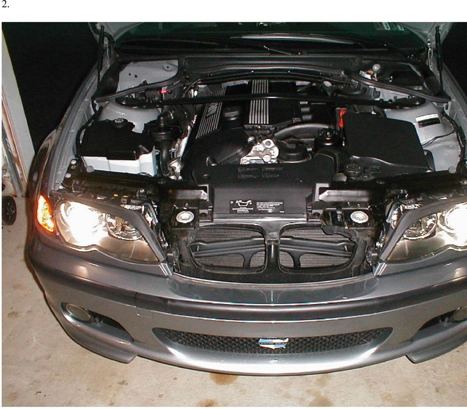
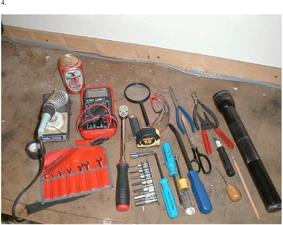
1 Bi-Xenon Retrofit DIY Instructions Models: Facelifted E46 with halogen lights fitted as OEM. NOTE: To get pre-2002 cars this functionality, you need to see the amendment. NOTE: Compliments of ScottZHP from Bimmerfest: Parts: BMW OEM parts: (qty 2) basemen shutter socket $ (qty 2) contact bushing for socket $ (qty 1) relay $ (qty 1) contact bushing for LCM $ (qty 2) warning label xenon lights $2.59 The next three part numbers were sourced from Radio Shack: (qty 1) 5 amp blade fuse $ (qty 1) blade fuse holder $ (qty 2) female disconnect lugs $1.69 The remaining bits were found laying around my garage: ¼ ring terminal for 16 gauge wire, found in toolbox. Copper crimping lug, see above. Misc lengths of 16gauge stranded wire (about 20 feet). Misc diams of heat shring tubing, 2 ft of corrugated wire wrap. Epoxy, Electrical tape, solder, wire ties, double sided tape. ¼-28 chrome plated acorn nut, ¼ star lock washer. Tools: Various hand tools, (see photo #1). Install time is about 1.5 hours, depending on your skill level. Prep work: 1. I was after a stealth looking install I wanted an OEM appearance. Take your time and the dealer will never notice the additional wiring. 2. Remove drivers side under-dash panel (3 Phillips-head screws, 1 twist nut near the pedals, 1 weird push pin at right knee, 2 slide clips under the steering wheel). 3. Remove the trim piece surrounding headlight switch (gently pry it
 5 amp blade fuse $1.39 2701213 (qty 1) blade fuse holder $2.29 6403039 (qty 2) female disconnect lugs $1.")
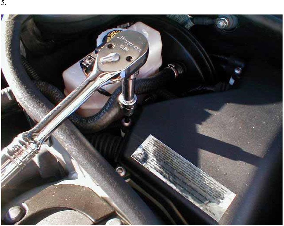
2 off from the drivers side using a rag around a thin blade screwdriver). 4. Remove the fuse box/relay rack cover under the hood on the drivers side using a? mm hex key, 5 mm maybe? (see photo #2). Wiring: The relay leads are as follows: 87 power output to shutter solenoid. 87 power output to shutter solenoid. (relay has two pins labeled 87) 30 power input for the relay 85 ground lug for relay coil; stud near air box. 86 bi-xenon activation for the relay coil; lead from pin 2 on the LCM 1. Carefully insert the contact bushings into the shutter socket plugs they only go in one way. (see photo #3). Use a magnifying glass if need be. Cover the leads with heat-shrinkable tubing, leaving about 6 in exposed. Shrink the tubing, but don t melt the wire. Set aside. 2.Solder a 2 ft long 16 gauge lead onto the LCM contact bushing end. This eventually connects to pin 86 on the relay. Cover the solder joint with heat shrink tube and shrink it. The shutters are controlled separately at the LCM, however we re only using a single relay for both shutters, so for our purposes we only need one lead. 3. Cut the cap off the fuse holder. Insert a 5 amp blade fuse. Epoxy the fuse-holder to the side of the relay with the part number on it (see photo #4). Cut one of the fuse holder leads to length of 4in. Slide heat shrink tube over the lead. Solder a female lug onto the lead. Slide the tube over the solder joint and shrink it. Plug this lug into pin #30 on the relay. Leave the other lead for later. 4. Prepare the remaining relay leads as follows: solder a female lug onto two 8ft lengths of 16 gauge wire. Don t forget the shrink tube. Connect both of these to pins #87 (the relay has two 87 pins). Solder another female lug onto a 4ft long 16 gauge wire. Connect this to pin 85. You should now have a harness that looks something like photo #4. 5. Set the harness aside. Have a beer.

3 Install 1. With the dash trim removed, unscrew the Phillips head screw securing the LCM and pull out the light switch module. Wiggle/pull as necessary, it will eventually come out. 2. Release the white clip holding the multi-pin connector to the LCM. Unplug it from the LCM. 3. Set the LCM aside. 4. Gently pry the sides of the LCM multi-pin connecter apart. 5. Slide the blue/brown plugs out of the plastic retainer (see photo #5). NOTE WHICH SIDE GOES WHERE in the connector. 6. Set the retainer aside. 7. CAREFULLY insert the LCM contact bushing into PIN #2 on the blue plug (see photo #6) insert ONLY as shown. Double check that it goes to pin #2. 8. Route and wire-tie the contact bushing wire lead into the LCM harness and fish it back into the foot well. 9. Reassemble the blue/brown plugs into the retainer. THEY ONLY GO IN ONE WAY, make sure to match the pin/plugs to the retainer. See photo # Plug the retainer into the LCM and snap the white collar over the connector. 11. Install the LCM; waste 10 minutes searching for the screw. 12.Fish the contact lead down into the drivers foot well and out the firewall adjacent to the harness, to the left (see photo #7, little red wire, right side halfway up). Be patient, it will eventually reappear in the relay rack under the hood. 13. Open the hood and remove the fuse box cover on the driver s side (if you have not done so already). 14. Gently wiggle the plastic tray upward in the relay rack. (see photo #8).
 insert ONLY as shown. Double check that it goes to pin #2. 8.")
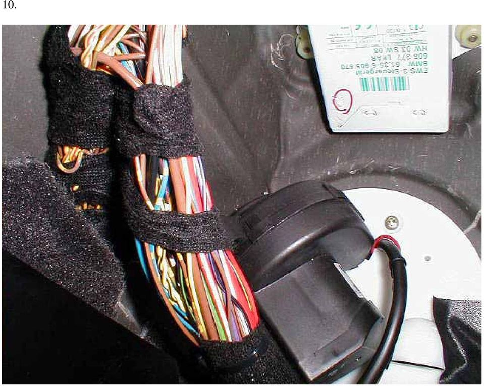
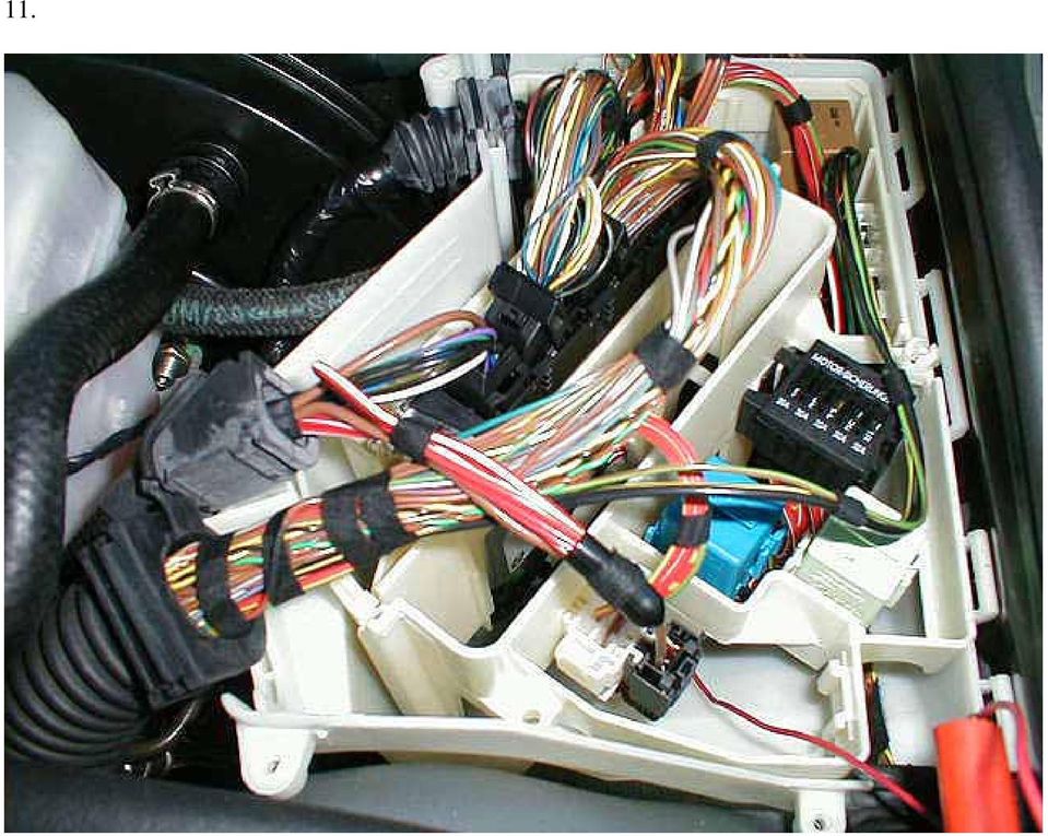
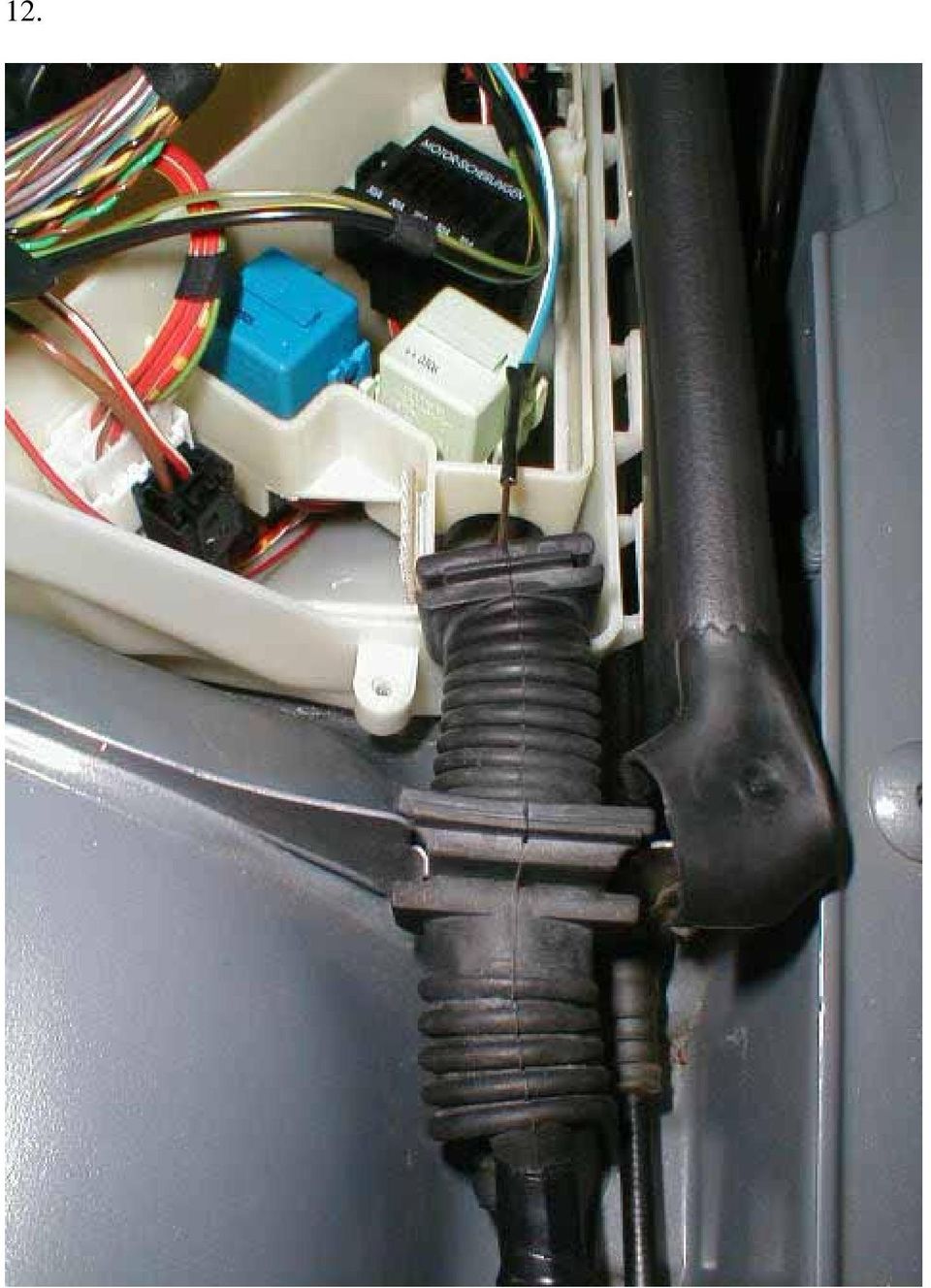
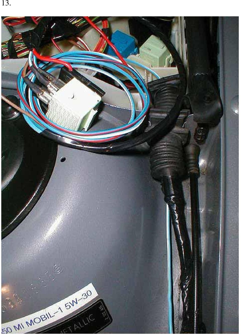
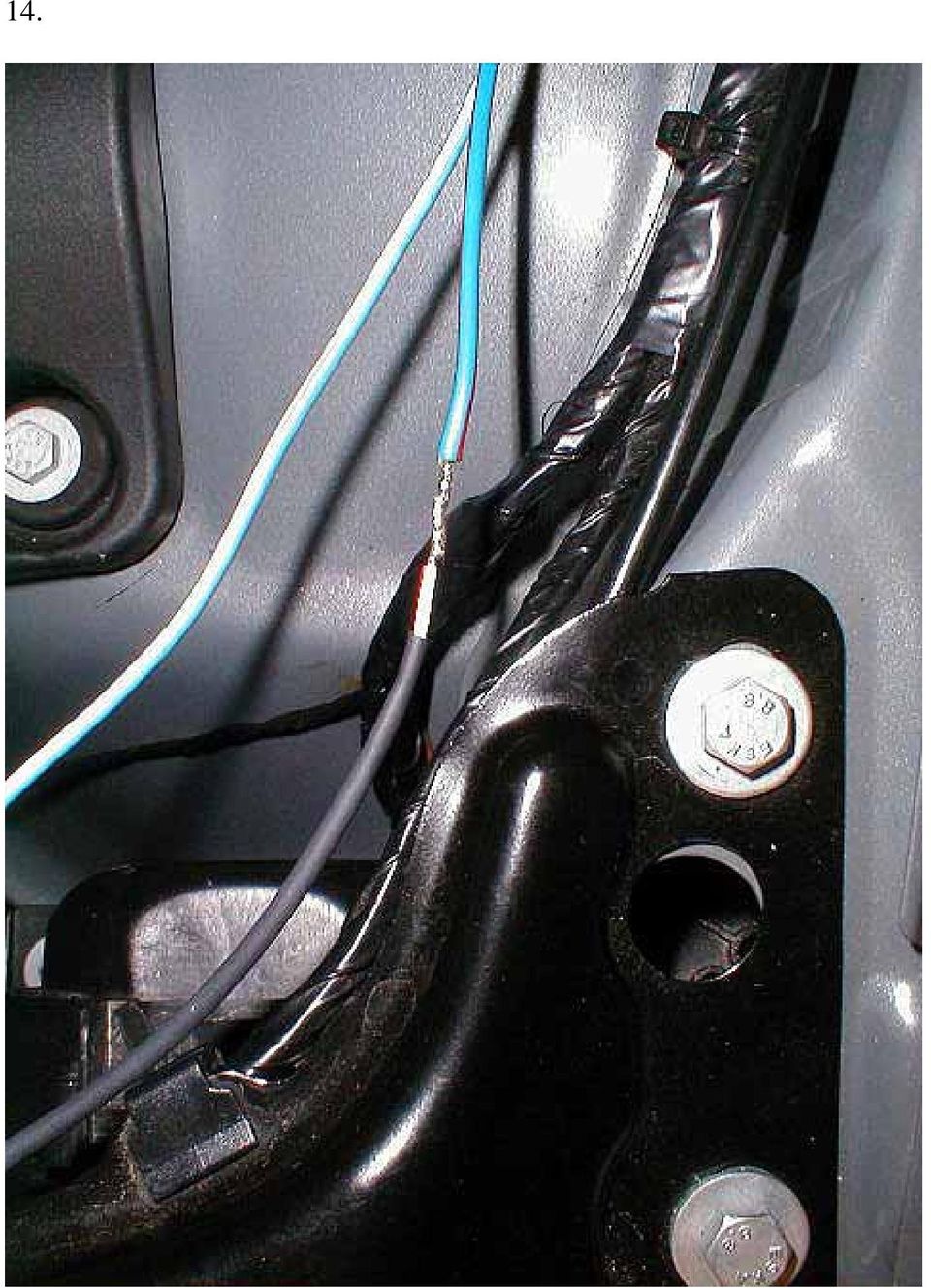
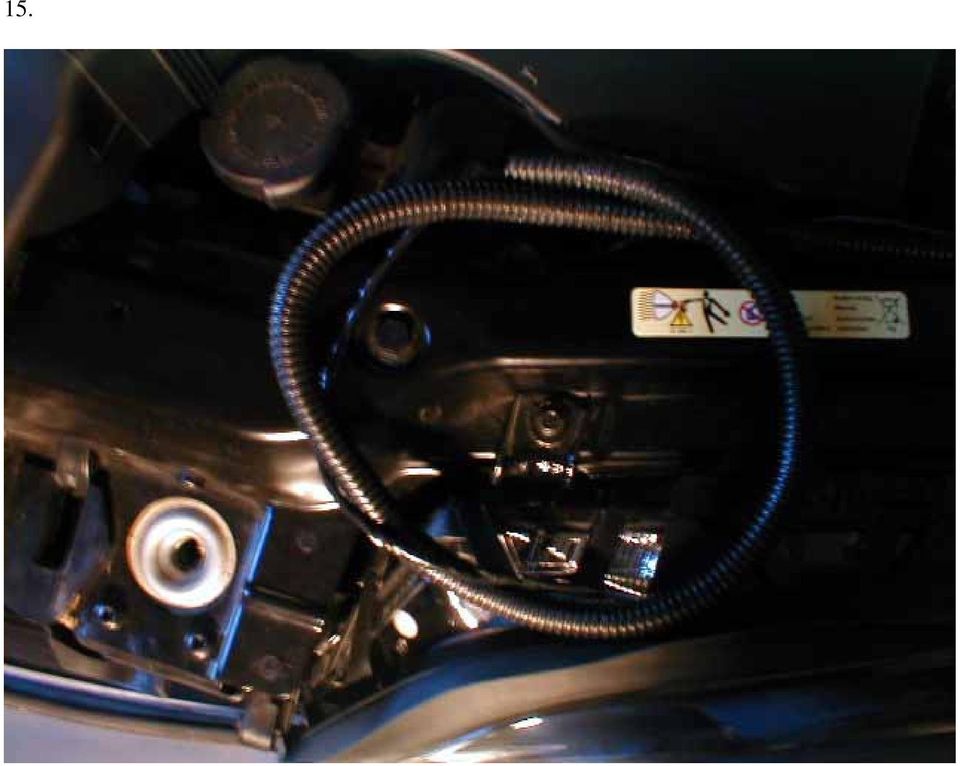
4 15. Loudly curse the insane Bavarian engineer who designed tray. 16. Locate the lead you just fished from the LCM and tape it to the side of the plastic tray near the front of the car. 17. Retrieve the relay from wherever you have stored it. Tape the 87 and 85 leads the entire length to make a cool looking harness. 18. Fish the two 87 leads and the 85 lead under the tray and out the corrugated rubber boot toward the headlights. See photo #9. I used the nipple underneath the rubber boot, as it was unused on my car.. First cut an X with an exacto knife. Tape the leads to MIG welding wire (or a coat hanger), and push them out the nipple. Pull remaining harness through leaving about 6 in to work with. (see photo #10). 19. Plug the sockets into the bi-xenon shutters on the ballast. 20. Cut the drivers side bi-xenon lead to length and solder it to one of the 87 leads. (see photo #11). Seal the solder joint with heat shrink tube (you did put the tube on, right?). 21. Remove the air snorkel and set is aside (pry the 3 pins upward and remove the pushpins and the retainers). 22. Insert the other lead 87 into a 2ft section of wire-wrap tubing. (see photo #12). 23. Fish the wire wrap tubing ABOVE the radiator, but underneath the radiator support brace (see photo #13). 24. Secure the wire-wrap tube with 3 wire-ties into the cutouts on the brace. 25. Reassemble the air snorkel. 26. Cut the passenger side bi-xenon lead to length and solder it to the other 87 lead; seal the solder joint with shrink tube. (see photo 14). 27. Locate the body jig stud adjacent to the airbox this will be the ground for the relay. Cut the 85 lead to length and solder a ¼ in round lug; seal the solder joint with heat shrink tube (see photo #15). Secure the lug with a ¼-28 nut and a star washer. Double nut it with a
, and push them out the nipple. Pull remaining harness through leaving about 6 in to work with.")
5 chrome plated acorn nut if you are a detail freak like me. 28. Have another beer and congratulate yourself; as you are nearly done. 29.Untape the LCM lead from the relay rack, trim to length and solder a female lug onto it. Connect this to pin 86 on the relay. This is the +ve lead to the relay coil. 30. Locate the 4 red/white wires crimped together in the fuse box/relay rack. Crimp the lead from the fuse holder (remember that lead?) to these (see photo #16#). I used a copper crimping connector because I had one laying around, but you may be able to just solder them together. Tape the connections (see photo 17). Testing 31. Get out your multimeter. ( a cheap meter is $10 from Harbor Freight, buy one, it is extremely handy). 32. Set the scale to 20vDC. Connect the ground lead of the meter to the lug near the airbox. DISCONNECT PIN 86 ON THE RELAY and connect it to the +ve lead on the meter. 33. Turn on the meter; it should read 0 volts. 34. Start the car and turn on the headlights. 35. Switch on the high beams. 36. The meter should read 12 volts. 37. If so, shut off the car. If not, you have a wiring issue. Retrace your connections, especially the ground. 38. Reconnect the LCM lead to pin Repeat steps 33 and Watch in awe as the bi-xenons operate. 41. Tidy up the leads in the fuse box/relay rack and reinstall cover (see photo #16). 42. Have another beer and admire the install (see photo #18) Enjoy
. Testing 31. Get out your multimeter.")
6 1.

7 2.
8 3.

9 4.
10 5.
11 6.

12 7.

13 8.

14 9.

15 10.
16 11.
17 12.
18 13.
19 14.
20 15.
21 16.
22 17.
23 18.
24 19.
25 20.
26 21.
A&A CORVETTE PERFORMANCE C6 BOOST & FUEL GAUGE INSTALLATION INSTRUCTIONS
 A&A CORVETTE PERFORMANCE C6 BOOST & FUEL GAUGE INSTALLATION INSTRUCTIONS 1. Check your gauges before you take them out of the packaging to make sure they are at 0 (zero) psi for both boost and fuel pressure.
Retrofit Instructions Installing a Sport Heated Steering Wheel - Leather, Multifunction BMW X5, E53, 2001 2006
 Retrofit Instructions Installing a Sport Heated Steering Wheel - Leather, Multifunction BMW X5, E53, 2001 2006 Disclaimer: This set of instructions is simply a guide on how I installed my own heated steering
Time needed: ~3h for lid replacement only. Add 1h for operation harness in lid and ~2h more for installing drive unit and cable harness in trunk.
 DIY for replacing trunk lid and/or retrofitting electrical operation of trunk lid. This document is meant to be a support and give advice on the procedure but I will take no responsibility for any damage
Installing RNS-E SAT NAV for Audi A4
 As one of the major options on the A4 you can get a DVD Satellite Navigation System call the RNS-E. With the help of ebay these sat nav systems are now available to by at a rough cost of 650 plus the cost
VW Jetta, Golf, New Beetle 1.9L TDi Unichip PnP Installation Instructions
 VW Jetta, Golf, New Beetle 1.9L TDi Unichip PnP Installation Instructions and Warranty Information Tools Required 10mm combination wrench, 13mm Socket (Jetta/Golf only), 3/8-inch or ¼-Inch drive ratchet,
INSTALLATION INSTRUCTIONS
 INSTALLATION INSTRUCTIONS Accessory Application Publications No. AII23628 2003 PILOT Issue Date MAY 2002 PARTS LIST Security System Kit (sold separately): P/N 08E51-S84-100 2 Remote controls Attachment
Solstice/Sky Water Pump Replacement
 Solstice/Sky Water Pump Replacement The water pump on the Solstice/Sky is starting to need replacement on some vehicles. This guide will help in replacing the water pump while the engine is still in the
by Myles H. Kitchen M.H. KITCHEN & ASSOCIATES www.auto-electronic.com (2002 X5 4.4 owner) March 2, 2004
 March 2, 2004") INSTALLING THE TEKONSHA PRODIGY ELECTRIC TRAILER BRAKE CONTROL IN THE BMW X5 by Myles H. Kitchen M.H. KITCHEN & ASSOCIATES www.auto-electronic.com (2002 X5 4.4 owner) March 2, 2004 INTRODUCTION The 2000
INSTALLING THE TEKONSHA PRODIGY ELECTRIC TRAILER BRAKE CONTROL IN THE BMW X5 by Myles H. Kitchen M.H. KITCHEN & ASSOCIATES www.auto-electronic.com (2002 X5 4.4 owner) March 2, 2004 INTRODUCTION The 2000
INSTALLATION INSTRUCTIONS
 INSTALLATION INSTRUCTIONS Accessory Application Publications No. AII 26327 2004 S2000 Issue Date OCT 2004 PARTS LIST Security System: P/N 08E51-S84-100 Attachment Kit: P/N 08E55-S2A-101 2 Remote controls
INSTALLATION INSTRUCTIONS
 Rear Vision System Aftermarket and Factory 5.0, 8.4 and 6.1 MyGig Touch Screen Display (Factory Display requires Chrysler/Dodge dealer to activate) 2009 Current* Dodge Ram (Kit part number 1009-6503) *NOTE:
Installation Instructions
 Installation Instructions Page 1 of 16 January 2008 Equipment Parts, Trailer Hitch Ver 3.0 Accessory Development SUBJECT TRAILER HITCH KIT (US Only) - P/N 71 60 0 413 359 MODEL X5 (E70): Select Vehicle
Spreader Light Bulb Replacement Instructions
 Spreader Light Bulb Replacement Instructions IMPORTANT: DISCONNECT LIGHT FROM BATTERY BEFORE PROCEEDING. FAILURE TO DO SO MAY RESULT IN PERSONAL INJURY OR OTHER DAMAGE. Tools Needed You will need the following
INSTALLATION INSTRUCTIONS
 INSTALLATION INSTRUCTIONS Accessory Application Publications No. ACCORD All 30209 2-AND 4-DOOR SYSTEM (VP, LX, SE) Issue Date AUG 2005 PARTS LIST Security System Attachment: P/N 08E55-SDA-100A Unit panel
Guide for Modified Assembly: Lightning McQueen. By: Collin Patterson, University of Delaware. Materials and Tools:
 Guide for Modified Assembly: Lightning McQueen By: Collin Patterson, University of Delaware Materials and Tools: PVC o 40 inches of 1 in diameter PVC o 25 inches of ¾ in PVC o 4 x 1 in elbows o 2 x ¾ in
How To: Retrofit the Morimoto Mini D2S bi-xenon Projectors
 How To: Retrofit the Morimoto Mini D2S bi-xenon Projectors Warning: By reading this document I agree that it is only intended to be used as an educational guide. The Retrofit Source Inc. makes no guarantee
CONTENTS TOOLS REQUIRED: Ratchet 13mm Socket 10mm Socket Phillips Screwdriver Pliers Panel Removal Tool. Amp Installation
 CONTENTS 1EA. SUBWOOFER ASSEMBLY P/N RUWRANGLER 1EA. 200 WATT AMP/BRACKET ASSEMBLY P/N RM11JKBTL - Bracket P/N RE08BTL200R - Amp 1EA. POWER HARNESS P/N RHWRANGLERPWR 1EA. OVERLAY HARNESS P/N RHWRANGLER
Before installation it is important to know what parts you have and what the capabilities of these parts are.
 INSTALLATION GUIDE Before installation it is important to know what parts you have and what the capabilities of these parts are. The Recon XZT is the smallest and most powerful gauge of its kind. With
P150SC15. Designed for 2015 Ford F150 Super-Cab and Super-Crew vehicles without Sony System. 2015 Stillwater Designs P150SC15-A2-20150813
 P150SC15 Designed for 2015 Ford F150 Super-Cab and Super-Crew vehicles without Sony System Subwoofer Assembly Amplifier Assembly Amplifier Harness 2015 Stillwater Designs P150SC15-A2-20150813 M6 Bolt M6
INSTALLATION INSTRUCTIONS
 INSTALLATION INSTRUCTIONS Accessory Application Publications No. All 24393 ACCORD (DX, LX) SYSTEM 2-AND 4-DOOR Issue Date AUG 2002 PARTS LIST Security System Attachment (LX): P/N 08E55-SDA-100A Unit panel
Juice Box Stages 1&2 135&335 Installation Guide 5/10/08
 Tools Required: 8mm socket or nut driver Small flat head screwdriver Electrical tape, masking tape, or shrink tube Pep talk: Although the install looks daunting at first, once you get the learning curve
TOYOTA PRIUS 2010- HANDS FREE BLU LOGIC Preparation
 TOYOTA PRIUS 2010- HANDS FREE BLU LOGIC Preparation Part #: PT923-00111 Conflicts: JBL Audio, Factory Navigation NOTE: Part number of this accessory may not be the same as the part number shown. Kit Contents:
COOPER S PULLEY UPGRADE KIT INSTALLATION INSTRUCTIONS PART NUMBER NME5011
 COOPER S PULLEY UPGRADE KIT INSTALLATION INSTRUCTIONS PART NUMBER NME5011 Below are instructions for the Mini Mania Pulley Upgrade Kit, Part Number NME5011. Please take all necessary precautions for working
INSTALLATION INSTRUCTIONS
 Rear Vision System Tailgate Handle Camera Mirror Display 2004-2014 Ford F-150 and 2008-2015 Ford Super Duty (Kit part numbers 9002-9521) Kit Contents: Mirror Tailgate Handle with camera and harness Interior
DDE Lightning PLUS Installation Instructions. E46 bi-xenon, Xenon and Halogen
 Thank you for purchasing the DDE Lightning Plus system for your BMW E46. These instructions will walk you through the few steps required to install the system. Note that this system is compatible with
Projector90 Xenon Headlight Installation Guide
 Projector90 Xenon Headlight Installation Guide Written exclusively for Umnitza s Projector90 Product This step-by-step guide is designed to be used in together with other available documentation including
TOYOTA TACOMA 2008- HANDS FREE BLU LOGIC Preparation
 TOYOTA TACOMA 2008- HANDS FREE BLU LOGIC Preparation Part #: PT923-00112 Conflicts: JBL Audio, Factory Navigation NOTE: Part number of this accessory may not be the same as the part number shown. Kit Contents:
FRONT BUMPER INSTALLATION INSTRUCTIONS 2007-2011 DODGE / MERCEDES SPRINTER
 Aluminess Products Inc 9402 Wheatlands Ct. #A Santee, CA 92071 619-449-9930 FRONT BUMPER INSTALLATION INSTRUCTIONS 2007-2011 DODGE / MERCEDES SPRINTER Please read before beginning Stainless steel hardware
Installation of Rear View Camera in a 1995 Roadtrek 190 Popular
 Installation Instructions: 1995 Roadtrek Rear View Camera Page 1 Installation of Rear View Camera in a 1995 Roadtrek 190 Popular Introduction. In the fall of 2010 we investigated rear view cameras for
TOYOTA TUNDRA 2015 Billet Grille w/led DRL
 TOYOTA TUNDRA 2015 Billet Grille w/led DRL Part Number: 00016-34088 Accessory Code: BG3000 Conflicts Models 1794 and Platinum Kit Contents Item # Quantity Reqd. Description 1 2 LED DRL 2 1 Driver Box 3
specializing in AIR CONDITIONING, PARTS AND SYSTEMS for your classic vehicle PERFECT FIT IN-DASH HEAT/ COOL/ DEFROST 1967-72 CHEVROLET PICKUP
 specializing in AIR CONDITIONING, PARTS AND SYSTEMS for your classic vehicle PERFECT FIT IN-DASH HEAT/ COOL/ DEFROST 1967-72 CHEVROLET PICKUP CONTROL & OPERATING INSTRUCTIONS The controls on your new Perfect
C5 Sound Deadening & Insulation Kit Interior Removal & Installation Instructions
 C5 Sound Deadening & Insulation Kit Interior Removal & Installation Instructions Ok, let's start with taking the radio bezel dash area off first. Here is what the OEM radio looks like... First you flip
HID H4 BI-XENON FITTING GUIDE. Carefully read the following notes before starting work.
 HID H4 BI-XENON FITTING GUIDE Carefully read the following notes before starting work. WARNING! This HID kit should only be installed by someone competent in vehicle wiring and electrics. Incorrect fitment
INSTALLATION INSTRUCTIONS
 INSTALLATION INSTRUCTIONS Accessory TRIM Application 2008 ACCORD 4-DOOR Publications No. AII 35362 Issue Date AUG 2007 PARTS LIST Steering Wheel Trim (Without Navigation) P/N 08Z13-TA0-100 Right steering
Replacing a Faulty Hall Sensor* Cable (Cause of No-Start)
") Replacing a Faulty Hall Sensor* Cable (Cause of No-Start) difficult 2009 by Frederick Su. All rights reserved. A bytewrite LLC publication. $6 donation requested. bytewrite LLC, P.O. Box 2635, Bellingham,
Replacing a Faulty Hall Sensor* Cable (Cause of No-Start) difficult 2009 by Frederick Su. All rights reserved. A bytewrite LLC publication. $6 donation requested. bytewrite LLC, P.O. Box 2635, Bellingham,
GENUINE PARTS INSTALLATION INSTRUCTIONS
 GENUINE PARTS INSTALLATION INSTRUCTIONS 1. DESCRIPTION: Auto-Dimming Mirror Kit with Compass and HomeLink 2. APPLICATION: Titan 3. PART NUMBER: 999L1 WS000 4. KIT CONTENTS: Item Qty Description Service
- power windows - alarm system - electric door mirror control - door warning light - central locking - seat memory
 Door Wiring Harness Plug Connections Binder -, Electrics Vehicle Type: (86) Model Year: 7 (V) Concern: Door wiring harness plug connections X11 / X12. Information: The rubber boot for the door connector
WARNING! REQUIRED TOOLS & SUPPLIES: HIGH VOLTAGE
 INSTRUCTIONS Product: GEM Electric Motorcars Models: All Subject: Instructions for installing Stereo Accessory Estimated Completion Time:.75 Hours Parts: See Page # 7 REQUIRED TOOLS & SUPPLIES: (1) 3/8
Operations Manual SledStart H4 HID Light Kit
 Operations Manual SledStart H4 HID Light Kit ` Table of Contents INTRODUCTION...1 SAFETY WARNING...1 PACKAGE CONTENTS...1 INSTALLATION INSTRUCTIONS...2 NOTES... 7 Copyright 2010 SledStart LLC All Rights
Installation instruction do88 Intercooler for Volvo S40 / V50 / C30
 Installation instruction do88 Intercooler for Volvo S40 / V50 / C30 This instruction shows how to replace the OEM intercooler with our performance intercooler. 2. 3. 1. 4. 5. Part number: ICM-170 6. At
73 Chevy C10 Ammeter to Volt Gauge Conversion Mark and Michael Olson 2013 Rev 1.0
 73 Chevy C10 Ammeter to Volt Conversion Mark and Michael Olson 2013 Rev 1.0 The ammeter in my son s 73 Chevy C10 did not work, so we decided to convert it to a more modern volt gauge. We made a number
Figure 2 The fan and shroud also needs to be removed for access to the four a/c compressor bolts and removal of the compressor from the top.
 Here are some pictures to show what s required when replacing the A/C compressor, expansion valve and receiver/drier on a 2001 Volvo V70. Even if you don t replace these A/C parts these pictures can help
BULB REPLACEMENT BROCHURE
 BULB REPLACEMENT BROCHURE Contents Contents Explanation of Symbols 03 Audi A1 04 06 Audi A4 1.9 TDI with Xenon Headlights (from years of manufacture 2000 to 2005) 07 10 Audi A4 (8K5 / 8K2) with Bi-Xenon
INSTALLATION INSTRUCTIONS
 INSTALLATION INSTRUCTIONS Accessory Application 2009 PILOT Publications No. AII 39408 Issue Date MAY 2008 PARTS LIST Steering Wheel Trim (With Cruise and Audio) P/N 08Z13-SZA-130B (Chocolate) P/N 08Z13-SZA-140B
How To Power A 12 Volt Relay On A Car Or Truck
 Relay modification for older bikes Please read this in conjunction with the schematics at the end. All the options are shown, but you can opt to do any one or more as you wish. The electrical connections
3. SEISCO PARTS & SERVICE REMOVAL AND REPAIR GUIDE
 4 3. SEISCO PARTS & SERVICE REMOVAL AND REPAIR GUIDE A. Changing the Control Board B. Replacing a Heating Element C. Thermistor Replacement D. High Limit Switch Replacement E. Level Detector Replacement
VW GOLF Mk4 TDI FRONT MOUNTING INTERCOOLER INSTALLATION INSTRUCTIONS
 VW GOLF Mk4 TDI FRONT MOUNTING INTERCOOLER INSTALLATION INSTRUCTIONS Tools required: 10mm/13mm socket and 3/8 drive ratchet with extension Torx T20/25/30 screwdrivers or bits Phillips head screwdriver,
Katana Supercharger Installation Instructions Rev. E Page 1 of 23
 Katana Supercharger Installation Instructions Rev. E Page 1 of 23 READ FITTING INSTRUCTIONS IN FULL BEFORE INSTALLATION This article is sold without warranty expressed or implied. No warranty or representation
2. Remove rear cover of head lamp if bulbs are covered/sealed within the housings, and remove halogen bulb carefully.
 These instructions are designed to address most general installation procedures across vehicles and should not be considered vehicle make, model or year specific. Please contact the vendor directly for
Walbro 255lph Inline Fuel Pump Install Procedure
 Walbro 255lph Inline Fuel Pump Install Procedure Note: Instructions are based on a single in tank pump with under car OEM VW filter. Total install time for a qualified technician is approximately 2 hrs.
BMW E46 Convertible. Storage Compartment Lid Hydraulic Cylinder Removal
 BMW E46 Convertible Storage Compartment Lid Hydraulic Cylinder Removal Created by taylor192 of E46Fanatics.com Hosted by Top Hydraulics, without any warranties Page.1 Storage compartment lid hydraulic
1970-72 Chevelle. 1970-72 Chevelle. (500645) Gauge Cluster Kit Installation Instructions. (500645) Gauge Cluster Kit Installation Instructions
 Gauge Cluster Kit Installation Instructions. (500645) Gauge Cluster Kit Installation Instructions") 1970-72 Chevelle (500645) Gauge Cluster Kit Installation Instructions 1970-72 Chevelle (500645) Gauge Cluster Kit Installation Instructions STEP 1: There are 4 small gauges. This is a photo of the bare
1970-72 Chevelle (500645) Gauge Cluster Kit Installation Instructions 1970-72 Chevelle (500645) Gauge Cluster Kit Installation Instructions STEP 1: There are 4 small gauges. This is a photo of the bare
For a simple splice connection look at figure 21. This basic type of splice can be used almost exclusively when hooking up your wiring.
 Page 1 of 10 IMPORTANT: Before starting installation, please be sure that all items which were supplied with the kit are accounted for. Note: These instructions are to be used in conjunction with the instructions
Installation instructions, accessories. Cruise control. Volvo Car Corporation Gothenburg, Sweden. Instruction No Version Part. No. 30739998 1.
 Instruction No Version Part. No. 30739998 1.1 Cruise control Page 1 / 11 Equipment A0000162 A0000161 A0801178 D8802049 Page 2 / 11 M8802108 Page 3 / 11 IMG-223164 Page 4 / 11 IMG-213320 Page 5 / 11 INTRODUCTION
Front brakes (FN- 3), servicing
, servicing") j a t Front brakes (FN- 3), servicing 46-1 Front brakes, servicing Note: Install complete repair kit. After replacing brake pads and before moving vehicle, depress brake pedal several times firmly to properly
j a t Front brakes (FN- 3), servicing 46-1 Front brakes, servicing Note: Install complete repair kit. After replacing brake pads and before moving vehicle, depress brake pedal several times firmly to properly
Instrument panel. Volkswagen Touareg - Instrument panel. Special tools, testers and auxiliary items required. Release lever T10039
 Volkswagen Touareg - Instrument panel Page 1 / 14 70-1 Instrument panel Tools Special tools, testers and auxiliary items required Release lever T10039 Instrument panel, removing and installing Removing
Part Name/Description Part Number Quantity. Power Cable 4000950-5 1
 Note: Indented items indicate parts included in an assembly listed above Part Name/Description Part Number Quantity Power Cable 4000950-5 1 Raven Harness Adapter Kit 4100525 1 Installation Instructions
INSTALLATION INSTRUCTIONS
 INSTALLATION INSTRUCTIONS Accessory Application Publications No. XM RADIO SYSTEM 2003 ACCORD 4 DOOR AII 24378 Issue Date MARCH 2003 The XM Radio will not fit in a vehicle equipped with a rear entertainment
PERFECT FIT SERIES IN-DASH HEAT/ COOL/ DEFROST 1967 CHEVROLET IMPALA
 specializing in AIR CONDITIONING, PARTS AND SYSTEMS for your classic vehicle PERFECT FIT SERIES IN-DASH HEAT/ COOL/ DEFROST 1967 CHEVROLET IMPALA CONTROL & OPERATING INSTRUCTIONS The controls on your new
Parts and Accessories Installation Instructions
 Parts and Accessories Installation Instructions INFO 1 4 2 5 3 6 TONE SELET FM AM MODE MENU F 38 393 B Retrofit Kit On-board Monitor and Navigation System BMW 7 Series (E 38) These installation instructions
LS-1 Series Tungsten Halogen Light Sources Installation and Operation Instructions
 LS-1 Series Tungsten Halogen Light Sources Installation and Operation Instructions Description The LS-1 Series of tungsten halogen light sources are versatile, white-light lamps optimized for use in the
BODY-12, Door Handle - Removal, Installation, and Adjustment
 Introduction BODY-12, Door Handle - Removal, Installation, and Adjustment There are many different procedures floating around describing how to replace the door handles on a 944 and every one of them will
1999.5-2001 Audi A4 (B5) HID conversion installation instructions
 HID conversion installation instructions") 1 of 5 10/26/2007 4:48 PM 1999.5-2001 Audi A4 (B5) HID conversion installation instructions Tools Needed: A drill 1" hole saw T27 Torx bit and driver with a 4" extension Extendable magnet Pliers or A drill
1 of 5 10/26/2007 4:48 PM 1999.5-2001 Audi A4 (B5) HID conversion installation instructions Tools Needed: A drill 1" hole saw T27 Torx bit and driver with a 4" extension Extendable magnet Pliers or A drill
MGA Alternator Conversion
 MGA Alternator Conversion Installation Instructions For 1955 to 1962 MGA PART # 130-078 and #130-088 440 Rutherford St. P.O. Box 847 Goleta, CA 93117 1-800-667-7872 FAX 805-692-2525 www.mossmotors.com
Service Guide. Gateway M275
 Service Guide Gateway M275 Contents Replacing Gateway M275 Components.................................... 1 Identifying the convertible tablet PC model...................................... 2 Identifying
Installation instructions, accessories - Handsfree for cellular phone, system B, entry level
 XC90 Section Group Weight(Kg/Pounds) Year Month 3 39 0.5/1.1 2006 07 XC90 2003, XC90 2004 IMG-249663 Page 1 of 18 Required tools A0000162 A0000163 IMG-239664 M0000232 IMG-253123 IMG-252223 Page 2 of 18
INSTALLATION INSTRUCTIONS
 INSTALLATION INSTRUCTIONS Application Outboards Faria 5 Gauge Set* Publication No. Description Part Number Honda Code PII53606A White faced, flat lens 06300-ZW5-010ZB 6315410 Issue Date Black faced, flat
Alfa Romeo 147 On board instruments installation guide
 Alfa Romeo 147 On board instruments installation guide Alfa Romeo 147 On board instruments installation guide This guide is describing how I installed oil temperature and oil pressure gauges to my Alfa
9,000lb capacity 4 Post Lift Installation Manual
 9,000lb capacity 4 Post Lift Installation Manual Parts Checklist 1 Main side track with 9/16 hole on cylinder end complete with cylinder, hose and connector 1 Offside track 2 Cross Rails pre-assembled
E30 Fog Light Wiring Instructions Conversions Allowing for Independent Fog Light Operation in Sealed Beam and Ellipsoid Style Headlight Systems
 E30 Fog Light Wiring Instructions X Mon Revision A 26 April, 2007 This document details the steps required to convert the headlight dependent fog lights of the E30 chassis BMW to an array of user configurable
INSTALLATION INSTRUCTIONS FOR 2006-2009 VW MK5
 CI100018 INSTALLATION INSTRUCTIONS FOR 2006-2009 VW MK5 Rabbit, Jetta 2.5L These instructions are applicable to vehicles equipped with either manual or automatic transmissions Thank you for choosing to
with installation dynafact boost GAUGE this manual is for use with systems 64050-64054
 owners manual with installation instructions dynafact boost GAUGE this manual is for use with systems 64050-64054 GENERAL INSTALLATION PRACTICES This manual is an installation guide for all 1. Banks DynaFact
Instructions for Using the Watch Works Tool Kit to Change a Watch Battery
 Instructions for Using the Watch Works Tool Kit to Change a Watch Battery Click on this link http://www.allamericanwatches.com/site/626101/product/e2306-a to purchase the Watch Battery Replacement Tool
Wiper Motor Marinco 2.5. Installation Instructions
 Wiper Motor Marinco 2.5 Installation Instructions Wiper Motor Marinco-2.5 The Marinco 2.5 Wiper Motor Offers the Following Features: Fully sealed base and housing which allows installation in outdoor wet
DANGER DANGER. General Information. Safety Is Your Responsibility. Ordering Parts. Contact Information
 Safety Safety Is Your Responsibility DANGER To avoid personal injury or death, carefully read and understand all instructions pertaining to the Anthony Liftgates product. Do not attempt to install, operate,
Mazda CX7 2007-09 99-7508
 INSTALLATION INSTRUCTIONS FOR PART 99-7508 APPLICATIONS Mazda CX7 2007-09 99-7508 KIT FEATURES DIN Radio Provision with Pocket ISO Mount Radio Provision with Pocket Double DIN Mount Radio Provision Stacked
BMW Parts and Accessories Installation Instructions
 1 4 BMW Parts and Accessories Installation Instructions INFO 2 5 3 6 TONE SELECT FM AM MODE MENU F 39 0524 B Retrofit Kit Onboard Monitor and Navigation System BMW 5 Series (E 39) These installation instructions
GENUINE PARTS INSTALLATION INSTRUCTIONS
 GENUINE PARTS INSTALLATION INSTRUCTIONS DESCRIPTION: Illuminated Kick Plate APPLICATION: Rogue (2011) PART NUMBER: 999G6 GX010 KIT CONTENTS: Item A B C G H QTY 1 1 1 D 1 E 1 F 3 15 6 Description Kick Plate,
PARTS & INSTALLATION INSTRUCTIONS MEYER SNOW PLOW LIGHTS
 Form 1-696 R1 January, 2003 PARTS & INSTALLATION INSTRUCTIONS MEYER SNOW PLOW LIGHTS PARTS LIST ITEM PART NO. QTY. DESCRIPTION 07033 1 SNOW PLOW LIGHT CARTON 1 07034 1 Snow Plow Light, Pass. Side (No Hardware)
GE Wireless Devices Battery Replacement
 60-506-319.5 Crystal Smoke Detector Two 9V Duracell 9V 1. Twist counter-clockwise until detector become loose from base. 2. Replace batteries observing correct polarity. 3. Replace detector by twisting
BACKUP CAMERA JEEP COMMANDER/GRAND CHEROKEE
 BACKUP CAMERA 1 JEEP COMMANDER/GRAND CHEROKEE 2 Call Out Description Parts Quantity 1 Tie Wrap-Nylon 6.9" Supplied in kit 12 2 Camera, Rear View Supplied in kit 1 3 Camera Extension Harness Connector Supplied
LED Wiring and Connections
 LED Wiring and Connections A Handbook of How-to Manuals 2009 usledsupply. All Rights Reserved. Index These step by step how to manuals will give you the foundation necessary to use your new LED lights.
www.odometergears.com Ford Ranger and Mazda Pickup Odometer Worm Gear Replacement
 www.odometergears.com Ford Ranger and Mazda Pickup Odometer Worm Gear Replacement http://www.therangerstation.com/magazine/fall2008/odometer_worm_gear.htm ****************************************************************************************************
Use subject to terms and conditions posted at http://www.burgertuning.com/terms.htm
 Use subject to terms and conditions posted at http://www.burgertuning.com/terms.htm THIS PART IS LEGAL FOR USE ONLY IN COMPETITION RACING VEHICLES AS DEFINED UNDER CALIFORNIA LAW, AND IS NOT LEGAL FOR
Replacing Faceplate Ribbon Cable on Kenwood KDC-715S (these instructions MAY apply to similar Kenwood motorized faceplate units.)
") Replacing Faceplate Ribbon Cable on Kenwood KDC-715S (these instructions MAY apply to similar Kenwood motorized faceplate units.) Warning: I am not an electronics expert but have done my share of electrical
Replacing Faceplate Ribbon Cable on Kenwood KDC-715S (these instructions MAY apply to similar Kenwood motorized faceplate units.) Warning: I am not an electronics expert but have done my share of electrical
BILLET HEADLAMP WITH SHORT/TALL MOUNTS
 -J099 REV. 00-0- BILLET HEADLAMP WITH SHORT/TALL MOUNTS GENERAL Kit Number 9-0, 9-0 Models Kit 9-0 is a -/ inch headlamp and kit 9-0 is a -/ inch headlamp. Both kits will fit the models listed in Table.
46431x92A Garden Tractor (1998) Page 1 of 16 Body Chassis
 Page 1 of 16 Body Chassis") 46431x92A Garden Tractor (1998) Page 1 of 16 Body Chassis 46431x92A Garden Tractor (1998) Page 2 of 16 Body Chassis 1 092546E701 Bracket, Seat 2 091963 Z Plate Assembly, Switch 3 164X26 Spring, Compression
46431x92A Garden Tractor (1998) Page 1 of 16 Body Chassis 46431x92A Garden Tractor (1998) Page 2 of 16 Body Chassis 1 092546E701 Bracket, Seat 2 091963 Z Plate Assembly, Switch 3 164X26 Spring, Compression
PUSH BUTTON START INSTALLATION MANUAL
 PUSH BUTTON START INSTALLATION MANUAL ALTHOUGH THIS PRODUCT HAS BEEN THOROUGHLY TESTED KPIERSON TECHNOLOGIES ASSUMES NO RESPONSIBILITY FOR ANY DAMAGE THAT MAY RESULT BY THE INSTALLATION OF THIS PRODUCT.
START 0:30 BEFORE YOU. Bi-Xenon Harness Installation Instructions
 Bi-Xenon Harness Installation Instructions BEFORE YOU START Disclaimer: By reading this document, you agree that it is only intended to be used as an educational guide. Black Flame Customs, Inc. makes
Parts Required: Remove the Falcon Wiper Motor:
 INTERMITTENT WINDSHIELD WIPERS + 2 SPEEDS By Dick Harrington If you frequently drive your Falcon or Comet, sooner or later you will get caught in the rain. The first item of defense for good vision is
BMW E46 Convertible Bow Cylinder replacement guide
 BMW E46 Convertible Bow Cylinder replacement guide There is nothing better than a BMW convertible, until uh oh... what s that? You find a wet spot on the cover or rear deck. You clean it and it comes back.
Post Mount Light Installation*
 Post Mount Light Installation* *For the general installation of most Post Mount Spotlights, many vehicles may need slight modifications to these instructions. You will need the following tools: High torque
WIRE, TERMINAL AND CONNECTOR REPAIR CONDUCTORS
 CONDUCTORS Conductors are needed to complete the path for electrical current to flow from the power source to the working devices and back to the power source. Special wiring is needed for battery cables
Boxster. Technical Information. Service 3/99 9415. Litronic Retrofit Kit
 Litronic Retrofit Kit 9 3/99 9415 Binder - 9, Electrics This bulletin replaces bulletin Grp. 9, #3/99, dated 5-20-99. Vehicle Type: Model Year: Concern: Information: As of 1997 (V) Retrofitting Litronic
I Click on a link tab to jump to that page. Cover Page
 Publication, Duplication, or Retransmission Of This Document Not Expressly Authorized n Writing By The nstall Doctor s Prohibited. Protected By U.S. Copyright Laws. 1997,1998,1999,2000. Factory Radio Other
TEMPERATURE CONTROLS/ THERMOMETER/TIMERS
 TEMPERATURE CONTROLS/ THERMOMETER/TIMERS 117 118 NOTES TEMPERATURE CONTROLS/ THERMOMETER/TIMERS Temperature Control Repairs 119 HOW TO DIAGNOSE STEP 1 - Control must operate within its pre-calibrated range
Operations Manual SledStart H4 HID Light Kit
 Operations Manual SledStart H4 HID Light Kit ` Table of Contents INTRODUCTION...1 SAFETY WARNING...1 PACKAGE CONTENTS...1 INSTALLATION INSTRUCTIONS... 2 NOTES...10 Copyright 2011 SledStart LLC All Rights
Control Box Wiring For PRSstandard Tool
 888-680-4466 ShopBotTools.com Control Box Wiring For PRSstandard Tool Copyright 2016 ShopBot Tools, Inc. page 1 Copyright 2016 ShopBot Tools, Inc. page 2 Table of Contents Introduction:...5 Installation:...5
Z-Truck (Vertical Moving) Z-truck Flag. Y-Truck (Horizontal Moving) FIGURE 1: VIEW OF THE Z-TRUCK. Flexshaft Assembly
 Z-truck Flag. Y-Truck (Horizontal Moving) FIGURE 1: VIEW OF THE Z-TRUCK. Flexshaft Assembly") Replacing the Cover Micro-Switch To remove and replace the Cover Micro-Switch you will need the following tools: #2 Phillips screwdriver (magnetic tip preferred) #1 Phillips screwdriver (magnetic tip preferred)
Replacing the Cover Micro-Switch To remove and replace the Cover Micro-Switch you will need the following tools: #2 Phillips screwdriver (magnetic tip preferred) #1 Phillips screwdriver (magnetic tip preferred)
Installation instructions, accessories - Navigation system, RTI
 XC90 Section Group Weight(Kg/Pounds) Year Month 3 393 4/8.8 2007 08 Page 1 of 20 Required tools A0000162 IMG-239667 IMG-239664 IMG-239980 IMG-242205 R8802817 R3905015 Page 2 of 20 R3903812 IMG-213320 Page