ULN2803APG,ULN2803AFWG,ULN2804APG,ULN2804AFWG (Manufactured by Toshiba Malaysia)
|
|
|
- Rosa Davidson
- 7 years ago
- Views:
Transcription
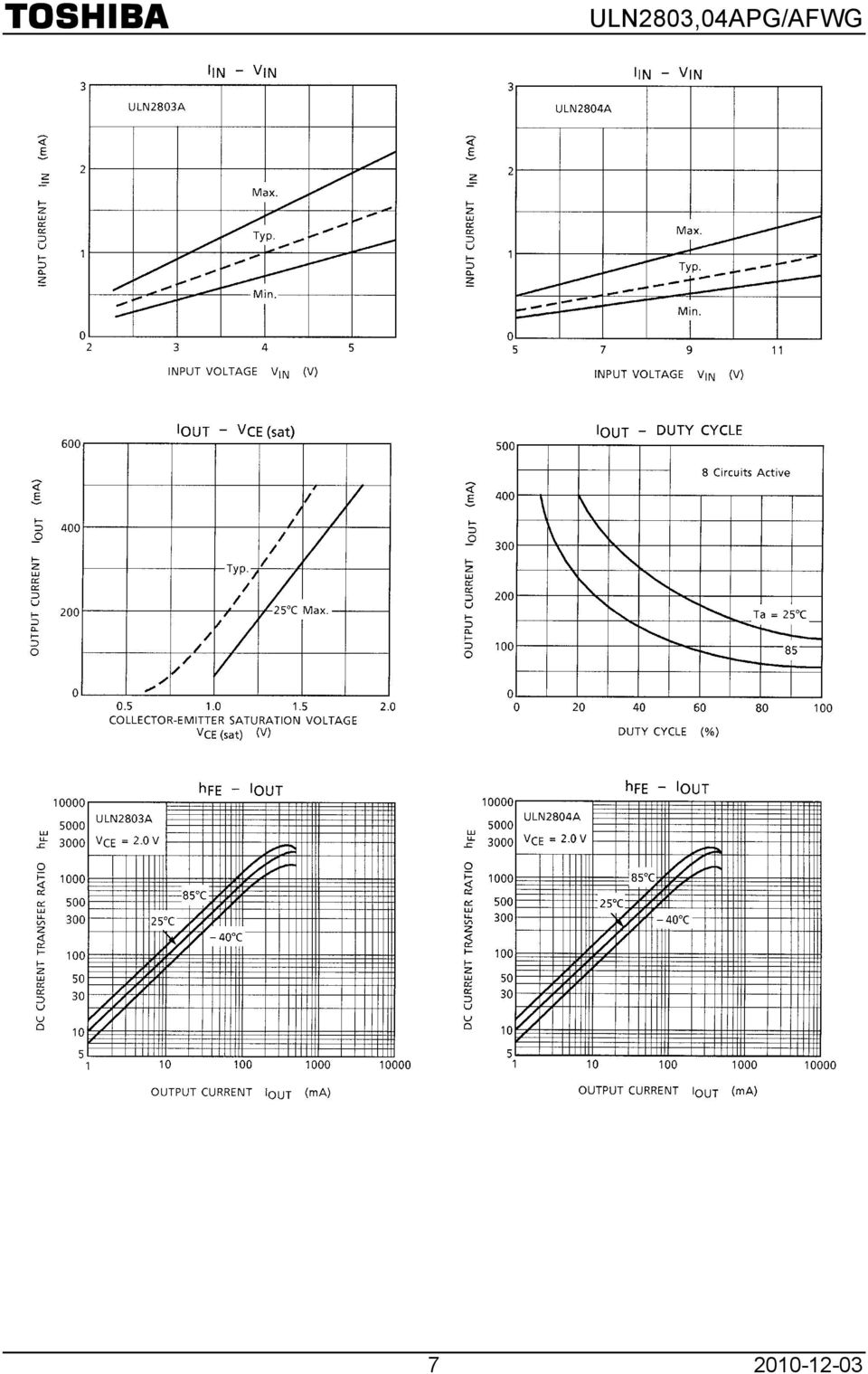
1 TOSHIBA Bipolar Digital Integrated Circuit Silicon Monolithic ULN2803,04APG/AFWG ULN2803APG,ULN2803AFWG,ULN2804APG,ULN2804AFWG (Manufactured by Toshiba Malaysia) 8ch Darlington Sink Driver The ULN2803APG / AFWG Series are high voltage, high current darlington drivers comprised of eight NPN darlington pairs. All units feature integral clamp diodes for switching inductive loads. Applications include relay, hammer, lamp and display (LED) drivers. ULN2803APG ULN2804APG Features Output current (single output) 500 ma (max) High sustaining voltage output 50 V (min) Output clamp diodes Inputs compatible with various types of logic. Package Type APG : DIP 18pin Package Type AFWG : SOL 18pin ULN2803AFWG ULN2804AFWG Weight DIP18 P F : g (Typ.) SOL18 P : 0.48 g (Typ.) Pin Connection (top view) Type Input Base Resistor Designation ULN2803APG / AFWG 2.7 kω TTL, 5 V CMOS ULN2804APG / AFWG 10.5 kω 6~15 V PMOS, CMOS 1
 500 ma (max) High sustaining voltage output 50 V (min) Output clamp diodes Inputs compatible with various types of logic.")
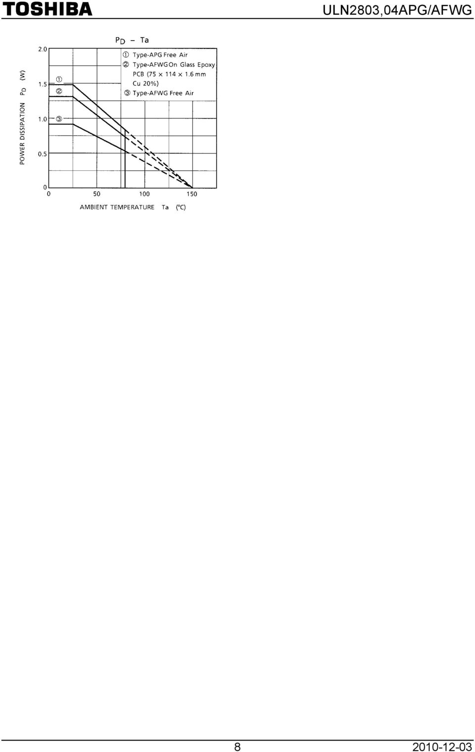
2 Schematics (each driver) ULN2803APG / AFWG ULN2804APG / AFWG Note: The input and output parasitic diodes cannot be used as clamp diodes. Absolute Maximum Ratings (Ta = 25 C) Characteristic Symbol Rating Unit Output sustaining voltage V CE (SUS) 0.5 to 50 V Output current I OUT 500 ma / ch Input voltage V IN 0.5 to 30 V Clamp diode reverse voltage V R 50 V Clamp diode forward current I F 500 ma Power dissipation APG P D 1.47 W AFWG 0.92 / 1.31 (Note) Operating temperature T opr 40 to 85 C Storage temperature T stg 55 to 150 C Note: On Glass Epoxy PCB ( mm Cu 20%) 2

3 Recommended Operating Conditions (Ta = 40~85 C) Characteristic Symbol Test Condition Min Typ. Max Unit Output sustaining voltage V CE (SUS) 0 50 V Output current APG AFWG I OUT t pw = 25 ms, Duty = 10%, 8 Circuits t pw = 25 ms, Duty = 50%, 8 Circuits t pw = 25 ms, Duty = 10%, 8 Circuits t pw = 25 ms, Duty = 50%, 8 Circuits ma / ch Input voltage V IN 0 30 V Input voltage (Output on) ULN2803A V IN (ON) ULN2804A 8 30 Clamp diode reverse voltage V R 50 V Clamp diode forward current I F 400 ma Power dissipation APG Ta = 85 C 0.76 P D AFWG Ta = 85 C (Note) 0.48 Note: On Glass Epoxy PCB ( mm Cu 20%) V W 3
 3.5 30 ULN2804A 8 30 Clamp diode reverse voltage V R 50 V Clamp diode forward current I F 400 ma Power dissipation APG Ta = 85 C 0.")
4 Electrical Characteristics (Ta = 25 C) Characteristic Output leakage current ULN2804A Symbol Test Cir Cuit I CEX 1 Test Condition Min Typ. Max Unit V CE = 50 V Ta = 25 C 50 V CE = 50 V Ta = 85 C 100 μa V CE = 50 V V IN = 1 V 500 I OUT = 350 ma, I IN = 500 μa Collector emitter saturation voltage VCE (sat) 2 I OUT = 200 ma, I IN = 350 μa I OUT = 100 ma, I IN = 250 μa V ULN2803A V IN = 3.85 V Input current ULN2804A I IN (ON) 2 V IN = 5 V V IN = 12 V ma I IN (OFF) 4 I OUT = 500 μa, Ta = 85 C μa V CE = 2 V, I OUT = 200 ma 2.4 ULN2803A V CE = 2 V, I OUT = 250 ma 2.7 Input voltage (Output on) ULN2804A V IN (ON) 5 V CE = 2 V, I OUT = 300 ma 3.0 V CE = 2 V, I OUT = 125 ma 5.0 V CE = 2 V, I OUT = 200 ma 6.0 V CE = 2 V, I OUT = 275 ma 7.0 V V CE = 2 V, I OUT = 350 ma 8.0 DC current transfer ratio h FE 2 V CE = 2 V, I OUT = 350 ma 1000 Clamp diode reverse current I R 6 Ta = 25 C (Note) 50 Ta = 85 C (Note) 100 μa Clamp diode forward voltage V F 7 I F = 350 ma 2.0 V Input capacitance C IN 15 pf Turn on delay t ON 8 R L = 125 Ω, V OUT = 50 V 0.1 Turn off delay t OFF R L = 125 Ω, V OUT = 50 V 0.2 μs Note: V R = V R (max) 4
 2 V IN = 5 V 0.35 0.5 V IN = 12 V 1.0 1.45 ma I IN (OFF) 4 I OUT = 500 μa, Ta = 85 C 50 65 μa V CE = 2 V, I OUT = 200 ma 2.4 ULN2803A V CE = 2 V, I OUT = 250 ma 2.")
5 Test Circuit 1. I CEX 2. V CE (sat), h FE 3. I IN (ON) 4. I IN (OFF) 5. V IN (ON) 6. I R 7. V F 5
 5.")
6 8. t ON, t OFF Note 1: Pulse Width 50 μs, Duty Cycle 10% Output Impedance 50 Ω, t r 5 ns, t f 10 ns Note 2: See below. Input Condition Type Number R1 V IH ULN2803A 0Ω 3 V ULN2804A 0Ω 8 V Note 3: C L includes probe and jig capacitance Precautions for Using This IC does not integrate protection circuits such as overcurrent and overvoltage protectors. Thus, if excess current or voltage is applied to the IC, the IC may be damaged. Please design the IC so that excess current or voltage will not be applied to the IC. Utmost care is necessary in the design of the output line, COMMON and GND line since IC may be destroyed due to short circuit between outputs, air contamination fault, or fault by improper grounding. 6

7 7
8 8
9 Package Dimensions DIP18 P F Unit: mm Weight: g (Typ.) 9

10 Package Dimensions SOL18 P Unit: mm Weight: 0.48 g (Typ.) 10

11 Notes on Contents 1. Equivalent Circuits The equivalent circuit diagrams may be simplified or some parts of them may be omitted for explanatory purposes. 2. Test Circuits Components in the test circuits are used only to obtain and confirm the device characteristics. These components and circuits are not guaranteed to prevent malfunction or failure from occurring in the application equipment. IC Usage Considerations Notes on Handling of ICs (1) The absolute maximum ratings of a semiconductor device are a set of ratings that must not be exceeded, even for a moment. Do not exceed any of these ratings. Exceeding the rating(s) may cause the device breakdown, damage or deterioration, and may result injury by explosion or combustion. (2) Use an appropriate power supply fuse to ensure that a large current does not continuously flow in case of over current and/or IC failure. The IC will fully break down when used under conditions that exceed its absolute maximum ratings, when the wiring is routed improperly or when an abnormal pulse noise occurs from the wiring or load, causing a large current to continuously flow and the breakdown can lead smoke or ignition. To minimize the effects of the flow of a large current in case of breakdown, appropriate settings, such as fuse capacity, fusing time and insertion circuit location, are required. (3) If your design includes an inductive load such as a motor coil, incorporate a protection circuit into the design to prevent device malfunction or breakdown caused by the current resulting from the inrush current at power ON or the negative current resulting from the back electromotive force at power OFF. IC breakdown may cause injury, smoke or ignition. Use a stable power supply with ICs with built-in protection functions. If the power supply is unstable, the protection function may not operate, causing IC breakdown. IC breakdown may cause injury, smoke or ignition. (4) Do not insert devices in the wrong orientation or incorrectly. Make sure that the positive and negative terminals of power supplies are connected properly. Otherwise, the current or power consumption may exceed the absolute maximum rating, and exceeding the rating(s) may cause the device breakdown, damage or deterioration, and may result injury by explosion or combustion. In addition, do not use any device that is applied the current with inserting in the wrong orientation or incorrectly even just one time. (5) Carefully select external components (such as inputs and negative feedback capacitors) and load components (such as speakers), for example, power amp and regulator. If there is a large amount of leakage current such as input or negative feedback condenser, the IC output DC voltage will increase. If this output voltage is connected to a speaker with low input withstand voltage, overcurrent or IC failure can cause smoke or ignition. (The over current can cause smoke or ignition from the IC itself.) In particular, please pay attention when using a Bridge Tied Load (BTL) connection type IC that inputs output DC voltage to a speaker directly. 11
 The absolute maximum ratings of a semiconductor device are a set of ratings that must not be exceeded, even for a moment.")
12 Points to Remember on Handling of ICs ULN2803,04APG/AFWG (1) Heat Radiation Design In using an IC with large current flow such as power amp, regulator or driver, please design the device so that heat is appropriately radiated, not to exceed the specified junction temperature (Tj) at any time and condition. These ICs generate heat even during normal use. An inadequate IC heat radiation design can lead to decrease in IC life, deterioration of IC characteristics or IC breakdown. In addition, please design the device taking into considerate the effect of IC heat radiation with peripheral components. (2) Back-EMF When a motor rotates in the reverse direction, stops or slows down abruptly, a current flow back to the motor s power supply due to the effect of back-emf. If the current sink capability of the power supply is small, the device s motor power supply and output pins might be exposed to conditions beyond absolute maximum ratings. To avoid this problem, take the effect of back-emf into consideration in system design. About solderability, following conditions were confirmed Solderability (1) Use of Sn-37Pb solder Bath solder bath temperature = 230 C dipping time = 5 seconds the number of times = once use of R-type flux (2) Use of Sn-3.0Ag-0.5Cu solder Bath solder bath temperature = 245 C dipping time = 5 seconds the number of times = once use of R-type flux 12

13 RESTRICTIONS ON PRODUCT USE Toshiba Corporation, and its subsidiaries and affiliates (collectively TOSHIBA ), reserve the right to make changes to the information in this document, and related hardware, software and systems (collectively Product ) without notice. This document and any information herein may not be reproduced without prior written permission from TOSHIBA. Even with TOSHIBA s written permission, reproduction is permissible only if reproduction is without alteration/omission. Though TOSHIBA works continually to improve Product s quality and reliability, Product can malfunction or fail. Customers are responsible for complying with safety standards and for providing adequate designs and safeguards for their hardware, software and systems which minimize risk and avoid situations in which a malfunction or failure of Product could cause loss of human life, bodily injury or damage to property, including data loss or corruption. Before customers use the Product, create designs including the Product, or incorporate the Product into their own applications, customers must also refer to and comply with (a) the latest versions of all relevant TOSHIBA information, including without limitation, this document, the specifications, the data sheets and application notes for Product and the precautions and conditions set forth in the TOSHIBA Semiconductor Reliability Handbook and (b) the instructions for the application with which the Product will be used with or for. Customers are solely responsible for all aspects of their own product design or applications, including but not limited to (a) determining the appropriateness of the use of this Product in such design or applications; (b) evaluating and determining the applicability of any information contained in this document, or in charts, diagrams, programs, algorithms, sample application circuits, or any other referenced documents; and (c) validating all operating parameters for such designs and applications. TOSHIBA ASSUMES NO LIABILITY FOR CUSTOMERS PRODUCT DESIGN OR APPLICATIONS. Product is intended for use in general electronics applications (e.g., computers, personal equipment, office equipment, measuring equipment, industrial robots and home electronics appliances) or for specific applications as expressly stated in this document. Product is neither intended nor warranted for use in equipment or systems that require extraordinarily high levels of quality and/or reliability and/or a malfunction or failure of which may cause loss of human life, bodily injury, serious property damage or serious public impact ( Unintended Use ). Unintended Use includes, without limitation, equipment used in nuclear facilities, equipment used in the aerospace industry, medical equipment, equipment used for automobiles, trains, ships and other transportation, traffic signaling equipment, equipment used to control combustions or explosions, safety devices, elevators and escalators, devices related to electric power, and equipment used in finance-related fields. Do not use Product for Unintended Use unless specifically permitted in this document. Do not disassemble, analyze, reverse-engineer, alter, modify, translate or copy Product, whether in whole or in part. Product shall not be used for or incorporated into any products or systems whose manufacture, use, or sale is prohibited under any applicable laws or regulations. The information contained herein is presented only as guidance for Product use. No responsibility is assumed by TOSHIBA for any infringement of patents or any other intellectual property rights of third parties that may result from the use of Product. No license to any intellectual property right is granted by this document, whether express or implied, by estoppel or otherwise. ABSENT A WRITTEN SIGNED AGREEMENT, EXCEPT AS PROVIDED IN THE RELEVANT TERMS AND CONDITIONS OF SALE FOR PRODUCT, AND TO THE MAXIMUM EXTENT ALLOWABLE BY LAW, TOSHIBA (1) ASSUMES NO LIABILITY WHATSOEVER, INCLUDING WITHOUT LIMITATION, INDIRECT, CONSEQUENTIAL, SPECIAL, OR INCIDENTAL DAMAGES OR LOSS, INCLUDING WITHOUT LIMITATION, LOSS OF PROFITS, LOSS OF OPPORTUNITIES, BUSINESS INTERRUPTION AND LOSS OF DATA, AND (2) DISCLAIMS ANY AND ALL EXPRESS OR IMPLIED WARRANTIES AND CONDITIONS RELATED TO SALE, USE OF PRODUCT, OR INFORMATION, INCLUDING WARRANTIES OR CONDITIONS OF MERCHANTABILITY, FITNESS FOR A PARTICULAR PURPOSE, ACCURACY OF INFORMATION, OR NONINFRINGEMENT. Do not use or otherwise make available Product or related software or technology for any military purposes, including without limitation, for the design, development, use, stockpiling or manufacturing of nuclear, chemical, or biological weapons or missile technology products (mass destruction weapons). Product and related software and technology may be controlled under the Japanese Foreign Exchange and Foreign Trade Law and the U.S. Export Administration Regulations. Export and re-export of Product or related software or technology are strictly prohibited except in compliance with all applicable export laws and regulations. Please contact your TOSHIBA sales representative for details as to environmental matters such as the RoHS compatibility of Product. Please use Product in compliance with all applicable laws and regulations that regulate the inclusion or use of controlled substances, including without limitation, the EU RoHS Directive. TOSHIBA assumes no liability for damages or losses occurring as a result of noncompliance with applicable laws and regulations. 13

TD62783APG,TD62783AFG
 TOSHIBA Bipolar Digital Integrated Circuit Silicon Monolithic TD62783APG,TD62783AFG TD62783APG/AFG 8 ch High-Voltage Source Driver The TD62783APG/AFG Series are comprised of eight source current Transistor
TBD62083APG, TBD62083AFG, TBD62083AFNG, TBD62083AFWG TBD62084APG, TBD62084AFG, TBD62084AFNG, TBD62084AFWG
 TBD62083A, TBD62084A TOSHIBA BiCD Integrated Circuit Silicon Monolithic TBD62083APG, TBD62083AFG, TBD62083AFNG, TBD62083AFWG TBD62084APG, TBD62084AFG, TBD62084AFNG, TBD62084AFWG 8channel sink type DMOS
TOSHIBA Transistor Silicon NPN Epitaxial Type (PCT Process) 2SC2383
 2SC2383") TOSHIBA Transistor Silicon NPN Epitaxial Type (PCT Process) SC8 Color TV Vertical Deflection Output Applications Color TV Class-B Sound Output Applications Unit: mm High breakdown voltage: V CEO = 6 V
TOSHIBA Transistor Silicon NPN Epitaxial Type (PCT Process) SC8 Color TV Vertical Deflection Output Applications Color TV Class-B Sound Output Applications Unit: mm High breakdown voltage: V CEO = 6 V
TOSHIBA Transistor Silicon PNP Epitaxial Type (PCT Process) 2SA1020
 2SA1020") 2SA12 TOSHIBA Transistor Silicon PNP Epitaxial Type (PCT Process) 2SA12 Power Amplifier Applications Power Switching Applications Unit: mm Low Collector saturation voltage: V CE (sat) =.5 V (max) (I C
2SA12 TOSHIBA Transistor Silicon PNP Epitaxial Type (PCT Process) 2SA12 Power Amplifier Applications Power Switching Applications Unit: mm Low Collector saturation voltage: V CE (sat) =.5 V (max) (I C
SSM3K335R SSM3K335R. 1. Applications. 2. Features. 3. Packaging and Pin Configuration. 2012-07-19 Rev.3.0. Silicon N-Channel MOS (U-MOS -H)
") MOSFETs Silicon N-Channel MOS (U-MOS-H) SSM3K335R SSM3K335R 1. Applications Power Management Switches DC-DC Converters 2. Features (1) 4.5-V gate drive voltage. (2) Low drain-source on-resistance : R DS(ON)
MOSFETs Silicon N-Channel MOS (U-MOS-H) SSM3K335R SSM3K335R 1. Applications Power Management Switches DC-DC Converters 2. Features (1) 4.5-V gate drive voltage. (2) Low drain-source on-resistance : R DS(ON)
TOSHIBA Bipolar Linear Integrated Circuit Silicon Monolithic TAR5SB15~TAR5SB50
 TOSHIBA Bipolar Linear Integrated Circuit Silicon Monolithic TARSB~TARSB Point Regulators (Low-Dropout Regulator) TARSB~TARSB The TARSBxx Series is comprised of general-purpose bipolar single-power-supply
TPN4R712MD TPN4R712MD. 1. Applications. 2. Features. 3. Packaging and Internal Circuit. 2014-12 2015-04-21 Rev.4.0. Silicon P-Channel MOS (U-MOS )
") MOSFETs Silicon P-Channel MOS (U-MOS) TPN4R712MD TPN4R712MD 1. Applications Lithium-Ion Secondary Batteries Power Management Switches 2. Features (1) Low drain-source on-resistance: R DS(ON) = 3.8 mω (typ.)
MOSFETs Silicon P-Channel MOS (U-MOS) TPN4R712MD TPN4R712MD 1. Applications Lithium-Ion Secondary Batteries Power Management Switches 2. Features (1) Low drain-source on-resistance: R DS(ON) = 3.8 mω (typ.)
TOSHIBA BiCD Integrated Circuit Silicon Monolithic
 TOSHIBA BiCD Integrated Circuit Silicon Monolithic PWM Chopper-Type bipolar Stepg Motor Driver IC The is a PWM chopper-type single-chip bipolar sinusoidal micro-step stepg motor driver. Forward and reverse
Digital-Output Magnetic Sensor (Hall IC)
") TOSHIBA Semiconductor Application Note Digital-Output Magnetic Sensor (Hall IC) 1. Introduction The digital-output magnetic sensor is essentially a sensor which detects the magnetic flux density of a magnet
TOSHIBA Semiconductor Application Note Digital-Output Magnetic Sensor (Hall IC) 1. Introduction The digital-output magnetic sensor is essentially a sensor which detects the magnetic flux density of a magnet
HG2 Series Product Brief
 Solid State Drives Product Brief - 1 - Rev.2 1. SCOPE T his document describes the specifications of the following model 1.1 2.5inch Case Type Product Number THNS064GG2BB THNS128GG4BB THNS256GG8BB THNS512GG8BB
T B 6 6 1 2 F N G TB6612FNG. Driver IC for Dual DC motor. Features 2007-06-30. Toshiba Bi-CD Integrated Circuit Silicon Monolithic
 Driver IC for Dual DC motor Toshiba Bi-CD Integrated Circuit Silicon Monolithic T B 6 6 1 2 F N G TB6612FNG is a driver IC for DC motor with output transistor in LD MOS structure with low ON-resistor.
Part Number Decoder for Toshiba NAND Flash
 Part Number Decoder for Toshiba NAND Flash Revision 1.3 Memory Application Engineering Dept. Memory Division, TOSHIBA CORPORATION Semiconductor Company Sep.24 th 2010 Copyright 2006, Toshiba Corporation.
ULN2001, ULN2002 ULN2003, ULN2004
 ULN2001, ULN2002 ULN2003, ULN2004 Seven Darlington array Datasheet production data Features Seven Darlingtons per package Output current 500 ma per driver (600 ma peak) Output voltage 50 V Integrated suppression
TLP504A,TLP504A 2. Programmable Controllers AC / DC Input Module Solid State Relay. Pin Configurations (top view) 2002-09-25
 2002-09-25") TOSHIBA Photocoupler GaAs Ired & Photo Transistor TLP4A,TLP4A 2 TLP4A,TLP4A 2 Programmable Controllers AC / DC Input Module Solid State Relay Unit in mm The TOSHIBA TLP4A and TLP4A 2 consists of a photo
TOSHIBA Photocoupler GaAs Ired & Photo Transistor TLP4A,TLP4A 2 TLP4A,TLP4A 2 Programmable Controllers AC / DC Input Module Solid State Relay Unit in mm The TOSHIBA TLP4A and TLP4A 2 consists of a photo
UTC UNISONIC TECHNOLOGIES CO. LTD 1 LINEAR INTEGRATED CIRCUIT 7CH DARLINGTON SINK DRIVER
 kω UTC ULN 7CH DARLINGTON SINK DRIVER DESCRIPTION The UTC ULN is high-voltage, high-current darlington drivers comprised of seven NPN darlingto pairs. All units feature integral clamp diodes for switching
TLP185 TLP185. Office Machine Programmable Controllers AC Adapter I/O Interface Board. Pin Configuration(top view) 2012-02-14
 2012-02-14") TOSHIBA Photocoupler GaAs Ired & Photo Transistor TLP85 Office Machine Programmable Controllers AC Adapter I/O Interface Board Unit: mm The TOSHIBA mini flat coupler TLP85 is a small outline coupler, suitable
TOSHIBA Photocoupler GaAs Ired & Photo Transistor TLP85 Office Machine Programmable Controllers AC Adapter I/O Interface Board Unit: mm The TOSHIBA mini flat coupler TLP85 is a small outline coupler, suitable
TOSHIBA Insulated Gate Bipolar Transistor Silicon N Channel IGBT GT60J323
 GT6J2 TOSHIBA Insulated Gate Bipolar Transistor Silicon N Channel IGBT GT6J2 Current Resonance Inverter Switching Application Unit: mm Enhancement mode type High speed : t f =.6 μs (typ.) (I C = 6A) Low
TLP281,TLP281-4 TLP281,TLP281-4 PROGRAMMABLE CONTROLLERS AC/DC-INPUT MODULE PC CARD MODEM(PCMCIA) Pin Configuration (top view) 2007-10-01
 Pin Configuration (top view) 2007-10-01") TOSHIBA PHOTOCOUPLER GaAs IRED & PHOTO-TRANSISTOR,-4,-4 PROGRAMMABLE CONTROLLERS AC/DC-INPUT MODULE PC CARD MODEM(PCMCIA) Unit in mm and -4 is a very small and thin coupler, suitable for surface mount
TOSHIBA PHOTOCOUPLER GaAs IRED & PHOTO-TRANSISTOR,-4,-4 PROGRAMMABLE CONTROLLERS AC/DC-INPUT MODULE PC CARD MODEM(PCMCIA) Unit in mm and -4 is a very small and thin coupler, suitable for surface mount
ULN2801A, ULN2802A, ULN2803A, ULN2804A
 ULN2801A, ULN2802A, ULN2803A, ULN2804A Eight Darlington array Datasheet production data Features Eight Darlington transistors with common emitters Output current to 500 ma Output voltage to 50 V Integral
TLP521 1,TLP521 2,TLP521 4
 TLP2,TLP2 2,TLP2 4 TOSHIBA Photocoupler GaAs Ired & Photo Transistor TLP2,TLP2 2,TLP2 4 Programmable Controllers AC/DC Input Module Solid State Relay Unit in mm The TOSHIBA TLP2, 2 and 4 consist of a photo
EM3242. Angle Sensor IC [EM3242]
![EM3242. Angle Sensor IC [EM3242]](/thumbs/26/7602427.jpg "EM3242. Angle Sensor IC [EM3242]") EM3242 Angle Sensor IC Applications Small absolute rotary encoder Small input device (mode selector, volume control, and soon) Potentiometer Rotary switch Features Si monolithic rotary position sensor
EM3242 Angle Sensor IC Applications Small absolute rotary encoder Small input device (mode selector, volume control, and soon) Potentiometer Rotary switch Features Si monolithic rotary position sensor
S-57M1 Series HIGH-SPEED BIPOLAR HALL EFFECT LATCH. Features. Applications. Package. www.sii-ic.com
 www.sii-ic.com HIGH-SPEED BIPOLAR HALL EFFECT LATCH SII Semiconductor Corporation, 2011-2013 Rev.1.2_01 The, developed by CMOS technology, is a high-accuracy Hall IC that operates with a high-sensitivity,
CLA4607-085LF: Surface Mount Limiter Diode
 DATA SHEET CLA4607-085LF: Surface Mount Limiter Diode Applications Low-loss, high-power limiters Receiver protectors Anode (Pin 1) Anode (Pin 3) Features Low thermal resistance: 55 C/W Typical threshold
Optocoupler, Phototransistor Output, with Base Connection
 4N25, 4N26, 4N27, 4N28 Optocoupler, Phototransistor Output, FEATURES A 6 B Isolation test voltage 5000 V RMS Interfaces with common logic families C 2 5 C Input-output coupling capacitance < pf NC 3 4
TB6600HG. HZIP25-P-1.00F Ron (upper + lower) = 0.4 Ω (typ.) Weight: Forward and reverse rotation control available
 = 0.4 Ω (typ.) Weight: Forward and reverse rotation control available") TOSHIBA BiCD Integrated Circuit Silicon Monolithic TB66HG PWM Chopper-Type bipolar Stepping Motor Driver IC The TB66HG is a PWM chopper-type single-chip bipolar sinusoidal micro-step stepping motor driver.
TOSHIBA BiCD Integrated Circuit Silicon Monolithic TB66HG PWM Chopper-Type bipolar Stepping Motor Driver IC The TB66HG is a PWM chopper-type single-chip bipolar sinusoidal micro-step stepping motor driver.
LB1836M. Specifications. Monolithic Digital IC Low-Saturation Bidirectional Motor Driver for Low-Voltage Drive. Absolute Maximum Ratings at Ta = 25 C
 Ordering number : EN397F LB136M Monolithic Digital IC Low-Saturation Bidirectional Motor Driver for Low-Voltage Drive http://onsemi.com Overview The LB136M is a low-saturation two-channel bidirectional
S-57P1 S Series FOR AUTOMOTIVE 150 C OPERATION HIGH-WITHSTAND VOLTAGE HIGH-SPEED BIPOLAR HALL EFFECT LATCH. Features. Applications.
 www.sii-ic.com FOR AUTOMOTIVE 150 C OPERATION HIGH-WITHSTAND VOLTAGE HIGH-SPEED BIPOLAR HALL EFFECT LATCH SII Semiconductor Corporation, 2015 The, developed by CMOS technology, is a high-accuracy Hall
L6234. Three phase motor driver. Features. Description
 Three phase motor driver Features Supply voltage from 7 to 52 V 5 A peak current R DSon 0.3 Ω typ. value at 25 C Cross conduction protection TTL compatible driver Operating frequency up to 150 khz Thermal
2N6056. NPN Darlington Silicon Power Transistor DARLINGTON 8 AMPERE SILICON POWER TRANSISTOR 80 VOLTS, 100 WATTS
 NPN Darlington Silicon Power Transistor The NPN Darlington silicon power transistor is designed for general purpose amplifier and low frequency switching applications. High DC Current Gain h FE = 3000
NPN wideband transistor in a SOT89 plastic package.
 SOT89 Rev. 05 21 March 2013 Product data sheet 1. Product profile 1.1 General description in a SOT89 plastic package. 1.2 Features and benefits High gain Gold metallization ensures excellent reliability
Vdc. Vdc. Adc. W W/ C T J, T stg 65 to + 200 C
 2N6284 (NPN); 2N6286, Preferred Device Darlington Complementary Silicon Power Transistors These packages are designed for general purpose amplifier and low frequency switching applications. Features High
TOSHIBA CCD LINEAR IMAGE SENSOR CCD(Charge Coupled Device) TCD1304AP
 TCD1304AP") TOSHIBA CCD LINEAR IMAGE SENSOR CCD(Charge Coupled Device) TCD1304AP TCD1304AP The TCD1304AP is a high sensitive and low dark current 3648 elements linear image sensor. The sensor can be used for POS scanner.
TOSHIBA CCD LINEAR IMAGE SENSOR CCD(Charge Coupled Device) TCD1304AP TCD1304AP The TCD1304AP is a high sensitive and low dark current 3648 elements linear image sensor. The sensor can be used for POS scanner.
DATA SHEET. BST50; BST51; BST52 NPN Darlington transistors DISCRETE SEMICONDUCTORS. Product specification Supersedes data of 2001 Feb 20.
 DISCRETE SEMICONDUCTORS DATA SHEET book, halfpage M3D109 Supersedes data of 2001 Feb 20 2004 Dec 09 FEATURES High current (max. 0.5 A) Low voltage (max. 80 V) Integrated diode and resistor. APPLICATIONS
74HC377; 74HCT377. 1. General description. 2. Features and benefits. 3. Ordering information
 Rev. 4 24 February 2016 Product data sheet 1. General description 2. Features and benefits 3. Ordering information The is an octal positive-edge triggered D-type flip-flop. The device features clock (CP)
Taping code. Reel size (mm) 2SCR513P MPT3 4540 T100 180 12 1,000 NC
 2SCR513P MPT3 4540 T100 180 12 1,000 NC") 2SCR53P NPN.0A 50 Middle Power Transistor Datasheet Outline Parameter alue MPT3 CEO 50 I C.0A Base Collector Emitter Features ) Suitable for Middle Power Driver 2) Complementary PNP Types : 2SAR53P 3)
2SCR53P NPN.0A 50 Middle Power Transistor Datasheet Outline Parameter alue MPT3 CEO 50 I C.0A Base Collector Emitter Features ) Suitable for Middle Power Driver 2) Complementary PNP Types : 2SAR53P 3)
HEF4011B. 1. General description. 2. Features and benefits. 3. Ordering information. 4. Functional diagram. Quad 2-input NAND gate
 Rev. 6 10 December 2015 Product data sheet 1. General description 2. Features and benefits 3. Ordering information The is a quad 2-input NAND gate. The outputs are fully buffered for the highest noise
Optocoupler, Phototransistor Output, with Base Connection
 Optocoupler, Phototransistor Output, with Base Connection FEATURES i794-4 DESCRIPTION This datasheet presents five families of Vishay industry standard single channel phototransistor couplers. These families
ULN2803A ULN2804A OCTAL PERIPHERAL DRIVER ARRAYS
 Order this document by ULN283/D The eight NPN Darlington connected transistors in this family of arrays are ideally suited for interfacing between low logic level digital circuitry (such as TTL, CMOS or
BD241A BD241C. NPN power transistors. Features. Applications. Description. NPN transistors. Audio, general purpose switching and amplifier transistors
 BD241A BD241C NPN power transistors Features. NPN transistors Applications Audio, general purpose switching and amplifier transistors Description The devices are manufactured in Planar technology with
74HC02; 74HCT02. 1. General description. 2. Features and benefits. Ordering information. Quad 2-input NOR gate
 Rev. 5 26 November 2015 Product data sheet 1. General description 2. Features and benefits The is a quad 2-input NOR gate. Inputs include clamp diodes. This enables the use of current limiting resistors
3-to-8 line decoder, demultiplexer with address latches
 Rev. 7 29 January 2016 Product data sheet 1. General description The is a high-speed Si-gate CMOS device and is pin compatible with low-power Schottky TTL (LSTTL). The is specified in compliance with JEDEC
8-bit binary counter with output register; 3-state
 Rev. 3 24 February 2016 Product data sheet 1. General description The is an 8-bit binary counter with a storage register and 3-state outputs. The storage register has parallel (Q0 to Q7) outputs. The binary
Optocoupler, Phototransistor Output, Dual Channel, SOIC-8 Package
 ILD25T, ILD26T, ILD27T, ILD211T, ILD213T Optocoupler, Phototransistor Output, Dual Channel, SOIC-8 Package i17925 A1 C2 A3 C4 i17918-2 8C 7E 6C 5E DESCRIPTION The ILD25T, ILD26T, ILD27T, ILD211T, and ILD213T
Quad 2-input NAND Schmitt trigger
 Rev. 9 15 December 2015 Product data sheet 1. General description 2. Features and benefits 3. Applications The is a quad two-input NAND gate. Each input has a Schmitt trigger circuit. The gate switches
1-of-4 decoder/demultiplexer
 Rev. 6 1 April 2016 Product data sheet 1. General description 2. Features and benefits 3. Applications The contains two 1-of-4 decoders/demultiplexers. Each has two address inputs (na0 and na1, an active
AP331A XX G - 7. Lead Free G : Green. Packaging (Note 2)
") Features General Description Wide supply Voltage range: 2.0V to 36V Single or dual supplies: ±1.0V to ±18V Very low supply current drain (0.4mA) independent of supply voltage Low input biasing current:
Features General Description Wide supply Voltage range: 2.0V to 36V Single or dual supplies: ±1.0V to ±18V Very low supply current drain (0.4mA) independent of supply voltage Low input biasing current:
74HC238; 74HCT238. 3-to-8 line decoder/demultiplexer
 Rev. 4 27 January 2016 Product data sheet 1. General description 2. Features and benefits 3. Ordering information The decodes three binary weighted address inputs (A0, A1 and A2) to eight mutually exclusive
Low forward voltage High breakdown voltage Guard-ring protected Hermetically sealed glass SMD package
 Rev. 6 10 September 2010 Product data sheet 1. Product profile 1.1 General description Planar with an integrated guard ring for stress protection, encapsulated in a small hermetically sealed glass SOD80C
DATA SHEET. PBSS5540Z 40 V low V CEsat PNP transistor DISCRETE SEMICONDUCTORS. Product data sheet Supersedes data of 2001 Jan 26. 2001 Sep 21.
 DISCRETE SEMICONDUCTORS DATA SHEET fpage M3D87 PBSS554Z 4 V low V CEsat PNP transistor Supersedes data of 21 Jan 26 21 Sep 21 FEATURES Low collector-emitter saturation voltage High current capability Improved
INTEGRATED CIRCUITS. 74LVC08A Quad 2-input AND gate. Product specification IC24 Data Handbook. 1997 Jun 30
 INTEGRATED CIRCUITS IC24 Data Handbook 1997 Jun 30 FEATURES Wide supply voltage range of 1.2 V to 3.6 V In accordance with JEDEC standard no. 8-1A Inputs accept voltages up to 5.5 V CMOS low power consumption
The 74LVC1G11 provides a single 3-input AND gate.
 Rev. 8 17 September 2015 Product data sheet 1. General description The provides a single 3-input AND gate. The input can be driven from either 3.3 V or 5 V devices. This feature allows the use of this
BIPOLAR ANALOG INTEGRATED CIRCUIT
 DATA SHEET BIPOLAR ANALOG INTEGRATED CIRCUIT μpc8tk SiGe:C LOW NOISE AMPLIFIER FOR GPS/MOBILE COMMUNICATIONS DESCRIPTION The μpc8tk is a silicon germanium carbon (SiGe:C) monolithic integrated circuit
TS555. Low-power single CMOS timer. Description. Features. The TS555 is a single CMOS timer with very low consumption:
 Low-power single CMOS timer Description Datasheet - production data The TS555 is a single CMOS timer with very low consumption: Features SO8 (plastic micropackage) Pin connections (top view) (I cc(typ)
HEF4021B. 1. General description. 2. Features and benefits. 3. Ordering information. 8-bit static shift register
 Rev. 10 21 March 2016 Product data sheet 1. General description 2. Features and benefits 3. Ordering information The is an (parallel-to-serial converter) with a synchronous serial data input (DS), a clock
2N6387, 2N6388. Plastic Medium-Power Silicon Transistors DARLINGTON NPN SILICON POWER TRANSISTORS 8 AND 10 AMPERES 65 WATTS, 60-80 VOLTS
 2N6388 is a Preferred Device Plastic MediumPower Silicon Transistors These devices are designed for generalpurpose amplifier and lowspeed switching applications. Features High DC Current Gain h FE = 2500
74HC107; 74HCT107. Dual JK flip-flop with reset; negative-edge trigger
 Rev. 5 30 November 2015 Product data sheet 1. General description 2. Features and benefits 3. Ordering information The is a dual negative edge triggered JK flip-flop featuring individual J and K inputs,
SMS7630-061: Surface Mount, 0201 Zero Bias Silicon Schottky Detector Diode
 DATA SHEET SMS7630-061: Surface Mount, 0201 Zero Bias Silicon Schottky Detector Diode Applications Sensitive RF and microwave detector circuits Sampling and mixer circuits High volume wireless systems
Optocoupler, Phototransistor Output, with Base Connection
 HA/HA2/HA3/HA4/HA5 FEATURES Interfaces with common logic families Input-output coupling capacitance < pf Industry standard dual-in line 6-pin package A C NC 2 3 6 5 4 B C E Isolation test voltage: 5300
74HC175; 74HCT175. Quad D-type flip-flop with reset; positive-edge trigger
 Rev. 5 29 January 2016 Product data sheet 1. General description 2. Features and benefits 3. Ordering information The is a quad positive-edge triggered D-type flip-flop with individual data inputs (Dn)
40 V, 200 ma NPN switching transistor
 Rev. 01 21 July 2009 Product data sheet BOTTOM VIEW 1. Product profile 1.1 General description NPN single switching transistor in a SOT883 (SC-101) leadless ultra small Surface-Mounted Device (SMD) plastic
74HC154; 74HCT154. 4-to-16 line decoder/demultiplexer
 Rev. 7 29 February 2016 Product data sheet 1. General description 2. Features and benefits 3. Ordering information The is a. It decodes four binary weighted address inputs (A0 to A3) to sixteen mutually
10 ma LED driver in SOT457
 SOT457 in SOT457 Rev. 1 20 February 2014 Product data sheet 1. Product profile 1.1 General description LED driver consisting of resistor-equipped PNP transistor with two diodes on one chip in an SOT457
BIPOLAR ANALOG INTEGRATED CIRCUIT
 DATA SHEET BIPOLAR ANALOG INTEGRATED CIRCUIT μpc823tu SiGe:C LOW NOISE AMPLIFIER FOR GPS DESCRIPTION The μpc823tu is a silicon germanium carbon (SiGe:C) monolithic integrated circuit designed as low noise
2STBN15D100. Low voltage NPN power Darlington transistor. Features. Application. Description
 Low voltage NPN power Darlington transistor Features Good h FE linearity High f T frequency Monolithic Darlington configuration with integrated antiparallel collector-emitter diode TAB Application Linear
DATA SHEET. MMBT3904 NPN switching transistor DISCRETE SEMICONDUCTORS. Product data sheet Supersedes data of 2002 Oct 04. 2004 Feb 03.
 DISCRETE SEMICONDUCTORS DATA SHEET dbook, halfpage M3D088 Supersedes data of 2002 Oct 04 2004 Feb 03 FEATURES Collector current capability I C = 200 ma Collector-emitter voltage V CEO = 40 V. APPLICATIONS
Planar PIN diode in a SOD323 very small plastic SMD package.
 Rev. 8 12 May 2015 Product data sheet 1. Product profile 1.1 General description Planar PIN diode in a SOD323 very small plastic SMD package. 1.2 Features and benefits High voltage, current controlled
Description. Table 1. Device summary. Order code Temperature range Package Packaging Marking
 14-stage ripple carry binary counter/divider and oscillator Applications Automotive Industrial Computer Consumer Description Datasheet - production data Features Medium speed operation Common reset Fully
DISCRETE SEMICONDUCTORS DATA SHEET BC856; BC857; BC858
 DISCRETE SEMICONDUCTORS DATA SHEET Supersedes data of 23 Apr 9 24 Jan 16 FEATURES Low current (max. 1 ma) Low voltage (max. 65 V). APPLICATIONS General purpose switching and amplification. PINNING PIN
MIC4451/4452. General Description. Features. Applications. Functional Diagram V S. 12A-Peak Low-Side MOSFET Driver. Bipolar/CMOS/DMOS Process
 12A-Peak Low-Side MOSFET Driver Bipolar/CMOS/DMOS Process General Description MIC4451 and MIC4452 CMOS MOSFET drivers are robust, efficient, and easy to use. The MIC4451 is an inverting driver, while the
SPI-8001TW. Switching Regulators. Dual 1.5 A, DC/DC Step-Down Converter. SANKEN ELECTRIC CO., LTD. http://www.sanken-ele.co.jp/en/
 Data Sheet 27469.301.1 Designed to meet high-current requirements at high efficiency in industrial and consumer applications; embedded core, memory, or logic supplies; TVs, VCRs, and office equipment,
74HCU04. 1. General description. 2. Features and benefits. 3. Ordering information. Hex unbuffered inverter
 Rev. 7 8 December 2015 Product data sheet 1. General description The is a hex unbuffered inverter. Inputs include clamp diodes. This enables the use of current limiting resistors to interface inputs to
N-channel enhancement mode TrenchMOS transistor
 FEATURES SYMBOL QUICK REFERENCE DATA Trench technology d V DSS = V Low on-state resistance Fast switching I D = A High thermal cycling performance Low thermal resistance R DS(ON) mω (V GS = V) g s R DS(ON)
74HC165; 74HCT165. 8-bit parallel-in/serial out shift register
 Rev. 4 28 December 2015 Product data sheet 1. General description 2. Features and benefits 3. Applications 4. Ordering information The is an 8-bit serial or parallel-in/serial-out shift register. The device
4-bit binary full adder with fast carry CIN + (A1 + B1) + 2(A2 + B2) + 4(A3 + B3) + 8(A4 + B4) = = S1 + 2S2 + 4S3 + 8S4 + 16COUT
 + 2(A2 + B2) + 4(A3 + B3) + 8(A4 + B4) = = S1 + 2S2 + 4S3 + 8S4 + 16COUT") Rev. 03 11 November 2004 Product data sheet 1. General description 2. Features The is a high-speed Si-gate CMOS device and is pin compatible with low power Schottky TTL (LSTTL). The is specified in compliance
Rev. 03 11 November 2004 Product data sheet 1. General description 2. Features The is a high-speed Si-gate CMOS device and is pin compatible with low power Schottky TTL (LSTTL). The is specified in compliance
TOSHIBA CCD Image Sensor CCD (charge coupled device) TCD2955D
 TCD2955D") Preliminary TOSHIBA CCD Image Sensor CCD (charge coupled device) TCD2955D The TCD2955D is a high sensitive and low dark current 4240 elements 6 line CCD color image sensor which includes CCD drive circuit
Preliminary TOSHIBA CCD Image Sensor CCD (charge coupled device) TCD2955D The TCD2955D is a high sensitive and low dark current 4240 elements 6 line CCD color image sensor which includes CCD drive circuit
VN05N. High side smart power solid state relay PENTAWATT. Features. Description
 High side smart power solid state relay Features Type V DSS R DS(on) I OUT V CC VN05N 60 V 0.18 Ω 13 A 26 V Output current (continuous): 13A @ Tc=25 C 5V logic level compatible input Thermal shutdown Under
74HC138; 74HCT138. 3-to-8 line decoder/demultiplexer; inverting
 Rev. 6 28 December 2015 Product data sheet 1. General description 2. Features and benefits 3. Ordering information The decodes three binary weighted address inputs (A0, A1 and A2) to eight mutually exclusive
CLA Series: Silicon Limiter Diode Bondable Chips
 DATA SHEET CLA Series: Silicon Limiter Diode Bondable Chips Applications LNA receiver protection Commercial and defense radar Features Established Skyworks limiter diode process High-power, mid-range,
74HC4040; 74HCT4040. 12-stage binary ripple counter
 Rev. 5 3 February 2016 Product data sheet 1. General description 2. Features and benefits 3. Applications 4. Ordering information The is a with a clock input (CP), an overriding asynchronous master reset
GP2Y0D810Z0F. Distance Measuring Sensor Unit Digital output (100 mm) type GP2Y0D810Z0F
 type GP2Y0D810Z0F") GP2Y0D810Z0F Distance Measuring Sensor Unit Digital output (100 mm) type Description GP2Y0D810Z0F is distance measuring sensor unit, composed of an integrated combination of PD (photo diode), IRED (infrared
GP2Y0D810Z0F Distance Measuring Sensor Unit Digital output (100 mm) type Description GP2Y0D810Z0F is distance measuring sensor unit, composed of an integrated combination of PD (photo diode), IRED (infrared
L6219. Stepper motor driver. Features. Description
 Stepper motor driver Features Able to drive both windings of bipolar stepper motor Output current up to 750 ma each winding Wide voltage range: 10 V to 46 V Half-step, full-step and microstepping mode
INTEGRATED CIRCUITS. NE558 Quad timer. Product data Supersedes data of 2001 Aug 03. 2003 Feb 14
 INTEGRATED CIRCUITS Supersedes data of 2001 Aug 03 2003 Feb 14 DESCRIPTION The Quad Timers are monolithic timing devices which can be used to produce four independent timing functions. The output sinks
Old Company Name in Catalogs and Other Documents
 To our customers, Old Company Name in Catalogs and Other Documents On April st,, NEC Electronics Corporation merged with Renesas Technology Corporation, and Renesas Electronics Corporation took over all
BAT54 series SOT23 Schottky barrier diodes Rev. 5 5 October 2012 Product data sheet 1. Product profile 1.1 General description
 SOT2 Rev. 5 5 October 2012 Product data sheet 1. Product profile 1.1 General description Planar with an integrated guard ring for stress protection, encapsulated in a small SOT2 (TO-26AB) Surface-Mounted
S112-XHS. Description. Features. Agency Approvals. Applications. Absolute Maximum Ratings. Schematic Diagram. Ordering Information
 Description Features The S112-X is a bi-directional, single-pole, single-throw, normally open multipurpose solid-state relay. The circuit is composed of one input IR LED with a series limiting resistor
TIP140, TIP141, TIP142, (NPN); TIP145, TIP146, TIP147, (PNP) Darlington Complementary Silicon Power Transistors
; TIP145, TIP146, TIP147, (PNP) Darlington Complementary Silicon Power Transistors") TIP140, TIP141, TIP142, (); TIP145, TIP146, TIP147, () Darlington Complementary Silicon Power Transistors Designed for generalpurpose amplifier and low frequency switching applications. Features High DC
TIP140, TIP141, TIP142, (); TIP145, TIP146, TIP147, () Darlington Complementary Silicon Power Transistors Designed for generalpurpose amplifier and low frequency switching applications. Features High DC
ESDLIN1524BJ. Transil, transient voltage surge suppressor diode for ESD protection. Features. Description SOD323
 Transil, transient voltage surge suppressor diode for ESD protection Datasheet production data Features Max peak pulse power 160 W (8/0 µs) Asymmetrical bidirectional device Stand-off voltage: 15 and 4
How To Make A Field Effect Transistor (Field Effect Transistor) From Silicon P Channel (Mos) To P Channel Power (Mos) (M2) (Mm2)
 From Silicon P Channel (Mos) To P Channel Power (Mos) (M2) (Mm2)") TPC811 TOSHIBA Field Effect Transistor Silicon P Channel MOS Type (U-MOS III) TPC811 Lithium Ion Battery Applications Notebook PC Applications Portable Equipment Applications Unit: mm Small footprint due
TPC811 TOSHIBA Field Effect Transistor Silicon P Channel MOS Type (U-MOS III) TPC811 Lithium Ion Battery Applications Notebook PC Applications Portable Equipment Applications Unit: mm Small footprint due
DATA SHEET. BC875; BC879 NPN Darlington transistors DISCRETE SEMICONDUCTORS. Product specification Supersedes data of 1999 May 28.
 DISCRETE SEMICONDUCTORS DATA SHEET book, halfpage M3D186 Supersedes data of 1999 May 28 2004 Nov 05 FEATURES High DC current gain (min. 1000) High current (max. 1 A) Low voltage (max. 80 V) Integrated
ST13005. High voltage fast-switching NPN power transistor. Features. Applications. Description
 High voltage fast-switching NPN power transistor Datasheet production data Features Low spread of dynamic parameters Minimum lot-to-lot spread for reliable operation Very high switching speed Applications
2N4921G, 2N4922G, 2N4923G. Medium-Power Plastic NPN Silicon Transistors 1.0 AMPERE GENERAL PURPOSE POWER TRANSISTORS 40 80 VOLTS, 30 WATTS
 ,, Medium-Power Plastic NPN Silicon Transistors These highperformance plastic devices are designed for driver circuits, switching, and amplifier applications. Features Low Saturation Voltage Excellent
MM74C150 MM82C19 16-Line to 1-Line Multiplexer 3-STATE 16-Line to 1-Line Multiplexer
 MM74C150 MM82C19 16-Line to 1-Line Multiplexer 3-STATE 16-Line to 1-Line Multiplexer General Description The MM74C150 and MM82C19 multiplex 16 digital lines to 1 output. A 4-bit address code determines
Old Company Name in Catalogs and Other Documents
 To our customers, Old Company Name in Catalogs and Other Documents On April 1 st, 2010, NEC Electronics Corporation merged with Renesas Technology Corporation, and Renesas Electronics Corporation took
unit : mm With heat sink (see Pd Ta characteristics)
") Ordering number: EN1321E Monolithic Linear IC LA4261 3.5 W 2-Channel AF Power Amplifier for Home Stereos and Music Centers Features. Minimum number of external parts required (No input capacitor, bootstrap
Ordering number: EN1321E Monolithic Linear IC LA4261 3.5 W 2-Channel AF Power Amplifier for Home Stereos and Music Centers Features. Minimum number of external parts required (No input capacitor, bootstrap
45 V, 100 ma NPN/PNP general-purpose transistor
 Rev. 4 18 February 29 Product data sheet 1. Product profile 1.1 General description NPN/PNP general-purpose transistor pair in a very small SOT363 (SC-88) Surface-Mounted Device (SMD) plastic package.
BD238. Low voltage PNP power transistor. Features. Applications. Description. Low saturation voltage PNP transistor
 Low voltage PNP power transistor Features Low saturation voltage PNP transistor Applications Audio, power linear and switching applications Description The device is manufactured in planar technology with
TSM2N7002K 60V N-Channel MOSFET
 SOT-23 SOT-323 Pin Definition: 1. Gate 2. Source 3. Drain PRODUCT SUMMARY V DS (V) R DS(on) (Ω) I D (ma) 5 @ V GS = 10V 100 60 5.5 @ V GS = 5V 100 Features Low On-Resistance ESD Protection High Speed Switching
TS321 Low Power Single Operational Amplifier
 SOT-25 Pin Definition: 1. Input + 2. Ground 3. Input - 4. Output 5. Vcc General Description The TS321 brings performance and economy to low power systems. With high unity gain frequency and a guaranteed
Optocoupler, Photodarlington Output, Dual Channel, SOIC-8 Package
 Optocoupler, Photodarlington Output, i179042 DESCRIPTION A1 C 2 A3 C4 8 C 7E 6C 5E The ILD233T is a high current transfer ratio (CTR) optocoupler. It has a gallium arsenide infrared LED emitter and silicon
Low-power configurable multiple function gate
 Rev. 7 10 September 2014 Product data sheet 1. General description The provides configurable multiple functions. The output state is determined by eight patterns of 3-bit input. The user can choose the