|
|
|
- Spencer Cummings
- 7 years ago
- Views:
Transcription

1 Thank you for the purchase of our product. The ultimate tuning power for your engine. This product is for offroad race use only. Monster-Products or affiliates are not responsible for misuse or damages of any kind. Be sure to fully read and understand this document, and all associated tuning documents. Version 1.1

2 Straight forward and simple. The main dash display of the tuning software gives exactly the information of whats going on. For once, you can actually see the stock injector inputs and what the stock ecm is doing. As well, the new outputs, the corrections added, AFR readings of cylinders, engine rpm and battery voltage. Install Install Device: Connect the one or two injector branches to your particular engine. If your engine is a twin cylinder, yellow wires go to front (#1) and orange goes to rear (#2). If your model connects inline elsewhere, follow the same connector colours. Optional Mapping switch wire is pin 6. (next installed wire from the red wire in corner) This can be installed to a toggle switch then to ground. Information is given under the Configuration section. Install AT sensors: If you purchased an Autotune kit, install in exhaust. (3-8 inches from head for dual or single in the collector atleast 3 inches from joint for single tuning on a twin) (Point upwards between 10-2 o'clock as to not collect moisture). White wire, pin 34 is the input for #1 and blue wire, pin 29 is the input for #2. For particular units with extra grey wire, this is the simulated narrowband signal for the stock ecu. AT notes: No calibration of any kind is ever needed. (free air or heater). NEVER UNPLUG SENSORS WHILE POWERED UP. Interrupting the continuous current draw can damage module circuits. Sensors do not like cold shocks, water or leaded fuel. (race fuel). Sensor life will be drastically shortened. (sometimes even 3-4 to max 10 hours of use). The modules or exhaust sensors are not designed or intended for under water use. They are tuning tools to be used when needed and then be removed for future use / tuning sessions. Install Software: Run the installer on your laptop. Plug in usb cable or Bluetooth kit. If AT kit has been purchased, to unlock the software features of data logging and Autotune etc, click on the Autotune Tab and link to payment to license software. Follow instructions. Once registration has been received, go to HELP/Enter registration and enter the information from . Note: For fastest communication, go to Communications/Data Rate and set for max reads. (slow down to a lower number if your computer or tuning software ever behaves erratically) Also, go to the laptop's device manager (from either the Control Panel or System/ Computer Properties) and double click on the usb adapter under Ports. Go to the Port Settings / Advanced and set the Latency Timer Setting from 16 to 1. Save.

3 Procedure Connection: Go to Communications, if you know the comm port #, enter it and hit TEST PORT. If it connects, hit ACCEPT and the comm port will be remembered. Change if you ever change usb connector location. Optionally, or if you do not know the port # windows has set, press the DETECT button. Press ACCEPT after connection is made. Once connection has been established, create a tune file. Go to Tuning/Configuration and set your tuning mode, number of cylinders and number of AFR sensors. (these settings are described in the next sections) Now go to File/Save Tune As and name a tune for your bike/atv/engine. Tuning: Press the Autotune tab to go to the AT pages. If selected, there is a separate page for each fuel table/cylinder. You must turn AT on/off separately. Turn on Autotune and drive: Autotune will automatically ignore most instances where tuning information is erratic. (sudden throttle movements, large input signal jumps, decel when the injectors shut off etc). There is no worry of throttle movement or driving behaviour. However, steady riding will tune in faster. To save any tuning, press the BURN button. The new tuning will then be written into the FM. To save a copy of your tune file on your laptop, go to File/Save tune. (if your tune is open) If your tune is not open (shown in the bottom right box of screen) go to File/Save Tune As and double click on your tune file name. It is recommended to Burn and Save Tune every minutes of riding to ensure you do not loose any tuning if the cable becomes unplugged, a connection is lost or an old sensor fails etc. Notes: Tuning time is minutes on a stock engine with bolt on parts to minutes for more wilder builds differing alot from the stock tuning. There is no harm in tuning for longer. You cannot over tune by any means. Tune for an hour if wanted. If it runs right and feels right, it is right. For advanced operators and uses, There is advanced AT operation/limiting functions under the Advanced tab. As well as under Tools/Advanced tuning. These are normally not required to be adjusted or learned. They are only for manipulating AT for special circumstances. To allow closing your laptop lid without going to sleep, go to Control Panel/Power Options and set Choose What Closing The Lid Does to Do Nothing. Save. Data logging can be used to check tuning or manually tune as well. AT can only tune where you have ridden/situations it sees. Use every gear. AT a cold engine warming up. Hit different loads. Sensors can only read between afr. With an engine miss, the sensors are outside of this. AT will stop operation/filter the data. Do not hold engine in this spot, no tuning will happen. Let off the throttle and come back up to the bad spot several times and the miss will tune out. Alternately, tune around the bad spot, going above and below the rpm area letting AT zone it on it. Read through the rest of the manual for information on settings and operation.
 Now go to File/Save Tune As and name a tune for your bike/atv/engine. Tuning: Press the Autotune tab to go to the AT pages.")
4 The FM doesn't just tune or correct fuel delivery, it completely adjusts the stock ecm's fuel decisions delivered to the fuel injector(s) for every situation. Very advanced, yet very simple for the user. There is just a fuel table (or 2). Adjustable preset afr targets and a button to turn on Autotune. = Simple. For many, that's all you need or want to know. The FM will add or subtract fuel based on the input from the stock ecm and the engine rpm. And with the most advanced and smart Autotune available, its all done for you. For these user's, you can just skip this section. You know what you need to. For the others, its whats behind the tables that creates the greatest tuning device available. And here, we will give you the detail. Operation The FM looks at the complete range of the stock ecm injector signals. And it divides the inputs into 16 ranges. Allowing individual adjustment of each of the ranges. The default input ranges are specially chosen and work very well for any engine. Although, each input range is also user adjustable allowing specific uses and narrowing control for any situation. The FM uses weighted cell technology which means it uses a combination of up to 4 tuning cells. From the input signal and engine rpm, it will use a combined percentage of each pertaining cell at all times and output a new injector signal based on the exact needs. There is 100 steps of linear tuning between every tuning cell allowing a different injector output from every stock input and rpm. This ingenious design has the power of a huge 1600x1600 cell table with merely a simple 16x16 cell table. There is not only 256 complete tuning zones for your engine, there is 2.56 million different correction outputs from a single table, all automatic, across the complete operating range of the stock injector signal. The FM is the first and ONLY device to have Environment Tuning. Environment tuning is the FM's capability to tune for any and all environments. It is all automatic just because of the ingenious table design. Your engine mapping can and will have different tuning under all situations. Temperature and altitude changes are problematic things of other devices and the past. The ability to tune differently for cold and warm idle, cold and warm cranking, acceleration rates, deceleration rpm's and even the warmup fuel cycle is a first. For the pinpoint fuel adjustment, the FM has a range of removing -100% to adding +500%. With precise control in 0.1% fuel steps. (Atleast 10 times the resolution of any other device) This gives a total of 6000 fuel steps of adjustment. In any range and every zone. The FM then doubles all this power adding in another completely independent table set for twin cylinder control. Its like two devices in one. The FM uses the brain of a full on ecm, with unmatched power and speed. It uses all its resources for an extremely fast in/out device. That is exactly just what we need for controlling advanced EFI signals without degradation, inaccuracy or delays. And for the basic needs, the FM removes some rpm tuning control to a basic tuning mode with 4 rpm ranges. (rpm ranges user adjustable as well, for advanced users) The Basic Mode: great for manual adjustments or small engine modifications like exhaust or intake air that don't greatly effect the engine at narrowed rpm ranges. It can also be used for on the fly switchable engine mapping for different exhaust tips or cores, fuel or nitrous. The Advanced Mode: better for engine changes that effect the engine's characteristics within narrowed rpm ranges. Modifications like camshafts, bored throttle bodies removing restrictors, head porting and different than stock length exhaust header pipes.


5 Configuration Tuning Mode: Selects number of tuning tables and the tuning mode. Basic Single Table: 4 rpm ranges to control fuel. Single cylinder engine or a twin using the same corrections to both cylinders. Basic Dual Tables: 4 rpm ranges for individual cylinder tuning of a twin cylinder. Advanced Single Table: 16 rpm ranges to control fuel. Single cylinder engine or a twin using the same corrections to both cylinders. Advanced Dual Tables: 16 rpm ranges for individual cylinder tuning of a twin cylinder. Note: For a twin cylinder: Single Mode is good for modifications like slip on exhaust or air filters that don't change the balance of the cylinders too much. They effect the airflow to the cylinders close to the same amount. Since the corrections are a % of each input, each cylinder still receives a different amount of fuel based on the actions of the stock ecm. Dual mode is best for accurate and pinpoint tuning so each cylinder is always running at its optimum. Table / Mapping Switching: By grounding the Mapping wire, (pin 6) the fuel controller will automatically switch to the opposite tuning mode. (using either a toggle switch or relay etc) It will keep the same selected number of tables and switch back and forth to basic and advanced mode. Number of Cylinders: Selects either 1 or 2 cylinders for the engine setup. Number of AFR Sensors: Selects the use of either 1 or 2 exhaust sensors.


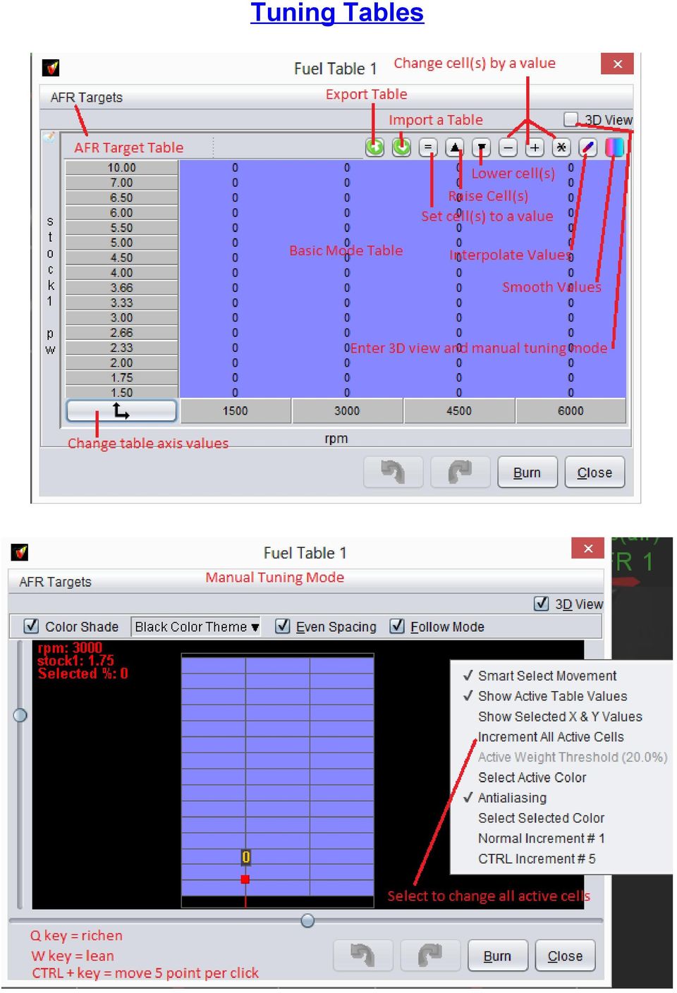
6 Tuning Tables
 Info Note: Autotune is NOT moment of time. It collects data as you drive.")
7 The injector output signals from the stock ecm determine the specific areas under any given situation. But here is some examples of the table areas used in the different circumstances. (Advance Mode Table shown) Info Note: Autotune is NOT moment of time. It collects data as you drive. And knows every piece of information and data under all repeating circumstances and adjusts tuning for statistical averages. (in layman terms - it doesn't chase its tail!!!!)


8 Autotune Note: Not normally ever required is adjusting the Lambda Delay setting. This is for really wild builds with huge throttle bodies and cams that allow alot of air into the exhaust at low rpm. We can set the sensor timing so AT takes measurements at the proper time, ignoring the fresh oxygen. Monster Autotune really is vastly versatile, adjustable, accurate and unmatched.


9 Advanced Tuning This section is only for advanced uses and not normally required. Calibrate TPS menu option is not used in the Fuel Monster application. Acceleration Enrichment: The powerful tuning tables allow full control and tuning of the stock acceleration fuel. However, if the very rare need should ever arise for addition fuel during the initial acceleration or throttle movement, we have provided a means to do so here. Accel Threshold: Sets the amount the input pulsewidth has to change in order for the FM acceleration fuel to be triggered. Fuel to Add: Sets the % of extra fuel to add. Number of Injections to Add Fuel: Sets the number of fuel injections to add the additional % of fuel. Autotune Filter's: These settings are preset for the user. However, having a powerful and real Autotune is having the ability operate as required under any instance. One of the greatest powerful features is ignoring certain situations. And knowing when to ignore them. There is many instances where sudden input pulsewidth greatly changes or AFR reading spikes occur. This is useless information that we don't want to use for tuning. The blue icon question marks in the software give setting details and hints. If you have big cams and your OEM pulsewidth is very jumpy and trigger the accel filter, raise the Accel Threshold value. Try 50% - 100% to enable tuning and not filter out the erratic behaviour.


10 With these settings, we basically want to set them as to ignore the stock ecm acceleration fuel and the decel fuel cut or injector cut. We want to Autotune/adjust the pulsewidth as a decision from the ecm. And that is under a steady state or reading. Not transitional signals. However, there may be instances or builds that you want or need to adjust the stock acceleration fuel quite aggressively. And you can turn the acceleration filter time down or completely off (0 sec and/or high threshold of 1000%) to do so. Acceleration Trigger Threshold: Sets the point where accel filter is triggered. (based on the % the input pulsewidth changes / rises to add more fuel with quick throttle openings). The filter times taper from the low value to the high value between the rpm entries. Since OEM acceleration fuel is always very high at low rpm to very little or none at high rpm, we filter longer at low rpms and less at high rpms. The filter time tapers between entries. Low rpm: Sets the rpm where the low filter time is fully applied. Filter Time: Time to wait before Autotuning again at low rpm. High rpm: Sets the rpm where the high filter time is applied. Filter Time: Time to wait before Autotuning again at high rpm. Decel Trigger Threshold: Sets the point where decel mode filter is triggered. (based on the % the input pulsewidth changes when throttle is closing or closed. Stock pulsewidths drop to varying degrees or the injectors can shut right off in OEM decel mode) Since at high rpm, coast down (decel) is longer than at low rpm, we filter longer at higher rpm and less at lower rpm. Low rpm: Sets the rpm where the low filter time is fully applied. Filter Time: Time to wait before Autotuning again at low rpm. High rpm: Sets the rpm where the high filter time is applied. Filter Time: Time to wait before Autotuning again at high rpm.
 to do so. Acceleration Trigger Threshold: Sets the point where accel filter is triggered.")
QUICK START GUIDE 199R10546
 QUICK START GUIDE 199R10546 1.0 Overview This contains detailed information on how to use Holley EFI software and perform tuning that is included within the software itself. Once you load the software,
CurveMaker v2.1 DYNAFS programmable ignition software
 CurveMaker v2.1 DYNAFS programmable ignition software Dynatek 164 S Valencia St. Glendora CA 91741 phone (626)963-1669 fax (626)963-7399 Contents 1) Installation...1 2) Overview...1 3) Programming a Curve...4
Throttle Body Fuel Injection
 Throttle Body Fuel Injection Initial Calibration of the TBI Disclaimer The author of this presentation assumes NO responsibility for information provided causing the owner to modify or alter their motorhome
PLEASE READ ALL DIRECTIONS BEFORE STARTING INSTALLATION
 PARTS LIST FUEL AND IGNITION 2012-2014 Yamaha T-Max 530 Installation Instructions 1 Power Commander 1 USB Cable 1 Installation Guide 2 Power Commander Decals 2 Dynojet Decals 2 Velcro strips 1 Alcohol
Istruzioni per regolatore elettronico dell iniezione
 Istruzioni per regolatore elettronico dell iniezione Thank you for choosing the Free Spirits Fuel Injection Module. The module is only usable for the following models: Street Triple 2008-2011 Speed Triple
NISSAN FIGARO FAULT CODES AND DIAGNOSTICS
 NISSAN FIGARO FAULT CODES AND DIAGNOSTICS The Nissan Figaro uses an engine management system with the acronym ECCS you ll see it in large letters on the plenum box when you open the bonnet. It stands for
Parts List. Navigation
 Parts List quantity description 1 LCD-200 Display 1 LCD-200 Display cable 1 CD-ROM 2 dual lock or velcro 1 1GB SD card (optional) 1 CAN termination plug Navigation Main Menu Begin Log/Stop Log page 4 Log
PLEASE READ ALL DIRECTIONS BEFORE STARTING INSTALLATION
 Parts List 2012-2013 Honda CBR1000RR Installation Instructions 1 Power Commander FC 1 USB Cable 1 Installation Guide 2 Dynojet Decals 2 Velcro 1 Alcohol swab 1 O2 Optimizer THE IGNITION MUST BE TURNED
well as pulses from a magnetic driveshaft sensor or a magnetic speedometer cable sensor.
 1. Overview The Maximizer 4 progressive nitrous controller operates one or two separate stages of nitrous based on either time, RPM, MPH, throttle percentage or boost pressure. Whether your engine is naturally
QUICK TUNE EFI INSTRUCTION MANUAL
 QUICK TUNE EFI INSTRUCTION MANUAL Step 1: Loading the CB quick Tune Software to your PC A) Take the CB Quick Tune installation CD and load it into your PC. A window will pop up asking to have all programs
ECU MS 3 Sport GT3 Cup. Quick Start Manual
 ECU MS 3 Sport GT3 Cup Quick Start Manual V1.0 11/6/2015 Table of Contents Table of Contents 1 Welcome... 3 1.1 Hardware Checklist... 3 1.2 Hardware Installation... 3 1.3 Software Installation... 3 2 Tools:
SE05: Getting Started with Cognex DataMan Bar Code Readers - Hands On Lab Werner Solution Expo April 8 & 9
 SE05: Getting Started with Cognex DataMan Bar Code Readers - Hands On Lab Werner Solution Expo April 8 & 9 Learning Goals: At the end of this lab, the student should have basic familiarity with the DataMan
Tekin 255 Update For RX8, RSX and RS ESCs
 Tekin 255 Update For RX8, RSX and RS ESCs This wiki provides all the information that you will need to understand your Tekin Brushless ESC settings. This will be updated with any changes as needed. We
Automotive Sensor Simulator. Automotive sensor simulator. Operating manual. AutoSim
 Automotive sensor simulator Operating manual AutoSim Contents Introduction.. page 3 Technical specifications.... page 4 Typical application of AutoSim simulator..... page 4 Device appearance... page 5
BOSCH D-JETRONIC Volkswagen: Type 3 & 4
 BOSCH D-JETRONIC Volkswagen: Type 3 & 4 MANIFOLD PRESSURE CONTROL SYSTEM (MPC) DESCRIPTION The Bosch D-Jetronic electronic fuel injection system is composed of 3 major subsystems: the air intake system,
Transmitter Interface Program
 Transmitter Interface Program Operational Manual Version 3.0.4 1 Overview The transmitter interface software allows you to adjust configuration settings of your Max solid state transmitters. The following
REC FIM LOCKPICK INSTALLATION OPTIONS
 REC FIM LOCKPICK INSTALLATION OPTIONS TM PLUG INTO RADIO PLUG WHITE CONNECTOR INTO RADIO PLUG AND PLAY RADIO CONNECTORS UNPLUG ORIGINAL RADIO GRAY CONNECTOR THEN PLUG IN HERE AFTERMARKET FRONT CAMERA VIDEO
Signature and ISX CM870 Electronics
 Signature and ISX CM870 Electronics Cummins West Training Center System Description General Information The Signature and ISX CM870 engine control system is an electronically operated fuel control system
STEELSERIES FREE MOBILE WIRELESS CONTROLLER USER GUIDE
 STEELSERIES FREE MOBILE WIRELESS CONTROLLER USER GUIDE INTRODUCTION Thank you for choosing the SteelSeries Free Mobile Controller! This controller is designed by SteelSeries, a dedicated manufacturer of
ECUs and Engine Calibration 201
 ECUs and Engine Calibration 201 Jeff Krummen Performance Electronics, Ltd. www.pe-ltd.com Page 1 Before we get started.. ECUs and Engine Calibration 201 The goal of this presentation is to explain the
CAUTION: CAREFULLY READ INSTRUCTIONS BEFORE PROCEEDING. NOT LEGAL FOR SALE OR USE IN CALIFORNIA OR ON ANY POLLUTION CONTROLLED VEHICLES.
 Twin Tec Installation Instructions for Twin Cam Ignition CAUTION: CAREFULLY READ INSTRUCTIONS BEFORE PROCEEDING. T LEGAL FOR SALE OR USE IN CALIFORNIA OR ON ANY POLLUTION CONTROLLED VEHICLES. OVERVIEW
Quick Start Guide RIVA/Athena Sea-Doo ECU
 Quick Start Guide RIVA/Athena Sea-Doo ECU PART# - RS11891-ECU-DC APPLICATION(S): Sea-Doo 260/255/215hp icontrol Models RIVA/Athena ECU Manager Web Site: www.rivaathena.com NOTE: YOU MUST PERFORM PHYSICAL
DIAGNOSIS SYSTEM (3S GTE and 5S FE)
") Diagnosis System (3SGTE and 5SFE) FI39 DIAGNOSIS SYSTEM (3SGTE and 5SFE) DESCRIPTION The ECM contains a builtin, selfdiagnosis system by which troubles with the engine signal network are detected and a
Diagnosis System (3SGTE and 5SFE) FI39 DIAGNOSIS SYSTEM (3SGTE and 5SFE) DESCRIPTION The ECM contains a builtin, selfdiagnosis system by which troubles with the engine signal network are detected and a
Guide to the... Nissan Leaf. Completely harmless fun with. City Car Club 100% electric
 Guide to the... Nissan Leaf Completely harmless fun with City Car Club 100% electric Contents 1. First arrival at the car 2. Starting the car 3. Basic controls 4. Getting the most from the battery 5. Finished
LT1 Tune Kit Quick Start Guide
 LT1 Tune Kit Quick Start Guide Revision D Page 1 Table of Contents Introduction... 3 Minimum PC Requirements... 3 Program Installation... 3 Registering the Program... 4 Installing the USB/ALDL Interface
WIRING HARNESS FOR AS635P4. BLUE PLUG RED, BLUE, BLACK, WHITE - Plug in dual stage sensor harness
 WIRING HARNESS FOR AS635P4 ANTENNA NOT USED 5 PIN WHITE PLUG 2 PIN WHITE PLUG GREEN - PARKING BRAKE INPUT (-) BLUE - NOT USED 3 PIN BLUE PLUG RED, BLUE, BLACK, WHITE - Plug in dual stage sensor harness
BINARY EDITOR GETTING STARTED
 BINARY EDITOR GETTING STARTED AUTHOR DATE REVISION Clint Garrity 12 Aug 2009 A TABLE OF CONTENTS MODIFICATIONS TO THE DOCUMENT...3 1 INTRODUCTION...4 1.1 Scope... 4 1.2 Structure... 4 1.3 Definitions...
ECUMASTER EMU. Firmware EMU
 ECUMASTER EMU CHANGE LOG Version 1.016 Firmware EMU Critical bugs Important bugs 1) Coild dwell time calculations corrected for low tooth count trigger wheels, 2) Idle control valves bug fixed Low priority
ADRENALINE TRUCK PERFORMANCE
 ADRENALINE TRUCK PERFORMANCE EFILive AutoCal Customer Quick Start Guide (No Tunes Loaded) Idaho Rob www.atptrucks.com (208) 685-1000 Table Of Contents 3. - Getting Started 5. - Reading Your Stock Tune
How To Program An Nxt Mindstorms On A Computer Or Tablet Computer
 NXT Generation Robotics Introductory Worksheets School of Computing University of Kent Copyright c 2010 University of Kent NXT Generation Robotics These worksheets are intended to provide an introduction
PUSH BUTTON START INSTALLATION MANUAL
 PUSH BUTTON START INSTALLATION MANUAL ALTHOUGH THIS PRODUCT HAS BEEN THOROUGHLY TESTED KPIERSON TECHNOLOGIES ASSUMES NO RESPONSIBILITY FOR ANY DAMAGE THAT MAY RESULT BY THE INSTALLATION OF THIS PRODUCT.
Diagnostic Fault Codes For Cummins Engines
 Section - Diagnostic Fault Codes For Cummins Engines Applies to Engine Models T, T, QSL T, QSM, QS, QSK9, QSK, QST, QSK//8 Note: These fault codes are current at date of publication. Always refer to engine
DELLORTO. Instructions Manual. Deuss Service Tool For ECS System ECU. Dell Orto Deuss Service Tool instruction manual Page 1 of 11.
 DELLORTO Deuss Service Tool For ECS System ECU Instructions Manual Dell Orto Deuss Service Tool instruction manual Page 1 of 11 Revision History Level Date Author Change Description and section(s) affected
Corsair Link v2.4 Manual. Initial Set-up. Placing devices within the chassis
 Corsair Link v2.4 Manual Initial Set-up Placing devices within the chassis When you first start up Corsair Link, there will be a list of auto-detected devices on the left column. You can drag and drop
Weather Direct Displays show Lost Forecast (blank boxes in the picture icons)
") Weather Direct Displays show Lost Forecast (blank boxes in the picture icons) Many routine events can cause a Lost Forecast situation. Examples include: Power outage Change batteries Internet down in your
Weather Direct Displays show Lost Forecast (blank boxes in the picture icons) Many routine events can cause a Lost Forecast situation. Examples include: Power outage Change batteries Internet down in your
Contents Installing the ucal Software on your PC/Laptop ucal Programmer Version Connecting the ucal Programmer to your PC/Laptop
 Contents Installing the ucal Software on your PC/Laptop 1 ucal Programmer Version 1 Connecting the ucal Programmer to your PC/Laptop 1 Optional USB Adapter Kit (for ucal) 1 Installing the USB Driver for
Workshop 7 PC Software - Tracker
 Workshop 7 PC Software - Tracker Goal: You will startup and perform advanced setup functions using Tracker PC software. You will also setup equations to control MP503 binary outputs. The Binary Output
System update procedure for Kurio 7 (For build number above 110)
") System update procedure for Kurio 7 (For build number above 110) IMPORTANT NOTE: Before starting the procedure, please check your current Android build number, that can be found as follows: exit the Kurio
System update procedure for Kurio 7 (For build number above 110) IMPORTANT NOTE: Before starting the procedure, please check your current Android build number, that can be found as follows: exit the Kurio
POWERSPORTS DYNAMOMETER HARDWARE AND SOFTWARE
 POWERSPORTS DYNAMOMETER HARDWARE AND SOFTWARE DYNOWARE RT DYNAMOMETER HARDWARE DYNOWARE RT THE NEXT GENERATION OF DYNOJET DYNAMOMETER ELECTRONICS AND SOFTWARE HAS ARRIVED. DynoWare RT is the next generation
30-71XX Infinity Quick Start Guide STOP! THIS PRODUCT HAS LEGAL RESTRICTIONS. READ THIS BEFORE INSTALLING/USING!
 Instruction Manual 30-71XX Infinity Quick Start Guide STOP! THIS PRODUCT HAS LEGAL RESTRICTIONS. READ THIS BEFORE INSTALLING/USING! THIS PRODUCT MAY BE USED SOLELY ON VEHICLES USED IN SANCTIONED COMPETITION
BACK PRESSURE MONITOR Operator Display with Exhaust Temperature KIT 194-722
 HEWITT INDUSTRIES 5492 BOLSA AVE. HUNTINGTON BEACH, CA 92649 PH. (714) 891-9300 FAX. (714) 897-7632 WEBSITE: www.hewittindustries.com E-MAIL: sales@hewittindustries.com BACK PRESSURE MONITOR Operator Display
Defi Meter C Application User s Guide
 Defi Meter C Application User s Guide BEFORE INSTALLATION 1 Download the App Search Defi Meter C application through App Store and download the App. 2 Pairing your mobile device with the SMART ADAPTER
Introduction. Drenth Motorsport Gearboxes Fleuweweg 10 7468 AG Enter The Netherlands Phone: +31 (0)547 38 26 96 Fax: +31 (0)547 38 20 65
547 38 26 96 Fax: +31 (0)547 38 20 65") 25.03.0023 Introduction The display comes with a software application. With the software application information shown on the display can be adjusted. There are different modes to adjust: the shape of
25.03.0023 Introduction The display comes with a software application. With the software application information shown on the display can be adjusted. There are different modes to adjust: the shape of
Prislista 2009-11. Alla priser är inkl moms.
 Prislista 2009-11 ECU Alla priser är inkl moms. N-7000 Nemesis-2 (type 1,2,or 3) basic ECU kit including: ECU Short PC adaptor cable N-7002 PC serial lead N-7001 Manual CD with all software 10900:- Mounting
AMS-1000 Multi-Channel Air Management System for Boost Control
 AMS-000 Multi-Channel Air Management System for Boost Control The terminal pin descriptions may also be viewed on screen. See Page 4 of manual for details. Clutch Input Shift Input Scramble Boost Input
Electronic Power Control
 Service. Self-Study Programme 210 Electronic Power Control Design and Function With the Electronic Power Control system, the throttle valve is actuated only by an electric motor. This eliminates the need
Installation Guide (No Router)
") Installation Guide (No Router) This installation guide will show you how to get your voip phone service working. This installation guide should be used if you have a standard DSL or cable modem and no
Installation Guide (No Router) This installation guide will show you how to get your voip phone service working. This installation guide should be used if you have a standard DSL or cable modem and no
EZ-EFI Self Tuning Fuel Injection System
 1 INSTRUCTIONS EZ-EFI Self Tuning Fuel Injection System Thank you for choosing products; we are proud to be your manufacturer of choice. Please read this instruction sheet carefully before beginning installation,
How To Control A Car Alarm On A Car With A Remote Control System
 MODEL CA100 REMOTE CONTROL AUTO ALARM SYSTEM INSTALLATION & OPERATION INSTRUCTIONS WIRING DIAGRAM Black Antenna Wire 6 Pin 6 Pin Mini Connector Valet Switch Blue LED Indicator Blue Wire: (-) 200mA Unlock
Electrical Systems - IQAN Digital Control System. IQAN Control System Components... 5.1.3
 Section 5.1 Electrical Systems - IQAN Digital Control System IQAN Control System Components........................... 5.1.3 IQAN Operational Description: At Machine Startup.....................................
Scan Tool Test Procedures Steve Zack - SPX. Scan Tool Test Procedures
 Scan Tool Test Procedures Steve Zack - SPX Scan Tool Test Procedures Steve Zack - SPX 1 PCM Input Tests While performing many of these tests, to obtain the fastest possible Datastream refresh rate, please
Module 21 Fuel Injectors - Dual Point Injection (DPI)
") Module 21 Fuel Injectors - Dual Point Injection (DPI) Author: Grant Swaim E-mail: sureseal@nr.infi.net URL: www.tech2tech.net Phone: (336) 632-9882 Fax: (336) 632-9688 Postal Address: Tech-2-Tech Website
Module 21 Fuel Injectors - Dual Point Injection (DPI) Author: Grant Swaim E-mail: sureseal@nr.infi.net URL: www.tech2tech.net Phone: (336) 632-9882 Fax: (336) 632-9688 Postal Address: Tech-2-Tech Website
Key. ➍ Micro USB Port ➎ Operating System Toggle Keys ➏ Foam Screen Protectors. ➊ On/Off switch ➋ Bluetooth Connect Button (flashes when searching)
") INSTRUCTION MANUAL ➏ ➋ ➊ Product Features ➎ ➍ ➌ Built-in wireless Bluetooth 3.0 keyboard Compatible across ios, Android, and Windows, enabling you to mix and match with devices Ultra-thin, lightweight
INSTRUCTION MANUAL ➏ ➋ ➊ Product Features ➎ ➍ ➌ Built-in wireless Bluetooth 3.0 keyboard Compatible across ios, Android, and Windows, enabling you to mix and match with devices Ultra-thin, lightweight
E - THEORY/OPERATION
 E - THEORY/OPERATION 1995 Volvo 850 1995 ENGINE PERFORMANCE Volvo - Theory & Operation 850 INTRODUCTION This article covers basic description and operation of engine performance-related systems and components.
MAINTENANCE & TROUBLESHOOTING
 MAINTENANCE & TROUBLESHOOTING This section describes how to: clean the lens clean the fan intake filter replace the projection lamp replace the batteries in the remote control use the Kensington lock feature
PeopleGIS Leica RTK GPS Instructions
 PeopleGIS Leica RTK GPS Instructions Equipment List GG02 Receiver (Antenna) GPS Range Pole Zeno Tablet MiFi MiFi External Battery Carrying Case 1) Turning on the MiFi Power on the MiFi. This little gadget
Six-servo Robot Arm. DAGU Hi-Tech Electronic Co., LTD www.arexx.com.cn. Six-servo Robot Arm
 Six-servo Robot Arm 1 1, Introduction 1.1, Function Briefing Servo robot, as the name suggests, is the six servo motor-driven robot arm. Since the arm has a few joints, we can imagine, our human arm, in
Diagnosing and Understanding Starting Problems on the ZR-1 Marc Haibeck 28-Sep-13
 Diagnosing and Understanding Starting Problems on the ZR-1 Marc Haibeck 28-Sep-13 There are three basic failure conditions: - A VATS security system lockout - A click from the starter solenoid but no engine
BATTERY MANAGEMENT SYSTEM
 BATTERY MANAGEMENT SYSTEM User s manual Revision 1 In this user s manual you will find a list of characteristics, setup and installation steps and recommendations for the EMUS Battery Management System.
Using the VEX Cortex with ROBOTC
 Using the VEX Cortex with ROBOTC This document is a guide for downloading and running programs on the VEX Cortex using ROBOTC for Cortex 2.3 BETA. It is broken into four sections: Prerequisites, Downloading
Harley-Davidson. Screamin Eagle Pro Super Tuner. User s Manual
 Harley-Davidson Screamin Eagle Pro Super Tuner User s Manual Table of Contents Section 1 Introduction...4 Kit Contents...4 Disclaimer and Warnings...4 How to Use This Manual...5 Section 2 Introduction
ILISC515-A Shift Interlock (Manual Lift Door) 2015 Ford Transit, 3.7L and 3.5L
 2015 Ford Transit, 3.7L and 3.5L") An ISO 9001:2008 Registered Company ILISC515-A Shift Interlock (Manual Lift Door) 2015 Ford Transit, 3.7L and 3.5L Introduction The ILISC515-A is a microprocessor driven system for controlling wheelchair
An ISO 9001:2008 Registered Company ILISC515-A Shift Interlock (Manual Lift Door) 2015 Ford Transit, 3.7L and 3.5L Introduction The ILISC515-A is a microprocessor driven system for controlling wheelchair
Contents Contents Contents Overview Charging your headset Wearing the headset Powering on the headset Connecting your headset for dictation
 1 Contents Contents Contents 2 Overview 3 Charging your headset 4 Wearing the headset 4 Powering on the headset 4 Connecting your headset for dictation 5 The adapter 5 Adjusting your computer's audio settings
Digital I/O: OUTPUT: Basic, Count, Count+, Smart+
 Digital I/O: OUTPUT: Basic, Count, Count+, Smart+ The digital I/O option port in the 4-Series provides us with 4 optically isolated inputs and 4 optically isolated outputs. All power is supplied externally.
e-4 AWT07MLED 7 Q TFT LCD MONITOR (LED Backlighted) USER MANUAL
 USER MANUAL") Thank you for purchasing our product. Please read this User s Manual before using the product. Change without Notice AWT07MLED 7 Q TFT LCD MONITOR (LED Backlighted) USER MANUAL e-4 SAFETY PRECAUTIONS Federal
Thank you for purchasing our product. Please read this User s Manual before using the product. Change without Notice AWT07MLED 7 Q TFT LCD MONITOR (LED Backlighted) USER MANUAL e-4 SAFETY PRECAUTIONS Federal
UltraCade Multi-Game System Frequently Asked Questions
 The UltraCade Frequently Asked Questions (FAQ) is a collected list of the most common questions asked by our customers. Please make sure your Tech Support team has a copy of these questions to better serve
How to read this guide
 How to read this guide The following shows the symbols used in this Quick start guide with descriptions and examples. Symbol Description Example P oint Reference Caution [ ] This symbol explains information
INSTALLATION INSTRUCTIONS BOOST CONTROLLER. Pro Control Input (Optional) Tach. Signal. Speed. Gray. Signal. Green Blue. Orange.
 Tach. Signal. Speed. Gray. Signal. Green Blue. Orange.") 2650-1706-00 INSTALLATION INSTRUCTIONS BOOST CONTROLLER WARNING! The installation of the Auto Meter Boost Controller is recommended only for experienced technicians. This product may damage your engine
2650-1706-00 INSTALLATION INSTRUCTIONS BOOST CONTROLLER WARNING! The installation of the Auto Meter Boost Controller is recommended only for experienced technicians. This product may damage your engine
User's Guide. Integrating Sound Level Datalogger. Model 407780. Introduction
 User's Guide 99 Washington Street Melrose, MA 02176 Phone 781-665-1400 Toll Free 1-800-517-8431 Visit us at www.testequipmentdepot.com Back to the Extech 407780 Product Page Integrating Sound Level Datalogger
Via Raffaello,33/A - 42100 Reggio Emilia Italia Tel +39 0522.514.461 Fax +39 0522 514469 - E-mail: aftersales@landi-gas.
 Trouble Shooting Solving problems with LSI-NSI software Update to version 2.1.0 1/14 Rev.0 2/14 Rev.0 CONTENTS 1.1. Switching from petrol to gas PAGE 4 1.2. Drop at medium-high speeds PAGE 5 1.3. Functioning
How to use the OMEGALOG software with the OM-SQ2010/SQ2020/SQ2040 Data Loggers.
 How to use the OMEGALOG software with the OM-SQ2010/SQ2020/SQ2040 Data Loggers. OMEGALOG Help Page 2 Connecting Your Data Logger Page 2 Logger Set-up Page 3 Download Data Page 8 Export Data Page 11 Downloading
DTC P0125 Insufficient Coolant Temperature for Closed Loop Fuel Control
 EINE (5VZFE) DI195 DI8YY02 DTC P0125 Insufficient Coolant Temperature for Closed Loop Fuel Control CIRCUIT DESCRIPTION To obtain a high purification rate of the CO, HC and x components of the exhaust gas,
Installation Instructions for 30-4100 Gauge-Type UEGO Controller
 Installation Instructions for 30-4100 Gauge-Type UEGO Controller WARNING: This installation is not for the electrically or mechanically challenged! Use this sensor with EXTREME caution! If you are! uncomfortable
Article : A-451. RPM amplifyer. Technical card : 20-08-2007 Updated : 21-05-2008
 Technical card : 20-08-2007 Updated : 21-05-2008 Article : A-451 RPM amplifyer Application : It is an electronic amp with microprocessor which adapts the RPM signals coming from nearly all types of engines
VEHICLE SPEED CONTROL SYSTEM
 PL VEHICLE SPEED CONTROL SYSTEM 8H - 1 VEHICLE SPEED CONTROL SYSTEM TABLE OF CONTENTS page DESCRIPTION AND SPEED CONTROL SYSTEM...1 SPEED CONTROL SERVO-PCM OUTPUT....2 SPEED CONTROL SWITCHES PCM INPUT...2
PC SERIAL INTERFACE FOR LAMBDA GAS CONTROL LGC-700
 PC SERIAL INTERFACE FOR LAMBDA GAS CONTROL LGC-700 INDEX 1- Introduction 2- AGI-PRO Program Set-up 3- AGI-PRO Program Use 3.1- Interface Link 3.2- How Start AGI-PRO program 3.2-1. Page MONITOR 3.2-2. Page
125 8880 telstra.com/ppmbb visit a telstra store or partner GETTING TO KNOW YOUR
 FOR MORE INFORMATIoN: 125 8880 telstra.com/ppmbb visit a telstra store or partner GETTING TO KNOW YOUR Telstra PRE-paid 4G wi-fi LET S GET THIS SHOW ON THE ROad WHAT S INSIDE Your Telstra Pre-Paid 4G Wi-Fi
Quick Instructions for Setting up Swe-dish.
 Quick Instructions for Setting up Swe-dish. Physical Set-up. 1. Pick a location with a hard mainly level surface (feet on bottom of suitcase are adjustable if surface is uneven). 2. Align the Suitcase
1. Introduction... 3. 2.Fixture exterior view... 3. 3. Connecting the Robe Universal Interface... 4. 3.1 Software update of the fixture...
 1 Table of contests 1. Introduction... 3 2.Fixture exterior view... 3 3. Connecting the Robe Universal Interface... 4 3.1 Software update of the fixture... 4 3.2 Connecting a DMX console to the Media Fusion...
USER INSTRUCTIONS FOR GET PORTABLE 12k BTU AIR CONDITIONER MODEL No. GPACU12HR
 USER INSTRUCTIONS FOR GET PORTABLE 12k BTU AIR CONDITIONER MODEL No. GPACU12HR CONTENTS Introduction Safety Notes Identification of parts Installation instructions Operation instructions Maintenance Troubleshooting
Quick Start Guide Ski Doo Snowmobiles
 Thank you for purchasing Candoopro! Please read the following information before using the system for the first time. If you have any questions about the use of the system, please contact us at Sales@candoopro.com,
AimTrak Playstation 2 User Guide
 AimTrak Playstation 2 User Guide http://www.ultimarc.com 1 Table of Contents Contents...2 1. Introduction...2 2. Buttons and Wiring...3 3. Setup Guide...4 3.1 A Note on Firmware...4 3.2 Initial Setup....4
USER MANUAL OPERATION AND USE OF CAR WITH. Diego G3 / NEVO SEQUENTIAL GAS INJECTION SYSTEM
 USER MANUAL OPERATION AND USE OF CAR WITH Diego G3 / NEVO SEQUENTIAL GAS INJECTION SYSTEM Page 2 z 7 Table of contents 1. STARTING THE ENGINE... 3 2. CONTROL PANEL... 3 2.1 Indication of the current level
G-100/200 Operation & Installation
 G-100/200 Operation & Installation 2 Contents 7 Installation 15 Getting Started 16 GPS Mode Setup 18 Wheel Sensor Mode Setup 20 Fuel Calibration 23 Basic Operation 24 Telemetery Screen 27 Entering a Distance
Renewable Energy Monitor User Manual And Software Reference Guide. sales@fuelcellstore.com (979) 703-1925
 703-1925") Renewable Energy Monitor User Manual And Software Reference Guide sales@fuelcellstore.com (979) 703-1925 1 Introducing the Horizon Renewable Energy Monitor The Renewable Energy Monitor is an educational
Renewable Energy Monitor User Manual And Software Reference Guide sales@fuelcellstore.com (979) 703-1925 1 Introducing the Horizon Renewable Energy Monitor The Renewable Energy Monitor is an educational
DTC Summaries. V8 AJ26 Engine Management 1997. Refer to page 2 for important information regarding the use of this Summary.
 DTC Summaries V8 AJ26 Engine Management 1997 OBD II MONITORING CONDITIONS: When testing for DTC reoccurrence, it can be determined if the Service Drive Cycle was of sufficient length by performing a PDU
ECF-1 User Manual. P/N 3910 kit does not include flex fuel sensor. The ECF-1 is compatible with GM P/Ns 13577429 and 13577379
 ECF-1 User Manual P/N 3910 kit does not include flex fuel sensor. The ECF-1 is compatible with GM P/Ns 13577429 and 13577379 1. Flex Fuel and Lambda... 2 2. ECF-1... 2 1.1 Changing the ECF-1 s gauge face
tattletale User Guide Consumer unit version 2.48 1 P a g e
 tattletale User Guide Consumer unit version 2.48 1 P a g e Contents Basic 1... 4 Base Unit Features... 4 Initial Setup... 4 Arming... 5 Disarming... 5 Quiet Button... 5 Settings... 5 Settings 2... 6 Quick
5. Tutorial. Starting FlashCut CNC
 FlashCut CNC Section 5 Tutorial 259 5. Tutorial Starting FlashCut CNC To start FlashCut CNC, click on the Start button, select Programs, select FlashCut CNC 4, then select the FlashCut CNC 4 icon. A dialog
MFI - Instructional Manual Version 05.01
 58 Graniet Street, Jet Park, JHB - Tel: 011 97195 - Fax: 011 978197 ww w. go tech. co. za MFI - Instructional Manual Version 05.01 Index: Introduction 1 Before You Begin 1 Basic Tools Required Basic Components
mdm-mp3 minidirector with MP3 Player
 minidirector with MP3 Player User Manual December 15, 2014 V1.02 Copyright Light O Rama, Inc. 2007, 2008 Table of Contents Introduction... 4 What s in the Box... 4 Hardware Utility Version... 5 Important
Note: This information obtained from internet sources and not verified- use at your own risk!!!!
 Cummins Engine Diagnostic Fault Codes for 2003 and later engines (generally for 2004 and later Alpines; see page 13 for earlier engine diagnostic codes): Note: This information obtained from internet sources
Using a Laptop Computer with a USB or Serial Port Adapter to Communicate With the Eagle System
 Using a Laptop Computer with a USB or Serial Port Adapter to Communicate With the Eagle System ECU DB9 USB 20-060_A.DOC Page 1 of 18 9/15/2009 2009 Precision Airmotive LLC This publication may not be copied
SAS light Check Engine Malfunction Indicator Lamp
 SAS light Check Engine Malfunction Indicator Lamp Here's how to do it: In car ECM Diagnostics/ECM Reset procedure: 1) Sit in the driver's seat. 2) Turn the ignition key to the ON position and wait three
Portable Air Conditioner. OWNER S MANUAL Read these instructions before use. Model: MF08CESWW. Voltage rating: 115V~60Hz Power rating : 800W
 MODE ALARM Portable Air Conditioner OWNER S MANUAL Read these instructions before use 8 Model: MF08CESWW Voltage rating: 115V~60Hz Power rating : 800W Customer Support : 1-800-474-2147 For product inquiries
2013 G Miller. 3 Axis Brushless Gimbal Controller Manual
 2013 G Miller 3 Axis Brushless Gimbal Controller Manual P a g e 2 When you receive your 3 axis controller board from dys.hk in the packet will be the following items the sensor 3rd Axis board the main
K-Type Thermocouple Sensor User s Guide
 K-Type Thermocouple Sensor User s Guide 1 TABLE OF CONTENTS: 1 INTRODUCTION... 2 2 TYPICAL APPLICATION:... 2 3 INSTALLATION RULES:... 2 3.1 Connecting the sensor to M1/MD4 data logger:... 2 3.2 Connecting
FTDI VCP DRIVER (free) (WIN/MAC/LINUX) http://www.ftdichip.com/drivers/vcp.htm
 (WIN/MAC/LINUX) http://www.ftdichip.com/drivers/vcp.htm") 002 - CONNECTING THE PRINTER Now that you have an idea what 3D printing entails, we can continue and connect the printer to your computer. First make sure you have a computer with a decent amount of RAM
002 - CONNECTING THE PRINTER Now that you have an idea what 3D printing entails, we can continue and connect the printer to your computer. First make sure you have a computer with a decent amount of RAM
AEO Head Movement Tracker X-GYRO 1000 USER MANUAL(V1.1bata 20091019)
") AEO Head Movement Tracker X-GYRO 1000 USER MANUAL(V1.1bata 20091019) Introduction: X-GYRO 1000 is a two axis head tracking system, based on G sensor technique, designed for tracking complicated three-dimensional
AEO Head Movement Tracker X-GYRO 1000 USER MANUAL(V1.1bata 20091019) Introduction: X-GYRO 1000 is a two axis head tracking system, based on G sensor technique, designed for tracking complicated three-dimensional
CareSentinel Set Up Guide for Android Devices
 CareSentinel Set Up Guide for Android Devices Compatible Devices: Only devices running Android 4.3 or newer support Bluetooth Smart. Any smart phone or tablet running an Android operating system older