MSK-8900M Industrial Sewing Machine
|
|
|
- Cory Armstrong
- 7 years ago
- Views:
Transcription
1 MSK-8900M Industrial Sewing Machine INSTRUCTION MANUAL

2 CONTENTS Operation instruction. Brief introduction. Main specifications. Main parts name 4. The method of installation 5 5. Pareparation before sewing Sewing Adjusting the tension of thread 8 8. Maintenance Correct adjustment 0 Parts manual. Machine casting components 4 5. Needle bar, thread take-up components 6 7. Presser foot components Feed components 0 5. Rotary hook components Lubrication components Accessories 8 9

3 OPERATION INSTRUCTION

4 4. Brief introduction. Main specifications MSK-8900M/H high speed straight lockstitch sewing machine adopts single needle, needle bearing link to take up thread, small hook to catch loop which forms lockstitch seam. It features high precise bevelgear for driving upper and lower shafts, dial stitch length regulator, lever type forward and reverse feed mechanism, full automatic lubricating system assures reliable lubrication. With the features of reasonable design, beautiful apperance, precisely manufacture, little vibration and lower noise, it s a good machine for the makers of garments, suitcase, leather goods, shoes and caps, etc. Model Applications Max. Sewing speed Max. Stitch length Needle bar stroke Presser foot lift height Height of feed dog Needle Hook Lubrication Motor power MSK-8900M Medium - and heavy - weight materials 400.s.p.m. 4.mm mm 0.8mm DB 4# 6mm by hand mm by knee Automatic lubrication 70W MSK-8900H Heavy - weight materials 500.s.p.m. 5mm 5mm.mm DB # Small auto - lubricating hook. Main parts name (Fig. ) 7 4 Needle bar Thread take-up lever cover Oil window Hand wheel Stitch dial Feed lever Pressure adjusting screw Bobbin winder Belt guard The method of installation a. Installing the oil pan (Fig. ) () Put the vibration-proof pad (black) and (double color) under the four corners of oil pan ;

5 b () Put the oil pan into the cutouts of table and fix it by nails ; () put the machine casting hinge cushion into the cutouts of table and fix it by nails.. Installing the machine head (Fig. ) () Insert the knee lifting rod ; () Insert the casting hinge to the hole in the bed; () Put the hinge in the cushion and put the head on the pad ; (4) Inset the machine head supporter in the table. Notice: Be sure to full inset the supporter in the table Otherwise it may cause danger while put the machine head down.
 Inset the machine head supporter in the table.")
6 . Installing the knee lifter (Fig. 4) Install the knee lifter on the knee lifter hinge shaft and fix it by screw Adjusting the knee lifter mechanism (Fig. 5) () Lay down the presser foot lifting bar to lower the presser foot ; () Loosen the nut ; () Press the knee lifter plate cover to make movement amount of the knee lifter positioning bracket about mm, then adjust the screw ; (4) After adjustment, tighten the nut. (5) Loosen the nut ; (6) Adjust screw to make its length above the bracket 8mm; (7) Adjust screw, the clearance between presser foot and needle plate should be less than mm when the knee lifter is pressed to its maximum position; (8) After adjustment, tighten the nut Installing the V-belt (Fig. 6) () Lower the machine head and install the belt on the hand wheel and motor pulley; () Press the belt by forefinger with the power of 4.9N (500gf), adjust the nut to make the belt a slack of 0~4mm. 6
 Loosen the nut ; (6) Adjust screw to make its length above the bracket 8mm; (7) Adjust screw, the clearance between presser foot and needle plate should be less than mm when the knee lifter is")
7 G F E D C B A 0~ «7 6. Connecting pedal with lever of clutch motor (Fig.7) () The optimum tilt angle of pedal A against floor is approx.0 ~0. () Adjust the clutch of motor E to make the rod B and the clutch lever C run in one line. () When runing, the machine balance wheel G should rotate counter - clockwise observed form opposite side of the balance wheel, the motor D rotates in the same direction. The rotation of motor can be reversed by reversing the plug of power ( turn over 80 ) (4) Adjust the tension of V-belt F by moving the motor upward or downward. The proper tension of V-belt is a slack of 0~mm when the V-belt is depressed by forefinger Installing the bobbin winder (Fig.8) () Press the winding controlling lever to its utmost position; () Install the winder parallel with the belt hole in the table, be sure that the belt can be pressed to 5mm by winder pulley ; () Fix the winder by two wooden screw ; (4) When the lever restores its original position, be sure that the clearance between winder pulley and belt is 8mm. 9a 8. Installing the belt guard (Fig.9) () Install the three screws on the machine casting, please don't tighten the screws too tight. -b -c -a
 (4) Adjust the tension of V-belt F by moving the motor upward or downward.")
8 () Lay down the machine head and install the belt guard in the screw bar and screw, tighen the screw -a. () Raise the machine head and tighten the screw. (4) Aim the gib of upper belt guard to the screw -b, and cover the hand wheel by upper belt guard. (5) Fix the upper belt guard by screw -b, -c and. (6) Install the lower belt guard and there should be a overlap of mm with belt guard, tighten the two screw. (7) Insert the plate between belt guard and. (8) Move the plate along the groove of belt guard as far possible. (9) Be sure that there should be not any clearance between belt guard and plate. (0) Tighten the two screws (refer to step ). -b -c 9b 9. Oiling () Please pull out the power plug to avoid hurting; () lay down the machine head and fill the oil in the oil pan till to the mark of HIGH 0 Notice: Please use sewing oil 8# Please replenish the oil when the level of oil approaches to the mark of LOW 5. Preparation before sewing. Installing the needle (Fig. ) () Turn the hand wheel to lift the needle bar to its highest position; () Loosen the needle set screw ; () Make the needle groove to the left side of the operator, then fully insert the needle shank until to the bottom of the needle bar socket, tighten the set screw. Long groove Frontal
 Move the plate along the groove of belt guard as far possible. (9) Be sure that there should be not any clearance between belt guard and plate. (0) Tighten the two screws (refer to step ).")
9 . Uninstalling the bobbin case (Fig. ) () Turn the hand wheel to lift the needle above the needl plate; () Open the opener and uninstall the bobbin case; () Release the opener and uninstall the bobbin. Winding the bobbin thread (Fig. ) () Turn the power on; () Install bobbin to bobbin winder shaft, push the lever down to the utmost position; () Wind the thread several circles on the bobbin (4) When the machine running, the bobbin will be wound; (5) After winding, the lever will be released automatically, then uninstall the bobbin. If the thread is wound unevenly. Loosen the screw and move the bracket to the side which the thread is little wound. The winding amount can be adjusted by screw Increase the amount tighten Decrease the amount loosen Please be sure the optimum capacity of thread is filled about 80% of bobbin outside diameter 4 4. Install the bobbin case (Fig. 4) () Put the bobbin into the bobbin case as Fig 4 shown; () Draw the bobbin thread through the slit and pass it under the lace spring plate l () Draw the bobbin thread out of the slit at the top of lace spring plate; (4) Draw the thread and confirm if the bobbin can turn; (5) Hold the opener and put the bobbin case in the hook.
 After winding, the lever will be released automatically, then uninstall the bobbin. If the thread is wound unevenly.")
10 5. Threading the needle thread (Fig. 5) Turn the hand wheel to lift the thread take-up lever to its highest position. 5 About 50mm 5 6. Adjusting the stitch length (Fig. 6) () Turn the stitch dial to make the pin aim at the number on the stitch dial. The more big the number becomes, the more long the stitch length is. Please put the feed lever at the medium position, then the dial can been turned easily Sewing. Sewing method () Turn the switch on; () The sewing begins after step the pedal

11 7. Reverse sewing (Fig.7) When sewing, press down the feed lever to perform reverse sewing, release the lever, the forward sewing is resumed Adjusting the tension of thread strengthen Weaken Bobbin thread Strengthen Weaken. Adjust the tension of thread (Fig. 8) () Adjust the tension of needle thread Lower the presser foot and adjust the nut as shown in the Fig 8 (left) () Adjust the tension of bobbin thread Hold the tip of bobbin thread, the proper tension is that the bobbin case can drops slowly, Adjust the screw as shown in the Fig. Weaken strengthen 9. Adjust the pressure of presser foot (Fig. 9) () Loosen the nut. () Turn the screw to adjust the pressure Under the condition of without slippage, the more small the pressure of presser foot, the more good it is. () Tighten the nut.
 () Loosen the nut.")
12 8. Maintenance (Fig. 0~5) For protect the sewing machine and keep its good performance, the machine must be maintained every day, if the machine is left unused for a long time, please maintain it as following sequence. Lift the presser foot;. Loosen the screw and uninstall the needle plate ;. Clean the dust on the feed dog with a tooth brush; 4. Fix the needle plate by screw Turn the hand wheel slowly to make the needle enter into the center of the hole of needle plate exactly; If the needle cannot enter into the center of the hole of needle plate, Confirm if the needle bends Loosen the screw and adjust the needle plate again. 6. Turn the hand wheel to lift the needle up to the needle plate and confirm if the pinpoint has been damaged, if yes, please change a new one. 7. Lay down the sewing machine 8. Uninstall the bobbin case ; 9. Clean the dust on the hook and check if it has been damaged; 0. Pull the bobbin out of the bobbin case and clean the bobbin case with cloth;. Put the bobbin in the bobbin case and put the bobbin case in the hook.. Open the face plate periodically. Clean the fiber deposits on the needle bar and needle bar bushing with a brush or cloth; 4. Fix the face plate and tighten the screw, If dont t clean periodically, it may cause the possibility of oil exudation or oil leakage or polluting the fabric.

13 4 5. Clean the oil dust with cloth 6. While the oil level is lower than the mark of LOW, please supplement the oil. Please use sewing oil 8# If the oil is dirty, uninstall the screw and replace the fresh sewing oil, also please clean the dust on the magnet and oil pan Lift the machine head 8. Confirm the threading sequence of needle thread; 9. Trial sewing 6 9. Correct adjustment. Adjust the thread take-up spring () Adjust the tension of spring (Fig. 6) The tension standard of thread take-up spring: model MSK-8900M is 0.45~0.4 N ( 5~5gf ) and model MSK-8900H is 0.9~0.49 N ( 0~50gf ) a. Press the needle thread and tighten the nut slightly; b. Test the tension when the bottoms of spring and thread guide are at the same height. c. Turn the screw by a screwdriver to adjust the tension of thread take-up spring <-> 0.5~0.4N (5~5gf) <-5> 0.9~0.49N (0~50gf)
 The tension standard of thread take-up spring: model MSK-8900M is 0.45~0.4 N ( 5~5gf ) and model MSK-8900H is 0.9~0.49 N ( 0~50gf ) a. Press the needle thread and tighten the nut slightly; b.")
14 () The position of thread take-up spring (Fig. 7) lower the presser foot, the clearance between thread take-up spring and the top of thread guide is 6~8 (for MSK-8900M) and 4~6mm (for MSK-8900H) a. Lower the presser foot ; b. Loosen the screw ; c. Turn the thread tension base to adjust it; d. Tighten the screw. ~ ~ 7. Adjust the casting thread guide (Fig. 8) The proper position of casting thread guide is that the screw locates at the center of adjusting range of thread guide When adjustment, Loosen the screw and move the thread guide. For sewing heavy weight materials, please move the thread guide leftward;. For sewing light weight materials, please move the thread guide rightward; More Less 8. Adjust the height of presser foot Lift the presser foot by presser foot lifting bar, the standard height of presser foot is 6mm () Loosen the nut and screw Note: The height A of screw cannot exceed 49mm, otherwise the presser spring and spring rod will be out. () Lift the presser foot by presser foot lifting bar ; () Pull out the rubber plug ; (4) Loosen the screw and move the presser bar upward or downward to make the height of presser foot 6mm (5) Tighten the screw ; (6) Inset the rubber plug; (7) Adjust the pressere of presser foot with screw, then tighten the nut. 9

15 <->0.8mm <-5>.mm 0 4. Adjust the height of feed dog (Fig. 0) The highest height of feed dog against needle plate is 0.8mm. ( For MSK-8900M ) or. mm ( for MSK-8900H) () Turn the hand wheel to lift the feed dog to its highest position; () Loosen the screw ; () Turn the crank and adjust the feed dog supporter ; (4) Tighten the screw. Standarel Front decline Front raise 5. Adjust the angle of feed dog (Fig. ) While the feed dog is at its highest position, the standard angle is that the mark on the shaft inosculates the ones on the feed dog supporter () Turn the hand wheel to lift the feed dog to its highest position; () Loosen the screw ; () Loosen the shaft and adjust it within the range of 90 shown in the Fig. upon the standard position If the materials puckering, adjust the feed dog as Fig A shown; If the materials slippery, adjust the feed dog as Fig B shown; (4) Tighten the screw. After adjustment, the height of feed dog will change, so please adjust the height of feed dog again. 6. Adjust the height of needle bar (Fig. ) When the needle bar is at its lowest position, the second mark a on the needle bar should align with the bottom of needle bar bushing () Locate the needle bar at its lowest position () Pull out the rubber plug () Loosen the screw and adjust the needle bar upward or down ward (4) Tighten the screw (5) Inset the rubber plug
 While the feed dog is at its highest position, the standard angle is that the mark on the shaft inosculates the ones on the feed dog supporter () Turn the hand wheel to lift the feed dog to its")
16 7. Adjust the position between needle bar and feed dog (Fig.) When the feed dog moves down to the position which is same with the surface of needle plate from its highest position,the standard position of needle should be as follows: For light and medium weight materials The surface of feed dog and needle plate should be same and the pinpoint of needle is mm lower than the needle plate For heavy weight materials The surface of feed dog and needle plate shousd be same and there is a clearance of mm between the pinpoint and needle plate () Uninstall the back cover; () Loosen the screw on the cam and screw on the feed cam, slightly turn and adjust the cam and feed cam ( these two cams are connect -ed by pin and should turn alternative side) If the timing of needle is fast, turn as shown in the Fig. A ; if the timing of needle is slow, turn as shown in the Fig. B For avoiding materials misplacing, please make the timing of needle slowly (Fig. B ) For avoiding stitch puckering, please make the timing of needle fast (Fig. A ) Notice: If turn the cam and feed cam overlar -ge as Fig. A Shown, it will make needle broken () After adjustment, tighten the screw and 8. Adjust the position between needle and hook (Fig.4) Lift the needle bar from its lowest position, while the lowest mark on the needle bar aligns with the bottom of needle bar bushing, the tip of hook should aim at the center of needle. () Turn the hand wheel and lift the needle bar to make the mark b align with the bottom of needle bar bushing When the needle is lifted.8mm (for MSK-8900M) or.mm (for MSK-8900H), the clearance between the hole of needle and the tip of hook should be 0~0.5mm () Loosen the screw and make the tip of hoodk aim at the center of needle. the lateral clearance between the tip of hook and needle. should be 0.05mm () tighten the screw 9. Adjust the oil amount of upper shaft and hook (Fig.5) () Upper shaft Uninstall the face plate, turn the screw to adjust the oil amount of upper shaft () Hook Lay down the machine head, turn the screw to adjust the oil amount of hook. After adjustment, let the machine be run for ~ mim. and confirm the oil amount again Stritch Timing fast Starelarcl Timing slow Most <-> <-5> For example: MSK-8900M A b Least <->.8mm <-5>.mm 0~0.5mm 0.05mm B less More 4 5
 Uninstall the back cover; () Loosen the screw on the cam and screw on the feed cam, slightly turn and")
17 PARTS MANUAL

18 .Machine casting components TYPICAL

19 .Machine casting components No. Parts No. Name of parts Qty. Remarks WF-00 7WF-00 7WF-00 7WF-004 7WF-06E 7WF-06F 7WF-007 T-006 7WF-009 7WF-00 7WF-0 7WF-0 7WF-0 7WF-09 T-00C 7WF-04 7WF-04 6T5-008E5 7WF-0 7WF-0A 7WF-00 7WF-0 WF-060 T-00 7WF-08 7WF-0 7WF-05 7WF-09 WF WF-07 7WF-0 7WF-06G 7WF-06G-5 7WF-05 7WF-0 7WF-06H 7WF-06J 7WF-06A 7WF-06B 7WF-06C 7WF-06D 7WF-04 7WF-06I Machine casting Machine bed Supporting rod (long) Supporting rod (short) Thread tension disc Thread tension releasing disc Back cover Rubber plug Rubber plug Rubber plug Rubber plug Rubber plug Model label Rubber plug Rubber plug Tools base Upper thread guide Thread guide Thread guide Thread guide Face plate Cover for thread take-up lever Thread guide Brand label Tension spring Tension spring Thread opening pin Stop disc O-ring Thread tension bracket assembly Thread tension shaft Thread take-up spring Thread releasing pin Thread tension nut 5 4 SM9/" 8 8 SM/64" SM/64" SM/64" 40 SM/64" 40 7 SM/64" SM9/64" 40 6 SM/64" 40 0 For MSK-8900H SM/64" 40 SM/64" 40 4
 Supporting rod (short) Thread tension disc Thread tension releasing disc Back cover Rubber plug Rubber plug Rubber plug Rubber plug Rubber plug Model label Rubber")
20 .Needle, thread take-up components
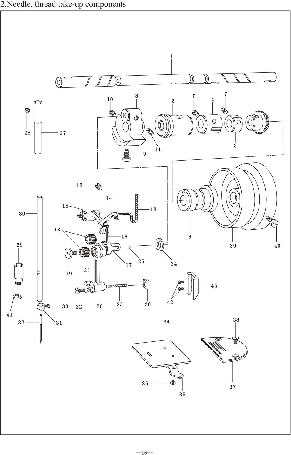
21 .Needle, thread take-up components No. Parts No. Name of parts Qty. Remarks WF-00 7WF-005 7WF-008 7WF-006 WF4-06 7WF-07 WF-008 7WF-06A 7WF-06A-5 7WF-06B WF-0 WF-008 7WF-08 7WF-07A 7WF-07B 7WF-07B-5 7WF-07C 7WF-07C-5 7WF-07D 7WF-07D-5 7WF-07F 7WF-07G 7WF-07G-5 7WF-07H 7WF-07I 7WF-09 7WF-07E T-0 7WF-00 7WF-0 7WF-0 7WF-0-5 7WF-04 T-05 7WF-06 7WF-07 7WF-08C 7WF-08A 7WF-08B 7WF-07 7WF-07-5 WF WF-09 T-007C 7WF-0 T-09 7WF-08 Upper shaft Upper shaft bushing(left) Collar Upper shaft bushing (middle) Upper shaft bushing(rear) Needle bar crank Needle bar crank Oil wick Hinge shaft Thread take-up link Thread take-up link Thread take-up lever assembly Thread take-up lever assembly Thread take-up crank Thread take-up crank Needle bearing Needle bar link Needle bar link Needle bar connector Oil wick Washer Oil felt Slide block Needle bar bushing(upper) Needle bar bushing(lower) Needle bar bushing(lower) Needle bar Needle bar thread ring Needle Slide plate Slide plate spring Needle plate Needle plate Hand wheel Needle bar thread guide Block guide SM5/64" 8 6 SM/4" for MSK-8900H SM9/" 8 SM/4" 40 0 SM/4" SM/4" 8 0 L=50mm For MSK-8900H For MSK-8900H For MSK-8900H SM9/64"X40X.8(Left-twistecl) (For MSK-8900H SM9/64" L=7mm SM5/64" 8 4 For MSK-8900H DB (M)4#(H)# SM/8" SM/" 56. For MSK-8900H SM/64" 40 SM5/64" 8 4 SM/64" 40 8
22 .Presser foot components
23 .Presser foot components No. Parts No. Name of parts Qty. Remarks 7WF5-00 Presser bar 7WF5-00 Presser bar bushing WF WF5-00 Presser spring rod 5 7WF5-004 Presser spring 6 WF5-00 Nut 7 7WF5-005 Presser foot 7WF Presser foot For MSK-8900H 8 7WF5-006 SM9/64" WF5-04 Finger guard 0 7WF5-05 Washer 7WF5-0 Presser bar guide WF5-006 Stud 4 7WF5-0 7WF5-009 Pin SM9/64" WF5-008 Washer 6 7WF5-007 Knee lifting plate(left) 7 8 7WF5-0 7WF5-00 Washer Presser bar lifting cam GB WF5-04 7WF5-0 Knee lifting lever SM/6" 8.5 7WF5-07 Reset spring 7WF5-05 Knee lifting plate(right) 4 7WF5-06 7WF5-08 Knee lifting rod SM/4" WF5-0 7WF5-09 Washer M WF5-0 Presser foot lifting bar 8 7WF5-0 Pin
24 4 4.Feed components
25 4.Feed components No. Parts No. Name of parts Qty. Remarks WF-0 7WF-0-5 7WF-04 7WF-05 WF-07 7WF4-00A 7WF4-00B WF-060 7WF4-00 7WF4-00 7WF WF WF-06 7WF-07 7WF-08 WF-060 7WF WF WF-0A 7WF WF WF4-09 7WF4-00 7WF4-0 7WF4-0 WF-00 7WF4-0 7WF4-04 7WF4-05 7WF4-06 7WF4-07 WF5-08 7WF4-08 WF6-0 7WF4-0 WF WF4-09 7WF4-00 7WF4-0 7WF4-04 WF-040 7WF4-06 7WF4-07 7WF4-08 WF-04 7WF4-00 Feed cam Feed cam Feed link Feed link retainer Stitch length regulating crank Pin Crank link(short) Crank link(long) Pin Feed crank Feed crank pin Link Ring Eccentric pin Stop ring Washer Stitch length regulating crank shaft (long) Stitch length regulating crank shaft (short) Washer Stitch length regulator Hinge shaft Stop ring Pin Stitch length regulating link crank Positioning plate Spring Feed lever Feed lever shaft Stop disc Washer Stop ring O-seal Reset spring For MSK-8900H SM9/64" 40 SM/64" SM9/64" 40 SM/6" SM/64" SM5/64" 8 4 SM5/64" 8 6 GB SM5/64" 8 0 SM/64" 40 4 SM/6" 4 SM/64" 40 8 SM/6" 4 GB SM9/64" 40 7
26 4 4.Feed components
27 4.Feed components No. Parts No. Name of parts Qty. Remarks WF4-0 7WF4-0 WF-04 T-00B WF-009 7WF4-05 7WF4-06 7WF-00 7WF-0 7WF-0 7WF-0 7WF-0A 7WF-006 WF-006 7WF-00 7WF-005 7WF-004 7WF-008 7WF-00 7WF WF-00 7WF-00 7WF-0B 7WF-04 7WF-0 7WF-0-5 7WF-0B 7WF-0A 7WF-0 7WF4-05A 7WF4-05B 7WF4-05B-5 7WF4-05C 7WF4-05D 7WF4-05E 7WF-009 7WF-00 7WF-05 WF-06 T-007 Reset bushing Washer Collar Pin Spring Feed shaft Feed shaft bushing Washer Stop ring Feed dog lifting fork Feed dog supporter crank Feed dog supporter assembly Eccentric shaft Washer Feed dog Feed dog Feed dog lifting shaft Feed dog lifting crank Feed dog lifting cam Feed dog lifting cam Spring pin Feed dog lifting link bar Stitch dial Stitch dial O-seal Washer Stop plate Nut Washer 4 SM/4" 8 5 SM/4" 40 6 GB SM/64" 40 SM/64" 40 8 For MSK-8900H SM/8" 44 6 SM/64" 40 4 For MSK-8900H GB SM5/64" 8 8 For MSK-8900H SM/6" 8 0 SM9/64" 40 4 SM9/" 8 SM9/" 8
28 5. Rotary hook components
29 5. Rotary hook components No. Parts No. Name of parts Qty. Remarks 7WF-06 Upper shaft bevel gear 7WF-00 WF-008 Vertical shaft bevel gear(upper) 8 SM/4" WF-0 Vertical shaft bushing(upper) 5 WF4-06 SM5/64" WF-04 Vertical shaft bushing(lower) 7 7WF-0A SM5/64" WF-0 Vertical shaft 9 7WF-0 Vertical shaft bevel gear(lower) 0 7WF-05 Lower shaft bevel gear 7WF-04 Lower shaft bushing(rear) 7WF-06 SM/64" 40 7WF-0 Collar 4 7WF-0A SM/4" WF-07 Lower shaft 6 7WF-09 Lower shaft bushing(front) 7 WF-060 SM/64" WF-0 Lower shaft bushing(middle) 9 7WF-0 Rotary hook 7WF-0-5 Rotary hook For MSK-8900H 0 7WF-04 Hook positioning plate 7WF-04-5 Hook positioning plate For MSK-8900H 7WF-05 SM/64" WF-007 Bobbin 7WF Bobbin for MSK-8900H 7WF-09 Bobbin case assembly 4 7WF-09A Spring plate 5 7WF-09B 6 7WF-09C 7 7WF-09D Spring
30 6. Lubrication components 5 HIOH HIOH LOW LOW
31 6. Lubrication components No. Parts No. Name of parts Qty. Remarks WF-06 7WF-009 7WF-008 4WF WF WF6-00 7WF WF7-0 T-07 7WF-08 7WF-00 7WF-00 WF5-08 7WF5-00 7WF-004 7WF-05 7WF-07A 7WF-07B 7WF-08A 7WF-0 7WF-00 7WF-0 7WF-05 7WF-009 7WF5-0 7WF6-0 7WF6-00 7WF6-00 7WF-00 7WF WF WF WF WF WF WF7-00 7WF7-00 T9-00A T9-00A WF WF6-00A 7WF6-00B 7WF6-00C 7WF6-00D WF-08 7WF6-00E 7WF6-00F 7WF6-00G 7WF6-00H T-05 Washer Rubber plug Washer Oil window O-seal Oil stopper Oil stopper Rubber plug Oil wick Oil seal Left oil plug Oil felt O-ring Right rubber plug Plug Oil felt Oil-proof ring Oil wick clamp Spring Oil felt Oil wick Oil wick Oil wick Oil wick pipe O-ring Clamp Oil seal Cover Oil pipe Oil supplying pipe assembly Oil returning pipe assembly Oil returning pipe clamp Press spring Oil pan Oil pan pad Oil drainage screw O-ring Bushing Oil pump boby Oil pump supporter Oil pump wheel Press plate Plunger Spring Oil returning nozzle Rubber plug 5.5 For MSK-8900H SM9/64" SM/64" 40 4 SM/64" 40 SM/64" 40 9 L=0mm L=60mm SM/64" 40 7 SM9/64" 40 5 SM5/6" SM9/64" 40 8 SM/4"
32 7. Accessories components
33 7. Accessories No. Parts No. Name of parts Qty. Remarks TF-00 TF-04 TF-0 TF-0 WF WF-06 7WF-007 7WF T9-0 7WF7-006 KT WF WF8-00 7WF8-0 TF-004 7WF8-0A 7WF8-0B F-0 4F-007 S44000 T-004 7WF8-00 7WF WF8-00 7WF8-00A T9-00B8 TF-0 7WF7-00 WF8-007 WF8-0 7WF7-004 T9-00A0 WF8-00 T9-00B 7WF7-005D T9-00B5 T9-00B6 T9-00B7 7WF8-005 T WF8-00 T-007 WF4-047 Parts bag driver(small) driver(middle) driver(big) Wrench Needle Bobbin Bobbin Magnet Knee lifting rod Machine head supporter V-belt Machine casting hinge Machine casting hinge cushion Nail Vibration-proof block(double color) Vibration-proof pad(black) Oil tank Thread stand assembly Thread winder assembly Wooden screw Washer Upper belt guard Belt guard Lower belt guard Stop plate Machine cover Knee lifter plate cover Oil pot Knee lifter shaft Knee lifter positioning bracket Adjusting screw Nut Knee lifter reset spring Retainer Connector Knee lifter plate rod Knee lifter plate Bracket Plate bar Washer DB (M)4#(H)# For MSK-8900H GB58-85-ST4.8 9 GB SM5/64" 8 0 SM5/64" 8 GB GB M6 GB M6 0 SM5/64" 8 8 SM5/64" 8 8 SM/64" 40 8
34
INSTRUCTION. Industrial Sewing Machines. No. 010012. First published : June 1997 Second edition : March 2001
 INSTRUCTION Industrial Sewing Machines First published : June 1997 Second edition : March 2001 No. 010012 INTRODUCTION Thank you for your purchasing Kansai Special's DLR Series. Read and study this instruction
18974 (736) Singer No. 20-2. SINGER No. 20-2 ELECTRIC SEWING MACHINE INSTRUCTION MANUAL
 Singer No. 20-2. SINGER No. 20-2 ELECTRIC SEWING MACHINE INSTRUCTION MANUAL") SINGER No. 20-2 ELECTRIC SEWING MACHINE INSTRUCTION MANUAL Next Page Main Parts Accessories To start the Motor To Stop the Motor To Change the Speed Needles and Thread Relative Sizes of Needle and Thread
SINGER No. 20-2 ELECTRIC SEWING MACHINE INSTRUCTION MANUAL Next Page Main Parts Accessories To start the Motor To Stop the Motor To Change the Speed Needles and Thread Relative Sizes of Needle and Thread
Mini multi-purpose sewing machine
 TROUBLESHOOTING Problem Problem cause Amendment No power or the machine runs slowly Batteries are installed incorrectly Batteries are low Reinstall the batteries making sure they are the correct way around
SEWING MAINTENANCE CHECKLIST
 SEWING MAINTENANCE CHECKLIST Many Retail, Brand-name Marketing, Mail Order and Sourcing Companies are visiting existing and potential Contractor sewing facilities and evaluating their sewing capabilities
Number Wheeler P/N Description Set Rex P/N Notes 1 603500 Base 1 J001 2 603501 Support, Right 1 J002 3 603502 Support, Left 1 J003 4 600328 Nut (M8)
") 1 603500 Base 1 J001 2 603501 Support, Right 1 J002 3 603502 Support, Left 1 J003 4 600328 Nut (M8) 4 5 600130 Spring Washer (8mm) 4 6 600344 Roll Pin (M6x30) 4 7 600129 Socket Hd Cap Screw (M8x25) 4 8
1 603500 Base 1 J001 2 603501 Support, Right 1 J002 3 603502 Support, Left 1 J003 4 600328 Nut (M8) 4 5 600130 Spring Washer (8mm) 4 6 600344 Roll Pin (M6x30) 4 7 600129 Socket Hd Cap Screw (M8x25) 4 8
MINI ELECTRIC SEWING MACHINE OPERATION MANUAL
 MINI ELECTRIC SEWING MACHINE OPERATION MANUAL 1 Parts & Accessories Takeup Lever(D) Spindle(C) Spool(E) MAIN UNIT Bobbin Holder(V) Bobbin winder Spool(T) Needle Clamp Screw(O) Adjusting Screw(Q) Needle
LU6X-130 Instructions and Parts List (including LU6X Basic) Operating Instructions
 Operating Instructions") LORTONE LU6X-130 Item # 061-092 LU6X Basic Item # 061-090 LU6X-130 Instructions and Parts List (including LU6X Basic) Operating Instructions Introduction The LU6X is one the most versatile pieces of equipment
LORTONE LU6X-130 Item # 061-092 LU6X Basic Item # 061-090 LU6X-130 Instructions and Parts List (including LU6X Basic) Operating Instructions Introduction The LU6X is one the most versatile pieces of equipment
Thread Tensions All Machines
 Below are items related to thread tensions and tension problems as found on Brother embroidery equipment. They are listed in the order that they most often occur. Use this form only as a guide. Following
Number Wheeler P/N Description Set Rex P/N Notes
 1 604041 Base 1 4041 2 604042 Base Cover 1 4042 3 608849 Washer (M5) 2 4 600124 Spring Washer (M5) 2 5 600329 Rd Hd Machine Screw (M5x8) 2 6 604047 Strainer 1 4047 7 600204 Rd Hd Machine Screw (M6x10)
UPPER TENSION MECHANISM - (66 & 99 models)
") UPPER TENSION MECHANISM - (66 & 99 models)..006 The principals of thread tension have already been covered in the section on How a Sewing Machine Works page [] E - 4. () The majority of tension adjustments
UPPER TENSION MECHANISM - (66 & 99 models)..006 The principals of thread tension have already been covered in the section on How a Sewing Machine Works page [] E - 4. () The majority of tension adjustments
MAINTENANCE CATALOG INSTALLATION AND OPERATING INSTRUCTIONS FOR U.S. BLINDSTITCH MACHINES
 Stitching Perfection U.S. BLINDSTITCH MACHINE COMPANY MAINTENANCE CATALOG SERIES: 1118, 1099, 718, 99 STANDARD SUBCLASSES INSTALLATION AND OPERATING INSTRUCTIONS FOR U.S. BLINDSTITCH MACHINES 2011-15 85th
Volkswagen Jetta, Golf, GTI 1999, 2000 Brake System 47 Brakes - Hydraulic Components (Page GR-47)
") 47 Brakes - Hydraulic Components (Page GR-47) FS III front brake calipers, servicing Front brake caliper piston, removing and installing FN 3 front brake calipers, servicing Front caliper piston, removing
47 Brakes - Hydraulic Components (Page GR-47) FS III front brake calipers, servicing Front brake caliper piston, removing and installing FN 3 front brake calipers, servicing Front caliper piston, removing
SERVICE PARTS LIST PAGE 1 OF 6 BASE ASSEMBLY SPECIFY CATALOG NO. AND SERIAL NO. WHEN ORDERING PARTS 12" DUAL BEVEL COMPOUND MITER SAW B27A
 PAGE 1 OF 6 BASE ASSEMBLY 00 0 EXAMPLE: Component Parts (Small #) Are Included When Ordering The Assembly (Large #). SPECIFY CATALOG NO. AND NO. WHEN ORDERING PARTS 1 02-80-0050 Thrust Bearing (1) 2 05-80-0510
Range Road RR Series Semi-Automatic Firewood Processor. Crated Unit Assembly Manual
 Range Road RR Series Semi-Automatic Firewood Processor Crated Unit Assembly Manual 1 1) Undo 8-18mm x 19mm Nuts and bolts, 2 on each leg of top frame 2) Lift top of Metal crate off and move out of work
Original Assembly Guide
 TCT Multipurpose Single Bevel Sliding Compound Mitre Saw Original Assembly Guide Read instructions before assembling this tool. Table of Contents GB Assembly Guide Read instructions before assembling this
3000, 4000, 4100, 7500, 7700
 3000, 4000, 4100, 7500, 7700 Drum & Disc Brake Lathes s Identification READ these instructions before placing unit in service. KEEP these and other materials delivered with the unit in a binder near the
Number Wheeler P/N Description Set Rex P/N Notes
 1 607051 Base 1 A050 2 607052 Motor Cover 1 A052 3 600778 Socket Hd Cap Screw (M8x60) 2 4 607053 Scrap Receiver 1 A053 5 607054 Tank Upper Cover 1 A054 6 607055 Oil Pot 1 A055 7 607056 Strainer 1 A056
1/29/2008 DR125 / DR150. Baja Motorsports Inc. P.O. Box 61150 Phoenix, AZ 85082 Toll Free: 888-863-2252 PARTS AND PRICES ARE SUBJECT TO CHANGE 1 of 55
 DR125 / DR150 Toll Free: 888-863-2252 PARTS AND PRICES ARE SUBJECT TO CHANGE 1 of 55 CYLINDER HEAD ASSY. 1 125-001 883099006937 CYLINDER HEAD COVER 1 1 2 125-002 883099006944 BOLT M6X28 2 3 3 125-003 883099006951
1/29/2008 DR50. Baja Motorsports Inc. P.O. Box 61150 Phoenix, AZ 85082 Toll Free: 888-863-2252 PART NUMBERS PRICES ARE SUBJECT TO CHANGE 1 of 45
 DR50 Toll Free: 888-863-2252 PART NUMBERS PRICES ARE SUBJECT TO CHANGE 1 of 45 CYLINDER & CYLINDER HEAD Part UPC Number Description Baja Description 1 DR50-001 842645074424 CYLINDER 1 1 2 DR50-002 842645074431
BOBBIN WINDER - TYPES & FUNCTION
 BOBBIN WINDER - TYPES & FUNCTION 13.1.006 The bobbin winder is a separate unit screwed on to the machine, adjacent to the balance wheel. Its function is to wind a reserve of cotton evenly onto an empty
Volkswagen Jetta, Golf, GTI 1999, 2000 Brake System 46 Brakes - Mechanical Components (Page GR-46)
") 46 Brakes - Mechanical Components (Page GR-46) Front brakes Brake pads, removing and installing Brake pads, removing and installing FN 3 brake caliper, servicing FS III brake caliper, servicing Rear wheel
46 Brakes - Mechanical Components (Page GR-46) Front brakes Brake pads, removing and installing Brake pads, removing and installing FN 3 brake caliper, servicing FS III brake caliper, servicing Rear wheel
Remote Head REMO ONE. Code 5750. Manual
 Remote Head REMO ONE Code 5750 Manual by sachtler. All rights reserved Version: 1.2/09/05 Issue date: September 2005 Order no.: srh20t010a We want you to receive Sachtler products that are always state
KE-430FX KE-430FS BE-438FX
 KE-430FX KE-430FS BE-438FX INSTRUCTION MANUAL Please read this manual before using the machine. Please keep this manual within easy reach for quick reference. ELECTRONIC DIRECT DRIVE LOCKSTITCH BAR TACKER
Char-Lynn Hydraulic Motor. Repair Information. 10 000 Series. October, 1997
 Char-Lynn Hydraulic Motor October, 1997 Repair Information Geroler Motor Two Speed 001 27 Retainer inside bore of valve plate bearingless motors only 4 15 16 3 6 35 Parts Drawing 25 2 2 1 19 17 36 40 47
3. Loosen 3 x grub screws in the Dec end cap and unscrew the cap and counterweight shaft. NEQ6 Belt Modification Kit.
 NEQ6 Belt Modification Kit. Thank you for your purchase. Please read these instructions fully before fitting. Your package should contain 2 off 47 & 2 off 12 tooth aluminium pulleys 2 off belts 6mm wide
DDL-8700B-7 INSTRUCTION MANUAL
 DDL-8700B-7 INSTRUCTION MANUAL COVERI CONTENTS I. SPECIFICATIONS... 1 II. SET-UP... 3 1. Installation...3 2. Installing the pedal sensor...4 3. Installing the power switch (for CE)...4 4. Connecting the
Service Manual Rol-Lift
 R 2000 Service Manual Rol-Lift Series: T and E Developed by Generic Parts Service This manual is intended for basic service and maintenance of the Rol-Lift pallet jack. The pallet jacks you are servicing
Cooling system components, removing and installing
 Engine BHW Cooling system components, removing and installing Page 1 / 24 19-1 Cooling system components, removing and installing Warning! When doing any repair work, especially in the engine compartment,
Speed-Mat Rectangle Cutter
 Speed-Mat Rectangle Cutter 1 Honeycomb baseboard. 2 Left hold down. 14 3 Bottom hold down. 4 4 Left / right rule. 8 5 8 5 Left / right rule pointer. 1 6 Top / bottom rule. 7 Top / bottom rule pointer.
Operating Instructions Parts List Manual Scissor Lift Pallet Truck
 Operating Instructions Parts List Manual Scissor Lift Pallet Truck Note: Operator MUST read and understand this operating instructions before use this Hand Scissor Lift. Thank you for using this hand scissors
DR90. Baja Motorsports Inc. P.O. Box 61150 Phoenix, AZ 85082 Toll Free: 888-863-2252 PART NUMBERS AND PRICES ARE SUBJECT TO CHANGE 1 of 51
 DR90 Toll Free: 888-863-2252 PART NUMBERS AND PRICES ARE SUBJECT TO CHANGE 1 of 51 CYLINDER & CYLINDER HEAD Part UPC Number Description Baja Description 1 DR90-001 842645048166 CYLINDER 1 1 2 DR90-002
Auto-belay Cable Replacement Process
 Auto-belay Cable Replacement Process Version 2.00 WARNING: The air pressure in the auto-belay system is what causes the cable to be retracted when releasing the cable or climbing the wall with the cable
INSTRUCTION MANUAL AND PARTS LIST MODEL 14-10
 VERTICAL BAND SAWS INSTRUCTION MANUAL AND PARTS LIST MODEL 1-10 DAKE/PARMA WHEN ORDERING PARTS GIVE COMPLETE SERIAL NUMBER OF MACHINE GIVE PART NUMBER AND NAME GIVE AMOUNT REQUIRED Unless the above data
1/29/2008 DR70. Baja Motorsports Inc. P.O. Box 61150 Phoenix, AZ 85082 Toll Free: 888-863-2252 PART NUMBERS PRICES ARE SUBJECT TO CHANGE 1 of 43
 DR70 Toll Free: 888-863-2252 PART NUMBERS PRICES ARE SUBJECT TO CHANGE 1 of 43 CYLINDER & CYLINDER HEAD 1 DR70-001 883099044472 CYLINDER 1 1 2 DR70-002 883099044489 GASKET, CYLINDER 1 1 3 DR70-003 883099044496
TECHNICAL INFORMATION
 TECHNICAL INFORMATION Models No. 2012NB Description 304mm (12") Automatic Thickness Planer CONCEPTION AND MAIN APPLICATIONS * Compact and light weight (27 Kg./59 lbs) automatic thickness planer for easier
BICO CHIPMUNK JAW CRUSHER - TYPE WD
 BICO CHIPMUNK JAW CRUSHER - TYPE WD The Bico Chipmunk Jaw Crusher is designed to give long and efficient service. In order to secure the long life and excellent performance that your crusher is capable
HYDRAULIC LIFT TABLE CART 2200-LB.
 HYDRAULIC LIFT TABLE CART 2200-LB. OWNER S MANUAL WARNING: Read carefully and understand all MACHINE ADJUSTMENT AND OPERATION INSTRUCTIONS before operating. Failure to follow the safety rules and other
Front axle components, overview
 just a test. Front axle components, overview 40-1 General Information Load bearing components and parts of the suspension must not be welded or straightened. Vehicles without drive axle must not be moved,
Unit: mm(in) Item Standard value Service limit Axle shaft run out - 0.2(0.008)
 Item Standard value Service limit Axle shaft run out - 0.2(0.008)") Rear Wheel/Brake/Suspension 13. Rear Wheel/Brake/Suspension Service Information 13-1 Troubleshooting 13-2 Rear Wheel 13-3 Rear Cushion 13-4 Rear Swing Arm 13-7 Service Information General Safety If the
Rear Wheel/Brake/Suspension 13. Rear Wheel/Brake/Suspension Service Information 13-1 Troubleshooting 13-2 Rear Wheel 13-3 Rear Cushion 13-4 Rear Swing Arm 13-7 Service Information General Safety If the
Slide the new steering column shaft through the steering column from the driver compartment.
 Slide the new steering column shaft through the steering column from the driver compartment. Push the column shaft through the steering column until the machined end is out past the column lower bushing.
82387 No. 66 Singer Sewing Machine No. 66 Oscillating Hook, For Family Use INSTRUCTION MANUAL
 Singer Sewing Machine No. 66 Oscillating Hook, For Family Use INSTRUCTION MANUAL Next Page Main Parts Parts of the Machine Stand Instructions for Operating the Machine To Ensure Perfect Action of the Machine
Model 60L. 2) Click on appropriate Service Notice
 Click on appropriate Service Notice") Service Notices Model 60L 1) Select the Bookmark option 2) Click on appropriate Service Notice Service Notice Numbering and Tracking System The following layout is using a single part number for reference
Service Notices Model 60L 1) Select the Bookmark option 2) Click on appropriate Service Notice Service Notice Numbering and Tracking System The following layout is using a single part number for reference
Cable Drum Installation
 20 Cable Drum Installation COUNTERBALANCE None Shake the TorqueMaster spring tube gently to extend the winding shafts out about 5" on each side. For single spring applications, there will be no left hand
PARTS BOOK. hohner 48/5S. Stitcher Head. Vol.2 UB706016-01. 110407/hohner48/5S/01/KS
 PARTS BOOK hohner /5S Stitcher Head 007/hohner/5S/0/KS Vol. UB70606-0 Hohner /5 Revision Control List Page / Correction (a: Parts No. c: Description d: S/N e: Remarks f: Other g: Registration h: Illustration
The Ford Model A Water Pump
 The Ford Model A Water Pump George Washington Chapter, Inc. 3903 Old Lee Highway Fairfax, VA 22030 1 Table of Contents Introduction/Specifications.. 3 1. Water Pump Inspection and Removal. 4 a. Removal..
Tips and Techniques on the PR-620
 Techniques and Tips on the PR-620 Learn how to demonstrate the PR-620 and make it look as easy as it really is. Topics to be covered will be: basic operation, machine threading, screen icons, merging patterns,
Power Performance Precision
 Power Performance Precision Owner s manual 1 IMPORTANT SAFETY INSTRUCTIONS When using an electrical appliance, basic safety precautions should always be followed, including the following: Read all instructions
STEERING HANDLEBAR/FRONT WHEEL/ FRONT SHOCK ABSORBER
 14 14 STEERING HANDLEBAR/FRONT WHEEL/ SCHEMATIC DRAWING ------------------------------------------------- 14-1 SERVICE INFORMATION------------------------------------------------ 14-2 TROUBLESHOOTING-----------------------------------------------------
EMPRESS MODEL : 100 MANUAL
 FISCHBEIN SEWING HEAD EMPRESS MODEL : 100 MANUAL FABRICATION YEAR: 2005. SERIAL NUMBER :.H... TYPE :...100 WEIGHT :...26,200 kg NOISE LEVEL :...77 db EDITION :...05 / 2003 N.M.C NUMBER.: 50300B-100 MANUFACTURED
INSTRUCTIONS. FLHR/C/S (Road King) FRONT END LOWERING KIT 1WARNING -J03242 REV. 10-19-04. General. Removal (Left and Right Forks) Kit Number 54614-05
 FRONT END LOWERING KIT 1WARNING -J03242 REV. 10-19-04. General. Removal (Left and Right Forks) Kit Number 54614-05") INSTRUCTIONS -J04 REV. 0-9-04 General FLHR/C/S (Road King) FRONT END LOWERING KIT This kit is designed for installation on 00 and later FLHR/C/S Model Motorcycles. Road King models use the conventional
INSTRUCTIONS -J04 REV. 0-9-04 General FLHR/C/S (Road King) FRONT END LOWERING KIT This kit is designed for installation on 00 and later FLHR/C/S Model Motorcycles. Road King models use the conventional
Rebuild Instructions for 70001 and 70010 Transmission
 Rebuild Instructions for 70001 and 70010 Transmission Brinn, Incorporated 1615 Tech Drive Bay City, MI 48706 Telephone 989.686.8920 Fax 989.686.6520 www.brinninc.com Notice Read all instructions before
STEERING SYSTEM - POWER
 STEERING SYSTEM - POWER 1990 Nissan 240SX 1990 STEERING Nissan - Power Rack & Pinion Axxess, Maxima, Pulsar NX, Sentra, Stanza, 240SX, 300ZX DESCRIPTION The power steering system consists of a rack and
DR125 and DR150 Hensim Dirt Runner 125cc and 150cc Dirt Bike (VIN PREFIX LLCH or LUAH)
") Parts Lists - DR125 and DR150 Hensim Dirt Runner 125cc and 150cc Dirt Bike (VIN PR... Page 1 of 25 Product Information Baja Web > Product Information > Parts Lists > DIRTBIKE > DR125 and DR150 Hensim Dirt
Parts Lists - DR125 and DR150 Hensim Dirt Runner 125cc and 150cc Dirt Bike (VIN PR... Page 1 of 25 Product Information Baja Web > Product Information > Parts Lists > DIRTBIKE > DR125 and DR150 Hensim Dirt
Rear wheel brakes, servicing. Стр. 1 из 45. Note:
 Volkswagen Touareg - Rear wheel brakes, servicing Стр. 1 из 45 46-2 Rear wheel brakes, servicing Rear brakes, FN 44 brake caliper, servicing Note: After replacing brake pads, depress brake pedal firmly
INSTRUCTION MANUAL (WINDOW WIPER)
") INSTRUCTION MANUAL (WINDOW WIPER) SUBJECT CONTENTS PAGE 1. GENERAL 2 2. CONTRUCTION 2 2-1. STRAIGHT LINE TYPE WINDOW WIPER 2 2-2. CONTROL BOX 2 2-3. SPARE PARTS 2 3. MECHANISM AND OPERATION 2 3-1. STRAIGHT
INSTRUCTION MANUAL (WINDOW WIPER) SUBJECT CONTENTS PAGE 1. GENERAL 2 2. CONTRUCTION 2 2-1. STRAIGHT LINE TYPE WINDOW WIPER 2 2-2. CONTROL BOX 2 2-3. SPARE PARTS 2 3. MECHANISM AND OPERATION 2 3-1. STRAIGHT
Pulleys and Belt. Install the Major Accessory and Pulley. Install the Motor Pulley NOTE. Align the Motor Pulley and the Tool Pulley NOTE
 Pulleys and Belt Pulley Guard - 505862 Install the Major Accessory and Pulley 1. Place the short end of the mounting base holes, and insert - but don t tighten - the setscrews. If the Major Accessory has
Owner s Guide and Installation Manual. Vancouver Model Name. 21321, 21328 Model No. English Español
 For Your Records and Warranty Assistance For reference, also attach your receipt or a copy of your receipt to the manual. Vancouver Model Name 21321, 21328 Model No. Type A Models Owner s Guide and Installation
FRICTION BRAKE ON A LECLERC LOOM
 FRICTION BRAKE ON A LECLERC LOOM The friction brake permits a fine adjustment on the warp tension. It is particularly appreciated on a fine material and on fibers without elasticity such as linen and cotton.
Model No: VS4815 1. SAFETY INSTRUCTIONS VS4800 2. INTRODUCTION & APPLICATIONS VS4815 3. CONTENTS. 2.1 Introduction. 2.
 Instructions for: Petrol Engine Twin Camshaft Setting / Locking Tool Kit - (incorporating Vanos Alignment) - BMW N42 & N46 Engines Model No: VS4800 Associated kit: Camshaft/Carrier Bracket Remover & Installer
12. REAR WHEEL/BRAKE/SUSPENSION
 12 12 12-0 SERVICE INFORMATION... 12-1 REAR BRAKE... 12-5 TROUBLESHOOTING... 12-2 REAR SHOCK ABSORBER... 12-8 REAR WHEEL... 12-3 REAR FORK... 12-9 SERVICE INFORMATION GENERAL INSTRUCTIONS When installing
ENGINE FUEL FUEL FILTER... FUEL HEATER... INJECTOR... SUPPLY PUMP... COMMON RAIL... FUEL PRESSURE LIMITTER...
 FUEL FILTER............................ FUEL HEATER.......................... INJECTOR.............................. SUPPLY PUMP.......................... COMMON RAIL.......................... FUEL PRESSURE
KAWAI VERTICAL PIANO REGULATION MANUAL
 KAWAI VERTICAL PIANO REGULATION MANUAL Vol 1.0 2011 1 25 KAWAI MUSICAL INSTRUMENTS MFG. CO., LTD. 1 Regulation Process Index 1 Tighten Screws, Check Action, Strike Point, Hammer Blow P3 2 Keys P4 3 Travel,
Drive shaft, servicing
 Volkswagen Passat B6 - Drive shaft, servicing Стр. 1 из 41 40-7 Drive shaft, servicing Drive shafts, overview I - Assembly overview: Drive axle with CV joint VL100 40-7, Drive axle with CV joint VL100,
2006 HEADSHOK Service Video #1
 LEFTY SPEED DLR DAMPING CARTRIDGE This document explains how to properly remove, disassemble, inspect, reassemble and reinstall the Lefty Speed DLR2 damping cartridge. It is a document to be used in conjunction
Awning Instructions. Standard Manual 1.5m to 4.5m
 Awning Instructions Standard Manual 1.5m to 4.5m English Standard Manual Instructions Contents Warning 1.5m 3.0m Awnings 4 x Expansion bolts (2 per bracket)** 2 x brackets 1 x Awning 1 x Winder handle
DR50 Hensim Dirt Runner 49cc Dirt Bike (VIN PREFIX LLCH or LUAH)
") Page 1 of 21 Product Information Baja Web > Product Information > Parts Lists > DIRTBIKE > DR50 Hensim Dirt Runner 49cc Dirt Bike (VIN PREFIX LLCH or LUAH) DR50 Hensim Dirt Runner 49cc Dirt Bike (VIN PREFIX
Page 1 of 21 Product Information Baja Web > Product Information > Parts Lists > DIRTBIKE > DR50 Hensim Dirt Runner 49cc Dirt Bike (VIN PREFIX LLCH or LUAH) DR50 Hensim Dirt Runner 49cc Dirt Bike (VIN PREFIX
ASSEMBLY MANUAL SE-4S35
 Automatic drive ASSEBLY ANUAL SE-4S35 AI-4S35 SG-4R35 Battery box otor unit Inter-4 hub CONTENTS WARNING 1 INSTALLATION CONITIONS Battery box Speed sensor Cable lengths and diameters otor unit Recommended
Manual for GlobePharma Mini-Press II Rotary Tablet Press
 1 of 13 Preparing the Rotary Press 1. Make sure the rotary press is unplugged. 2. Open the bottom cabinet of the rotary press and take out the grey tool kit, and the beige box of punches and dies. 3. Take
Resharpening Companion
 Resharpening Companion 10950 Correct Angles, Pictures, and Step-By-Step Instructions The Resharpening Companion is meant to be a guide and quick reference to help you resharpen. It is not meant to replace
Accessories. Elna UK sewing machines. Cool Collection SewFun - 2100-2300 - 2600-2800. Super Cool 3210-5100. Quilter s Touch 6200-6600 - 7300
 Accessories Elna UK sewing machines Cool Collection SewFun - 2100-2300 - 2600-2800 Super Cool 3210-5100 Quilter s Touch 6200-6600 - 7300 Elna UK Southside, Bredbury, Stockport, Cheshire SK6 2SP Elna Sew
Includes e info on th. Value Mod. Horizon Memory Craft 8900 QCP / 8200 QC Come Away With Me
 Includes e info on th 0 QC MC0 ntial Esse el Value Mod Horizon Memory Craft 00 QCP / 00 QC Come Away With Me When you re doing something you truly love, you reach a point where you re in the zone. You
2740 Whitten Rd Bldg 103 Memphis, TN 38133 Telephone 901-380-9290 Email Bwilliams@Dieselcare.net
 Fuel Injection Pump Replacement REMOVAL Diesel Care & Performance Inc 1. Disconnect negative battery terminal. 2. Remove throttle linkage. Fuel Injection Pump Bracket 3. Remove injection pump bracket.
Fleck 4650. Service Manual INSTALLATION AND START-UP PROCEDURE TABLE OF CONTENTS JOB SPECIFICATION SHEET
 Fleck 4650 Service Manual TABLE OF CONTENTS JOB SPECIFICATION SHEET...1 INSTALLATION AND START-UP PROCEDURE...1 CONTROL VALVE DRIVE ASSEMBLY...2 CONTROL DRIVE ASSEMBLY FOR CLOCK...3 BYPASS VALVE ASSEMBLY...4
Micro Cart User's Guide
 Micro Cart User's Guide To take full advantage of the ergonomic features of your new Sun Mountain Micro Cart, please read the following information. SUN MOUNTAIN 1 Your Micro Cart has several innovative
TERMINATION EQUIPMENT INSTRUCTION MANUAL TELE-PIERCE P/N 356-246
 TERMINATION EQUIPMENT INSTRUCTION MANUAL TELE-PIERCE P/N 356-246 OPERATION AND SERVICE INSTRUCTIONS AMPHENOL 157 SERIES TELE-PIERCE MULTI-WIRE TERMINATION TOOL 356-246 AMPHENOL TERMINATION SYSTEMS 1830
Cooling system components, removing and installing
 Page 1 of 34 19-1 Cooling system components, removing and installing WARNING! The cooling system is pressurized when the engine is warm. When opening the expansion tank, wear gloves and other appropriate
Engine, disassembling and assembling
 13-1 Engine, disassembling and assembling Note: Replace the oil cooler and thoroughly clean the oil passages if you find metal shavings or larger quantities of small metal particles in the engine oil,
Fuel Injection Pump, Rotary (005-014)
") Fuel Injection Pump, Rotary View Related Topic Page 1 of 30 Fuel Injection Pump, Rotary (005-014) Table of Contents Summary General Information Preparatory Steps Remove Front Gear Train Rear Gear Train
Fuel Injection Pump, Rotary View Related Topic Page 1 of 30 Fuel Injection Pump, Rotary (005-014) Table of Contents Summary General Information Preparatory Steps Remove Front Gear Train Rear Gear Train
INSTRUCTION MANUAL 127-3 & 128-3. with VIBRATING SHUTTLE. *A Trade Mark of THE SINGER MANUFACTURING CO.
 * 127-3 & 128-3 with VIBRATING SHUTTLE Copyright, U. S. A., 1915, 1923, 1929, 1932, 1935 and 1940, by The Singer Manufacturing Company All Rights Reserved for all Countries *A Trade Mark of THE SINGER
SECTION G2: CABLE PROCESSOR MODULE MAINTENANCE
 SECTION G2: CABLE PROCESSOR MODULE MAINTENANCE Cable Processor Module overview WARNING! When tipping the Cable Processor Module back, (after removing the toggle arm pin), use extreme caution not to drop
MODEL T200-F18 MODEL T125-F18 Finish Nailers
 P MODEL T200-F18 MODEL T125-F18 Finish Nailers IMPORTANT! DO NOT DESTROY It is the customer s responsibility to have all operators and service personnel read and understand this manual. OPERATING MANUAL
STORAGE, INSTALLATION AND MAINTENANCE PROCEDURES
 GATE VALVE O.S. & Y 1.0 Periodic Inspections 1.1 The valve stem packing should be inspected at least monthly. If the stem packing shows signs of leakage, simply tighten the adjusting nuts to compress the
It's large enough to handle most welding job shop projects, yet small enough to make it a worth while home-workshop tool
 It's large enough to handle most welding job shop projects, yet small enough to make it a worth while home-workshop tool H Craft Print Project No. 272 ERE'S a metal bender that will enable you to bend
MODEL 565E - 22 TON AIR/HYDRAULIC AXLE JACK
 1 565AKHU HYDRAULIC 1.22 O-RING - 2 REQUIRED UNIT 1.23 O-RING COMPLETE 1.24 TEFLON O-RING 2 REQUIRED 1.3 EXTENSION SCREW 1.3A SPRING PIN 1.4 SPRING SUPPORT 1.5 SCREW BUSHING 1.6 Y SHAPE SEAL RING 1.7 HEAD
P7100 PUMP INSTALLATION INSTRUCTIONS Diesel Care & Performance Inc
 P7100 PUMP INSTALLATION INSTRUCTIONS Diesel Care & Performance Inc Installation Timing Pin Location CAUTION: Before installing the injection pump, be sure that number 1 cylinder is at the Top Dead Center
BOSTITCH. OPERATION and MAINTENANCE MANUAL. For: 15001DHD Series, 18001D27HD Series 18001DHD Series, 18001 DSHD Series WIRE STITCHER HEADS
 BOSTITCH OPERATION and MAINTENANCE MANUAL For: 15001DHD Series, 18001D27HD Series 18001DHD Series, 18001 DSHD Series WIRE STITCHER HEADS BEFORE REMOVING OR SERVICING HEADS, TURN ELECTRICAL SWITCH "OFF"
For exploded diagram and part number information, refer to the Spare Parts Catalog available on our website at www.rockshox.com.
 For exploded diagram and part number information, refer to the Spare Parts Catalog available on our website at www.rockshox.com. Information contained in this publication is subject to change at anytime
PET. Illustration 001-00. Pos Part Number Description Remark Qty Model. - 356 72 106 jack 1. - 356 72 108 operating rod 1. - 356 72 103 tool bag 1
 Model 959 0 0 00-00 7 6:56.0.00 tool and accessories tool - 7 06 jack - 7 0 operating rod - 7 03 tool bag - 7 0 spark plug wrench - 0 A ring wrench 36 MM - - tyre pressure gauge L 709 0-999 57 05 0 rim
DYNA RIDER FOOTBOARD KIT
 -J0 REV. 0-0-0 DYNA RIDER FOOTBOARD KIT GENERAL Kit Number 000 Models For model fitment information, see the P&A Retail Catalog or the Parts and Accessories section of www.harley-davidson.com (English
POSEIDON 2-29, 2-25 & 2-22 POSEIDON 2-29, 2-25 & 2-22 XT
 POSEION 2-29, 2-25 & 2-22 POSEION 2-29, 2-25 & 2-22 XT Repair Manual Index A. Safety precautions 3 B. Technical data 4 C. Structure 5-6. Service / Repair 7-23 E. Tools 24 F. Function 25-26 G. Electric
Exakta 6x6 No. 602246
 Page 1/7 Repair of Exakta 6x6, 2 1/4, Single Lens Reflex Exakta 6x6 No. 602246 Access to Film ounter & Winding Mechanism For convenience remove the lens. The lens release is on the left side of the camera
MEASURING WHEEL ALIGNMENT
 MEASURING WHEEL ALIGNMENT 2003-04 WHEEL ALIGNMENT Specifications & Procedures - Hummer - H2 Steering and vibration complaints are not always the result of improper alignment. One possible cause is wheel
TABLE-TYER / TABLE-TYER SS POWER STRAPPING MACHINES 04/12/07
 TABLE-TYER / TABLE-TYER SS POWER STRAPPING MACHINES 04/12/07 CONGRATULATIONS Thank you for purchasing your Table-Tyer Strapping Machine. The Table-Tyer has been designed to be a reliable, maintenance free
Rating when used as a weight carrying hitch without spring bars:
 BOLT-TOGETHER WEIGHT DISTRIBUTING HITCH SYSTEM Rating when used as a weight distributing hitch with spring bars: Part Number 48051 4805 48053 48054 Max Tongue Weight 550 Ibs. 750 Ibs. 1000 Ibs. 1400 lbs.
Buy Karcher Parts Online: www.pressureparts.com. Need Technical Help? Call: 1-800-999-2245 email Requests to: sales@pressureparts.
 Karcher Model: K 620-M * ( 59556440 ) - Parts Section:1.1 TOP PART Page 1 of 18 1 50346460 1 STRAP 2 63031250 6 SCREW 3 50670230 1 COVER 4 63031940 2 SELF-TAPPING SCREW 5 50309650 1 COVER 6 50635710 1
Installation Instructions 4508 4508S
 SYMPHONY Spread Lavatory Faucet with Speed Connect Drain Congratulations on purchasing your American Standard faucet with Speed Connect drain, a feature found only on American Standard faucets. Speed Connect
Pallet Jack. OWNER S MANUAL Model MH1230. Important Safety Instructions Assembly Instructions Parts and Hardware Identification
 OWNER S MANUAL Model MH1230 Important Safety Instructions Assembly Instructions Parts and Hardware Identification Pallet Jack CAUTION: Read, understand and follow ALL instructions before using this product
Operator s Manual EVENTER 20 / 25 Series Lifts
 Operator s Manual EVENTER 20 / 25 Series Lifts May 2013! Before operating this lift, read and understand this Operator s Manual. Become familiar with the potential hazards of this unit. Call SUMNER should
Before repairing your toilet, you must determine
 Before repairing your toilet, you must determine which type of toilet you have. Pressurized Toilets If you have a pressurized toilet, it is recommended that you call a licensed plumbing contractor to repair
MODEL 2400 RAISED BED PLASTIC MULCH LAYER OPERATING MANUAL
 MODEL 2400 RAISED BED PLASTIC MULCH LAYER OPERATING MANUAL Rain-Flo Irrigation 929 Reading Road East Earl, Pa 17519 PH: 717-445-3000 Table Of Contents Bed Height...............................7 Cover Disk...............................9