Live Tank Circuit Breakers Application Guide
|
|
|
- Naomi Wilcox
- 7 years ago
- Views:
Transcription
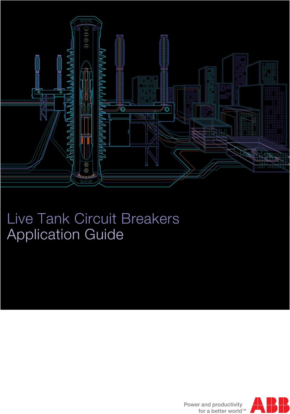
1 Live Tank Circuit Breakers Application Guide
2 Edited by ABB AB High Voltage Products Department: Marketing & Sales Text: Tomas Roininen, Carl Ejnar Sölver, Helge Nordli, Anne Bosma, Per Jonsson, Anders Alfredsson Layout, 3D and images: Mats Findell, Karl-Ivan Gustavsson SE LUDVIKA, Sweden 2 Application Guide ABB Circuit Breakers

3 Table of contents 1. Introduction What is a circuit breaker? Why do we need circuit breakers? Different types of switching Disconnecting and withdrawable circuit breakers Circuit switcher Environmental aspects Live tank circuit breaker designs and operating principles Historical development Main components Breaking unit Support insulator Operating mechanism Support structure Additional components Grading capacitors Preinsertion resistors Cabinets for central control SF 6 Interrupters SF 6 gas Principles of arc extinction Thermal regime Dielectric regime Earlier interrupter designs SF 6 puffer circuit breakers SF 6 self-blast circuit breakers Configuration of the moving contacts Operating mechanisms General Spring-operated mechanism Motor Drive Pneumatic-operated mechanism Hydraulic-operated mechanism Hydraulic spring-operated mechanism Other types of operating mechanisms Current switching and network stresses Short-circuit currents Standardized time constant and asymmetry Peak withstand current Terminal faults Transient Recovery Voltage (TRV) in single-phase networks TRV in three-phase networks Short-line faults Initial Transient Recovery Voltage (ITRV) Out-of-phase conditions Switching of capacitive currents De-energizing of capacitive loads 47 ABB Circuit Breakers Application Guide 3

4 Table of contents Recovery voltage Energizing of capacitor banks Inductive load switching Switching of shunt reactors Current chopping and resulting overvoltages Reignitions Overvoltages and overvoltage limitation Switching of no-load transformers Mechanical stresses and environmental effects Mechanical loads Static loads Dead weight Static terminal load Ice load Wind load Dynamic loads Dynamic loads due to operation Dynamic current loads Seismic load Measures to increase seismic withstand levels Combination of loads Influence of extreme ambient temperatures Gas properties Effect of ambient temperature Moisture content in SF 6 gas Sound effects of circuit breaker operation Standards Sound level as function of distance Thermal stresses Thermal limits Derating of rated current due to temperature Temperature rise test Temperature rise at current overload Influence of site altitude Insulation requirements Insulation co-ordination Overvoltages Short-duration power frequency voltage Lightning impulse Chopped impulse Switching impulse Insulation levels Dielectric tests on circuit breakers General Combined voltage test Other voltage tests 85 4 Application Guide ABB Circuit Breakers

5 RIV (Radio Interference Voltage) tests Partial discharge test Pollution test Tests on low-voltage circuits Atmospheric correction factor Installation at high altitudes Environmental effects and insulator shapes Creepage distance and pollution Environmental classes according to IEC Environmental classes according to IEEE Clearances in air Insulating material Application Transmission line circuit breakers Faults on overhead lines Switching of no-load transmission lines Voltage factor Line charging current Reclosing Shunt compensated transmission lines Series compensated transmission lines Classification Power transformer circuit breakers Asymmetry and d.c. time constant No-load switching conditions Synchronization Classification Capacitor/filter circuit breakers Recovery voltage and voltage factors Inrush current Rating and classification Shunt reactor circuit breakers Operating conditions Reignitions Elimination of reignitions Shunt reactor switching tests Classification Bus couplers Special applications Railway applications Railway applications with a power frequency less than 50 Hz Series capacitor by-pass switches HVDC filters SVC (Static Var Compensator) Instrument transformers and relays in combination 107 with live tank circuit breakers 7.8 Controlled switching 108 ABB Circuit Breakers Application Guide 5

6 Table of contents 8. Standards and tests Standards IEC Time definitions according to IEC ANSI/IEEE Circuit breaker testing Type tests Dielectric tests Radio Interference Voltage (RIV) tests Temperature rise tests Measurement of the resistance of the main circuit Short-time withstand current and peak withstand current tests Mechanical and environmental tests Mechanical operation test at ambient temperature Low and high temperatures tests/tightness tests High temperature test Humidity tests Ice tests Static terminal load test Making and breaking tests Preparation for tests Single-phase/three-phase testing Unit test/full pole test Direct tests Synthetic testing Summary of test duties Terminal fault Short-line fault Out-of-phase making and breaking tests Capacitive current switching Shunt reactor current switching tests Routine tests Test reports Type test reports Type test reports of independent laboratories STL organization SATS organization Reliability, maintenance and life cycle costs Failure statistics Electrical and mechanical life Maintenance Condition monitoring Life cycle costs Environmental aspects Selection of circuit breakers Application Guide ABB Circuit Breakers

7 Scope This document gives background information for selection of the best possible circuit breaker solution for each particular application. The guide addresses utility, consultant and project engineers who specify and apply high-voltage circuit breakers. The guide addresses live tank circuit breakers in general for voltages up to 800 kv. The most usual requirements on a circuit breaker are mentioned, such as the capabilities to handle network stresses, insulation levels, mechanical forces and ambient conditions. The construction of circuit breaker poles and operating mechanisms will be mentioned only briefly since these parts are described in ABB Buyer s Guide for Live Tank Circuit Breakers. ABB Circuit Breakers Application Guide 7

8 1. Introduction 1.1 What is a circuit breaker? A circuit breaker is an apparatus in electrical systems that has the capability to, in the shortest possible time, switch from being an ideal conductor to an ideal insulator and vice versa. Furthermore, the circuit breaker should be able to fulfill the following requirements: 1. In the stationary closed position, conduct its rated current without producing impermissible heat rise in any of its components. 2. In its stationary positions, open as well as closed, the circuit breaker must be able to withstand any type of overvoltages within its rating. 3. The circuit breaker shall, at its rated voltage, be able to make and break any possible current within its rating, without becoming unsuitable for further operation. The requirements on live tank circuit breakers may be as high as 80 ka current interrupting capability and 800 kv rated voltage. In addition to live tank circuit breakers, there are also other constructions of the circuit breaker poles (dead tank, GIS). In earlier times, oil and compressed air were typical insulating and extinguishing medium. Nowadays they are almost entirely replaced by SF 6 gas for economical and practical reasons, and also due to increased demands for higher ratings. There are different types of operating mechanisms, e.g. spring-, hydraulic- and pneumatic-operated mechanisms, and recently digitally-controlled motors have come into use. Figure 1.1 Circuit breaker for 145 kv Figure 1.2 Circuit breaker for 420 kv 8 Application Guide ABB Circuit Breakers

9 1.2 Why do we need circuit breakers? The circuit breaker is a crucial component in the substation, where it is used for coupling of busbars, transformers, transmission lines, etc. The most important task of a circuit breaker is to interrupt fault currents and thus protect electric and electronic equipment. The interruption and the subsequent reconnection should be carried out in such a way that normal operation of the network is quickly restored, in order to maintain system stability. In addition to the protective function, the circuit breakers are also applied for intentional switching such as energizing and de-energizing of shunt reactors and capacitor banks. For maintenance or repair of electrical equipment and transmission lines, the circuit breakers, together with the disconnectors, earthing switches or disconnecting circuit breakers with built-in disconnecting function, will ensure personnel safety. 1.3 Different types of switching The requirement to switch any current within the circuit breaker s rating includes different making and breaking conditions: Terminal faults, short-circuits in the vicinity of or near the circuit breaker. Short-line faults, short-circuits to ground along the transmission line within a few kilometers of the circuit breaker. Out-of-phase conditions at which different parts of the network are out of synchronism. Intentional switching of capacitor banks, shunt reactor banks, no-load transformers, no-load lines and cables. In this connection controlled switching ought to be mentioned. This is described in ABB Controlled Switching, Buyer s and Application Guide. The different switching conditions will be explained in Section 3, Current switching and network stresses. 1.4 Disconnecting and withdrawable circuit breakers It has been mentioned that the circuit breaker is an important element in the system, either as a stand-alone circuit breaker in a conventional substation or as an integrated part of a compact switchgear assembly. The modern solutions with Disconnecting Circuit Breakers (DCB) and Withdrawable Circuit Breakers (WCB) make it possible to develop new types of switchgear constructions. The purpose of the compact switchgear assembly is to simplify the switchgear and at the same time to improve the reliability of the system. ABB Circuit Breakers Application Guide 9

10 1. Introduction The different types of compact switchgears have one thing in common elimination of the conventional disconnectors in the system. Disconnectors have basically the same failure rate as circuit breakers, but need more frequent maintenance. The DCB is a circuit breaker that satisfies the requirements for a circuit breaker as well as a disconnector. This is described in IEC Ratings for current and voltage are the same as for a circuit breaker, while the insulating levels comply with those for disconnectors. Disconnecting circuit breakers are normally combined with remotely-operated earthing switches and interlocking systems to provide increased safety. A DCB for rated voltage 145 kv is shown in Figure 1.3. In the WCB, the circuit breaker poles are mounted on a movable trolley and provided with additional contacts for the disconnector function. The movement of the trolley replaces the close/open function of the conventional disconnectors. See Figure 1.4. A WCB can be extended with a complete gantry and busbars. It is even possible to equip the WCB with current transformers or earthing switches. Availability studies have shown that in substations with DCB or WCB, the availability is considerably improved over that of conventional solutions. In addition to the low failure rate and long periods between maintenance, another advantage is the substantial reduction in space. Figure 1.3 Disconnecting Circuit Breaker (DCB) for 145 kv. The earthing switch is painted in red and yellow. Figure 1.4 Withdrawable Circuit Breaker (WCB) for 145 kv with busbars and gantry. 10 Application Guide ABB Circuit Breakers

11 1.5 Circuit switcher The circuit switcher is a lighter economy variant of the live tank circuit breaker. The construction is similar and it can be applied for interruption of short-circuit currents, protection and switching of capacitor- and reactor-banks, transformers, lines and cables in accordance with IEC and IEEE/ANSI standards. The fault clearing rating is somewhat lower than that of the corresponding circuit breaker, and the operating times are longer. IEEE C specifies the requirements for circuit switches. 1.6 Environmental aspects Circuit breakers are installed in all kinds of environments and must be able to withstand and operate in any type of climatic conditions, such as extreme high and low temperatures, high humidity, ice loads and high wind velocities. Other important requirements are the capability to withstand seismic activity and to maintain correct function in areas with high pollution as well as in installations at high altitudes. ABB Circuit Breakers Application Guide 11

12 2. Live tank circuit breaker designs and operating principles 2.1 Historical development The air blast circuit breakers, which used compressed air as the extinguishing medium, had the advantage of high interrupting capability and short interruption times. However, the breaking units (interrupters) had limited dielectric withstand capability and, as can be seen in Figure 2.1, a circuit breaker for 420 kv needed up to 10 breaking elements in series per phase. The arc extinction required high air pressure, around 2 MPa, which meant that the risk of leakage was high. Installation, maintenance and repair were costly. Air blast Oil SF 6 gas Figure 2.1 The historical development of ABB live tank circuit breakers Introduction of the minimum oil circuit breakers around 1970 was a big step forward. The number of breaking units was reduced; a circuit breaker for 420 kv needed only four interrupters in series per phase. The demand of energy for operation was relatively low, and spring-charged mechanisms could be used. Both the minimum oil circuit breaker and the spring mechanisms are practically unaffected by the ambient temperature. Another great advantage is that all maintenance, even opening of the breaking units, can be carried out outdoors. However, although the maintenance is relatively simple, certain switching operations (e.g. switching of small inductive currents) require rather frequent maintenance. SF 6 gas circuit breakers are superior to these earlier technologies as they require substantially less maintenance. Furthermore, the numbers of breaking units are reduced. Up to 300 kv one interrupter per phase is used, and at 550 kv only two interrupters are required. All ABB SF 6 live tank circuit breakers can be operated with springcharged mechanisms, so that the energy demand for operation is now even lower for certain SF 6 circuit breakers than for the corresponding minimum oil circuit breaker. The operating mechanisms have developed correspondingly. Earlier pneumatic- and hydraulic- operated mechanisms were typical, but there is a general trend towards spring-operated mechanisms. 12 Application Guide ABB Circuit Breakers

13 2.2 Main components Live tank circuit breakers consist of four main components: One or more breaking units (interrupters) Support insulator One or more operating mechanisms Support structure (stand) The figures below shows the different parts of SF 6 circuit breakers. Figure 2.2. Three-pole operated circuit breaker with one interrupter per pole. Figure 2.3. One pole of a single-pole operated circuit breaker with two interrupters per pole. Circuit breaker components 1. Breaking unit 5. Trip mechanism 9. Grading capacitor (if required) 2. Support insulator 6. Gas supervision (on opposite side) 10. Preinsertion resistor (PIR) (if required) 3. Support structure 7. Pullrod with protective tube 11. Primary terminals 4. Operating mechanism 8. Position indicator ABB Circuit Breakers Application Guide 13
 10. Preinsertion resistor (PIR) (if required) 3. Support structure 7. Pullrod with protective tube 11. Primary terminals 4.")
14 2. Live tank circuit breaker designs and operating principles Breaking unit The insulating housing is made of porcelain or composite material and is filled with pressurized SF 6 gas. The breaking unit is subjected to potential, i.e. it is live, hence the term live tank circuit breaker. One circuit breaker pole can even consist of two or more breaking units in series. The number of breaking units is dependent on the system voltage and the requirements on interrupting capability. The function of the extinction chamber is described under Principles of arc extinction Support insulator The main function of the support insulator is to ensure sufficient insulation from the HV-terminals and the breaking unit(s) to ground. The support insulator is a hollow housing made of porcelain or composite material and contains SF 6 gas at the same pressure as the gas in the breaking units; the support insulator and the breaking unit(s) have a common gas atmosphere. The insulated pull rod, (also called operating insulator) which is part of the linkage system between the operating mechanism and the main contacts, is mounted inside the support insulator Operating mechanism The operating mechanism, together with the trip spring, stores the necessary energy for the closing and opening operation of the circuit breaker. Located at ground potential, the operating mechanism also includes secondary wiring, which acts as an interface to a network s control and protection system Support structure There are two versions of support structures (or support stand) for live tank circuit breakers: Three-column supports, i.e. each circuit breaker pole is mounted on its individual support. Pole-beam support, i.e. the three poles mounted on one common beam with two support legs. The supports are usually made of hot-dip galvanized steel. 14 Application Guide ABB Circuit Breakers
 to ground.")
15 2.3 Additional components Grading capacitors For circuit breakers with two or more breaking units in series, the voltage (rated voltage as well as transient switching and lightning overvoltages) will usually not be evenly distributed across the interrupters. In order to avoid high voltage stresses across one of the breaking units, capacitors are often mounted in parallel with the interrupters. The capacitance is usually on the order of 900 1,600 pf per breaking unit. The performance of circuit breakers is gradually improving, and nowadays grading capacitors are generally not needed at rated voltages up to 420 kv. The ABB circuit breaker of the HPL type has recently been verified by type tests to handle 550 kv without grading capacitors. This offers several advantages: easier transport and installation; lower mass, which improves the seismic withstand capability; decreases in leakage currents; and a reduced risk of ferroresonance in nearby inductive voltage transformers Preinsertion resistors Preinsertion resistors on line circuit breakers are used occasionally at rated voltages kv and more often at kv. Their purpose is to reduce the voltage transients generated when a no-load transmission line is energized, or reenergized after a line fault. The resistors are operated by the same operating mechanism as the main contacts. Preinsertion resistors were previously sometimes used on circuit breakers for capacitor banks, reactor banks and transformers. For these applications, however, controlled switching is now widely used as a powerful means to reduce the switching transients. Modern SF 6 circuit breakers also have better switching properties than old circuit breaker types. This has generally made preinsertion resistors superfluous for these applications. New technologies may also eliminate the need for preinsertion resistors for line circuit breakers. In many cases controlled switching can replace the resistors and reduce the voltage transients to the same extent as, or even better than, resistors. See ABB Controlled Switching, Buyer s and Application Guide Cabinets for central control Circuit breakers for single-pole operation can be provided with cabinets for central control. These are convenient for local three-pole operation. In some cases one of the operating mechanism cabinets is expanded to handle integration of the functions of the central control cabinet. This solution is sometimes referred to as Master-slave or ICC, Integrated Control Cubicle. ABB Circuit Breakers Application Guide 15

16 2. Live tank circuit breaker designs and operating principles 2.4 SF 6 Interrupters SF 6 gas High-voltage circuit breakers with SF 6 gas as the insulation and quenching medium have been in use throughout the world for more than 30 years. This gas is particularly suitable because of its high dielectric strength and thermal conductivity Principles of arc extinction The current interruption process in a high-voltage circuit breaker is a complex matter due to simultaneous interaction of several phenomena. When the circuit breaker contacts separate, an electric arc will be established, and current will continue to flow through the arc. Interruption will take place at an instant when the alternating current reaches zero. When a circuit breaker is tripped in order to interrupt a short-circuit current, the contact parting can start anywhere in the current loop. After the contacts have parted mechanically, the current will flow between the contacts through an electric arc, which consists of a core of extremely hot gas with a temperature of 5,000 to 20,000 K. This column of gas is fully ionized (plasma) and has an electrical conductivity comparable to that of carbon. When the current approaches zero, the arc diameter will decrease, with the crosssection approximately proportional to the current. In the vicinity of zero passage of current, the gas has been cooled down to around 2,000 K and will no longer be ionized plasma, nor will it be electrically conducting. Two physical requirements (regimes) are involved: Thermal regime: The hot arc channel has to be cooled down to a temperature low enough that it ceases to be electrically conducting. Dielectric regime: After the arc extinction, the insulating medium between the contacts must withstand the rapidly-increasing recovery voltage. This recovery voltage has a transient component (transient recovery voltage, TRV) caused by the system when current is interrupted. If either of these two requirements is not met, the current will continue to flow for another half cycle, until the next current zero is reached. It is quite normal for a circuit breaker to interrupt the short-circuit current at the second or even third current zero after contact separation. 16 Application Guide ABB Circuit Breakers

17 a) Simplified equivalent circuit. b) Curves of short-circuit current i sc and recovery voltage u r t 1 = contact separation t 2 = arc extinction S = rate of rise of recovery voltage Figure 2.4 Stresses on the extinction chamber at interruption. (The arc voltage from contact separation to arc extinction is low and has been disregarded) Thermal regime The thermal regime is especially critical at short-line fault interruption (see Section 3). The circuit parameters directly affecting this regime are the rate of decrease of the current to be interrupted (di/dt) and the initial rate of rise of the transient recovery voltage (du/dt) immediately after current zero. The higher the values of either of these two parameters, the more severe the interruption. A high value of di/dt results in a hot arc with a large amount of stored energy at current zero, which makes interruption more difficult. High values of du/dt will result in an increase of the energy to the post-arc current. There exists a certain inertia in the electrical conductivity of the arc (see Figure 2.5). When the current approaches zero, there is still a certain amount of electrical conductivity left in the arc path. This gives rise to what is called a post-arc current with amplitude up to a few A. Whether or not the interruption is going to be successful is determined by a race between the cooling effect and the energy input in the arc path by the transient recovery voltage. When the scales of the energy balance tip in favor of the energy input, the circuit breaker will fail thermally. The thermal interruption regime for SF 6 circuit breakers corresponds to the period of time starting some µs before current zero, until extinguishing of the post arc current, a few µs after current zero. ABB Circuit Breakers Application Guide 17
 and the initial rate of rise of the transient recovery voltage (du/dt)")
18 2. Live tank circuit breaker designs and operating principles Figure 2.5 Current shape at interruption (the time scale is in the microsecond range) Dielectric regime When the circuit breaker has successfully passed the thermal regime, the transient recovery voltage (TRV) between the contacts rises rapidly and will reach a high value. For example, in a single-unit 245 kv circuit breaker the contact gap may be stressed by 400 kv or more 70 to 200 μs after the current zero. In the dielectric regime the extinguishing/isolating medium is longer electrically conducting, but it still has a much higher temperature than the ambient. This reduces the voltage withstand capacity of the contact gap. The stress on the circuit breaker depends on the rate-of-rise and the amplitude of the TRV. Figure 2.6 Dielectric interruption regime The withstand capability of the contact gap must always be higher than the transient recovery voltage, see Figure 2.6, otherwise a dielectric reignition will occur (dielectric failure). This requires an extremely high dielectric withstand capability of the gas, which is still rather hot and therefore has low density. 18 Application Guide ABB Circuit Breakers

19 2.4.3 Earlier interrupter designs The first circuit breakers applying SF 6 gas had the extinguishing chamber divided into two separate parts with different pressures (double-pressure circuit breaker), operating on the same principle as air-blast circuit breakers. Nowadays all highvoltage SF 6 circuit breakers have extinguishing chambers which apply puffer or self-blast principles SF 6 puffer circuit breakers In the SF 6 puffer, the gas pressure for the cooling blast is created during the opening stroke in a compression cylinder. In the opening operation, the compression of the gas will start at the same time as the contacts start their motion. The compressed gas is blown out through an insulating nozzle in which the arc is burning. Figure shows the function of a puffer interrupter. The insulating nozzle is normally made of PTFE. Figure Main components of the puffer interrupter. Red color indicates the current path through the closed interrupter. ABB Circuit Breakers Application Guide 19

20 2. Live tank circuit breaker designs and operating principles Contact parting Closed Main Arcing Arc Open Closing position extinction position A B C D E F Figure Function of a puffer interrupter: A. Closed position. The current is conducted through the main contacts. B. Separation of main contacts. The moving contacts have started to change position, the main contacts have parted. The current is commutated to the arcing contacts. Pressure is starting to build up in the puffer volume. C. After separation of the arcing contacts an arc is established between them. Pressure in the puffer volume continues to increase. D. Arc extinction. The current approaches zero and the cold gas from the puffer volume blasts up through the nozzle, cooling the arc and extinguishing it. E. The contacts are now fully open; the motion has been damped and stopped by the operating mechanism. F. During closing the contacts close and the puffer volume is refilled with cold gas, making it ready for the next opening operation. One important feature of the puffer design is the current-dependent build-up of extinguishing pressure. At a no-load operation (without arc) the maximum pressure in the puffer cylinder is typically twice the filling pressure. See the no-load curve in Figure Application Guide ABB Circuit Breakers

21 A heavy arc burning between the contacts blocks the gas flow through the nozzle. When the current decreases towards zero, the arc diameter also decreases, leaving more and more outlet area free for the flow of gas. A full gas flow is thus established at the current zero, resulting in maximum cooling when needed. The blocking of the nozzle (nozzle clogging) during the high current interval gives a further pressure build-up in the puffer cylinder that may be several times the maximum no-load pressure (see Figure 2.8). In other words: the decreasing puffer volume, nozzle clogging and heating of the gas by the arc interact to create a high pressure. The high pressure in the puffer requires a high operating force. The blast energy is therefore almost entirely supplied by the operating mechanism. Figure 2.8. Pressure in the puffer volume at no-load operation and during interruption of an asymmetrical short-circuit current of 40 ka In order to extinguish the arc, a certain blast pressure is required and is determined by the rate-of-change of current at current zero (di/dt) and the rate of rise of the recovery voltage immediately after current zero (du/dt) as described under ABB Circuit Breakers Application Guide 21
22 2. Live tank circuit breaker designs and operating principles SF 6 self-blast circuit breakers Service experience has shown that circuit breaker failures due to insufficient interrupting capacity are rare. The majority of the failures reported are of a mechanical nature, which is why efforts are made to improve the overall reliability of the operating mechanisms. Because of the fact that puffer circuit breakers require high operating energy, the manufacturers were forced to use pneumatic mechanisms, hydraulic mechanisms or high-energy spring mechanisms. In a normal puffer circuit breaker, the major part of the blast pressure is created with energy from the operating mechanism. The ideal situation would be to let the arc produce the blast pressure. In this way, the operating mechanism only needs to deliver energy necessary for the movement of the contact. However, this ideal situation cannot currently not be reached at higher voltages. Problems will arise when interrupting small currents, since there is only a limited amount of energy available for the pressure rise. For this reason a compromise has been reached: a self-blast circuit breaker with pre-compression. The self-blast principles represented a large step forward on the way to reducing the operating energy. The self-blast technology has several designations: auto-puffer, arc-assisted circuit breaker, thermal-assisted circuit breaker or simply self-blast circuit breaker. Because the blast pressure required for interruption of low currents and low current derivatives (see ) is moderate, a small pressure rise independent of the current is sufficient. For higher currents, the energy producing the blast pressure is taken from the arc through heating of the gas. Figure Main components of the self-blast interrupter. Red color indicates the current path through the closed interrupter. 22 Application Guide ABB Circuit Breakers
23 Contact parting Closed Main Arcing Arc Open Closing position extinction position A B C D E F Figure Self-blast SF 6 interrupter with pre-compression. The figure shows high current interruption. A. Closed position. The current is conducted through the main contacts. B. Separation of main contacts. The moving contact has started to change position, the main contacts have parted. Pressure is starting to build up in the puffer and self-blast volumes. The current is commutated to the arcing contacts. C. After separation of the arcing contacts an arc is established between them. Heat from the arc generates pressure in the self-blast volume, the valve closes when the pressure is higher than in the puffer volume.* D. Arc extinction. The current approaches zero and the gas from the self-blast volume blasts up through the nozzle, cooling the arc and extinguishing it. Excessive pressure in the puffer volume is released through the pressure relief valve. E. The contacts are now fully open; the motion has been damped and stopped by the operating mechanism. F. During closing the contacts close and the puffer volume is refilled with cold gas, making it ready for the next opening operation. * At low breaking current the pressure generated by the arc will not be sufficient to close the valve. The self-blast interrupter will then operate as a puffer interrupter. ABB Circuit Breakers Application Guide 23
24 2. Live tank circuit breaker designs and operating principles As can be seen in Figure 2.9.1, the extinction chamber is divided into two sections: the self-blast volume and the puffer volume. The two sections are separated by the self-blast valve. When high-fault currents are interrupted, the pressure in the self-blast volume generated by the arc will be so high that the valve will close, preventing the gas from escaping into the puffer volume. Instead, the pressurized gas will flow through the nozzle and extinguish the arc. At lower currents, typically a few ka, the arc will not have sufficient energy to generate a pressure high enough to close the valve and the interrupter will function as a puffer interrupter. The pressure in the puffer volume is relatively independent of the current whether the circuit breaker operates as a self-blast interrupter or as a puffer interrupter. It is limited to a moderate level by means of a spring-loaded valve (overpressure valve), which means that the compression energy required from the operating mechanism is limited. Figure 2.10 shows how the energy from the operating mechanism is used. Compared with a conventional puffer circuit breaker of the same rating, the energy requirements of the operating mechanism can be reduced to 50% or less. Figure 2.10 Utilization of operating energy at a breaking operation 24 Application Guide ABB Circuit Breakers
25 2.4.6 Configuration of the moving contacts For the self-blast circuit breakers, several different principles of moving contact configurations exist. Their purpose is to further decrease the amount of energy needed for the operation of the circuit breaker. The single-motion design dominates the market today. This is the simplest type of design, utilizing one moving set of arcing and main contacts. The double-motion design uses a linkage system to move both the puffer with the lower contact system, and the upper arcing contact, in different directions. This means that the speed requirement from the operating mechanism is drastically reduced, since the contact speed will be the relative speed between the upper and lower contacts. The main benefit of the double-motion arrangement is the minimized energy need for the contact movement due to lower speed demands. This is visualized by the equation for kinetic energy: The triple-motion design is based on the double-motion design, but moves the upper shield at a different speed than that of the upper arcing contact to optimize the distribution of the electrical fields and get a better dielectrical performance. Figure 2.11 Double motion design ABB Circuit Breakers Application Guide 25
26 2. Live tank circuit breaker designs and operating principles 2.5 Operating mechanisms General The main requirement of the operating mechanism is to open and close the contacts of the circuit breaker within a specified time. The operating mechanism shall provide the following consecutive functions: Charging and storing of energy Release of energy Transmission of energy Operation of the contacts In addition, an operating mechanism shall provide control and signaling interface to a network s control and protection system. Figures 2.2 and 2.3 show the location of the operating mechanism. A requirement common to most circuit breakers, regardless of the type of operating mechanisms, is to carry out an open-close-open (O s - CO) sequence with no external power supply to the operating mechanism. The circuit breaker shall, after a closing operation, always be able to trip immediately without intentional time delay. For circuit breakers intended for rapid auto-reclosing, the operating duty cycle in accordance with IEC is: O 0.3 s CO 3 min - CO The time of 3 min is the time needed for the operating mechanism to restore its power after a O 0.3 s - CO. Modern spring and hydraulic operating mechanisms do not need 3 min to restore their power, as an alternative IEC specifies that the time values 15 s. or 1 min. can also be used. The dead time of 0.3 s is based on the recovery time of the air surrounding an external arc in the system (i.e. a short-circuit). Sometimes the operating sequence CO - 15 s - CO is specified. 26 Application Guide ABB Circuit Breakers
27 2.5.2 Spring-operated mechanism In the spring mechanism, the energy for open and close operation is stored in springs. When the mechanism s control system receives an open or close command, the energy stored in the spring will be released and transmitted through a system of levers and links and the contacts will move to the open or closed position. In most designs the closing spring has two tasks: to close the contacts, and at the same time to charge the opening spring (or springs). Thus the criteria stated above are fulfilled; the circuit breaker in closed position is always ready to trip. After the O s - CO operation, the closing spring will be recharged by an electric motor, a procedure that lasts seconds. The circuit breaker will then be ready for another CO operation. One example of a spring mechanism is shown in Figure This type of mechanism has a set of parallel helical wound springs with linear motion. The electric motor charges the springs via an endless chain. When the closing latch is released, the energy stored in the springs is transmitted via a rotating cam disc and a system of levers and links to the circuit breaker pole or poles. The trip spring is in this case located outside the operating mechanism. Instead of helical springs, clock springs may be applied. The function is the same as for the helical springs described above. Figure 2.13 shows a system with clock spring for closing operation. The advantage of the spring-operated mechanism is that the system is purely mechanical; there is no risk of leakage of oil or gas, which could jeopardize the reliability. A well-balanced latching system provides stable operating times. Furthermore, the spring system is less sensitive to variations in temperature than pneumatic or hydraulic mechanisms are. This ensures stability even at extreme temperatures. The spring mechanism has fewer components than hydraulic and pneumatic mechanisms, which improves its reliability. ABB Circuit Breakers Application Guide 27
28 2. Live tank circuit breaker designs and operating principles Figure 2.12 Spring operating mechanism with helical wound springs. Trip and close springs in charged position. ABB type BLG. 1. Link gear 5. Closing damper 2. Trip spring 6. Tripping latch with coil 3. Closing latch with coil 7. Opening damper 4. Motor 8. Close springs 28 Application Guide ABB Circuit Breakers
29 Figure 2.13 Spring operating mechanism with clock spring. ABB type BLK. 1. Trip spring 5. Closing latch with coil 2. Link gear 6. Motor 3. Close spring 7. Opening damper 4. Tripping latch with coil ABB Circuit Breakers Application Guide 29
30 2. Live tank circuit breaker designs and operating principles Motor Drive One of the most recently-developed operating mechanisms is the electrical motor drive. The motor drive uses a servomotor to perform a smooth and silent operation of the circuit breaker. The operation is actively controlled by a sensor which continuously reads the position of the motor and adjusts the motor current to obtain an optimal travel curve. The energy is stored in a capacitor bank and can be delivered instantaneously to the converter, which transforms dc from the capacitors and feeds the motor with regulated ac. The major advantage of the motor drive is the minimized mechanical system, which reduces the service need to a minimum and makes the technology ideal for applications with frequent operation AC DC Trip Close Status signals Motor Position sensor Figure 2.14 Block diagram showing function of the Motor Drive 1. Charger unit that converts supply voltage and feeds the capacitors and internal electronics. 2. Capacitor unit stores the energy for operation. 3. The converter unit transforms dc from the capacitors to ac for the motor. 4. Servomotor that delivers the force to move the contacts, integrated position sensor gives information to the control unit. 5. The I/O unit takes care of signaling between the station control system and the operating mechanism. 6. Control unit that controls and regulates the motion of the contacts. The interlock functions are also handled by this module. 7. Link gear that transforms rotary movement to linear movement. 30 Application Guide ABB Circuit Breakers
31 2.5.4 Pneumatic-operated mechanism The pneumatic-operated mechanism uses compressed air as energy storage, and pneumatic cylinders for operation. Solenoid valves allow the compressed air into the actuating cylinder for closing or for opening. The compressed-air tank is replenished by a compressor unit. The use of pneumatic operating mechanisms is decreasing. Due to the high operating pressure, there is always a risk of leakage of air, particularly at low temperatures. There is also a risk of corrosion due to humidity in the compressed air Hydraulic-operated mechanism The hydraulic mechanism usually has one operating cylinder with a differential piston. The oil is pressurized by a gas cushion in an accumulator, and the operating cylinder is controlled by a main valve. The hydraulic mechanism has the advantages of high energy and silent operation. However, there are also some disadvantages. There are several critical components which require specialized production facilities. The risk of leakage cannot be neglected as the operating pressure is in the range of MPa ( bar). It is necessary not only to check the pressure as such but also to supervise the oil level in the accumulator or, in other words, the volume of the gas cushion. Large variations in temperature lead to variations in operating time. Until recently several manufacturers used hydraulic mechanisms for their SF 6 circuit breakers. However, with the introduction of self-blast circuit breakers, the requirement of high energy for operation is decreasing and the hydraulic mechanisms are losing ground to spring-operated mechanisms Hydraulic spring-operated mechanism The hydraulic spring-operated mechanism is an operating mechanism combining hydraulics and springs. Energy is stored in a spring set, that is tensioned hydraulically. A differential piston, powered by oil that is pressurized by the spring package, is used to operate the circuit breaker during opening and closing. Figure 2.15 Hydraulic spring-operated mechanism. ABB type HMB ABB Circuit Breakers Application Guide 31
32 2. Live tank circuit breaker designs and operating principles Other types of operating mechanisms In addition to the types of operating mechanisms mentioned above, there are other variants, e.g. a design which basically applies the same technology as the pneumatic mechanisms but with SF 6 gas instead of air. Another design is the magnetic actuator mechanism, which is applied only for certain medium-voltage circuit breakers. 32 Application Guide ABB Circuit Breakers
33 3. Current switching and network stresses 3.1 Short-circuit currents A circuit breaker should be able to interrupt both symmetrical and asymmetrical short-circuit currents. Asymmetrical short-circuit currents consist of a symmetrical component superimposed on a dc component. The dc component will decrease with time. Consider a part of a typical network as shown in Figure 3.1. At normal operation, load currents of the magnitude of approximately 100 amperes will flow in the different branches. If a short-circuit occurs somewhere in the system, the currents will change dramatically into short-circuit currents that are two or three orders of magnitude higher than the load currents. Figure 3.1 Network with short-circuit Figure 3.2 Single-phase equivalent network With a short-circuit in point A, the system may, in a simple approximation, be represented by a single-phase equivalent network as shown in Figure 3.2. The inductance L may be obtained from the short-circuit power (fault level) S k of the network as: In this equation ω is the angular frequency (2πf ) and U is the system voltage (phase-to-phase). The resistance R represents the losses in the network. It is normally low compared to the inductive reactance X = ωl, perhaps 5 to 10%. The voltage source u in Figure 3.2 is the phase-to-neutral voltage. ABB Circuit Breakers Application Guide 33
34 3. Current switching and network stresses Figure 3.3 shows the voltages and currents associated with a short-circuit at point A. Up to the short-circuit instant - which has been chosen arbitrarily - the current is low and has been shown as a zero line in the figure. After the short-circuit has occurred, the current will approach a steady state symmetrical value i sym. The phase angle will be almost 90 lagging, since the circuit is more or less purely inductive. Since the current in an inductive circuit can not be discontinuous at the short-circuit instant, the total short-circuit current (i total ) will consist of a symmetrical part i sym and dc component i dc : Figure 3.3 Current and voltage at short-circuit The initial magnitude I dc of the dc component will be equal to the instantaneous value of the symmetrical short-circuit current i sym at the short-circuit instant and has the opposite polarity. In this way the transition from load to short-circuit current will be continuous. The dc component will follow an exponentially damped curve and can be written as: where: t time from initiation of the short-circuit τ the time constant of the network τ is determined by the losses of the circuit, τ = L/R and is of the order of ms in typical networks. 34 Application Guide ABB Circuit Breakers
35 3.1.1 Standardized time constant and asymmetry Both IEC and IEEE use a standard value of the time constant, τ = 45 ms. This value covers most cases. Sometimes specification of the time constant is replaced by specification of the X/R (= ωl/r) ratio of the network. This value depends on the network frequency. The standard time constant 45 ms corresponds to X/R = 14 at 50 Hz, and X/R = 17 at 60 Hz. Normally the amount of asymmetry of the current at a certain instant of time is given by stating the dc component as a percentage of the (peak value of) symmetrical current. The dc component used for type testing of a circuit breaker is determined as follows (refer to IEC ): For a circuit-breaker that is intended to be tripped solely by means of auxiliary power (e.g. by giving an impulse to a device that releases the circuit-breaker for operation), the percentage dc component shall correspond to a time interval equal to the minimum opening time T op of the circuit-breaker plus one half-cycle of rated frequency T r. (See also Figure 3.4). Example: What is the dc component required for a circuit breaker having a minimum opening time of 18 ms, used on a 50 Hz system with a time constant of 45 ms? Answer: Minimum opening time: T op = 18 ms Rated frequency 50 Hz gives T r = 10 ms T op + T r = = 28 ms leads to a dc component of 54% (see Figure 3.4) For rated frequency 60 Hz (T r = 8.3 ms) the dc component is 56%. The r.m.s. value of the asymmetrical current (also known as the total current) can be determined using the following formula: where: p the dc component in p.u. I sym the rms. value of the symmetrical part ABB Circuit Breakers Application Guide 35
36 3. Current switching and network stresses Sometimes it is necessary to use larger values for the time constant than 45 ms. For example, this can be the case close to large generator units, where the network resistance is low. For such situations IEC specifies alternative, special case time constants : 120 ms for rated voltages up to and including 52 kv 60 ms for rated voltages from 72.5 kv up to and including 420 kv 75 ms for rated voltages 550 kv and above In order to minimize special testing, etc. it is preferable that these values are applied when the standard value 45 ms cannot be used. Percent dc Time (ms) Figure 3.4 Percentage dc component in relation to time (from IEC ) Peak withstand current Due to the dc component, the short-circuit current will be asymmetrical for a certain time after the initiation of the short-circuit. On the one hand, this has to be considered when designing circuit breakers which will be called upon to interrupt such currents. On the other hand, this is important for all the components in the network, since the mechanical stresses due to the currents will be most severe at the maximum peak of the asymmetrical short-circuit current. The highest possible current peak will occur if the short-circuit is initiated at the zero passage of the voltage. The probability of this happening in the network is low, but needs to be considered. Lightning strikes occur at random time instants, and can therefore in the worst case initiate short-circuits when the instantaneous voltage in the system is zero. In contrast, any short-circuits caused by the system voltage itself, e.g. in the case of damaged or polluted insulation systems, will mainly occur close to the peak value of the voltage in the system. 36 Application Guide ABB Circuit Breakers
High-Voltage Circuit-Breakers 3AP1/2 72.5 kv up to 550 kv. Power Transmission and Distribution
 High-Voltage Circuit-Breakers AP/ 7.5 kv up to 550 kv Power Transmission and Distribution The AP/ High-Voltage Circuit-Breakers Now Applicable for 550 kv Decades of our experience in high-voltage switching
www.siemens.com/energy High Voltage Circuit Breakers 3AP Type 72.5 kv to 800 kv Answers for energy.
 s www.siemens.com/energy High Voltage Circuit Breakers AP Type 7.5 kv to 800 kv Answers for energy. The AP High Voltage Circuit Breakers Available up to 800 kv Decades of our experience in high voltage
Circuit Breaker LTB D with Motor Drive. Motor Drive. ABB PP/H/HV - Page 1. Ed 2006-04
 Circuit Breaker LTB D with Motor Drive Motor Drive ABB PP/H/HV - Page 1 Ed 2006-04 Technology Traditional technology Traditional spring operating mechanism: Closing mechanism ABB PP/H/HV - Page 2 Tripping
SF 6 Gas Insulated Switchgear Type SDF for 170 kv
 Three Phase Encapsulated Type SF 6 Gas Insulated Switchgear Type SDF for 170 kv 06B1-E-0001 With Trustworthy Technology, Structure Fuji Electric as a manufacturer of comprehensive substation equipment
High-Voltage Compact Switchgear 3AP1 DTC for 145 kv and 245 kv
 High-Voltage Compact Switchgear AP1 DTC for 1 kv and kv Answers for energy. The AP1 DTC Complying with our Customers demands Experience you can rely on - at anytime, anywhere Decades of experience in high-voltage
Unified requirements for systems with voltages above 1 kv up to 15 kv
 (1991) (Rev.1 May 2001) (Rev.2 July 2003) (Rev.3 Feb 2015) Unified requirements for systems with voltages above 1 kv up to 15 kv 1. General 1.1 Field of application The following requirements apply to
Instrument Transformers Application Guide
 Instrument Transformers Application Guide Edited by ABB AB High Voltage Products Department: Marketing & Sales Text: Knut Sjövall, ABB Layout, 3D and images: Mats Findell, ABB SE-771 80 LUDVIKA, Sweden
Digital Energy ITI. Instrument Transformer Basic Technical Information and Application
 g Digital Energy ITI Instrument Transformer Basic Technical Information and Application Table of Contents DEFINITIONS AND FUNCTIONS CONSTRUCTION FEATURES MAGNETIC CIRCUITS RATING AND RATIO CURRENT TRANSFORMER
ABB s Disconnecting Circuit Breakers Higher substation availability and lower environmental impact
 ABB s Disconnecting Circuit Breakers Higher substation availability and lower environmental impact Authors Carl Ejnar Sölver, ABB High Voltage Products Rasmus Larsson, ABB High Voltage Products 2 ABB ABB
Fundamentals of Modern Electrical Substations Part 1: Mission of Electrical Substations and their Main Components
 Fundamentals of Modern Electrical Substations Part 1: Mission of Electrical Substations and their Main Components Course No: E02-010 Credit: 2 PDH Boris Shvartsberg, Ph.D., P.E., P.M.P. Continuing Education
Line Reactors and AC Drives
 Line Reactors and AC Drives Rockwell Automation Mequon Wisconsin Quite often, line and load reactors are installed on AC drives without a solid understanding of why or what the positive and negative consequences
The Importance of the X/R Ratio in Low-Voltage Short Circuit Studies
 The Importance of the X/R Ratio in Low-Voltage Short Circuit Studies DATE: November 17, 1999 REVISION: AUTHOR: John Merrell Introduction In some short circuit studies, the X/R ratio is ignored when comparing
AutoLink Three-Phase Sectionalizer Specifications. Scope. General. Applicable Standards. Operating principle
 Scope This specification stipulates the minimum requirements for mechanically linked three-phase electronic sectionalizers, for use on outdoor medium voltage overhead lines of 15, 27, and 38 kv. Electronic
Dead Tank Circuit Breaker 72PM40-C Proven reliability through common platforms
 Dead Tank Circuit Breaker 72PM40-C Proven reliability through common platforms ABB innovations for changing demands ABB (www.abb.com) is a leader in power and automation technologies that enables utility
SWITCHGEAR PROTECTION
 LECTURE NOTES ON SWITCHGEAR PROTECTION IV B. Tech I semester (JNTUH-R09) Mr. P SHIVAKUMAR Assistant Professor ELECTRICAL AND ELECTRONICS ENGINEERING INSTITUTE OF AERONAUTICAL ENGINEERING DUNDIGAL, HYDERABAD
MV, HV AND EHV SWITCHGEAR TESTING & COMMISSIONING
 Training Title MV, HV AND EHV SWITCHGEAR TESTING & COMMISSIONING Training Duration 5 days Training Date MV, HV and EHV Switchgear Testing & Commissioning 5 20 24 Apr $3,750 Dubai, UAE In any of the 5 star
The Intelligent AX1 Switchgear for Medium Voltage
 The Intelligent AX1 Switchgear for Medium Voltage Leif Lundin, Manager of Research and Development, Division Medium Voltage and Compact Substations, ABB Distribution, Sweden Abstract The newly launched
DIMENSIONING OF CURRENT TRANSFORMERS FOR PROTECTON APPLICATION
 ÿþ üûúùø öõöôùóùõò CT Dimensioning DIMENSIONING OF CURRENT TRANSFORMERS FOR PROTECTON APPLICATION Application note GER3973 1 CT Dimensioning ÿþ üûúùø öõöôùóùõò GER-3973 Application note ÿþ üûúùø öõöôùóùõò
HVDC 2000 a new generation of high-voltage DC converter stations
 HVDC 2000 a new generation of high-voltage DC converter stations Improved performance and robustness, shorter lead times and faster delivery, plus reduced maintenance needs, were the development goals
Transformers. Special transformers Reactors products
 Transformers Special transformers Reactors products Reactors Custom designed, custom built ABB Oy Transformers has extensive experience and numerous references from different reactor applications, having
Proven vacuum switching technology from Siemens meets all requirements placed on circuit-breakers and contactors in medium-voltage switchgear up to
 Proven vacuum switching technology from Siemens meets all requirements placed on circuit-breakers and contactors in medium-voltage switchgear up to 40.5 kv. 2 Contents Overview of medium-voltage components
3AH5 Vacuum Circuit-Breakers. Answers for energy. Medium-Voltage Equipment Selection and Ordering Data. Catalog HG 11.05 2010
 Medium-Voltage Equipment Selection and Ordering Data Catalog HG 11.05 2010 Answers for energy. R-HG11-172.tif 2 Siemens HG 11.05 2010 Contents Contents Page 3AH5 Vacuum Circuit-Breakers Medium-Voltage
LIMITING SHORT-CIRCUIT CURRENTS IN MEDIUM-VOLTAGE APPLICATIONS
 LIMITING SHORT-CIRCUIT CURRENTS IN MEDIUM-VOLTAGE APPLICATIONS Terence Hazel Senior Member IEEE Schneider Electric 38050 Grenoble France Abstract The power requirements for large industrial sites is increasing.
UniGear ZS1. Medium voltage, arc proof, air insulated switchgear for primary distribution
 UniGear ZS1 Medium voltage, arc proof, air insulated switchgear for primary distribution UniGear ZS1: an innovative solution for all installation requirements ABB UniGear is medium voltage metal-clad,
IEC and IEEE Standards for High-Voltage Switchgear and Controlgear Present Situation and Future Evolution
 IEC and IEEE Standards for High-Voltage Switchgear and Controlgear Present Situation and Future Evolution Denis Dufournet Chairman IEC TC 17 & SC17A Fellow IEEE Senior Expert Areva T&D Mumbai, January,
Cahier technique no. 193
 Collection Technique... Cahier technique no. 193 MV breaking techniques S. Théoleyre "Cahiers Techniques" is a collection of documents intended for engineers and technicians, people in the industry who
Advantages of Fixed Circuit Breaker Switchgear
 Advantages of Fixed Circuit Breaker Switchgear by Lionel Mackay, EDF Energy, and Mike Adams, Schneider Electric Ltd Introduction The purpose of this paper is to review the advantages of fixed circuit breaker
Chapter 11. Inductors ISU EE. C.Y. Lee
 Chapter 11 Inductors Objectives Describe the basic structure and characteristics of an inductor Discuss various types of inductors Analyze series inductors Analyze parallel inductors Analyze inductive
DC TRANSMISSION BASED ON VOLTAGE SOURCE CONVERTERS
 DC TRANSMISSION BASED ON VOLTAGE SOURCE CONVERTERS by Gunnar Asplund, Kjell Eriksson, Hongbo Jiang, Johan Lindberg, Rolf Pålsson, Kjell Svensson ABB Power Systems AB Sweden SUMMARY Voltage Source Converters
Primary-Side Transformer Protection
 Primary-Side Transformer Protection Peter J. Meyer, S&C Electric Company, Chicago, Illinois Presented at the Doble Life of a Transformer Seminar; Laguna Beach, California February 21 25, 2005 INTRODUCTION
2a. IEM Indoor Metal Clad Medium Voltage Switchgear 15KV 16346-1. 2a. Section 16346 INDOOR METAL CLAD MEDIUM VOLTAGE SWTICHGEAR (Std.
 2a. IEM Indoor Metal Clad Medium Voltage Switchgear 15KV 16346-1 2a. Section 16346 INDOOR METAL CLAD MEDIUM VOLTAGE SWTICHGEAR (Std. Relays) Part 1 General 1.1 CONDITIONS AND REQUIREMENTS: A. Refer to
Why and How we Use Capacity Control
 Why and How we Use Capacity Control On refrigeration and air conditioning applications where the load may vary over a wide range, due to lighting, occupancy, product loading, ambient weather variations,
Product Data Bulletin
 Product Data Bulletin Power System Harmonics Causes and Effects of Variable Frequency Drives Relative to the IEEE 519-1992 Standard Raleigh, NC, U.S.A. INTRODUCTION This document describes power system
Power transformers. Special transformers Railway
 Power transformers Special transformers Railway A leader in railway systems Our compact and low-weight transformers fully comply with the customer s specifications. The products are developed together
Disconnectors and Earthing Switches 36 kv up to 800 kv
 Power Transmission and Distribution Disconnectors and Earthing Switches 36 kv up to 800 kv Ruhrtal & Siemens: A strong and successful team We manufacture high quality high-voltage disconnectors and earthing
The standards mentioned in this document
 The standards mentioned in this document Where can you order IEC publications? Central Offices of the International Electrotechnical Commission 1, rue de Varembé Geneva - Switzerland. The documentation
From 72.5 kv up to 800 kv. High-Voltage Circuit Breakers. www.siemens.com/energy
 From 7. up to 800 High-Voltage Circuit Breakers www.siemens.com/energy Germany Content 7 7 Russia India China USA Mexico Brazil Foreword 0 Modular design 0 Control 07 Quenching principles 08 Drive systems
MEDIUM VOLTAGE CE-BF SWITCHBOARDS. UP TO 40.5 kv. CE - BF - C - en - REV.00 2012.4
 CE - BF - C - en - REV.00 2012.4 APPLICATION CE-BF Switchbords up to 40.5 kv are designed for use in public and industrial distribution system up to 40,5KV for the operation and protection of lines, transformers,
The following table shows approximate percentage wise the
 SHORT-CIRCUIT CALCULATION INTRODUCTION Designing an electrical system is easy and simple, if only the normal operation of the network is taken into consideration. However, abnormal conditions which are
Diode Applications. by Kenneth A. Kuhn Sept. 1, 2008. This note illustrates some common applications of diodes.
 by Kenneth A. Kuhn Sept. 1, 2008 This note illustrates some common applications of diodes. Power supply applications A common application for diodes is converting AC to DC. Although half-wave rectification
Power Quality Paper #3
 The Effect of Voltage Dips On Induction Motors by: M D McCulloch 1. INTRODUCTION Voltage depressions caused by faults on the system affect the performance of induction motors, in terms of the production
(PREVIEW) Indian Standard COMMON SPECIFICATION FOR HIGH-VOLTAGE SWITCHGEAR AND CONTROLGEAR STANDARDS
 Indian Standard COMMON SPECIFICATION FOR HIGH-VOLTAGE SWITCHGEAR AND CONTROLGEAR STANDARDS") (PREVIEW) Indian Standard COMMON SPECIFICATION FOR HIGH-VOLTAGE SWITCHGEAR AND CONTROLGEAR STANDARDS IS 12729:2004 IEC 60694(2002) 1.1 Scope This International Standard applies to a.c. switchgear and controlgear,
(PREVIEW) Indian Standard COMMON SPECIFICATION FOR HIGH-VOLTAGE SWITCHGEAR AND CONTROLGEAR STANDARDS IS 12729:2004 IEC 60694(2002) 1.1 Scope This International Standard applies to a.c. switchgear and controlgear,
DIRECT CURRENT GENERATORS
 DIRECT CURRENT GENERATORS Revision 12:50 14 Nov 05 INTRODUCTION A generator is a machine that converts mechanical energy into electrical energy by using the principle of magnetic induction. This principle
3.1.1 Full Type Tests & Routine Tests according to Clause 8 2 & 8 3. 4.0 Instructions For Installation, Operation & Maintenance
 SPECIFICATION FOR LOW VOLTAGE SWITCHBOARD SEN I N D E X Description 10 STANDARD TECHNICAL REQUIREMENTS 11 Standards 12 General Operating Conditions 13 General Description Of Switchboard 131 Structure 132
METAL-CLAD AND METAL-ENCLOSED SWITCHGEAR 3.6KV~40.5KV. tgood.com. Energy. Fast.
 METAL-CLAD AND METAL-ENCLOSED SWITCHGEAR 3.6KV~40.5KV tgood.com Energy. Fast. TGOOD produces over 5000 switchgear units annually for projects around the globe PRODUCT OVERVIEW Integral substation component
Variable Frequency Drives - a Comparison of VSI versus LCI Systems
 Variable Frequency Drives - a Comparison of VSI versus LCI Systems Introduction TMEIC is a leader in the innovative design and manufacture of large ac variable f requency drive systems. TMEIC has been
WINDING RESISTANCE TESTING
 WINDING RESISTANCE TESTING WINDING RESISTANCE TEST SET, MODEL WRT-100 ADWEL INTERNATIONAL LTD. 60 Ironside Crescent, Unit 9 Scarborough, Ontario, Canada M1X 1G4 Telephone: (416) 321-1988 Fax: (416) 321-1991
Current and voltage measuring relays
 Current and voltage measuring relays RXIK 1, RXEEB 1 and Page 1 Issued June 1999 Changed since July 1998 Data subject to change without notice RXIK 1 RXEEB 1 (SE980082) (SE980081) (SE970869) Features Application
EDEXCEL NATIONAL CERTIFICATE/DIPLOMA UNIT 5 - ELECTRICAL AND ELECTRONIC PRINCIPLES NQF LEVEL 3 OUTCOME 4 - ALTERNATING CURRENT
 EDEXCEL NATIONAL CERTIFICATE/DIPLOMA UNIT 5 - ELECTRICAL AND ELECTRONIC PRINCIPLES NQF LEVEL 3 OUTCOME 4 - ALTERNATING CURRENT 4 Understand single-phase alternating current (ac) theory Single phase AC
GUIDE FOR TESTING POWER TRANSFORMERS
 GUIDE FOR TESTING POWER TRANSFORMERS Routine test 11/11/02 Pagina 1 di 10 INDEX Introduction... 3 1 Dielectric tests Separate-source voltage withstand test... 4 2 Induced voltage test... 5 3 Voltage ratio
VC Series Zone Valves BALANCED 2-WAY AND 3-WAY HYDRONIC VALVES
 VC Series Zone Valves BALANCED 2-WAY AND 3-WAY HYDRONIC VALVES PRODUCT DATA Design VC Series zone valves consist of: 2-way or 3-way valve housing available with various connection ends Spindle and cartridge
INTERNATIONAL STANDARD
 INTERNATIONAL STANDARD IEC 60071-2 Third edition 1996-12 Insulation co-ordination Part 2: Application guide This English-language version is derived from the original bilingual publication by leaving out
UNIT 3 AUTOMOBILE ELECTRICAL SYSTEMS
 UNIT 3 AUTOMOBILE ELECTRICAL SYSTEMS Automobile Electrical Structure 3.1 Introduction Objectives 3.2 Ignition System 3.3 Requirement of an Ignition System 3.4 Types of Ignition 3.4.1 Battery or Coil Ignition
Medium voltage indoor circuit breakers ANSI/IEC solutions
 Medium voltage indoor circuit breakers ANSI/ solutions Table of contents Introduction... 3 Vmax/A... 4 ADVAC... 6 AMVAC... 8 Vmax... 10 VD4... 12 VM1... 16 HD4... 19 V-Contact VSC... 22 2 Medium voltage
CIRCUIT BREAKER INTERRUPTING CAPACITY AND SHORT-TIME CURRENT RATINGS
 CIRCUIT BREAKER INTERRUPTING CAPACITY AND SHORT-TIME CURRENT RATINGS David D. Roybal, P.E. Senior Member, IEEE Eaton Electrical 3697 Mount Diablo Boulevard Lafayette, CA 94549 Abstract Low-voltage circuit
Current Limiting Protector For Systems rated 2.8-38kV and continuous currents through 5000A.
 Current Limiting Protector For Systems rated 2.8-38kV and continuous currents through 5000A. Arc Flash and Arc Blast reduction Network protection SCADA adaptable Indoor/outdoor application Professional
Hyperlinks are Inactive
 Prepared by: NIB/EOB PLANNING GUIDE FOR SINGLE CUSTOMER SUBSTATIONS SERVED FROM TRANSMISSION LINES 05503 Department: Electric T&D Section: T&D Engineering and Technical Support Approved by: G.O. Duru (GOD)
ECE 586b Course Project Report. Auto-Reclosing
 ECE 586b Course Project Report Auto-Reclosing Srichand Injeti May 5, 2008 Department Of Electrical and computer Engineering University Of Western Ontario, London Ontario Table of contents 1. Introduction...1
DS1 Diode-based transient-free capacitor switch
 Medium voltage products DS1 Diode-based transient-free capacitor switch Power and productivity for a better world TM Compensation of reactive power DS1 the future of switches Compensation of reactive power
2. INDUCTIVE VOLTAGE TRANSFORMERS Oil-paper insulation Gas insulation
 2. INDUCTIVE VOLTAGE TRANSFORMERS Oil-paper insulation Gas insulation 123 kv Inductive Fingrid (Finland). 18 Instrument transformers igh voltage INTRODUCTION Inductive voltage transformers are designed
Medium voltage circuit breaker
 Medium voltage circuit breaker IEC 60 056 and ANSI C37-06 define on one hand the operating conditions, the rated characteristics, the design and the manufacture; and on the other hand the testing, the
Reyrolle Protection Devices. 7PG17 - XR Intertripping, Interposing, Supervision and Special Purpose Relays. Answers for energy
 Reyrolle Protection Devices 7PG17 - XR Intertripping, Interposing, Supervision and Special Purpose Relays. Answers for energy Siemens Protection Devices Limited 2 7PG17 XR101 & XR102 Intertripping Relay
Trade of Electrician. Three-phase Distribution Boards And Socket Circuits
 Trade of Electrician Standards Based Apprenticeship Three-phase Distribution Boards And Socket Circuits Phase 2 Module No. 2.3 Unit No. 2.3.2 COURSE NOTES Created by Charlie Walsh - Athlone TC Revision
AND8008/D. Solid State Control Solutions for Three Phase 1 HP Motor APPLICATION NOTE
 Solid State Control Solutions for Three Phase 1 HP Motor APPLICATION NOTE INTRODUCTION In all kinds of manufacturing, it is very common to have equipment that has three phase motors for doing different
Brochure Introducing HVDC
 Brochure Introducing HVDC ABB and HVDC The world s first commercial high-voltage direct current (HVDC) link, situated between the Swedish mainland and the island Gotland, was delivered by ABB already in
Unit 24: Applications of Pneumatics and Hydraulics
 Unit 24: Applications of Pneumatics and Hydraulics Unit code: J/601/1496 QCF level: 4 Credit value: 15 OUTCOME 2 TUTORIAL 2 HYDRAULIC AND PNEUMATIC CYLINDERS The material needed for outcome 2 is very extensive
TYPE TEST CERTIFICATE OF SHORT-CIRCUIT PERFORMANCE. A three-phase outdoor oil-immersed distribution transformer
 168-08 TYPE TEST CERTIFICATE OF SHORT-CIRCUIT PERFORMANCE APPARATUS A three-phase outdoor oil-immersed distribution transformer DESIGNATION 1000 kva SERIAL No. 1-08-112-01-0001 Rated power Rated voltage
AUTOMATIC TRANSFER SWITCH. Changeover Type from 250A to 2500A
 AUTOMATIC TRANSFER SWITCH Changeover Type from 250A to 2500A Table of Contents Preamble 1.1 Theoretical base 1.2 Selection the size of automatic transfer switch 1.3 Automatic transfer switch components
The electrical energy produced at the gen
 300 300 Principles of Power System CHAPTER CHAPTER 12 Distribution Systems General 12.1 Distribution System 12.2 Classification of Distribution Systems 12.3 A.C. Distribution 12.4 D.C. Distribution 12.5
SECTION 4 ELECTRIC MOTORS UNIT 17: TYPES OF ELECTRIC MOTORS
 SECTION 4 ELECTRIC MOTORS UNIT 17: TYPES OF ELECTRIC MOTORS UNIT OBJECTIVES After studying this unit, the reader should be able to Describe the different types of open single-phase motors used to drive
Outdoor vacuum circuit-breakers and reclosers for medium voltage. Switching technology for distribution networks. Answers for energy.
 Outdoor vacuum circuit-breakers and reclosers for medium voltage Switching technology for distribution networks Answers for energy. Reliable quality for all your medium-voltage network needs Quality from
Secondary Unit Substations
 14 SWITCHGEAR Secondary Unit Substations Overview Siemens offers a wide variety of unit substation designs to meet customer requirements. A unit substation consists of one or more transformers mechanically
TRACTION NETWORK MONITORING AND PROTECTION SYSTEM SMTN-3 CITY ELECTRIC TRANSPORT RAILWAYS METRO INDUSTRY
 TRACTION NETWORK MONITORING AND PROTECTION SYSTEM SMTN-3 CITY ELECTRIC TRANSPORT RAILWAYS METRO INDUSTRY 2 TRACTION NETWORK MONITORING AND PROTECTION SYSTEM Traction network monitoring and protection system,
Guidance for upgrading to GB4943.1-2011 (IEC 60950-1: 2005, MOD)
") Guidance for upgrading to GB4943.1-2011 (IEC 60950-1: 2005, MOD) Note: This guidance document is a translation of official Chinese document which is issued by CQC (China Quality Certification Center) on
Guidance for upgrading to GB4943.1-2011 (IEC 60950-1: 2005, MOD) Note: This guidance document is a translation of official Chinese document which is issued by CQC (China Quality Certification Center) on
High Voltage Power Supplies for Analytical Instrumentation
 ABSTRACT High Voltage Power Supplies for Analytical Instrumentation by Cliff Scapellati Power supply requirements for Analytical Instrumentation are as varied as the applications themselves. Power supply
UFES Active protection for switchgear
 Active protection for switchgear ABB AG Oberhausener Strasse 4047 Ratingen, Germany Phone: +49 0-0 Fax: +49 0-7 77 Note: We reserve the right to make technical changes or modify the contents of this document
Siemens AG Power Transmission and Distribution Medium Voltage Division Mozartstr. 31c 91052 Erlangen Germany. www.siemens.
 Siemens AG Power Transmission and Distribution Medium Voltage Division Mozartstr. 31c 91052 Erlangen Germany www.siemens.com/energy For questions on power transmission and distribution, please contact
Medium Voltage Products. ZN1 12 kv arc-proof air-insulated switchgear for primary distribution
 Medium Voltage Products ZN1 12 kv arc-proof air-insulated switchgear for primary distribution ZN1 an innovative switchgear for power distribution requirements ABB ZN1 primary distribution switchgear is
IEC/CIGRE UHV Symposium Beijing 2007-07-23 3-1-4 800KVDC: EXTERNAL INSULATION, INSULATION COORDINATION, TEST LEVELS
 IEC/CIGRE UHV Symposium Beijing 2007-07-23 3-1-4 800KVDC: EXTERL INSULATION, INSULATION COORDITION, TEST LEVELS D. Wu (*) U. Åström V. F. Lescale ABB Power Systems, HVDC Ludvika, Sweden SUMMARY The use
Bolted contact switches. Pringle switches
 Bolted contact switches Pringle switches Eaton s Pringle bolted contact switches History Eaton s PringleT switches have helped pioneer the development of high-quality electrical products for commercial
High-Voltage GIS yesterday - today - tomorrow
 High-Voltage GIS yesterday - today - tomorrow Peter Glaubitz, Siemens AG, Principal Expert GIS-Technology siemens.at/future-of-energy Table of content GIS yesterday beginning and establishment of Gas-
Permissible ambient temperature Operation Storage, transport
 The Sitras PRO combined DC protective unit and controller is used in the power supply for DC railways in mass transit and main-line systems up 3,000 V DC. It protects DC switch gear and contact line systems
Power Voltage Transformers for Air Insulated Substations. THE PROVEN POWER.
 Power Voltage Transformers for Air Insulated Substations THE PROVEN POWER. Introduction Trench Power Voltage Transformers (Power VTs) combine the attributes of an inductive voltage transformer with the
Low Voltage Products. Switches Automatic Transfer Switches
 Low Voltage Products Switches Automatic Transfer Switches Growing importance of a secure power supply Standby power is an integral part of many industrial and domestic electrical systems. High energy prices,
STANDARDS AND RATINGS FOR THE APPLICATION OF MOLDED CASE, INSULATED CASE, AND POWER CIRCUIT BREAKERS
 STANDARDS AND RATINGS FOR THE APPLICATION OF MOLDED CASE, INSULATED CASE, AND POWER CIRCUIT BREAKERS David D. Roybal, P.E. Senior Member, IEEE Cutler-Hammer, Inc. 3697 Mount Diablo Boulevard Lafayette,
Trip circuit supervision relay. Type RXTCS
 Trip circuit supervision relay Type RXTCS ABB a global technology leader ABB is a global leader in Power and Automation technologies that enable utility and industry customers to improve performance while
SYNCHRONOUS MACHINES
 SYNCHRONOUS MACHINES The geometry of a synchronous machine is quite similar to that of the induction machine. The stator core and windings of a three-phase synchronous machine are practically identical
The Application and Benefits of Multi-phase Auto-reclosing
 he Application and Benefits of Multi-phase Auto-reclosing etsuya Miyoshi*, Atsushi Kasai* Abstract - In this paper we explain the disadvantages in using single- and three-phase auto-reclosing on double
COUNTERBALANCE VALVES
 COUNTERBALANCE VALVES Introduction They are modulating valves which allow free flow into the actuator and then block the reverse flow until they feel a pilot pressure inversely proportional to the load
3) What is the difference between "Insulating", "Isolating", and "Shielded Winding" transformers?
 What is the difference between Insulating, Isolating, and Shielded Winding transformers?") Tyco Electronics Corporation Crompton Instruments 1610 Cobb International Parkway, Unit #4 Kennesaw, GA 30152 Tel. 770-425-8903 Fax. 770-423-7194 1) What is a transformer and how does it work? A transformer
Tyco Electronics Corporation Crompton Instruments 1610 Cobb International Parkway, Unit #4 Kennesaw, GA 30152 Tel. 770-425-8903 Fax. 770-423-7194 1) What is a transformer and how does it work? A transformer
understanding medium frequency induction melting furnace and its components
 understanding medium frequency induction melting furnace and its components 9 Spruce Street, Jersey City, NJ 07306 USA sales@electroheatinduction.com INDUCTION MELTING FURNACE AND ITS COMPONENTS The purpose
Lab 8: DC generators: shunt, series, and compounded.
 Lab 8: DC generators: shunt, series, and compounded. Objective: to study the properties of DC generators under no-load and full-load conditions; to learn how to connect these generators; to obtain their
Typical Data Requirements Data Required for Power System Evaluation
 Summary 66 Carey Road Queensbury, NY 12804 Ph: (518) 792-4776 Fax: (518) 792-5767 www.nepsi.com sales@nepsi.com Harmonic Filter & Power Capacitor Bank Application Studies This document describes NEPSI
ALTERNATIVE METHODS FOR INTERNAL ARC TESTS ON 12 KV AND 24 KV METAL-ENCLOSED SWITCHGEARS WITH COMPACT RMU
 ALTERNATIVE METHODS FOR INTERNAL ARC TESTS ON 12 KV AND 24 KV METAL-ENCLOSED SWITCHGEARS WITH COMPACT RMU George CURCANU, Constantin ILINCA, Ilie SBORA ICMET Craiova, Romania, Calea Bucuresti 144, phone:
For a phase-to-phase voltage between 100 V and 1000 V. The standard ratings are: 400 V - 690 V - 1000 V (at 50 Hz)
") 24 1. NETWORK CONFIGURATIONS definition Standard IEC 38 defines voltage ratings as follows: - Low voltage () For a phase-to-phase voltage between 100 V and 1000 V. The standard ratings are: 400 V - 690
24 1. NETWORK CONFIGURATIONS definition Standard IEC 38 defines voltage ratings as follows: - Low voltage () For a phase-to-phase voltage between 100 V and 1000 V. The standard ratings are: 400 V - 690
Fundamentals of Power
 Fundamentals of Power Fundamentals of Power 2008 American Power Conversion Corporation. All rights reserved. All trademarks provided are the property of their respective owners. Learning Objectives At
ACCURACY OF POTENTIALTRANSFORMERS
 8 VOLTAGE TRANSFORMERS Two types of voltage transformer are used for protective-relaying purposes, as follows: (1) the "instrument potential transformer," hereafter to be called simply "potential transformer,"
Mini Circuit Breakers, Fuse Blocks, and Electronic Circuit Protection
 Technical Data Mini Circuit Breakers, Fuse Blocks, and Electronic Circuit Protection Topic Page 1489-M Miniature Circuit Breakers 2 1492-SP Supplementary Protectors 15 1492-D Circuit Breakers 27 188 Regional
Safe and secure distribution of medium voltage with AX1
 Safe and secure distribution of medium voltage with AX1 The intelligent switchgear AX1 is a modern, air-insulated switchgear that lies at the very front line of safety and security safety for operating
Step Voltage Regulators
 Step Voltage Regulators Don Wareham Field Application Engineer Today s Agenda Introduction Voltage Regulator theory Voltage Regulator application considerations Installation and proper bypassing Wrap-up/questions