UHF DIPOLE ANTENNA AS-2810C/SRC
|
|
|
- Scarlett Dalton
- 7 years ago
- Views:
Transcription
1 TECHNICAL MANUAL OPERATION AND INSTALLATION INSTRUCTIONS UHF DIPOLE ANTENNA AS-2810C/SRC Valcom Limited 175 Southgate Drive, P.O.Box 603, Guelph, Ontario, Canada N1H 6L3 Tel: Fax: Web Site:

2 TABLE OF CONTENTS Section Page TABLE OF CONTENTS... i LIST OF ILLUSTRATIONS... ii LIST OF TABLES... ii 1 GENERAL INFORMATION AND SAFETY PRECAUTIONS General Safety Precautions Specific Warnings Introduction Equipment Description Relationship to Other Equipment Reference Data Equipment Accessories, and Documents Supplied OPERATION Introduction Controls and Indicators Operating Procedures Operator Turn-on Modes of Operation Operation Under Interfering Conditions Operator Turn-off Emergency Operation Emergency Turn-off FUNCTIONAL DESCRIPTION Introduction Overall Level Major Function Level INSTALLATION Site Information Tools and Materials Required Unpacking and Repacking Foundation Input Requirements... 7 i

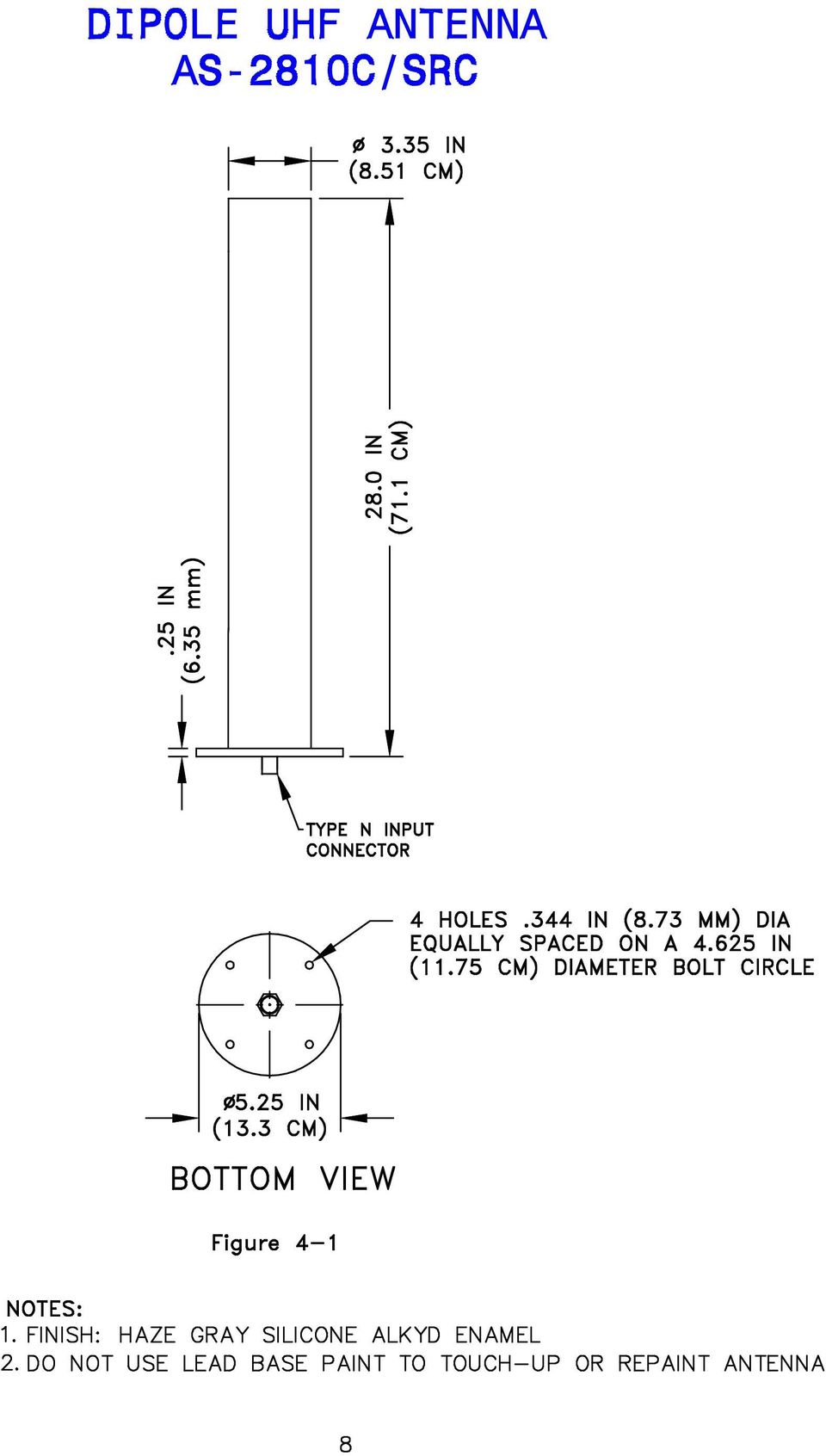
3 4-6 Installation Procedures Installation Checkout... 7 LIST OF ILLUSTRATIONS Figure Page 4-1 Dipole UHF Antenna AS-2810C / SRC... 8 LIST OF TABLES Table Page 1-1 Reference Data Equipment and Documents Supplied... 4 ii

4 SECTION 1 GENERAL INFORMATION AND SAFETY PRECAUTIONS 1-1. GENERAL SAFETY PRECAUTIONS. The following general safety precautions are not related to any specific procedures and therefore do not appear elsewhere in this publication. These are recommended precautions that personnel must understand and apply during many phases of operation and maintenance. WARNING Keep away from live circuits. Operating personnel must at all times observe all safety regulations, to prevent serious injury or death due to electrical shock. Do not service or adjust alone. Under no circumstances should any person service or adjust the equipment except in the presence of someone who is capable of rendering aid. Personnel working with or near high voltages should be familiar with modern methods of resuscitation. 1-2 SPECIFIC WARNINGS. The following specific precautions are related to inspecting and removing the antenna. WARNING Ensure that the transmitting equipment is de-energized prior to inspection of the antenna. Make sure the test equipment is properly grounded, to prevent electric shock. CAUTION Make sure the antenna is properly supported before removing its mounting hardware. CAUTION Do not coat the insulator with any substance; do not paint with lead base paints. 1

5 1-3. INTRODUCTION Purpose. This manual provides general information, operating and functional description, and installation data for the AS-2810C/SRC antenna. Information in this manual will assist in installing and operating the antenna Scope. This technical manual is provided to aid in the operation and installation of the antenna Applicability. This manual applies to the UHF Dipole Antenna AS-2810C/SRC EQUIPMENT DESCRIPTION General Description. The antenna, shown in Figure 4-1 is a 28 inch transmitting/receiving UHF dipole antenna for general use with UHF communications equipment. The antenna radiating elements are housed within a fibreglass insulator radome with an aluminum mounting base Capabilities. The antenna provides vertically polarized, omnidirectional azimuth radiation from 225 to 400 MHz. The aluminum antenna elements are high power dipole that can handle power up to 800 watts. The antenna meets high shock and vibration requirements Limitations. When used as directed, the antenna has no limitations RELATIONSHIP TO OTHER EQUIPMENT. The AS-2810C/SRC Antenna interfaces with UHF receiving and transmitting equipment with 50 ohm output REFERENCE DATA. Table 1-1 lists the reference data for the antenna EQUIPMENT ACCESSORIES, AND DOCUMENTS SUPPLIED. Table 1-2 lists the equipment and documents supplied. 2

6 Table 1-1. Reference Data PARAMETER NOMENCLATURE MANUFACTURER FREQUENCY RANGE VSWR GAIN IMPEDANCE INPUT INPUT CONNECTOR POLARIZATION POWER CAPABILITY RADIATION PATTERN OPERATING TEMPERATURE WIND VELOCITY HUMIDITY SHOCK VIBRATION HEIGHT WEIGHT BASE MOUNTING SPECIFICATION UHF DIPOLE ANTENNA AS-2810C/SRC VALCOM LIMITED TO 400 MHZ 2.0:1 MAXIMUM 1.5:1 AVERAGE 2 dbi 50 OHMS INPUT N-TYPE RECEPTACLE VERTICAL 500 W (AVERAGE) 800 W (PEAK) OMNIDIRECTIONAL -55 C TO +65 C (-60 F TO +150 F) 120 MPH (NO ICE) MIL-STD-810E, PROCEDURE III MEET MIL-S-901C, GRADE A QUALIFIED TO MEET MIL-STD TYPE I 28 ± 0.5 INCHES 5.5 POUNDS [2.47 KG] (MAX) ø 5.25 INCH ALUMINIUM FLANGE WITH 4 X ø INCH HOLES ON A ø INCH BOLT CIRCLE 3
 800 W (PEAK) OMNIDIRECTIONAL -55 C TO +65 C (-60 F TO +150 F) 120 MPH (NO ICE) MIL-STD-810E, PROCEDURE III")
7 Table 1-2. Equipment, Accessories and Documents Supplied QTY NOMENCLATURE OVERALL DIMENSIONS (INCHES) WEIGHT (POUNDS) CRATED UNCRATED UNCRATED HEIGHT DIA HEIGHT DIA 1 ANTENNA AS-2810C/SRC Base TECHNICAL MANUAL FOR AS-2810C/SRC ANTENNA 4

8 SECTION 2 OPERATION 2-1. INTRODUCTION. This chapter provides operating instructions for the antenna CONTROLS AND INDICATORS. The antenna contains no controls or indicators OPERATING PROCEDURES Operator Turn-On. No operator turn-on procedures apply since no power is required to operate the antenna. However, the antenna is coupled to RF equipment (transmitter/receiver) and to associated systems which may require energizing. For operating instructions, consult the appropriate technical manuals Modes of Operation. The antenna operates automatically, and no operator intervention is required other than interconnecting various associated equipment with the antenna Operation Under Interfering Conditions. No additional or alternate instructions are necessary to operate the antenna under interfering conditions Operator Turn-off. Since no power is required to operate the antenna, no operator turn-off is required. However, the specific equipment connected to the antenna may require operator turnoff. Consult the associated technical manuals for turn-off procedures Emergency Operation. No additional or alternate steps are necessary to operate the antenna under emergency conditions Emergency Turn-off. The antenna requires no emergency turn-off. For emergency turn-off of specific equipment connected to the antenna, consult the associated technical manuals. 5

9 SECTION 3 FUNCTIONAL DESCRIPTION 3-1. INTRODUCTION. This chapter provides the functional description of the antenna OVERALL LEVEL. The antenna is a base mounted, high-power antenna which provides omnidirectional coverage for general purpose communications reception and transmission from 225 to 400 MHz MAJOR FUNCTION LEVEL. The antenna consists of aluminum radiating elements that are housed within a fibreglass radome with an aluminum mounting base. The mounting base isolates the radiating elements of the antenna from the ground and physically supports the elements. The antenna does not require the external couplers. Only a transmitter or receiver is required to be connected to the antenna. 6

10 SECTION 4 INSTALLATION 4-1. SITE INFORMATION. Valcom's AS-2810C/SRC UHF Antenna is designed primarily for shipboard installation. The antenna can also be used at shore installations. The antenna should be installed in a non-obstructed environment, clear from any contiguous structures, such as masts, bulkheads, or other metal objects TOOLS AND MATERIALS REQUIRED. No special tools and materials are required for installation UNPACKING AND RE-PACKING. To unpack, carefully remove the screws holding the cover, and remove the antenna from the container. Save the container to pack the antenna for reshipment. No special handling procedures are required; observe normal precautions when handling the antenna FOUNDATION. The antenna should be installed vertically on a mounting plate that has bolt holes matching those in the antenna mounting base INPUT REQUIREMENTS. The Dipole UHF antenna has an rf power handling up to 800 watts at the 50 ohm input impedance INSTALLATION PROCEDURES. After unpacking the antenna, proceed with its installation as follows: a. Examine the exterior of the antenna for damage; make sure that the fibreglass radome and the mounting base have not been damaged, misaligned, or fractured. b. Secure the antenna to its mounting plate with four i0.312 inch hex head cap screws, flat washers, split lock-washers and nuts. c. Connect the system connector to the antenna at the input N-type receptacle INSTALLATION CHECKOUT. Checkout of the antenna after installation can only be accomplished by operating the receiving and transmitting equipment that is used with the antenna. Note: If replacing an existing antenna with a new antenna, it is recommended that new mounting hardware be used. 7

11
Cisco Aironet 2.4-GHz MIMO Wall-Mounted Omnidirectional Antenna (AIR-ANT2440NV-R)
") Cisco Aironet 2.4-GHz MIMO Wall-Mounted Omnidirectional Antenna (AIR-ANT2440NV-R) This document outlines the specifications for the Cisco Aironet 2.4-GHz MIMO Wall-Mounted Omnidirectional Antenna (AIR-ANT2440NV-R)
Cisco Aironet 2.4-GHz MIMO Wall-Mounted Omnidirectional Antenna (AIR-ANT2440NV-R) This document outlines the specifications for the Cisco Aironet 2.4-GHz MIMO Wall-Mounted Omnidirectional Antenna (AIR-ANT2440NV-R)
INSTALLATION INSTRUCTIONS HUSTLER 4-BTV, 5-BTV TRAP VERTICAL WARNING INSTALLATION OF THIS PRODUCT NEAR POWER LINES IS DANGEROUS
 INSTALLATION INSTRUCTIONS HUSTLER 4-BTV, 5-BTV TRAP VERTICAL WARNING INSTALLATION OF THIS PRODUCT NEAR POWER LINES IS DANGEROUS FOR YOUR SAFETY, FOLLOW THE INSTALLATION DIRECTIONS GENERAL DESCRIPTION:
Cisco Integrated 4G Low-profile Outdoor Saucer Antenna (ANT-4G-SR-OUT-TNC)
") CHAPTER 10 Cisco Integrated 4G Low-profile Outdoor Saucer Antenna (ANT-4G-SR-OUT-TNC) This document describes the Cisco Integrated 4G Low-profile Outdoor Saucer Antenna that is supported on the Cisco CGR
CHAPTER 10 Cisco Integrated 4G Low-profile Outdoor Saucer Antenna (ANT-4G-SR-OUT-TNC) This document describes the Cisco Integrated 4G Low-profile Outdoor Saucer Antenna that is supported on the Cisco CGR
NAVICOM DYNAMICS RTK BASE STATION INSTALLATION AND COMMISSIONING INSTRUCTIONS
 NAVICOM DYNAMICS RTK BASE STATION INSTALLATION AND COMMISSIONING INSTRUCTIONS 1. Locate a suitable position inside the building to install the Base Station enclosure where mains power (240V AC) is available
Cellular Wireless Antennas
 Cellular Wireless Antennas A Technical Brief GarrettCom Inc., November 2010 Overview The Cellular Wireless Antenna Technical brief is provided to assist with the design and deployment of the DX940 Cellular
All specifications are subject to change without notice. The latest specifications are available at www.kathrein-scala.com.
 ISO 9001 Quality and ISO 14001 Environmental Management Kathrein-Scala is an ISO 9001 and ISO 14001 certified company and is in voluntary compliance with EU Directive 02-95-EC for Reduction of Hazardous
SMA Connectors. RF Coax Connectors. Product Facts
 SMA Connectors Product Facts Performance to 12.4 GHz and beyond Available in various base metal options, including stainless steel, brass and zinc diecast Uses industry standard crimp tools and processes
Antenna Trainer EAN. www.edibon.com. Technical Teaching Equipment INTRODUCTION
 Antenna Trainer EAN Technical Teaching Equipment Products Products range Units 3.-Communications INTRODUCTION Antennas are the main element of aerial communications. They are the transition between a transmission
SMA Waterproof. Cable Assembly. Filtered Audio Connector. Dataport Receptacle. Dataport Plug
 INTERCONNECT SOLUTIONS FOR RUGGEDIZED COMMUNICATIONS GPS Antenna Gooseneck Adapter TNC Waterproof Cable Assembly Communication radios often carry critical public safety information and must operate reliably
This document is available at HTTP://WWW.FALCOM.DE/. FAL-ANT-1. GSM/DCS/GPS antenna (with Fakra-SMB connectors) Description. Version 1.
 Description. Version 1.") This document is available at HTTP://WWW.FALCOM.DE/. FAL-ANT-1 GSM/DCS/GPS antenna (with Fakra-SMB connectors) Description Version 1.00 Contents 0 INTRODUCTION...3 0.1 GENERAL... 3 1 SECURITY...4 1.1 GENERAL...
This document is available at HTTP://WWW.FALCOM.DE/. FAL-ANT-1 GSM/DCS/GPS antenna (with Fakra-SMB connectors) Description Version 1.00 Contents 0 INTRODUCTION...3 0.1 GENERAL... 3 1 SECURITY...4 1.1 GENERAL...
ANOISON HPQN SERIES HPQN CONNECTORS INTERFACE DIMENSIONS. Description. Interface Dimensions 21 Characteristics
 SERIES HPQN CONNECTORS DESCRIPTION CONTENT Designed by James Qu at Anoison in 2006, the HPQN is a quick locking version of the widely used type N connector. By replacing the threaded interface of the original
ANTENNER och TILLBEHÖR
 ANTENNER och TILLBEHÖR Antenner Fästen Monteringstillbehör Kablar Kontakter SPARK / DB / 6 ANTENNA TYPE VHF fiberglass antenna incl. 5 mtr RG-58 and 1 pc PL-259 connector FREQUENCY 156-162 MHz IMPEDANCE
M2 Antenna Systems, Inc. Model No: KT34M2
 M2 Antenna Systems, Inc. Model No: KT34M2 10m f, MHz G, dbi F/B, db 28.0 7.3 18 28.2 7.3 23 28.4 7.4 25 28.6 7.5 24 29.2 7.6 20 15m f, MHz G, dbi F/B, db 21.0 6.9 19 21.1 6.9 22 21.2 7.0 24 21.3 7.0 24
470-806 MHz. Band IV/V (UHF) TV Slot Antennas. www.rfsworld.com. RD Series BROADCAST & HF ANTENNAS
 TV Slot Antennas. www.rfsworld.com. RD Series BROADCAST & HF ANTENNAS") RD Series The RD Series of broadband UHF antennas are lightweight in design, yet rugged in approach. They solve the critical question of using a single UHF antenna for multichannel Analog and DTV Broadcasting.
RD Series The RD Series of broadband UHF antennas are lightweight in design, yet rugged in approach. They solve the critical question of using a single UHF antenna for multichannel Analog and DTV Broadcasting.
SMA Interface Mating Dimensions (Per MIL-STD-348)
") SMA Series SMA 6 SMA Interface Mating Dimensions (Per MIL-STD-348) SMA Interface Dimensions MALE Inches/Millimeters 3 Minimum Nominal Maximum LTR in. mm in. mm in. mm A.250 6.35.263 6.68.. B.1790 4.55.1808
SMA Series SMA 6 SMA Interface Mating Dimensions (Per MIL-STD-348) SMA Interface Dimensions MALE Inches/Millimeters 3 Minimum Nominal Maximum LTR in. mm in. mm in. mm A.250 6.35.263 6.68.. B.1790 4.55.1808
ProCurve External Access Point Antennas
 Certified for use with ProCurve Wireless Access Point 420, the ProCurve family of access point antennas is specifically designed to meet the needs of today's most demanding wireless LAN deployments. ProCurve
Digital Active Indoor Antenna SRT ANT 10 ECO
 Digital Active Indoor Antenna SRT ANT 10 ECO Picture similar User Manual Table of contents 1.0 INTRODUCTION 1 2.0 PACKAGE CONTENT 1 3.0 SAFETY NOTES 2 4.0 CONNECTING THE ANTENNA 2 1.0 INTRODUCTION Thank
1000-LB. TRAILER JACK OWNER S MANUAL
 1000-LB. TRAILER JACK OWNER S MANUAL WARNING: Read carefully and understand all INSTRUCTIONS before operating. Failure to follow the safety rules and other basic safety precautions may result in serious
SSC-T800series. New type with radial cross ray method. Light Curtain Sensors. Type. Radial Cross Ray Method. Detecting width. Light axis interval
 series Light Curtain Sensors New type with radial cross ray method Small objects and flat tape-like objects detected Convenient simplified wiring requiring no clock (synchronization) line Compact and flat
HDTV. Amplified Indoor Outdoor Antenna. indoor outdoor. 10 db Amplification. Paintable. Versatile TERRESTRIAL VHF UHF
 Amplified Indoor Outdoor Antenna VHF UHF 10 db Amplification fixed 10 db amplification for improved reception of weak signals Paintable customize your antenna color to match your interior or exterior décor
Installation Instructions Hustler 6-BTV Trap Vertical
 Installation Instructions Hustler 6-BTV Trap Vertical ASSEMBLY 1. Check the package contents against the parts list on page 2. 2. WARNING. Installation of this product near power lines is dangerous. For
27 512 MHz KATHREIN-Antennas and Antenna Line Products. For Public Safety, Ports, Airports, Distribution, Public Transport, Utilities
 27 512 MHz KATHREIN-Antennas and Antenna Line Products For Public Safety, Ports, Airports, Distribution, Public Transport, Utilities Photo on title page: Applications for TETRA. Catalogue Issue 1/211 All
PPS-PPQ-BT-PIAS RESIN INSULATORS FOR OIL INSULATED ELECTRICAL MACHINES
 PPS-PPQ-BT-PIAS RESIN INSULATORS FOR OIL INSULATED ELECTRICAL MACHINES BUSHING WITH PLUG CONNECTION WITH OUTER CONE PPS CHARACTERISTICS The PPS bushing can be used as a fixed section for the entry of medium
LOW GAIN BASE STATION ANTENNA AV1312-1A
 SPECIALS : AV1312-1A LOW GAIN BASE STATION ANTENNA AV1312-1A AV1312-1A 118 144 MHz 26 MHz 50 Ω DC grounded 1,5 max/depending on mounting 2 dbi E-plane 3 db beamwidth 70 H-plane 3 db beamwidth 200 /depending
INSTALLATION AND OPERATING INSTRUCTIONS For Model GL1 Gate Locks
 Securitron Magnalock Corp. www.securitron.com ASSA ABLOY, the global leader Tel 800.624.5625 techsupport@securitron.com in door opening solutions INSTALLATION AND OPERATING INSTRUCTIONS For Model GL1 Gate
This Antenna Basics reference guide includes basic information about antenna types, how antennas work, gain, and some installation examples.
 Antenna Basics This Antenna Basics reference guide includes basic information about antenna types, how antennas work, gain, and some installation examples. What Do Antennas Do? Antennas transmit radio
EH-20 20m antenna. By VE3RGW
 EH-20 20m antenna By VE3RGW Equivalent circuit of EH-20 (prototype 2A) antenna system. Upper cylinder Lower cylinder Ground Counter pose Phasing coil Impedance transformer and tune circuit Tune coil Feed
Operating Instructions
 Operating Instructions Series L 000 Cord Reels Model Numbers: L 000 L 0 0 L 0 B L 0 X L 00 L A X L 0 L 0 0 L 00 L 0 L 0 B L 0 0 X L 00 L 0 A L 0 X IMPORTANT Read this manual carefully before installing,
Avaya WLAN 9100 External Antennas for use with the WAO-9122 Access Point
 Avaya WLAN 9100 External Antennas for use with the WAO-9122 Access Point Overview To optimize the overall performance of a WLAN in an outdoor deployment it is important to understand how to maximize coverage
Antenna Deployment Technical Brief
 ProCurve Networking Antenna Deployment Technical Brief Introduction... 2 Antenna types... 2 Omni directional antennas... 2 Directional antennas... 2 Diversity antennas... 3 High gain directional antennas...
Cross-beam scanning system to detect slim objects. 100 mm 3.937 in
 891 Object Area Sensor General terms and conditions... F-17 Related Information Glossary of terms... P.1359~ Sensor selection guide...p.831~ General precautions... P.1405 PHOTO PHOTO Conforming to EMC
In-Ground Basketball System Owners Manual
 In-Ground Basketball System Owners Manual Customer Service Center N53 W4700 South Corporate Circle Sussex, WI 53089 U.S.A. Write Model Number From Box Here: WARNING! 3 Capable Adults REQUIRED TOOLS AND
Digital TV Coat Hanger Antenna
 Rabbit ears are for rabbits, not digital televisions. In this project, we ll show you how to build your own digital TV antenna from wire hangers, a piece of wood and some pipe. Television antennas are
Digital TV Coat Hanger Antenna
 Rabbit ears are for rabbits, not digital televisions. In this project, we ll show you how to build your own digital TV antenna from wire hangers, a piece of wood and some pipe. Television antennas are
F-Series Camera Mounting Accessories
 F-Series Camera Mounting Accessories Document Number: 427-0462-00-12 Version: 100 Issue Date: September 2010 2010. All rights reserved worldwide. FLIR Commercial Systems, Inc. 70 Castilian Drive Goleta,
Deluxe Welding Tool Chest
 Item# 164782 OPERATOR S MANUAL Read carefully and understand RULES FOR SAFE OPERATION and instructions before operating. Failure to follow the safety rules and other basic safety precautions may result
Selecting Receiving Antennas for Radio Tracking
 Selecting Receiving Antennas for Radio Tracking Larry B Kuechle, Advanced Telemetry Systems, Inc. Isanti, Minnesota 55040 lkuechle@atstrack.com The receiving antenna is an integral part of any radio location
Antenna Splitter ASA 1. Instruction manual
 Antenna Splitter ASA 1 Instruction manual Contents Important safety instructions... 2 The ASA 1 active antenna splitter... 4 Delivery includes... 4 Operating elements... 5 Putting the ASA 1 into operation...
REDI-LINE ELECTRIC GENERATORS USER'S GUIDE. Rugged, Reliable, DC to AC Power Conversion
 REDI-LINE ELECTRIC GENERATORS USER'S GUIDE Rugged, Reliable, DC to AC Power Conversion REDI-LINE ELECTRIC GENERATOR MODEL INPUT ACTUAL OUTPUT ACTUAL OUTPUT WATTS SERIAL NO. PACIFIC SCIENTIFIC MOTOR PRODUCTS
Step 1. Item 6. Item 1
 Voltage Regulators QD3/T350 Motor Replacement Kit Kit Number 57A63675100B Service Information S225-50-35 Contents General..................................... 1 Parts Supplied...............................
Byonics Micro Trak 1000 High Altitude Balloon Tracker
 Byonics Micro Trak 1000 High Altitude Balloon Tracker The Micro Trak 1000 (MT 1000) is a high altitude balloon (HAB) tracker. It is usually sold as a combination to provide a simple, turn key tracking
CELO5. User & Installation Manual. www.audac.eu
 CELO5 User & Installation Manual www.audac.eu 2 Introduction 5 High-end Slim Ceiling Speaker The CELO5 is the 5 version of AUDAC s CELO High-end Slim ceiling speaker series with an RMS power of 50 Watt
Givare NC-SRS 280 och 880
 Givare NC-SRS 280 och 880 Aratron AB/Nordic Control, 02 03 SRS280SEALED ROTARY SENSOR PERFORMANCE ±2 Resistance ±20% Hysteresis (repeatability) Accuracy Applied voltage maximum Resolution Output smoothness
Operating Instructions
 Operating Instructions Series L 4000 Spring Driven Cord Reels 63 3 3 3 7A 63 0 63 3 3-RP 3 7B 63 X 6 3 3A 63 8 3 X 6 3 3A-RP 63 8 L 4000 63 3 3 3B 63 9 L 400 63 3-RP A 63 5 3 9 L 4500 63 3 A 63 5 3 9G
Guide. Installation. Signal Booster. Wilson. In-Building Wireless Smart Technology Signal Booster. Contents:
 Signal Booster Installation Guide In-Building Wireless Smart Technology Signal Booster Contents: Antenna Options and Accessories................... 1 Before Getting Started / How It Works...............
758 Heavy-duty Ratchet Guy Wire Cutter
 INSTRUCTION MANUAL 758 Heavy-duty Ratchet Guy Wire Cutter Read and understand all of the instructions and safety information in this manual before operating or servicing this tool. Register this product
EVOLUTION Thermal Imaging Camera Remote Wireless Video Receiver System
 EVOLUTION Thermal Imaging Camera Remote Wireless Video Receiver System Instruction Manual DELUXE AND MINI RECEIVER KIT (RX) INSTRUCTIONS " WARNING THIS MANUAL MUST BE READ CAREFULLY BY ALL INDIVIDUALS
ANTENNA DISTRIBUTION SYSTEM USER'S GUIDE
 Model User Guide ANTENNA DISTRIBUTION SYSTEM USER'S GUIDE 2009 Shure Incorporated 27AS8862 (Rev.4) Printed in U.S.A. POWERING ON/POWERING OFF THE Last powered on First powered off To avoid damaging internal
Guide To Returning Your Satellite Modem and Radio Assembly Model: HN7000S
 Guide To Returning Your Satellite Modem and Radio Assembly Model: HN7000S The HughesNet modem with power supply and radio must be returned to Hughes, in good condition, within 45 days of your termination.
Express5800/120Ed. Rack Mount Kit Installation Procedures PN: 455-01607-001
 Express5800/120Ed Rack Mount Kit Installation Procedures PN: 455-01607-001 Proprietary Notice and Liability Disclaimer The information disclosed in this document, including all designs and related materials,
Mitel DECT Base Stations
 Mitel DECT Base Stations On-site Mobility for Professionals The Mitel BS300 range of base stations offers a variety of coverage patterns to suit different situations. By choosing the right mix of base
Achat 208 HL / 208 HR passive mid-range speaker. user manual
 Achat 208 HL / 208 HR passive mid-range speaker user manual Musikhaus Thomann Thomann GmbH Hans-Thomann-Straße 1 96138 Burgebrach Germany Telephone: +49 (0) 9546 9223-0 E-mail: info@thomann.de Internet:
800 10766 700 MHz Dual Band 8', 65 Degree Antenna RET
 8 766 7 MHz Dual Band 8', 65 Degree Antenna RET X-polarized (+45 and -45 ). UV resistant fiberglass radomes. Wideband vector dipole technology. DC Grounded metallic parts for impulse suppression. RET motor
Toroidal Conductivity Sensor
 Instruction Sheet PN 51A-/rev.C June 2012 Toroidal Conductivity Sensor For additional information, please visit our website at www.emersonprocess.com/rosemountanalytical.com SPECIFICATIONS Wetted Materials:
ANTENNA SYSTEMS. 1.8m Offset TxRx Antenna INSTALLATION & ASSEMBLY INSTRUCTIONS
 ANTENNA SYSTEMS 1.8m Offset TxRx Antenna INSTALLATION & ASSEMBLY INSTRUCTIONS LIMITED TWELVE (12) MONTH WARRANTY This PATRIOT ANTENNA equipment is warranted to be free from defects in material and workmanship
DISCRETE SEMICONDUCTORS DATA SHEET. BLF244 VHF power MOS transistor
 DISCRETE SEMICONDUCTORS DATA SHEET September 1992 FEATURES High power gain Low noise figure Easy power control Good thermal stability Withstands full load mismatch Gold metallization ensures excellent
Antenna Part Number: FR05-S1-R-0-105
 Fractus EZConnect Zigbee, RFID, ISM868/9 Chip Antenna Antenna Part Number: FR5-S1-R--15 This product is protected by at least the following patents PAT. US 7,148,85, US 7,22,822 and other domestic and
Embedded FM/TV Antenna System
 1 Embedded FM/TV Antenna System Final Report Prepared for By January 21, 2011 2 Table of Contents 1 Introduction... 5 2 Technical Specification... 6 3 Prototype Antenna... 7 4 FASTROAD Active module fabrication...
Required Supplies for Installing Check Tag Assembly
 Check Tag Assembly and Antenna Installation Instructions 411922-004 05/10 This document explains how to install and connect the check tag assembly and check tag antenna. Required Supplies for Installing
ANT1750F Multi-Directional Slim Digital Antenna / Antena multidireccional plana para interiores / Antenne numérique mince multidirectionnelle
 Multi-Directional Slim Digital Antenna / Antena multidireccional plana para interiores / Antenne numérique mince multidirectionnelle User s Guide / Guía del Usuario / Guide de l utilisateur FCC Statement
5. ANTENNA TYPES. Figure 5. The vertical dipole and its electromagnetic equivalent, the vertical monopole
 Antennas can be classified in several ways. One way is the frequency band of operation. Others include physical structure and electrical/electromagnetic design. The antennas commonly used for LMR both
RAY-MAX Integrated Solar Power Strip
 RAY-MAX Integrated Solar Power Strip 600008, 600009, 600010, 600208, 600209, 600210 Owner s Manual NEXTRONEX, INC. Revision Date: 10/27/14 Contents 1. Safety Instructions... 3 2. General Equipment Warnings...
Installation. Smart-UPS VT MGE Galaxy 3500. Maintenance Bypass Panel. 10-40 kva 400 V
 Installation Smart-UPS VT MGE Galaxy 3500 Maintenance Bypass Panel 10-40 kva 400 V Contents Safety.................................................. 1 Save these instructions...................................
4.3-inch Back-Up Camera
 TM 4.-inch Back-Up Camera Model No.: PKC0BU4 Owner s Manual and Warranty Information Read these instructions completely before using this product. Retain this Owner s Manual for future reference. INTRODUCTION
EVOLUTION Thermal Imaging Camera Remote Wireless Video Receiver System
 EVOLUTION Thermal Imaging Camera Remote Wireless Video Receiver System Instruction Manual DELUXE AND MINI RECEIVER KIT (RX) INSTRUCTIONS " WARNING THIS MANUAL MUST BE READ CAREFULLY BY ALL INDIVIDUALS
SPECIAL NOTICE. All references to NAT product part numbers (and associated images) are equivalent to AEM product part numbers.
 are equivalent to AEM product part numbers.") SPECIAL NOTICE This product is now licensed to Anodyne Electronics Manufacturing (AEM) from Northern Airborne Technology (NAT). AEM is responsible for all matters related to this product, including sales,
SPECIAL NOTICE This product is now licensed to Anodyne Electronics Manufacturing (AEM) from Northern Airborne Technology (NAT). AEM is responsible for all matters related to this product, including sales,
PowerFlex 700S and 700H Frame 12 DC Bus Connector Kit
 PowerFlex 700S and 700H Frame 12 DC Bus Connector Kit Installation Instructions This document provides instructions for the installation of a DC bus connector kit for PowerFlex 700S and 700H frame 12 drives
JP Tribander Owner Manual
 JP Tribander Owner Manual JP-Tribander Technical overview JP-Tribander is effective tribander beam for 20m, 15m and 10meters with full size elements without traps. Antenna is designed using latest computer
Broadband Telecommunications Drop Amplifier
 INSTALL SHEET BDA Broadband Telecommunications Drop Amplifier Introduction The Broadband Telecommunications Drop Amplifier (BDA) is a two-way, 1 GHz amplifier designed for customer-premise amplification
VOLTAGE/CURRENT CALIBRATOR ISO-TECH ILC-421
 VOLTAGE/CURRENT CALIBRATOR ISO-TECH ILC-421 TABLE OF CONTENTS 1. FEATURES... 1 2. SPECIFICATIONS... 1 2-1 General Specifications...1 2-2 Electrical Specifications... 2 3. FRONT PANEL DESCRIPTION... 4 3-1
Antenna Basic Concepts
 ANTENNA An antenna is a device to transmit and/or receive electromagnetic waves. Electromagnetic waves are often referred to as radio waves. Most antennas are resonant devices, which operate efficiently
Operation Manual for Users
 Operation Manual for Users Model No.: FLTAMFMRCD!!!!!!!!!! ATTENTION!!!!!!!!!! THE RESET BUTTON MUST BE PRESSED TO ENSURE PROPER OPERATION. SEE INSTRUCTION MANUAL Table of Contents Table of Contents ---------------------------------------------------------------------------------------------
MTE SERIES RLW. World REACTORS USER MANUAL PART NO. INSTR 030 REL. 090930. 2009 MTE Corporation
 MTE SERIES RLW World REACTORS USER MANUAL PART NO. INSTR 030 REL. 090930 2009 MTE Corporation IMPORTANT USER INFORMATION NOTICE MTE Series RLW reactors are components designed to improve the reliability
8" BENCH GRINDER OWNER'S MANUAL
 8" BENCH GRINDER OWNER'S MANUAL WARNING: Read carefully and understand all INSTRUCTIONS before operating. Failure to follow the safety rules and other basic safety precautions may result in serious personal
LOW GAIN FM ANTENNA AV1311-95
 FM/TV : AV1311-95 LOW GAIN FM ANTENNA AV1311-95 AV1311-95 88 108 MHz 1,5 max Vertical 2 dbi E-plane 3 db beamwidth 70 H-plane 3 db beamwidth 200 /depending on mounting 6 db/depending on mounting 0,5 kw
Series P215PR/RM Direct- and Remote-Mount Pressure-Actuated Condenser Fan Speed Controllers for Single-Phase Motors
 European Refrigeration Controls Catalogue Catalogue Section 4 Product Bulletin P215PR/RM Issue 01/03/2013 Series P215PR/RM Direct- and Remote-Mount Pressure-Actuated Condenser Fan Speed Controllers for
Antenna Guide. Wireless LAN Antennas of the BAT family. BAT Antenna Guide BAT Release 09 05/2015
 Antenna Guide Wireless LAN Antennas of the BAT family Release 9 5/215 Technical Support https://hirschmann-support.belden.eu.com The naming of copyrighted trademarks in this manual, even when not specially
ATS Overhead Table Shelf System INSTRUCTION MANUAL
 ATS Overhead Table Shelf System INSTRUCTION MANUAL ATS Overhead Table Shelf System Instruction Manual Warranty Newport Corporation warrants this product to be free of defects in material and workmanship
Agilent X/P/K281C Adapters
 Agilent X/P/K281C Adapters Including Options 006, 012, 013, 106 Operating and Service Manual Contents 1 Introduction 7 Product Overview 8 Options 8 Instruments Covered by Manual 10 2 Installation 11 Initial
Installation and User s Manual Global Tracking and Tracing System. GTTS-2000Bi
 Installation and User s Manual Global Tracking and Tracing System GTTS-2000Bi Version 1.4 - January 2016 T +31570 606088 E info@gtts.eu W www.gtts.eu Page 1 of 11 1. Preface The information in this Installation
These Installation Instructions are valid for antennas in the following version:
 Installation Instructions 4 ft CompactLine Antennas (with E-Mount 250 km/h) SB, SBX NMT 560-05(e) These Installation Instructions are valid for antennas in the following version: Reflector Ø 1.2 m (4 ft)
DP-DMX20L 4 CHANNEL DMX DIMMER PACK MODE MENU DISPLAY. OUTPUT: 10A/CH, TOTAL 20A Max. DMX CHANNEL RECEIVE TOTAL DMX CHANNEL DIMMER / SWITCH
 DP-DMX0L OUTPUT: 0A/CH, TOTAL 0A Max. CHANNEL DMX DIMMER PACK DISPLAY RECEIVE DMX CHANNEL TOTAL DMX CHANNEL DIMMER / SWITCH 8888 CHASE PROGRAM CHASE CHASE SPEED CHASE DIMMER MODE MENU Elation Professional
SERIES ASM NEOPRENE/EPMD FLANGED SINGLE SPHERE CONNECTOR CONNECTORS. Pressures to 225 PSIG (15.51 barg) Temperatures to 230ºF (110ºC)
 Temperatures to 230ºF (110ºC)") APPLICATIONS Process Industry Weak Acids Alkalies Compressed Air Pulp & Paper MODELS ASM - Flanged Connection OPTIONS Control Rods Oil & Gas Water & Waste Pump suction & discharge Sea water Chemical lines
APPLICATIONS Process Industry Weak Acids Alkalies Compressed Air Pulp & Paper MODELS ASM - Flanged Connection OPTIONS Control Rods Oil & Gas Water & Waste Pump suction & discharge Sea water Chemical lines
=============================== WARNING
 =============================== WARNING EXPLANATION OF GRAPHICAL SYMBOLS This symbol is intended to alert the user to the presence of unprotected dangerous voltage" within the product's enclosure that
NPN Darlington Power Silicon Transistor Qualified per MIL-PRF-19500/472
 and Available on commercial versions NPN Darlington Power Silicon Transistor Qualified per MIL-PRF-19500/472 DESCRIPTION Qualified Levels: JAN, JANTX, and JANTX This high speed NPN transistor is military
OPERATING and MAINTENANCE MANUAL SERIES 2700A CONTROL VALVE CONTENTS. INTRODUCTION...1 Scope...1 Description...1 Valve Identification...
 OPERATING and MAINTENANCE MANUAL SERIES 2700A CONTROL VALVE CONTENTS INTRODUCTION...1 Scope...1 Description...1 Valve Identification...2 1.0 VALVE INSTALLATION...2 2.0 VALVE MAINTENANCE...3 Actuator Disassembly...3
Flexible PCB Antenna with Cable Integration Application Note Version 2
 Flexible PCB Antenna with Cable Integration Application Note Version 2 CONTENTS 1. BASICS 2. APPLICATIONS 3. SIZE 4. SHAPE 5. GROUND PLANE SIZE 6. IMPEDANCE 7. BANDWIDTH 8. VSWR 9. GAIN 10. EFFICIENCY
Antenna Properties and their impact on Wireless System Performance. Dr. Steven R. Best. Cushcraft Corporation 48 Perimeter Road Manchester, NH 03013
 Antenna Properties and their impact on Wireless System Performance Dr. Steven R. Best Cushcraft Corporation 48 Perimeter Road Manchester, NH 03013 Phone (603) 627-7877 FAX: (603) 627-1764 Email: sbest@cushcraft.com
Times Microwave Systems Hermetically Sealed Assemblies
 SCOPE This Specification details the Electrical, Mechanical and Environmental Characteristics of Times Microwave Systems MILTECH 340.34 Diameter Hermetically Sealed Coaxial Transmission Lines. This product
OWNER S MANUAL Table Tennis Table Patent Pending
 OWNER S MANUAL Table Tennis Table Patent Pending Be sure to write your model number and serial number here for future reference. You can find these numbers printed on the bottom of the table. MODEL # T8179
Electrical TV Lift mechanism TS750. Parts included with your TV Lift
 Parts included with your TV Lift Lift unit ( #1 ) Power supply ( #2 ) R.F. Module ( #3 ) Rocker switch ( #4 ) Remote Control (not shown) Plasma screen brackets ( #6a ) Lift Brackets ( #6b ) Lid Lifter
Contents. 2 NP560-NP562 Installation Guide YML821 Rev1
 Contents Introduction...4 Package Contents...5 Installing the NetComm Indoor Wireless Booster (NP560/NP562)...6 Electrical Specification...8 Appendix A: Registration and Warranty Information...9 2 NP560-NP562
SMD Rework Station TABLE OF CONTENTS
 SMD Rework Station Thank you for purchasing the Hakko 50B SMD Rework Station. The Hakko 50B is designed to solder and desolder surface mounted devices with hot air. Please read this manual before operating
'' EGGBEATER '' ANTENNA VHF/UHF ~ PART 2
 '' EGGBEATER '' ANTENNA VHF/UHF ~ PART 2 ON6WG / F5VIF Summary Note : In Part 1, Fig 1 shows a maximum gain of 6.45 dbi. Several design attempts were made using slightly different configurations ( i.e.
Installation Instructions For Slider Casement Air Conditioners
 Installation Instructions For Slider Casement Air Conditioners NOTE: These instructions describe installation in a typical wood framed window with a wood SLIDE-BY sash, or installation in a metal CASEMENT
High Frequency Ceramic Solutions
 Page 1 of 6 General Specifications - Mounting Part Number 2450AT43A100 Frequency Range 2400-2500 Mhz Peak Gain 2.0 dbi typ. (-V) Average Gain 0.5 dbi typ. (-V) 9.5 db min. Input Power Impedance Operating
Jack to Jack adapters Plug to Plug U-Link connectors PCB Right angle plastic PCB Right angle - metal. Ordering Codes
 BNC 75Ω RF CONNECTORS BNC 75Ω RF CONNECTORS To meet the need for higher performance, impedance matched cable interconnections, Amphenol offers a full line of 75 ohm BNC connectors. These connectors can
Wideband Active Loop Antenna Amplifier with Passive Augmentation
 Wideband Active Loop Antenna Amplifier with Passive Augmentation Transformer T1 is the inline transmission line current transformer, described on the next page. Transformers T2 and T3 are the augmentation
ARCO Electric Products Installation and Maintenance Manual Low Voltage Automatic Power Factor Correction Capacitor Systems 2013
 ARCO Electric Products Installation and Maintenance Manual Low Voltage Automatic Power Factor Correction Capacitor Systems 2013 READ CAREFULLY These instructions are intended to cover good practices in